EP1559170B1 - Abgeschirmte antenne für leser oder sender/empfänger - Google Patents
Abgeschirmte antenne für leser oder sender/empfänger Download PDFInfo
- Publication number
- EP1559170B1 EP1559170B1 EP02787538.4A EP02787538A EP1559170B1 EP 1559170 B1 EP1559170 B1 EP 1559170B1 EP 02787538 A EP02787538 A EP 02787538A EP 1559170 B1 EP1559170 B1 EP 1559170B1
- Authority
- EP
- European Patent Office
- Prior art keywords
- coils
- group
- turns
- antenna
- coil
- Prior art date
- Legal status (The legal status is an assumption and is not a legal conclusion. Google has not performed a legal analysis and makes no representation as to the accuracy of the status listed.)
- Expired - Lifetime
Links
- 230000010363 phase shift Effects 0.000 claims description 16
- 230000007423 decrease Effects 0.000 claims description 6
- 230000003247 decreasing effect Effects 0.000 claims description 3
- 238000010586 diagram Methods 0.000 description 2
Images



Classifications
-
- H—ELECTRICITY
- H01—ELECTRIC ELEMENTS
- H01Q—ANTENNAS, i.e. RADIO AERIALS
- H01Q1/00—Details of, or arrangements associated with, antennas
- H01Q1/12—Supports; Mounting means
- H01Q1/22—Supports; Mounting means by structural association with other equipment or articles
-
- H—ELECTRICITY
- H01—ELECTRIC ELEMENTS
- H01Q—ANTENNAS, i.e. RADIO AERIALS
- H01Q1/00—Details of, or arrangements associated with, antennas
- H01Q1/12—Supports; Mounting means
- H01Q1/22—Supports; Mounting means by structural association with other equipment or articles
- H01Q1/2208—Supports; Mounting means by structural association with other equipment or articles associated with components used in interrogation type services, i.e. in systems for information exchange between an interrogator/reader and a tag/transponder, e.g. in Radio Frequency Identification [RFID] systems
-
- H—ELECTRICITY
- H01—ELECTRIC ELEMENTS
- H01Q—ANTENNAS, i.e. RADIO AERIALS
- H01Q1/00—Details of, or arrangements associated with, antennas
- H01Q1/12—Supports; Mounting means
- H01Q1/22—Supports; Mounting means by structural association with other equipment or articles
- H01Q1/2208—Supports; Mounting means by structural association with other equipment or articles associated with components used in interrogation type services, i.e. in systems for information exchange between an interrogator/reader and a tag/transponder, e.g. in Radio Frequency Identification [RFID] systems
- H01Q1/2216—Supports; Mounting means by structural association with other equipment or articles associated with components used in interrogation type services, i.e. in systems for information exchange between an interrogator/reader and a tag/transponder, e.g. in Radio Frequency Identification [RFID] systems used in interrogator/reader equipment
-
- H—ELECTRICITY
- H01—ELECTRIC ELEMENTS
- H01Q—ANTENNAS, i.e. RADIO AERIALS
- H01Q7/00—Loop antennas with a substantially uniform current distribution around the loop and having a directional radiation pattern in a plane perpendicular to the plane of the loop
- H01Q7/04—Screened antennas
Definitions
- the present invention relates to a reader or transmitter equipped with a shielded antenna.
- the invention relates to such a device provided for communicating with transponders placed inside a communication volume defined by the antenna, in particular by the geometric dimensions thereof.
- the communication volume is provided inside a rectangular cylinder or parallelepiped around which the antenna is arranged.
- a central coil 2 defining inside its turns 4 a communication volume 6 and, on either side of this coil 2, two shielding coils 8 and 9.
- the coils 8 and 9 are arranged at a certain distance from the coil 2.
- the coils 8 and 9 are supplied with a phase shift of 180 ° relative to the central communication coil.
- a sharp decrease in the amplitude of the field of the shielded antenna occurs between the three regions dominated by the respective fields of the three coils considered.
- regions 11 and 12 for decreasing the amplitude of the magnetic field thus result from the aforementioned 180 ° phase shift for feeding the shielding coils.
- the decrease in the magnetic field is relatively large, so that communication between the reader or transmitter transponders can be assured in these regions. Therefore, the active area ZA of the shielded antenna shown in FIG. figure 1 is limited within the geometrical dimensions of the coil 2. This represents a major disadvantage for such a device.
- the shielded antenna of the prior art according to the figure 1 has a useful communication volume of a relatively small length ZA with respect to the total length L of the shielded antenna.
- An object of the present invention is to overcome the major disadvantage mentioned above by providing a reader or transmitter with a shielded antenna whose useful area of communication substantially corresponds to the total length of the shielded antenna.
- the document WO9638877 A1 discloses an article surveillance system comprising a plurality of coils.
- the invention relates to a reader or transmitter intended to communicate with transponders whose antenna is formed of several turns defining a central axis and a global interior volume, characterized in that this antenna comprises a first group of turns forming at least two first coils and a second group of turns forming two second coils, these first and second coils being supplied in phase quadrature and arranged to generate a communication field with an approximately constant amplitude on substantially the entire length of said antenna along its central axis and decreasing rapidly outside this antenna away from it.
- the shielded antenna of the prior art shown in FIG. figure 1 by incorporating two compensation coils between the central coil and respectively the two end coils, these two compensation coils being supplied with a phase shift of 90 ° relative to the other three coils.
- These two compensation coils are supplied with a phase shift of 180 ° between them, so as to quickly cancel their resulting field out of the antenna, and are arranged relative to the first three coils shown in FIG. figure 1 in order to compensate for the decrease of the magnetic field in the regions 11 and 12, ie between the central coil 2 and the end coils 8 and 9.
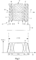
- FIG. 1 a first embodiment of the invention.
- the coils 8 and 9 are fed by the power supply and control means 20 of the reader 22 with a phase shift of 180 ° relative to the central coil 6.
- the coils 16 and 17 are fed one relative to the other with a phase shift also of 180 ° and with a phase shift of 90 ° relative to the other coils 6, 8 and 9.
- the two coils 16 and 17 are arranged so that their magnetic field along the central axis 24 of the antenna 14 is maximum respectively in the two regions 11 and 12 where the resulting magnetic field for the three coils 6, 8 and 9 decreases or vanishes, as shown in the graph of FIG. figure 2 which shows these amplitudes of the magnetic field H along the central axis 24 of the antenna.
- Power phase shifts are described by a cosine (Sin) and sin (Sin) supply with one of the two +/- arithmetic signs placed in front.
- each coil along the central axis 24 and the characteristics of each coil are determined so as to obtain a relatively constant amplitude of the magnetic field 30 within the volume 32 defined by the antenna, that is, that is to say by the set of coils defining a total length L on the axis 24.
- the shielding of the main antenna that is to say of the central antenna 6, is arranged in such a way that the overall volume defined by the set of coils provided constitutes the Useful volume of communication with transponders.
- the shielding is integrated into the antenna itself. Inside this antenna, no significant reduction or cancellation of the magnetic field takes place along the active zone ZA, so that the reader according to the invention can communicate with any transponder situated inside the volume 32 defined by the set of coils forming the antenna.
- the cancellation of the magnetic field due to the counter-antennas fed with a phase shift of 180 ° is compensated by the arrangement of coils fed in quadrature phase.
- the vector sum of all the fields generated by the set of coils corresponds to a quadratic sum between the resulting field of the first group of coils 6, 8 and 9 and the resulting field of the second group of coils 16 and 17.
- Each coil is formed at least 1 turn.
- the first group of coils constitutes a first group of turns while the second group of coils constitutes a second group of turns.
- the two coils 16 and 17 are supplied with a phase shift of 180 ° so as to ensure mutual shielding out of the antenna.
- the electrical diagram of the power supply of the coils is given to the figure 4 .
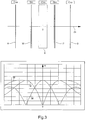
- FIG. 3 To the figure 3 is shown a variant of the arrangement of an antenna according to the invention.
- the position of the five coils 6, 8, 9, 16 and 17 is shown schematically in the upper drawing.
- the central spool 6 has 28 turns and extends along the axis 24 between -13.5 cm and 13.5 cm.
- the coils 8 and 9 are each formed of 18 turns and are respectively at -70 cm and + 70 cm.
- these three coils of the first group are traversed by a current of 1A.
- the two coils 16 and 17 of the second group each have 15 turns and are placed respectively at -30 cm and + 30 cm.
- the power supply of this second group is provided with 1.57 A.
- FIG. 5 schematically shows a second embodiment of the invention.
- the antenna 42 is formed by only four coils, namely a first group consisting of coils 44 and 46 and a second group consisting of coils 48 and 50.
- the amplitudes 52 and 54 generated respectively by the first and the second group of coils are represented.
- the resulting total magnetic field is given by curve 56 which corresponds to the quadratic sum of curves 52 and 54.
- the coils of the second group are energized in quadrature phase relative to the coils of the first group.
- the two coils of the same group are supplied with a phase shift of 180 ° so as to generate mutual shielding.
- the resulting amplitude 56 within the volume defined by the antenna 42 is substantially constant but has a slight variation.
- this second embodiment allows the economy of a coil but must be satisfied with a certain variation of field within the volume of the antenna, that is to say the active zone ZA of communication with transponders.
- such a relatively small variation with respect to the amplitude of the magnetic field H can be considered substantially constant.
- the antenna 42 is arranged as follows: the coil 46 extends from -70 cm to -39 cm and the coil 48 extends from -22 cm to 9 cm.
- the spool 44 extends from -9 cm to 22 cm and the spool 50 extends from 39 cm to 70 cm. All the coils are formed of 15 turns and are powered by an electric current of 1 A. The amplitude curves given on the graph correspond to this numerical example.
Landscapes
- Near-Field Transmission Systems (AREA)
Claims (5)
- Leser oder Sender (22; 42), der dazu vorgesehen ist, mit Sendeempfängern zu kommunizieren, und eine Antenne umfasst, die aus einer Mehrzahl von Windungen gebildet ist, die eine Mittelachse und ein Gesamt-Innenvolumen definieren, dadurch gekennzeichnet, dass diese Antenne eine mindestens zwei erste Spulen (6, 8, 9; 44, 46) bildende erste Gruppe von Windungen und eine zwei zweite Spulen (16, 17; 48, 50) bildende zweite Gruppe von Windungen umfasst, wobei diese erste und diese zweite Gruppe von Windungen mit Phasenquadratur gespeist werden und dafür ausgelegt sind, ein Gesamtmagnetfeld zu erzeugen, das im Wesentlichen auf der gesamten Länge (L) der Antenne entlang ihrer Mittelachse eine ungefähr konstante Amplitude besitzt und außerhalb dieser Antenne mit zunehmender Entfernung hiervon schnell abnimmt.
- Leser oder Sender nach Anspruch 1, wobei die erste Gruppe von Windungen aus drei Spulen (6, 8, 9) gebildet ist, wovon eine eine mittlere Spule (6) ist und zwei Randspulen (8, 9) jeweils entsprechend an den beiden Enden der Antenne angeordnet sind, wobei die mittlere Spule mit einer Phasenverschiebung von 180° in Bezug auf die beiden Randspulen gespeist wird, dadurch gekennzeichnet, dass die zweite Gruppe von Windungen aus zwei Ausgleichsspulen (16 und 17) gebildet ist, die zwischen der mittleren Spule und jeweils entsprechend den beiden Randspulen angeordnet sind, derart, dass die Abnahme oder das Verschwinden des Magnetfeldes zwischen der mittleren Spule und den beiden Randspulen ausgeglichen wird, was als Abschirmung dieser mittleren Spule dient, wobei die beiden Ausgleichsspulen mit einer Phasenverschiebung von 180° gespeist werden.
- Leser oder Sender nach Anspruch 1, dadurch gekennzeichnet, dass die erste Gruppe von Windungen aus zwei Spulen (44 und 46) gebildet ist, die mit einer Phasenverschiebung von 180° gespeist werden, und dass die zweite Gruppe von Windungen aus zwei Spulen (48 und 50) gebildet ist, die ebenfalls mit einer Phasenverschiebung von 180° gespeist werden, wobei die beiden Spulen der ersten Gruppe in einem bestimmten Abstand voneinander angeordnet sind, wobei dieser Abstand im Wesentlichen gleich jenem ist, der die beiden Spulen der zweiten Gruppe trennt, wobei diese erste und diese zweite Gruppe relativ zueinander in einer Weise positioniert sind, dass jede dieser Gruppen die Abnahme oder das Verschwinden des Magnetfeldes zwischen den beiden Spulen der anderen Gruppe ausgleicht.
- Leser oder Sender nach Anspruch 2, dadurch gekennzeichnet, dass die erste Gruppe von Windungen mit einem elektrischen Strom mit einem Wert, der kleiner als jener des Stroms ist, der in der zweiten Gruppe von Windungen fließt, gespeist wird, wobei die Anzahl von Windungen jeder Spule so vorgesehen ist, dass das Gesamtmagnetfeld innerhalb des Gesamt-Innenvolumens der Antenne im Wesentlichen konstant ist.
- Leser oder Sender nach Anspruch 3, dadurch gekennzeichnet, dass sich eine Spule (44) der ersten Gruppe von Windungen mit einer Spule (48) der zweiten Gruppe von Windungen teilweise überlappt.
Applications Claiming Priority (1)
| Application Number | Priority Date | Filing Date | Title |
|---|---|---|---|
| PCT/EP2002/012195 WO2004040698A1 (fr) | 2002-10-31 | 2002-10-31 | Lecteur ou emetteur et/ou recepteur equipe d'une antenne blindee |
Publications (2)
| Publication Number | Publication Date |
|---|---|
| EP1559170A1 EP1559170A1 (de) | 2005-08-03 |
| EP1559170B1 true EP1559170B1 (de) | 2017-11-29 |
Family
ID=32241232
Family Applications (1)
| Application Number | Title | Priority Date | Filing Date |
|---|---|---|---|
| EP02787538.4A Expired - Lifetime EP1559170B1 (de) | 2002-10-31 | 2002-10-31 | Abgeschirmte antenne für leser oder sender/empfänger |
Country Status (4)
| Country | Link |
|---|---|
| US (1) | US7098866B2 (de) |
| EP (1) | EP1559170B1 (de) |
| AU (1) | AU2002351813A1 (de) |
| WO (1) | WO2004040698A1 (de) |
Families Citing this family (11)
| Publication number | Priority date | Publication date | Assignee | Title |
|---|---|---|---|---|
| WO2008106552A1 (en) | 2007-02-28 | 2008-09-04 | Rf Surgical Systems, Inc. | Method, apparatus and article for detection of transponder tagged objects, for example during surgery |
| US7696877B2 (en) | 2007-05-01 | 2010-04-13 | Rf Surgical Systems, Inc. | Method, apparatus and article for detection of transponder tagged objects, for example during surgery |
| WO2009154987A2 (en) * | 2008-05-28 | 2009-12-23 | Rf Surgical Systems, Inc. | Method, apparatus and article for detection of transponder tagged objects, for example during surgery |
| US8264342B2 (en) | 2008-10-28 | 2012-09-11 | RF Surgical Systems, Inc | Method and apparatus to detect transponder tagged objects, for example during medical procedures |
| US9226686B2 (en) | 2009-11-23 | 2016-01-05 | Rf Surgical Systems, Inc. | Method and apparatus to account for transponder tagged objects used during medical procedures |
| EP3125804B1 (de) | 2014-03-31 | 2019-05-01 | Covidien LP | Tragbares kugelförmiges antennensystem zur detektion von transpondermarkierten objekten, etwa bei chirurgischen eingriffen |
| US9514341B2 (en) | 2014-03-31 | 2016-12-06 | Covidien Lp | Method, apparatus and article for detection of transponder tagged objects, for example during surgery |
| US9690963B2 (en) | 2015-03-02 | 2017-06-27 | Covidien Lp | Hand-held dual spherical antenna system |
| USD775331S1 (en) | 2015-03-02 | 2016-12-27 | Covidien Lp | Hand-held antenna system |
| US10193209B2 (en) | 2015-04-06 | 2019-01-29 | Covidien Lp | Mat based antenna and heater system, for use during medical procedures |
| US11620464B2 (en) | 2020-03-31 | 2023-04-04 | Covidien Lp | In-vivo introducible antenna for detection of RF tags |
Family Cites Families (5)
| Publication number | Priority date | Publication date | Assignee | Title |
|---|---|---|---|---|
| US5061941A (en) | 1990-02-01 | 1991-10-29 | Checkpoint Systems, Inc. | Composite antenna for electronic article surveillance systems |
| AU702622B2 (en) * | 1995-05-30 | 1999-02-25 | Sensormatic Electronics Corporation | EAS system antenna configuration for providing improved interrogation field distribution |
| JP3528367B2 (ja) * | 1995-09-30 | 2004-05-17 | ソニーケミカル株式会社 | リーダ・ライタ用アンテナ |
| US6307468B1 (en) * | 1999-07-20 | 2001-10-23 | Avid Identification Systems, Inc. | Impedance matching network and multidimensional electromagnetic field coil for a transponder interrogator |
| JP2001326526A (ja) * | 2000-05-16 | 2001-11-22 | Mitsubishi Electric Corp | シールドアンテナコイル |
-
2002
- 2002-10-31 US US10/533,444 patent/US7098866B2/en not_active Expired - Lifetime
- 2002-10-31 EP EP02787538.4A patent/EP1559170B1/de not_active Expired - Lifetime
- 2002-10-31 WO PCT/EP2002/012195 patent/WO2004040698A1/fr not_active Ceased
- 2002-10-31 AU AU2002351813A patent/AU2002351813A1/en not_active Abandoned
Also Published As
| Publication number | Publication date |
|---|---|
| AU2002351813A1 (en) | 2004-05-25 |
| US20060044208A1 (en) | 2006-03-02 |
| US7098866B2 (en) | 2006-08-29 |
| EP1559170A1 (de) | 2005-08-03 |
| WO2004040698A1 (fr) | 2004-05-13 |
Similar Documents
| Publication | Publication Date | Title |
|---|---|---|
| EP1559170B1 (de) | Abgeschirmte antenne für leser oder sender/empfänger | |
| FR2981519A1 (fr) | Dispositif de chargement inductif d'un appareil portable integrant une antenne de communication en champ proche | |
| EP2174269B1 (de) | Gesichertes dokument mit kontaktlosem chip und schutz von daten gegen unautorisierten zugriff | |
| EP0805507B1 (de) | Empfangs- und/oder Sendeeinrichtung für Funksprüche mit einer induktiven und kapazitiven Antenne | |
| EP0473497B1 (de) | Antennenvorrichtung zum Ausstrahlen und Empfangen von Hochfrequenzwellen | |
| EP0457880B1 (de) | Iff-bordantenne mit schaltbaren strahlungsdiagrammen | |
| EP0805512A1 (de) | Kompakt gedruckte Antenne mit geringer Strahlung in Elevationsrichtung | |
| EP0544576A1 (de) | Linear Servomotor mit veränderlicher Reluktanz | |
| EP1145379A1 (de) | Antenne mit einer filtermaterialanordnung | |
| EP0662666B1 (de) | Vorrichtung zur kontaktlosen Identifizierung von Objekten, insbesondere von metallischen Objekten | |
| FR3075523A1 (fr) | Detecteur double technologie comprenant un capteur inductif et un radar | |
| FR3103977A1 (fr) | Dispositif de communication en champ proche a haute frequence et de rechargement par induction d’un appareil electronique portable | |
| EP0860894A1 (de) | Miniatur-Resonanzantenne in Form von ringförmigen Streifenleiterantennen | |
| WO1999054687A1 (fr) | Dispositif de mesure incrementale de position | |
| EP3724679B1 (de) | Doppeldetektor mit querspulen | |
| FR2760133A1 (fr) | Antenne resonnante pour l'emission ou la reception d'ondes polarisees | |
| CA2937510A1 (fr) | Dispositif de communication d'une cabine d'aeronef | |
| WO2005103756A1 (fr) | Dispositif de detection comprenant un miroir parabolique, et utilisation d'un tel dispositif a bord d'un engin de survol | |
| EP0689301A1 (de) | Rundstrahlantennensystem mit Polarisationsdiversität und Winkeldiversität | |
| EP1058125A1 (de) | Antennenanordnung zum Empfangen von durch geostationären Satelliten ausgesendeten Signalen | |
| FR2813149A1 (fr) | Antenne de generation d'un champ electromagnetique pour transpondeur | |
| EP1351372A1 (de) | Induktiver Winkelgeber des Typs Synchroresolver | |
| EP0762534A1 (de) | Verfahren zur Verbreiterung des Strahlungsdiagramms einer Gruppenantenne mit verteilten Elementen in einem Volumen | |
| FR2792594A1 (fr) | Identifiant pour systeme d'acces dit mains libres | |
| FR2616549A1 (fr) | Dispositif de detection et de mesure de defauts de transmission de l'energie electrique dans les lignes polyphasees equilibrees |
Legal Events
| Date | Code | Title | Description |
|---|---|---|---|
| PUAI | Public reference made under article 153(3) epc to a published international application that has entered the european phase |
Free format text: ORIGINAL CODE: 0009012 |
|
| 17P | Request for examination filed |
Effective date: 20050531 |
|
| AK | Designated contracting states |
Kind code of ref document: A1 Designated state(s): AT BE BG CH CY CZ DE DK EE ES FI FR GB GR IE IT LI LU MC NL PT SE SK TR |
|
| AX | Request for extension of the european patent |
Extension state: AL LT LV MK RO SI |
|
| DAX | Request for extension of the european patent (deleted) | ||
| RBV | Designated contracting states (corrected) |
Designated state(s): CH DE FR GB IT LI |
|
| REG | Reference to a national code |
Ref country code: DE Ref legal event code: R079 Ref document number: 60249195 Country of ref document: DE Free format text: PREVIOUS MAIN CLASS: H01Q0007040000 Ipc: H01Q0001220000 |
|
| RIC1 | Information provided on ipc code assigned before grant |
Ipc: H01Q 1/22 20060101AFI20170515BHEP Ipc: H01Q 7/04 20060101ALI20170515BHEP |
|
| GRAP | Despatch of communication of intention to grant a patent |
Free format text: ORIGINAL CODE: EPIDOSNIGR1 |
|
| INTG | Intention to grant announced |
Effective date: 20170623 |
|
| GRAS | Grant fee paid |
Free format text: ORIGINAL CODE: EPIDOSNIGR3 |
|
| GRAA | (expected) grant |
Free format text: ORIGINAL CODE: 0009210 |
|
| AK | Designated contracting states |
Kind code of ref document: B1 Designated state(s): CH DE FR GB IT LI |
|
| REG | Reference to a national code |
Ref country code: GB Ref legal event code: FG4D Free format text: NOT ENGLISH |
|
| REG | Reference to a national code |
Ref country code: CH Ref legal event code: EP |
|
| REG | Reference to a national code |
Ref country code: DE Ref legal event code: R096 Ref document number: 60249195 Country of ref document: DE |
|
| REG | Reference to a national code |
Ref country code: CH Ref legal event code: NV Representative=s name: ICB INGENIEURS CONSEILS EN BREVETS SA, CH |
|
| REG | Reference to a national code |
Ref country code: DE Ref legal event code: R097 Ref document number: 60249195 Country of ref document: DE |
|
| PG25 | Lapsed in a contracting state [announced via postgrant information from national office to epo] |
Ref country code: IT Free format text: LAPSE BECAUSE OF FAILURE TO SUBMIT A TRANSLATION OF THE DESCRIPTION OR TO PAY THE FEE WITHIN THE PRESCRIBED TIME-LIMIT Effective date: 20171129 |
|
| REG | Reference to a national code |
Ref country code: FR Ref legal event code: PLFP Year of fee payment: 17 |
|
| PLBE | No opposition filed within time limit |
Free format text: ORIGINAL CODE: 0009261 |
|
| STAA | Information on the status of an ep patent application or granted ep patent |
Free format text: STATUS: NO OPPOSITION FILED WITHIN TIME LIMIT |
|
| 26N | No opposition filed |
Effective date: 20180830 |
|
| GBPC | Gb: european patent ceased through non-payment of renewal fee |
Effective date: 20181031 |
|
| PG25 | Lapsed in a contracting state [announced via postgrant information from national office to epo] |
Ref country code: GB Free format text: LAPSE BECAUSE OF NON-PAYMENT OF DUE FEES Effective date: 20181031 |
|
| PGFP | Annual fee paid to national office [announced via postgrant information from national office to epo] |
Ref country code: FR Payment date: 20200917 Year of fee payment: 19 |
|
| PGFP | Annual fee paid to national office [announced via postgrant information from national office to epo] |
Ref country code: CH Payment date: 20200917 Year of fee payment: 19 |
|
| PGFP | Annual fee paid to national office [announced via postgrant information from national office to epo] |
Ref country code: DE Payment date: 20200917 Year of fee payment: 19 |
|
| REG | Reference to a national code |
Ref country code: DE Ref legal event code: R119 Ref document number: 60249195 Country of ref document: DE |
|
| REG | Reference to a national code |
Ref country code: CH Ref legal event code: PL |
|
| PG25 | Lapsed in a contracting state [announced via postgrant information from national office to epo] |
Ref country code: DE Free format text: LAPSE BECAUSE OF NON-PAYMENT OF DUE FEES Effective date: 20220503 |
|
| PG25 | Lapsed in a contracting state [announced via postgrant information from national office to epo] |
Ref country code: LI Free format text: LAPSE BECAUSE OF NON-PAYMENT OF DUE FEES Effective date: 20211031 Ref country code: CH Free format text: LAPSE BECAUSE OF NON-PAYMENT OF DUE FEES Effective date: 20211031 |
|
| PG25 | Lapsed in a contracting state [announced via postgrant information from national office to epo] |
Ref country code: FR Free format text: LAPSE BECAUSE OF NON-PAYMENT OF DUE FEES Effective date: 20211031 |