EP1558820B1 - Shower trap - Google Patents
Shower trap Download PDFInfo
- Publication number
- EP1558820B1 EP1558820B1 EP03775533.7A EP03775533A EP1558820B1 EP 1558820 B1 EP1558820 B1 EP 1558820B1 EP 03775533 A EP03775533 A EP 03775533A EP 1558820 B1 EP1558820 B1 EP 1558820B1
- Authority
- EP
- European Patent Office
- Prior art keywords
- trap
- tube
- sleeve
- inlet
- shower
- Prior art date
- Legal status (The legal status is an assumption and is not a legal conclusion. Google has not performed a legal analysis and makes no representation as to the accuracy of the status listed.)
- Expired - Lifetime
Links
Images

Classifications
-
- E—FIXED CONSTRUCTIONS
- E03—WATER SUPPLY; SEWERAGE
- E03C—DOMESTIC PLUMBING INSTALLATIONS FOR FRESH WATER OR WASTE WATER; SINKS
- E03C1/00—Domestic plumbing installations for fresh water or waste water; Sinks
- E03C1/12—Plumbing installations for waste water; Basins or fountains connected thereto; Sinks
- E03C1/28—Odour seals
- E03C1/29—Odour seals having housing containing dividing wall, e.g. tubular
Definitions
- the present invention relates to an adjustable waste trap.
- the invention relates to an adjustable waste trap for use in shower trays, or other applications where cleaning access from above is desirable.
- a typical trap features a body which is located under the drain and is clamped to the shower tray by a threaded flanged collar which extends through the drain and engages a corresponding thread on the trap body. Alternatively, the collar may be clamped to the trap body by means of separate screws.
- the trap provides a water seal to prevent noxious gases from backing up the waste pipe and entering the shower enclosure.
- shower traps may be prone to becoming blocked or clogged due to shampoo residue and hair being washed into the trap.
- Conventional traps only permit access from beneath the trap, which given that many shower trays are of restricted height can make it very difficult if not impossible for users to access the trap for cleaning or maintenance purposes.
- a modified form of shower trap in which the water seal is provided by a tube which descends into the trap body from an inlet covered by a removable grid, and which tube is removable from the body through the inlet.
- the tube forms a water seal at the lower end thereof, and yet may be removed from the inlet when necessary, to permit access to the interior of the trap for cleaning and maintenance.
- the tube is locked into position by a bayonet-type fitting, by engaging a series of protrusions extending from a correspondingly shaped locking sleeve.
- the upper end of the tube is received within the sleeve, which is formed integrally with the body and extends into the body concentric with the inlet.
- This modified shower trap has disadvantages.
- the locking mechanism may be difficult to release and engage for individuals of restricted dexterity. Further, with use of the trap, the build up of material within the trap may make the locking mechanism still harder to use.
- the locking sleeve also extends across the trap outlet, formed in the side of the trap body, such that it is not possible to gain access to the outlet for cleaning.
- DE 297 11 690 U1 discloses a waste trap according to the preamble of claim 1, and in particular describes a waste trap comprising a housing 1 with an inlet and an outlet, a stand pipe 17 extending from the inlet into the housing. The stand pipe being removable through the inlet.
- the waste trap further comprises a dip pipe 11, support on a shoulder 13 defined by the housing. The dip pipe cooperates with the stand pipe to form a water seal within the housing when in use.
- CHA193865 discloses a siphon with an overflow pipe covered by a bell; with a liquid seal between the overflow pipe and the bell 10.
- the overflow pipe is sealed to an outer pipe by a conical seat.
- the sleeve and tube in combination provide a water seal, it is possible for the tube to be moved upwards or downwards relative to the sleeve without losing the water seal thereby formed.
- the axial location of the tube need not be fixed relative to the body, and the waste trap may be readily used with shower trays of different thicknesses.
- the provision of a sleeve which is fixed to the body and serves to locate the tube in the body allows the tube to be used without a separate locking ring, which both avoids the obstruction caused by the locking ring in existing shower traps, and makes it easier for users of restricted dexterity, and indeed any users, to remove the tube from the trap.
- the tube extends below the outlet on the body.
- the tube is vertically movable within the body.
- the tube may be generally freely movable, it is preferred that some form of retaining means is present to restrict the freedom of movement of the tube.
- the tube may be threaded and received in a correspondingly-threaded portion of the body; or the tube may be provided with a ratchet arrangement to restrict the freedom of movement.
- the tube is slidably received within a trap body retaining collar, which collar is itself externally threaded, or otherwise profiled, and engages with a cooperating thread profile provided on the trap body.
- the collar may be securable to the trap body by appropriate fasteners, or the like. The provision of such a collar allows the tube to be moved axially relatively straightforwardly, and if desired the tube may be withdrawn from the collar.
- the trap includes a flange on an upper portion thereof, for engaging with a shower tray or the like.
- the flange may be used to overlie a portion of a shower tray or flooring material, to clamp the tray to the trap.
- the flange may be located on the body of the trap, or on the tube, or collar if present.
- the sleeve is located towards a lower portion of the body; conveniently within the lowermost portion thereof.
- the sleeve is spaced from a lower surface of the body, to allow water outflow from within the sleeve.
- the sleeve is spaced from a lower surface of the body (12) by support pins and pin-receiving members.
- the sleeve receives an end of the tube. This arrangement effectively extends the length of the tube, so providing a relatively straightforward means whereby the location of the lower end of the tube may be varied without disrupting the water seal.
- the sleeve may be received within an end of the tube.
- the waste trap may be designed to be permanently open, for use with, for example, showers; or may be intended for use with a sealing mechanism such as a plug.
- An integral plug may be provided.
- the trap may further comprise a cover for restricting access to the interior of the trap.
- the cover may be in the form of a shield or dome member.
- the tube comprises a portion adapted to be gripped by a user for removal of the tube from the trap body.
- the tube comprises a portion of reduced diameter received within a portion of increased diameter.
- the tube is telescoped in order to adjust the length thereof.
- a portion of the tube may be freely movable under gravity, such that the tube automatically adjusts in length.
- the tube may be axially extendable, for example the tube may have at least a portion of wall of concertina-like form.
- the tube may be received within a trap body retaining collar, which collar is vertically movable within the trap body inlet. Conveniently the collar is threaded, and engages with a corresponding thread provided on the inlet. Thus, as the collar is moved vertically, the length of the tube may be adjusted correspondingly.
- the tube may be fixed within the collar, or may be removable therefrom.
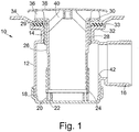
- FIG. 1 shows a shower trap 10 comprising a body 12 defining an inlet 14 and an outlet 16.
- the body is formed from two injection-moulded plastics parts, with the lower part 18 forming the lower end of the body 12.
- the lower part 18 of the body carries three spaced pin-receiving members 20, each of which receives a support pin 22 provided on the underside of a tubular sleeve member 24 which is disposed within the lower part of the body 12.
- the sleeve member 24 extends upward within the body 12 to a level slightly above the lower edge of the outlet 16.
- inlet tube 26 Extending into the body 12 from the inlet 14 is an inlet tube 26, the lower end of which is received in a snug fit within the sleeve member 24. In alternative embodiments of the invention, a snug fit may not be necessary, and a seal may be maintained simply by means of water within the trap.
- the upper end of the inlet tube 26 is received in a snug fit within an externally threaded upper collar member 28, which engages with a correspondingly-threaded portion of the inlet 14.
- a sealing O-ring 29 is carried in an annular groove in the upper portion of the tube 26 and engages with an inner face of the collar member 28.
- the threaded collar member 28 includes an upper flange 30, which cooperates with a corresponding flange 32 and seal 33 provided on the inlet 14 to clamp and engage with an edge of a shower tray drain opening 34.
- the flange 30 of the threaded collar member 28 also carries a series of six spaced supports 36 on which rest a metal domed shield member 38.
- the shield member 38 is attached to a spider 40 which is integral with the tube 26.
- the trap 10 may be adjusted and cleaned as follows.
- the threaded collar 28 is rotated to bring the collar 28 and the trap body 12 together and form a water-tight seal between the flanges 30, 32 and the shower tray 34.
- the shower tray 34 is thus clamped between the threaded collar 28 and the inlet 14.
- the shower tray may be clamped by securing the flanges 30, 32 together with separate fasteners, such as screw members.
- the extent to which the threaded collar 28 extends into the trap body 12 will vary depending upon a number of factors, including the thickness of the shower tray 34 and the seal 33; the extent to which the tube 26 extends into the body 12 will vary correspondingly, as will the extent to which the lower end of the tube 26 extends into the lower sleeve 24.
- the lower sleeve 24 and tube 26 are dimensioned such that the lower end of the tube is always within the sleeve, within the range of shower tray and seal dimensions normally encountered.
- the trap 10 of the present invention may easily accommodate shower trays of a range of thicknesses.
- the lower sleeve 24 may also be removed in the same manner, since the pins 22 are held only by an interference fit. The user may thus have relatively unrestricted access to the trap 10 as well as to the outlet 16, since the upper threaded collar 28 does not restrict access to the outlet, unlike other known shower traps.
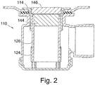
- FIG. 2 this shows a further embodiment of a shower trap in accordance with the present invention.
- the trap 110 functions in a similar manner to the trap of Figure 1 , with a tube 126 which is movable within a lower sleeve 124, and an adjustable threaded flanged collar 114 which may be used to clamp a shower tray to the body of the trap.
- the tube 126 further includes a crossbar 144 across the centre thereof at the upper end, and a conventional outlet grid 146 located above the crossbar 144. Adjustment of the collar 114 and tube 126 is carried out in the same manner as the trap of Figure 1 , while the crossbar 144 may be gripped and pulled upwards to remove the tube from the trap.
- the grid 146 may be either separate from the tube, and removed separately, or may be made integral therewith, and so may be grasped to remove the tube from the trap.
- FIG. 3 A further alternative trap is shown in Figure 3 .
- This trap 210 again operates in a similar manner to the previously-described traps, and further includes an overflow inlet 248 which may in use be connected to an overflow for a deep shower tray, bath, basin, or the like.
- the trap 210 includes a grid 246 set within the tube 226, with a 'clicker'-type plug 250 secured by threaded engagement with the grid 246.
- the plug 250 may be opened or closed with a simple depressing action, which adjusts the plug between an open and a closed position.
- This particular trap 210 may be used within bathtubs or deep shower trays requiring overflow outlets.
- the lower sleeve 24 may initially be mounted to the lower end of the tube 26, and the sleeve 24 and the tube 26 may be pushed together to the correct adjustment when the tube 26 is first pushed into the installed trap body 12.
- the sleeve 24 may fit within the tube 26.
- the lower sleeve 24 may be permanently mounted to the lower end of the tube 26, rather than to the base of the trap body, such that the tube and sleeve may act as a single telescoping unit for adjustment of tube length.
Landscapes
- Engineering & Computer Science (AREA)
- Environmental & Geological Engineering (AREA)
- Health & Medical Sciences (AREA)
- Life Sciences & Earth Sciences (AREA)
- Hydrology & Water Resources (AREA)
- Public Health (AREA)
- Water Supply & Treatment (AREA)
- Bathtubs, Showers, And Their Attachments (AREA)
- Sink And Installation For Waste Water (AREA)
- Jet Pumps And Other Pumps (AREA)
Applications Claiming Priority (3)
| Application Number | Priority Date | Filing Date | Title |
|---|---|---|---|
| GBGB0226069.3A GB0226069D0 (en) | 2002-11-08 | 2002-11-08 | Shower trap |
| GB0226069 | 2002-11-08 | ||
| PCT/GB2003/004890 WO2004042155A1 (en) | 2002-11-08 | 2003-11-10 | Shower trap |
Publications (2)
| Publication Number | Publication Date |
|---|---|
| EP1558820A1 EP1558820A1 (en) | 2005-08-03 |
| EP1558820B1 true EP1558820B1 (en) | 2017-12-13 |
Family
ID=9947448
Family Applications (1)
| Application Number | Title | Priority Date | Filing Date |
|---|---|---|---|
| EP03775533.7A Expired - Lifetime EP1558820B1 (en) | 2002-11-08 | 2003-11-10 | Shower trap |
Country Status (6)
| Country | Link |
|---|---|
| EP (1) | EP1558820B1 (pl) |
| AU (1) | AU2003283557A1 (pl) |
| GB (1) | GB0226069D0 (pl) |
| PL (1) | PL203720B1 (pl) |
| RU (1) | RU2005117632A (pl) |
| WO (1) | WO2004042155A1 (pl) |
Families Citing this family (8)
| Publication number | Priority date | Publication date | Assignee | Title |
|---|---|---|---|---|
| US8060956B2 (en) | 2005-08-02 | 2011-11-22 | Schluter Systems, L.P. | Shower drain adapter |
| US8112827B2 (en) | 2005-08-02 | 2012-02-14 | Schluter Systems L.P. | Shower drain adapter |
| US7992236B2 (en) | 2006-03-01 | 2011-08-09 | Schluter Systems, L.P. | Mock shower drain and associated methods |
| US8925123B2 (en) | 2006-03-01 | 2015-01-06 | Schluter Systems, L.P. | Segmented drain systems |
| USD593641S1 (en) | 2008-03-20 | 2009-06-02 | Schluler Systems L.P. | Adapter ring |
| DE102011051430B4 (de) * | 2011-06-29 | 2013-04-25 | Wedi Gmbh | Abwasserablauf mit Geruchsverschluss |
| JP6402886B2 (ja) * | 2013-12-27 | 2018-10-10 | Toto株式会社 | 浴室洗い場の排水部構造 |
| US11209108B2 (en) | 2018-09-10 | 2021-12-28 | Schluter Systems L.P. | Drain coupler with compressible seal |
Family Cites Families (5)
| Publication number | Priority date | Publication date | Assignee | Title |
|---|---|---|---|---|
| CH165442A (de) * | 1932-07-11 | 1933-11-30 | W Goldenbohm | Siphon für Wasch-, Spül- und Ausgussbecken. |
| CH193865A (de) | 1938-05-11 | 1937-11-15 | Ernst Fritz | Siphon mit Ölabschluss. |
| GB2301847B (en) * | 1995-06-06 | 1999-01-27 | Mcalpine & Co Ltd | Liquid sealing trap |
| DE29711690U1 (de) | 1997-07-03 | 1997-09-04 | Fa. Franz Viegener Ii, 57439 Attendorn | Ablaufventil |
| DE20019994U1 (de) * | 2000-11-21 | 2001-02-15 | Scherer, Norbert, 66773 Schwalbach | Becken- und Wannenablauf |
-
2002
- 2002-11-08 GB GBGB0226069.3A patent/GB0226069D0/en not_active Ceased
-
2003
- 2003-11-10 WO PCT/GB2003/004890 patent/WO2004042155A1/en not_active Ceased
- 2003-11-10 AU AU2003283557A patent/AU2003283557A1/en not_active Abandoned
- 2003-11-10 EP EP03775533.7A patent/EP1558820B1/en not_active Expired - Lifetime
- 2003-11-10 RU RU2005117632/03A patent/RU2005117632A/ru unknown
- 2003-11-10 PL PL375509A patent/PL203720B1/pl unknown
Also Published As
| Publication number | Publication date |
|---|---|
| WO2004042155A1 (en) | 2004-05-21 |
| AU2003283557A1 (en) | 2004-06-07 |
| EP1558820A1 (en) | 2005-08-03 |
| PL375509A1 (pl) | 2005-11-28 |
| GB0226069D0 (en) | 2002-12-18 |
| PL203720B1 (pl) | 2009-11-30 |
| RU2005117632A (ru) | 2006-01-20 |
Similar Documents
| Publication | Publication Date | Title |
|---|---|---|
| US7704386B2 (en) | Filter assembly | |
| GB2440811A (en) | Waste outlet for a shower | |
| CA2037236C (en) | Overflow and drain fittings for sanitary device | |
| US20120012510A1 (en) | Filter and filter assembly | |
| US20140166560A1 (en) | Removable locking floor sink drain screen for enlarged opening | |
| EP1558820B1 (en) | Shower trap | |
| EA008425B1 (ru) | Пробка для сливного отверстия | |
| EP3015611B1 (en) | Lavatory drain | |
| CA2620564C (en) | Fixture for disposing of bodily waste having an anti-overflow feature and a method for making the same | |
| GB2475413A (en) | Clogging resistant drain | |
| EP0906048B1 (en) | Remotely operated plug | |
| EP1446041B1 (en) | Washing platform | |
| US5893396A (en) | Height adjustable standpipe | |
| AU2002342142A1 (en) | Washing platform | |
| US6668393B1 (en) | Height adjustable diverter spout assembly | |
| AU2011100510A4 (en) | A water trap and a floor drain assembly including a water trap | |
| EP2967261B1 (en) | A bath or basin waste | |
| CZ197497A3 (cs) | Odtoková armatura | |
| EP3559357B1 (en) | A discharge system | |
| EP3825478B1 (en) | Drain strainer for a drainpipe | |
| JP7319224B2 (ja) | 排水口栓及び排水口栓付き槽体 | |
| JPH082210Y2 (ja) | 排水栓装置 | |
| EP0138796A1 (en) | Drain trap sanitary apparatus | |
| AU2007100030A4 (en) | Filter assembly | |
| AU2011100511B4 (en) | A water trap for mounting in a drain pipe |
Legal Events
| Date | Code | Title | Description |
|---|---|---|---|
| PUAI | Public reference made under article 153(3) epc to a published international application that has entered the european phase |
Free format text: ORIGINAL CODE: 0009012 |
|
| 17P | Request for examination filed |
Effective date: 20050512 |
|
| AK | Designated contracting states |
Kind code of ref document: A1 Designated state(s): AT BE BG CH CY CZ DE DK EE ES FI FR GB GR HU IE IT LI LU MC NL PT RO SE SI SK TR |
|
| AX | Request for extension of the european patent |
Extension state: AL LT LV MK |
|
| DAX | Request for extension of the european patent (deleted) | ||
| 17Q | First examination report despatched |
Effective date: 20100804 |
|
| STAA | Information on the status of an ep patent application or granted ep patent |
Free format text: STATUS: EXAMINATION IS IN PROGRESS |
|
| GRAP | Despatch of communication of intention to grant a patent |
Free format text: ORIGINAL CODE: EPIDOSNIGR1 |
|
| STAA | Information on the status of an ep patent application or granted ep patent |
Free format text: STATUS: GRANT OF PATENT IS INTENDED |
|
| INTG | Intention to grant announced |
Effective date: 20170601 |
|
| GRAS | Grant fee paid |
Free format text: ORIGINAL CODE: EPIDOSNIGR3 |
|
| GRAA | (expected) grant |
Free format text: ORIGINAL CODE: 0009210 |
|
| STAA | Information on the status of an ep patent application or granted ep patent |
Free format text: STATUS: THE PATENT HAS BEEN GRANTED |
|
| AK | Designated contracting states |
Kind code of ref document: B1 Designated state(s): AT BE BG CH CY CZ DE DK EE ES FI FR GB GR HU IE IT LI LU MC NL PT RO SE SI SK TR |
|
| REG | Reference to a national code |
Ref country code: GB Ref legal event code: FG4D |
|
| REG | Reference to a national code |
Ref country code: AT Ref legal event code: REF Ref document number: 954497 Country of ref document: AT Kind code of ref document: T Effective date: 20171215 Ref country code: CH Ref legal event code: EP |
|
| REG | Reference to a national code |
Ref country code: IE Ref legal event code: FG4D |
|
| REG | Reference to a national code |
Ref country code: DE Ref legal event code: R096 Ref document number: 60350846 Country of ref document: DE |
|
| REG | Reference to a national code |
Ref country code: NL Ref legal event code: MP Effective date: 20171213 |
|
| PG25 | Lapsed in a contracting state [announced via postgrant information from national office to epo] |
Ref country code: SE Free format text: LAPSE BECAUSE OF FAILURE TO SUBMIT A TRANSLATION OF THE DESCRIPTION OR TO PAY THE FEE WITHIN THE PRESCRIBED TIME-LIMIT Effective date: 20171213 Ref country code: FI Free format text: LAPSE BECAUSE OF FAILURE TO SUBMIT A TRANSLATION OF THE DESCRIPTION OR TO PAY THE FEE WITHIN THE PRESCRIBED TIME-LIMIT Effective date: 20171213 |
|
| REG | Reference to a national code |
Ref country code: AT Ref legal event code: MK05 Ref document number: 954497 Country of ref document: AT Kind code of ref document: T Effective date: 20171213 |
|
| PG25 | Lapsed in a contracting state [announced via postgrant information from national office to epo] |
Ref country code: BG Free format text: LAPSE BECAUSE OF FAILURE TO SUBMIT A TRANSLATION OF THE DESCRIPTION OR TO PAY THE FEE WITHIN THE PRESCRIBED TIME-LIMIT Effective date: 20180313 Ref country code: GR Free format text: LAPSE BECAUSE OF FAILURE TO SUBMIT A TRANSLATION OF THE DESCRIPTION OR TO PAY THE FEE WITHIN THE PRESCRIBED TIME-LIMIT Effective date: 20180314 |
|
| PG25 | Lapsed in a contracting state [announced via postgrant information from national office to epo] |
Ref country code: NL Free format text: LAPSE BECAUSE OF FAILURE TO SUBMIT A TRANSLATION OF THE DESCRIPTION OR TO PAY THE FEE WITHIN THE PRESCRIBED TIME-LIMIT Effective date: 20171213 |
|
| PG25 | Lapsed in a contracting state [announced via postgrant information from national office to epo] |
Ref country code: CZ Free format text: LAPSE BECAUSE OF FAILURE TO SUBMIT A TRANSLATION OF THE DESCRIPTION OR TO PAY THE FEE WITHIN THE PRESCRIBED TIME-LIMIT Effective date: 20171213 Ref country code: ES Free format text: LAPSE BECAUSE OF FAILURE TO SUBMIT A TRANSLATION OF THE DESCRIPTION OR TO PAY THE FEE WITHIN THE PRESCRIBED TIME-LIMIT Effective date: 20171213 Ref country code: EE Free format text: LAPSE BECAUSE OF FAILURE TO SUBMIT A TRANSLATION OF THE DESCRIPTION OR TO PAY THE FEE WITHIN THE PRESCRIBED TIME-LIMIT Effective date: 20171213 Ref country code: CY Free format text: LAPSE BECAUSE OF FAILURE TO SUBMIT A TRANSLATION OF THE DESCRIPTION OR TO PAY THE FEE WITHIN THE PRESCRIBED TIME-LIMIT Effective date: 20171213 Ref country code: SK Free format text: LAPSE BECAUSE OF FAILURE TO SUBMIT A TRANSLATION OF THE DESCRIPTION OR TO PAY THE FEE WITHIN THE PRESCRIBED TIME-LIMIT Effective date: 20171213 |
|
| PG25 | Lapsed in a contracting state [announced via postgrant information from national office to epo] |
Ref country code: RO Free format text: LAPSE BECAUSE OF FAILURE TO SUBMIT A TRANSLATION OF THE DESCRIPTION OR TO PAY THE FEE WITHIN THE PRESCRIBED TIME-LIMIT Effective date: 20171213 Ref country code: IT Free format text: LAPSE BECAUSE OF FAILURE TO SUBMIT A TRANSLATION OF THE DESCRIPTION OR TO PAY THE FEE WITHIN THE PRESCRIBED TIME-LIMIT Effective date: 20171213 Ref country code: AT Free format text: LAPSE BECAUSE OF FAILURE TO SUBMIT A TRANSLATION OF THE DESCRIPTION OR TO PAY THE FEE WITHIN THE PRESCRIBED TIME-LIMIT Effective date: 20171213 |
|
| REG | Reference to a national code |
Ref country code: DE Ref legal event code: R097 Ref document number: 60350846 Country of ref document: DE |
|
| PLBE | No opposition filed within time limit |
Free format text: ORIGINAL CODE: 0009261 |
|
| STAA | Information on the status of an ep patent application or granted ep patent |
Free format text: STATUS: NO OPPOSITION FILED WITHIN TIME LIMIT |
|
| 26N | No opposition filed |
Effective date: 20180914 |
|
| PG25 | Lapsed in a contracting state [announced via postgrant information from national office to epo] |
Ref country code: DK Free format text: LAPSE BECAUSE OF FAILURE TO SUBMIT A TRANSLATION OF THE DESCRIPTION OR TO PAY THE FEE WITHIN THE PRESCRIBED TIME-LIMIT Effective date: 20171213 |
|
| PG25 | Lapsed in a contracting state [announced via postgrant information from national office to epo] |
Ref country code: SI Free format text: LAPSE BECAUSE OF FAILURE TO SUBMIT A TRANSLATION OF THE DESCRIPTION OR TO PAY THE FEE WITHIN THE PRESCRIBED TIME-LIMIT Effective date: 20171213 |
|
| REG | Reference to a national code |
Ref country code: DE Ref legal event code: R119 Ref document number: 60350846 Country of ref document: DE |
|
| REG | Reference to a national code |
Ref country code: CH Ref legal event code: PL |
|
| PG25 | Lapsed in a contracting state [announced via postgrant information from national office to epo] |
Ref country code: MC Free format text: LAPSE BECAUSE OF FAILURE TO SUBMIT A TRANSLATION OF THE DESCRIPTION OR TO PAY THE FEE WITHIN THE PRESCRIBED TIME-LIMIT Effective date: 20171213 Ref country code: LU Free format text: LAPSE BECAUSE OF NON-PAYMENT OF DUE FEES Effective date: 20181110 |
|
| REG | Reference to a national code |
Ref country code: BE Ref legal event code: MM Effective date: 20181130 |
|
| REG | Reference to a national code |
Ref country code: IE Ref legal event code: MM4A |
|
| PG25 | Lapsed in a contracting state [announced via postgrant information from national office to epo] |
Ref country code: CH Free format text: LAPSE BECAUSE OF NON-PAYMENT OF DUE FEES Effective date: 20181130 Ref country code: LI Free format text: LAPSE BECAUSE OF NON-PAYMENT OF DUE FEES Effective date: 20181130 |
|
| PG25 | Lapsed in a contracting state [announced via postgrant information from national office to epo] |
Ref country code: FR Free format text: LAPSE BECAUSE OF NON-PAYMENT OF DUE FEES Effective date: 20181130 Ref country code: DE Free format text: LAPSE BECAUSE OF NON-PAYMENT OF DUE FEES Effective date: 20190601 Ref country code: IE Free format text: LAPSE BECAUSE OF NON-PAYMENT OF DUE FEES Effective date: 20181110 |
|
| PG25 | Lapsed in a contracting state [announced via postgrant information from national office to epo] |
Ref country code: BE Free format text: LAPSE BECAUSE OF NON-PAYMENT OF DUE FEES Effective date: 20181130 |
|
| PG25 | Lapsed in a contracting state [announced via postgrant information from national office to epo] |
Ref country code: TR Free format text: LAPSE BECAUSE OF FAILURE TO SUBMIT A TRANSLATION OF THE DESCRIPTION OR TO PAY THE FEE WITHIN THE PRESCRIBED TIME-LIMIT Effective date: 20171213 |
|
| PG25 | Lapsed in a contracting state [announced via postgrant information from national office to epo] |
Ref country code: PT Free format text: LAPSE BECAUSE OF FAILURE TO SUBMIT A TRANSLATION OF THE DESCRIPTION OR TO PAY THE FEE WITHIN THE PRESCRIBED TIME-LIMIT Effective date: 20171213 |
|
| PG25 | Lapsed in a contracting state [announced via postgrant information from national office to epo] |
Ref country code: HU Free format text: LAPSE BECAUSE OF FAILURE TO SUBMIT A TRANSLATION OF THE DESCRIPTION OR TO PAY THE FEE WITHIN THE PRESCRIBED TIME-LIMIT; INVALID AB INITIO Effective date: 20031110 |
|
| PGFP | Annual fee paid to national office [announced via postgrant information from national office to epo] |
Ref country code: GB Payment date: 20221128 Year of fee payment: 20 |
|
| REG | Reference to a national code |
Ref country code: GB Ref legal event code: PE20 Expiry date: 20231109 |
|
| PG25 | Lapsed in a contracting state [announced via postgrant information from national office to epo] |
Ref country code: GB Free format text: LAPSE BECAUSE OF EXPIRATION OF PROTECTION Effective date: 20231109 |
|
| PG25 | Lapsed in a contracting state [announced via postgrant information from national office to epo] |
Ref country code: GB Free format text: LAPSE BECAUSE OF EXPIRATION OF PROTECTION Effective date: 20231109 |