EP1558363B1 - Appareil et procede empechant la decomposition du germane - Google Patents
Appareil et procede empechant la decomposition du germane Download PDFInfo
- Publication number
- EP1558363B1 EP1558363B1 EP03777881A EP03777881A EP1558363B1 EP 1558363 B1 EP1558363 B1 EP 1558363B1 EP 03777881 A EP03777881 A EP 03777881A EP 03777881 A EP03777881 A EP 03777881A EP 1558363 B1 EP1558363 B1 EP 1558363B1
- Authority
- EP
- European Patent Office
- Prior art keywords
- germane
- gas
- activated carbon
- storage
- dispensing
- Prior art date
- Legal status (The legal status is an assumption and is not a legal conclusion. Google has not performed a legal analysis and makes no representation as to the accuracy of the status listed.)
- Expired - Lifetime
Links
- 229910000078 germane Inorganic materials 0.000 title claims abstract description 166
- 238000000034 method Methods 0.000 title claims description 22
- 238000000354 decomposition reaction Methods 0.000 title claims description 18
- 230000002401 inhibitory effect Effects 0.000 title description 2
- OKTJSMMVPCPJKN-UHFFFAOYSA-N Carbon Chemical compound [C] OKTJSMMVPCPJKN-UHFFFAOYSA-N 0.000 claims abstract description 149
- 239000002594 sorbent Substances 0.000 claims abstract description 139
- 238000003860 storage Methods 0.000 claims abstract description 77
- 238000004200 deflagration Methods 0.000 claims abstract description 43
- 239000007789 gas Substances 0.000 claims description 124
- 239000000463 material Substances 0.000 claims description 19
- 238000010438 heat treatment Methods 0.000 claims description 13
- 238000003795 desorption Methods 0.000 claims description 11
- UFHFLCQGNIYNRP-UHFFFAOYSA-N Hydrogen Chemical compound [H][H] UFHFLCQGNIYNRP-UHFFFAOYSA-N 0.000 claims description 9
- 239000011324 bead Substances 0.000 claims description 8
- 239000001257 hydrogen Substances 0.000 claims description 8
- 229910052739 hydrogen Inorganic materials 0.000 claims description 8
- 239000011261 inert gas Substances 0.000 claims description 8
- 230000001404 mediated effect Effects 0.000 claims description 8
- 230000008569 process Effects 0.000 claims description 6
- 238000010926 purge Methods 0.000 claims description 6
- 238000001816 cooling Methods 0.000 claims description 5
- 238000000197 pyrolysis Methods 0.000 claims description 4
- 239000008187 granular material Substances 0.000 claims description 3
- 239000008188 pellet Substances 0.000 claims description 3
- 239000013032 Hydrocarbon resin Substances 0.000 claims description 2
- 239000002131 composite material Substances 0.000 claims description 2
- 238000007599 discharging Methods 0.000 claims description 2
- 239000004744 fabric Substances 0.000 claims description 2
- 229920006270 hydrocarbon resin Polymers 0.000 claims description 2
- 150000002431 hydrogen Chemical class 0.000 claims description 2
- 239000012528 membrane Substances 0.000 claims description 2
- 239000000843 powder Substances 0.000 claims description 2
- 239000003826 tablet Substances 0.000 claims description 2
- 230000000717 retained effect Effects 0.000 abstract description 4
- 238000002203 pretreatment Methods 0.000 abstract 1
- 238000012360 testing method Methods 0.000 description 17
- 229910052799 carbon Inorganic materials 0.000 description 14
- 239000012530 fluid Substances 0.000 description 9
- 239000011148 porous material Substances 0.000 description 8
- WSWCOQWTEOXDQX-MQQKCMAXSA-M (E,E)-sorbate Chemical compound C\C=C\C=C\C([O-])=O WSWCOQWTEOXDQX-MQQKCMAXSA-M 0.000 description 7
- 239000003463 adsorbent Substances 0.000 description 7
- 229940075554 sorbate Drugs 0.000 description 7
- 239000012159 carrier gas Substances 0.000 description 6
- 230000002269 spontaneous effect Effects 0.000 description 6
- 230000000694 effects Effects 0.000 description 5
- 238000006243 chemical reaction Methods 0.000 description 4
- 238000004880 explosion Methods 0.000 description 4
- 239000004065 semiconductor Substances 0.000 description 4
- 230000008901 benefit Effects 0.000 description 3
- 239000003153 chemical reaction reagent Substances 0.000 description 3
- XPFVYQJUAUNWIW-UHFFFAOYSA-N furfuryl alcohol Chemical compound OCC1=CC=CO1 XPFVYQJUAUNWIW-UHFFFAOYSA-N 0.000 description 3
- 239000007943 implant Substances 0.000 description 3
- 150000002500 ions Chemical class 0.000 description 3
- 239000002245 particle Substances 0.000 description 3
- 239000000047 product Substances 0.000 description 3
- 238000012546 transfer Methods 0.000 description 3
- 229910021386 carbon form Inorganic materials 0.000 description 2
- 239000003575 carbonaceous material Substances 0.000 description 2
- 239000003610 charcoal Substances 0.000 description 2
- 230000008878 coupling Effects 0.000 description 2
- 238000010168 coupling process Methods 0.000 description 2
- 238000005859 coupling reaction Methods 0.000 description 2
- 229910052732 germanium Inorganic materials 0.000 description 2
- GNPVGFCGXDBREM-UHFFFAOYSA-N germanium atom Chemical compound [Ge] GNPVGFCGXDBREM-UHFFFAOYSA-N 0.000 description 2
- 239000001307 helium Substances 0.000 description 2
- 229910052734 helium Inorganic materials 0.000 description 2
- SWQJXJOGLNCZEY-UHFFFAOYSA-N helium atom Chemical compound [He] SWQJXJOGLNCZEY-UHFFFAOYSA-N 0.000 description 2
- 238000005468 ion implantation Methods 0.000 description 2
- 238000004519 manufacturing process Methods 0.000 description 2
- 238000002459 porosimetry Methods 0.000 description 2
- 238000012545 processing Methods 0.000 description 2
- GCLGEJMYGQKIIW-UHFFFAOYSA-H sodium hexametaphosphate Chemical compound [Na]OP1(=O)OP(=O)(O[Na])OP(=O)(O[Na])OP(=O)(O[Na])OP(=O)(O[Na])OP(=O)(O[Na])O1 GCLGEJMYGQKIIW-UHFFFAOYSA-H 0.000 description 2
- 229910001220 stainless steel Inorganic materials 0.000 description 2
- 239000010935 stainless steel Substances 0.000 description 2
- 235000013162 Cocos nucifera Nutrition 0.000 description 1
- 244000060011 Cocos nucifera Species 0.000 description 1
- 229920001328 Polyvinylidene chloride Polymers 0.000 description 1
- 230000003213 activating effect Effects 0.000 description 1
- 230000004913 activation Effects 0.000 description 1
- 230000009172 bursting Effects 0.000 description 1
- 239000002775 capsule Substances 0.000 description 1
- 239000007795 chemical reaction product Substances 0.000 description 1
- 239000003245 coal Substances 0.000 description 1
- 238000002485 combustion reaction Methods 0.000 description 1
- 238000004891 communication Methods 0.000 description 1
- 239000000470 constituent Substances 0.000 description 1
- 230000002596 correlated effect Effects 0.000 description 1
- 230000000875 corresponding effect Effects 0.000 description 1
- 230000007423 decrease Effects 0.000 description 1
- 230000007812 deficiency Effects 0.000 description 1
- 239000006185 dispersion Substances 0.000 description 1
- 238000009826 distribution Methods 0.000 description 1
- MYRTYDVEIRVNKP-UHFFFAOYSA-N divinylbenzene Substances C=CC1=CC=CC=C1C=C MYRTYDVEIRVNKP-UHFFFAOYSA-N 0.000 description 1
- 239000002019 doping agent Substances 0.000 description 1
- 239000002360 explosive Substances 0.000 description 1
- QUZPNFFHZPRKJD-UHFFFAOYSA-N germane Chemical compound [GeH4] QUZPNFFHZPRKJD-UHFFFAOYSA-N 0.000 description 1
- 229910052986 germanium hydride Inorganic materials 0.000 description 1
- 238000005247 gettering Methods 0.000 description 1
- 230000020169 heat generation Effects 0.000 description 1
- 239000012535 impurity Substances 0.000 description 1
- 238000011068 loading method Methods 0.000 description 1
- 239000011159 matrix material Substances 0.000 description 1
- 230000007246 mechanism Effects 0.000 description 1
- QSHDDOUJBYECFT-UHFFFAOYSA-N mercury Chemical compound [Hg] QSHDDOUJBYECFT-UHFFFAOYSA-N 0.000 description 1
- 229910052753 mercury Inorganic materials 0.000 description 1
- 238000012986 modification Methods 0.000 description 1
- 230000004048 modification Effects 0.000 description 1
- 238000004806 packaging method and process Methods 0.000 description 1
- 238000002161 passivation Methods 0.000 description 1
- 239000003208 petroleum Substances 0.000 description 1
- 239000011295 pitch Substances 0.000 description 1
- 229920002401 polyacrylamide Polymers 0.000 description 1
- 229920002239 polyacrylonitrile Polymers 0.000 description 1
- 239000005033 polyvinylidene chloride Substances 0.000 description 1
- 238000004445 quantitative analysis Methods 0.000 description 1
- 230000000246 remedial effect Effects 0.000 description 1
- 230000004044 response Effects 0.000 description 1
- 241000894007 species Species 0.000 description 1
- 239000012798 spherical particle Substances 0.000 description 1
- 230000002459 sustained effect Effects 0.000 description 1
- 238000009997 thermal pre-treatment Methods 0.000 description 1
- 238000011144 upstream manufacturing Methods 0.000 description 1
- 239000002023 wood Substances 0.000 description 1
Images


Classifications
-
- B—PERFORMING OPERATIONS; TRANSPORTING
- B01—PHYSICAL OR CHEMICAL PROCESSES OR APPARATUS IN GENERAL
- B01D—SEPARATION
- B01D53/00—Separation of gases or vapours; Recovering vapours of volatile solvents from gases; Chemical or biological purification of waste gases, e.g. engine exhaust gases, smoke, fumes, flue gases, aerosols
- B01D53/02—Separation of gases or vapours; Recovering vapours of volatile solvents from gases; Chemical or biological purification of waste gases, e.g. engine exhaust gases, smoke, fumes, flue gases, aerosols by adsorption, e.g. preparative gas chromatography
- B01D53/04—Separation of gases or vapours; Recovering vapours of volatile solvents from gases; Chemical or biological purification of waste gases, e.g. engine exhaust gases, smoke, fumes, flue gases, aerosols by adsorption, e.g. preparative gas chromatography with stationary adsorbents
-
- B—PERFORMING OPERATIONS; TRANSPORTING
- B01—PHYSICAL OR CHEMICAL PROCESSES OR APPARATUS IN GENERAL
- B01D—SEPARATION
- B01D59/00—Separation of different isotopes of the same chemical element
- B01D59/22—Separation by extracting
- B01D59/26—Separation by extracting by sorption, i.e. absorption, adsorption, persorption
-
- B—PERFORMING OPERATIONS; TRANSPORTING
- B01—PHYSICAL OR CHEMICAL PROCESSES OR APPARATUS IN GENERAL
- B01D—SEPARATION
- B01D2253/00—Adsorbents used in seperation treatment of gases and vapours
- B01D2253/10—Inorganic adsorbents
- B01D2253/102—Carbon
-
- B—PERFORMING OPERATIONS; TRANSPORTING
- B01—PHYSICAL OR CHEMICAL PROCESSES OR APPARATUS IN GENERAL
- B01D—SEPARATION
- B01D2259/00—Type of treatment
- B01D2259/40—Further details for adsorption processes and devices
- B01D2259/40083—Regeneration of adsorbents in processes other than pressure or temperature swing adsorption
- B01D2259/40086—Regeneration of adsorbents in processes other than pressure or temperature swing adsorption by using a purge gas
-
- B—PERFORMING OPERATIONS; TRANSPORTING
- B01—PHYSICAL OR CHEMICAL PROCESSES OR APPARATUS IN GENERAL
- B01D—SEPARATION
- B01D2259/00—Type of treatment
- B01D2259/40—Further details for adsorption processes and devices
- B01D2259/40083—Regeneration of adsorbents in processes other than pressure or temperature swing adsorption
- B01D2259/40088—Regeneration of adsorbents in processes other than pressure or temperature swing adsorption by heating
-
- B—PERFORMING OPERATIONS; TRANSPORTING
- B01—PHYSICAL OR CHEMICAL PROCESSES OR APPARATUS IN GENERAL
- B01D—SEPARATION
- B01D2259/00—Type of treatment
- B01D2259/45—Gas separation or purification devices adapted for specific applications
- B01D2259/4525—Gas separation or purification devices adapted for specific applications for storage and dispensing systems
-
- Y—GENERAL TAGGING OF NEW TECHNOLOGICAL DEVELOPMENTS; GENERAL TAGGING OF CROSS-SECTIONAL TECHNOLOGIES SPANNING OVER SEVERAL SECTIONS OF THE IPC; TECHNICAL SUBJECTS COVERED BY FORMER USPC CROSS-REFERENCE ART COLLECTIONS [XRACs] AND DIGESTS
- Y10—TECHNICAL SUBJECTS COVERED BY FORMER USPC
- Y10S—TECHNICAL SUBJECTS COVERED BY FORMER USPC CROSS-REFERENCE ART COLLECTIONS [XRACs] AND DIGESTS
- Y10S95/00—Gas separation: processes
- Y10S95/90—Solid sorbent
- Y10S95/901—Activated carbon
Definitions
- the present invention relates to apparatus and method for inhibiting decomposition of germane, and to semiconductor process systems including such apparatus and arranged to carry out such method.
- Germane (GeH 4 ) is a highly reactive gas that is susceptible to spontaneous decomposition. Depending on the speed of the reaction, the spontaneous decomposition of germane can lead to deflagration (sub-sonic reaction) or explosion (supersonic reaction).
- Spontaneous decomposition of germane in a sealed package may lead to very rapid increase in pressure and temperature in the package.
- runaway increases in pressure and temperature may occur, which exceed the corresponding thermal and baric limits of the package, resulting in bursting of the package and dispersion of germane into the ambient environment.
- germane is very useful in semiconductor manufacturing as a source reagent for germanium (Ge), e.g., as a dopant or bulk component in semiconductor films and materials
- germane is very useful in semiconductor manufacturing as a source reagent for germanium (Ge)
- the risk of fire and explosion attendant its use have caused other, less suitable Ge source reagent to be employed, or alternatively, double-containment vessels, flame arrestor systems and other safety equipment must be employed to ensure that the risk of spontaneous decomposition does not jeopardize the semiconductor manufacturing facility and its operating personnel.
- US patent number 5, 704,965 describes a method for storing and dispensing sorbable gases such as germane (among others) comprising loading the gas on a carbon sorbent material but fails to teach a process to render the carbon sorbent material deflagration resistant jn relation to germane gas absorbed therein.
- PCT patent application number WO 02/051525 A1 discloses methods for removing impurities from inert and non-reactive gases and fluids using preconditioned ultra-low emission carbon materials. The application fails to address the problem of substantially reducing the risk and consequences of spontaneous decomposition of germane gas when contained in a gas storage and dispensing vessel.
- the present invention relates generally to apparatus and method for providing germane in a manner that substantially reduces the risk and consequences of spontaneous decomposition of germane gas.
- the invention relates to a germane storage and delivery system, including:
- the invention relates to a germane storage and dispensing method comprising:
- the deflagration-resistance of the activated carbon sorbent medium and the conditions under which free germane gas in the interior volume of the gas storage and dispensing vessel undergoes deflagration, is measured at a temperature of 65°C and a pressure of 650 torr.
- the invention relates to a method of preparing an activated carbon sorbent material for use, such method comprising:
- FIG. 1 is a schematic representation of a germane deflagration test apparatus.
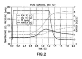
- FIG. 2 is a graph of temperature, in degrees Centigrade, pressure, in psig, and ignitor voltage, as a function of time, in seconds, for free germane deflagration, generated by the test apparatus schematically shown in FIG. 1 .
- FIG. 3 is a schematic representation of another germane deflagration test apparatus wherein germane is adsorbed on a carbon adsorbent material.
- FIG. 4 is a graph of temperature, in degrees Centigrade, pressure, in psig, and ignitor voltage, as a function of time, in seconds, for free germane deflagration, generated by the test apparatus schematically shown in FIG. 3 .
- FIG. 5 is a schematic representation of a germane storage and dispensing apparatus according to one embodiment of the present invention.
- the present invention is based on the discovery that germane may be stored in a physically adsorbed state in a fluid storage and dispensing vessel, on a sorbent medium comprising an activated carbon sorbent that has been subjected to pretreatment in a manner more fully described hereinafter, so that the fluid storage and dispensing vessel contains the sorbent with germane sorptively retained thereon, as well as free germane, and that such storage of germane gas provides surprising and unexpected anti-deflagrative stability.
- the present invention when practiced with gas storage and dispensing vessels of the type disclosed and claimed in U.S. Patent No. 5,518,528 issued May 21, 1996 in the names of Glenn M. Tom, et al. , featuring a vessel including a gas dispensing assembly coupled thereto, in which the vessel contains in the interior volume thereof a physical sorbent medium holding a sorbed gas thereon, permits the storage of germane at low pressures, since the vapor pressure of the adsorbed germane gas on the sorbent medium is negligible in relation to ambient (atmospheric) pressure.
- the low vapor pressure of the adsorbed gas means that the only contribution to the interior pressure of the gas storage vessel is from the free gas in the interstices of the sorbent bed particles in the vessel, and from the free gas in the head space of the vessel.
- a sufficient quantity of activated carbon sorbent medium is required in the gas storage and dispensing vessel, so that the amount of adsorbed germane gas is substantially greater than the amount of free germane gas in the interior volume of the vessel. Consistent with this objective, it is preferred that at least 30% of the interior volume of the vessel is occupied by the activated carbon sorbent medium, more preferably at least 75% of such volume, and most preferably at least 90% of the interior volume of the gas storage and dispensing vessel.
- the dispensing operation may be carried out in any suitable manner, including the heating of the vessel and sorbent bed therein, so that germane is thermally desorbed from the sorbent particles of activated carbon in the vessel, or alternatively by entrainment in a carrier gas that is flowed through the adsorbent bed, as described in U.S. Patent 5,980,608 issued November 9, 1999 in the names of James Dietz and James V. McManus .By such flow of carrier gas through the vessel, a mass transfer concentration gradient driving force is established, and the resulting desorption of the gas into the carrier gas provides a product gas stream that can be modulated by the flow, temperature and pressure of the carrier gas flow, to achieve a specific concentration of the germane in the carrier gas.
- the germane gas is dispensed by a pressure difference upon actuating the dispensing assembly coupled with the vessel to open a flow control valve therein (e.g., a valve in a valve head assembly connected to the neck of the vessel), so that the pressure differential mediates the desorption of the germane from the activated carbon sorbent medium.
- a flow control valve e.g., a valve in a valve head assembly connected to the neck of the vessel
- the invention is also applicable to gas storage and dispensing systems of the type described in U.S. Patent No. 6,089,027 issued July 18, 2000 in the names of Luping Wang and Glenn M . Tom, wherein the gas storage and dispensing vessel contains a pressure regulator upstream of a flow control valve, so that dispensed fluid is flowed through the pressure regulator prior to flow through the flow control valve, and wherein the vessel holds activated carbon sorbent material sorptively retaining germane thereon.
- the pressure regulator may be interiorly disposed in the vessel, so that moving parts of the regulator assembly, particularly when the regulator is adjustable in character, may occasion the incidence of spark or heat generation during their movement which can produce deflagration conditions in the vessel. As empirically shown more fully hereinafter, such deflagration may occur with the headspace gas (free germane), but will not propagate into the adsorbed gas inventory of the vessel.
- the gas storage and dispensing vessel may contain, in addition to the sorbent medium sorptively retaining the germane gas, a quantity of a hydrogen getter, e.g., in a capsule including a hydrogen-permeable membrane, so that any decomposition of the germane gas, e.g., during deflagration of head space gas, is chcmisorbed by the hydrogen getter, so that pressure increases incident to decomposition are minimized.
- Hydrogen gettering devices of such type are more fully described in U.S. Patent No. 6,132,492 issued October 17, 2000 in the names of Steven J. Hultquist, et al.
- the interior volume of the storage and dispensing vessel may have disposed in the interior volume thereof a hydrogen sensor, which upon sensing of evolved hydrogen gas in the interior volume incident to decomposition of germane therein, emits a control signal that may be sent to a microprocessor or central processing unit, to monitor the presence of hydrogen gas and the extent of decomposition of germane in the vessel, so that remedial action can be taken.
- the pretreatment of the activated carbon sorbent in the practice of the invention involves treating the physical sorbent material to desorb from the sorbent material extraneous sorbables, by steps such as:
- the sorbent material in the broad practice of the present invention may be pretreated, activated or processed in any suitable manner, as necessary or desired, to yield a sorbent medium of the desired form and performance characteristics, e.g., sorptive capacity, porosity, residual heels, etc., for use in the gas storage and dispensing system of the invention.
- the sorbent material may be subjected to a thermal pretreatment process involving exposure to selected activating and/or passivating gases at elevated temperatures, with intermittent and/or successive evacuation and inert purging steps.
- the sorbent medium employed in the gas storage and dispensing system comprises an activated carbon that is pretreated in accordance with the following procedure.
- the activated carbon sorbent first is cyclically purged with helium or other inert gas and evacuated, following which the sorbent is heated under vacuum to elevated temperature, e.g., a temperature on the order of 250°C, and vacuum baked for an extended period of time, such as 18 hours, to eliminate any moisture content of the sorbent.
- elevated temperature e.g., a temperature on the order of 250°C
- a predetermined amount of germane e.g., about 2% by weight of germane, based on the weight of the sorbent.
- the resulting sorbent and gas are then sealed in a vessel and heated to about 200°C, while pressure is monitored. This effects passivation of overly active sites.
- the temperature is held at 200°C until pressure stops increasing and for a predetermined additional period of time, e.g., 1 day.
- the vessel is evacuated at 200°C for about 4 hours and then cooled to room temperature under vacuum.
- the sorbent in the vessel at the conclusion of such cooling can be loaded with germane gas.
- the pretreatment procedure illustratively described above for an exemplary activated carbon sorbent may be significantly varied in practice, depending on the character of the specific sorbent utilized, and that other steps may be required or usefully employed in specific instances, to provide the sorbent in a form suitable for storage and dispensing of germane.
- activation of carbon sorbent media may be employed, or thermal processing to vary the pore size and/or pore size distribution, or other steps of a type and character that are useful in the specific circumstances and/or for the specific materials employed.
- the sorbent material used in the practice of the invention comprises a carbonaceous adsorbent medium.
- carbonaceous in reference to the physical sorbent material of the invention, means that the sorbent material comprises elemental carbon as its major component in the sorbent mass.
- Preferred forms of carbon sorbent materials include: carbon formed by pyrolysis of synthetic hydrocarbon resins such as polyacrylonitrile, polyacrylamides, sulfonated polystryrene-divinylbenzene, polyvinylidene chloride, furfuryl alcohol, etc.; cellulosic char; charcoal; activated carbon formed from natural source materials such as coconut shells, pitch, wood, petroleum, coal, etc.
- the carbon sorbent material may be activated by heating granulated charcoal to appropriate elevated temperature.
- Most preferred are the so-called bead carbon forms of activated carbon, where the beads, i.e., highly uniform diameter spherical particles, may have a diameter in the range of from about 0.1 to about 1 centimeter, and more preferably from about 0.25 to about 2 millimeters diameter, as well as other high fill density microporous carbon forms.
- carbon sorbent materials which are preferred in the broad practice of the invention include bead carbon materials designated as BAC-MP, BAC-LP, and BAC-G-70R, available from Kreha Corporation of America, New York, NY; Ambersorb 00 carbonaceous sorbents commercially available from Rohm & Haas Company, Philadelphia, PA as grades Ambersorb ® 563, Ambersorb ® 564, Ambersorb ® 348F, Ambersorb ® 575, Ambersorb ® 572, and Ambersorb ® 1500; Calgon Filtrasorb 400 ® and BPL GAC carbon sorbent materials commercially available from Calgon Carbon Corporation; and bead activated carbon sorbent materials commercially available from Blucher GmbH, Erkrath, Germany.
- the aforementioned Ambersorb materials have substantial pore volume in pores greater than 50 Angstroms, and in general such large pore sized materials are less preferred than those having pores not exceeding about 40 Angstroms.
- the sorbent used in the storage and dispensing system of the invention may have any suitable size, shape and conformation appropriate to the end use application and the specific sorbate fluid species involved.
- the sorbent material may for example be in the form of beads, granules, pellets, tablets, powders, particulates, extrudates, cloth or web form materials, honeycomb matrix monolith, composites (of the carbon sorbent with other components), or comminuted or crushed forms of the foregoing conformations.
- the storage and delivery system of the present invention may usefully consist of a standard gas cylinder, and a cylinder valve or other flow dispensing assembly (regulators, monitors, sensors, flow directing means, pressure controllers, mass flow controllers, piping, valving, instrumentation, automatic start and shut-off devices, etc.) coupled to the cylinder, with the cylinder holding the sorbent material, and wherein the cylinder is filled, e.g., to 1 atmosphere pressure, with germane gas.
- a cylinder valve or other flow dispensing assembly regulators, monitors, sensors, flow directing means, pressure controllers, mass flow controllers, piping, valving, instrumentation, automatic start and shut-off devices, etc.
- Fluid flow from the storage and delivery system of the invention by pressure differential desorption may be readily carried out by utilizing a pressure differential between the pressure in the interior volume of the storage and delivery system and a lower pressure exterior to the sorbent-containing vessel.
- Germane gas may be held in the germane storage and dispensing vessel at any suitable pressure, as for example a pressure in a range from about 10 to about 750 torr, or alternatively, greater pressures (e.g., superatmospheric pressures, such as up to about 50 psig) or lesser pressures may be employed.
- a pressure in a range from about 10 to about 750 torr or alternatively, greater pressures (e.g., superatmospheric pressures, such as up to about 50 psig) or lesser pressures may be employed.
- the benefit of the activated carbon sorbent medium in the germane storage and dispensing vessel is that the germane gas may be retained in a substantial volume at low pressure in the adsorbed state.
- the sorbent-containing vessel may hold germane gas at a subatmospheric pressure, e.g., 600 Torr, for use in an ion implantation process, where the ion implant chamber for implanting the germanium constituent is maintained under vacuum conditions or alternatively at low pressure, e.g., below 100 Torr, below the pressure of the interior volume in the storage and dispensing vessel.
- germane gas will desorb from the sorbent in the vessel and flow to the ion implant chamber, when gas flow communication is established between the ion implant chamber and the storage and dispensing vessel containing the sorbate germane gas.
- the storage and dispensing system thus effects flow of the germane gas through the connecting piping, valving and instrumentation, and is readily controllable at a desired flow rate.
- a device such as a mass flow controller, a constant flow can be achieved as the sorbent vessel pressure decreases with continued dispensing operation.
- the gas dispensing assembly of the storage and dispensing system of the invention may include means for heating the sorbent material, to thermally desorb sorbate fluid therefrom.
- heating means may include any suitable heat transfer or heat exchange devices, structures or apparatus, which are operatively associated with the sorbent material to effect heating thereof, for thermal desorption of the sorbate from the sorbent medium.
- the present invention contemplates heat- and/or pressure-mediated dispensing of germane from the sorbent on which same is stored.
- the specific activated carbon sorbent materials used in the practice of the invention, and their pore size, pore volume, and surface area characteristics may be widely varied in the broad practice of the present invention.
- the skilled artisan may readily determine suitable sorbent characteristics for a given end use application of the storage and dispensing system of the present invention without undue experimentation using surface area and porosity determinations, e.g., with mercury porosimetry techniques, and affinity studies for the particular fluid sought to be stored on and dispensed from the particular candidate sorbent material.
- the test apparatus 10 included a stainless steel pressure vessel 12 coupled to a germane source 14 by means of feed conduit 16 communicating with the interior volume 18 of the vessel.
- the vessel also included a gas discharge line 20 coupled to a vacuum pump (not shown).
- an ignition coil 22 joined to electrical leads 24 and 26, as shown, extending through the cover of the closed vessel 12.
- the vessel 12 was also equipped with a mid-vessel temperature sensor 30, a top-end temperature sensor 32, as well as a pressure transducer 28 for sensing the pressure in the interior volume of the vessel.
- temperature sensors (thermocouples) 30 and 32 and the fast-response pressure transducer 28 monitored the temperature and pressure conditions in the interior volume 18 of the vessel as the hot filament of the heating coil 22 was subjected to a voltage of 6.5 volts and initiated deflagration of the germane flowed into the vessel from source 14, with the gas being removed from the vessel in the discharge line 20. Prior to ignition, a pressure of 650 torr of germane was maintained in the vessel.
- FIG. 2 is a graph of temperature, in degrees Centigrade, pressure, in psig, and ignitor voltage, as a function of time, in seconds, for the free germane deflagration, generated by the test apparatus schematically shown in FIG. 1 .
- the ignition-mediated pressure increase was over five times the original 650 torr pressure, to 70 psig, and temperature reached a maximum of 210 °C.
- the deflagration test apparatus 50 shown in FIG. 3 comprised a stainless steel vessel 52 enclosed by a top cover to define an interior volume 54 therewithin.
- test vessel interior volume was 90% filled with the sorbent medium having germane adsorbed thereon, with the headspace occupying the remaining 10% of the interior volume of the vessel.
- the activated carbon sorbent was pretreated before being placed in the interior volume of the vessel, as described previously herein.
- thermocouple temperature sensor 68 In the interior volume of the vessel was disposed an ignition coil 60 connected to electrical leads 62 and 64, as shown.
- the interior volume pressure condition was monitored by a fast-action pressure transducer 66, and the temperatures in the interior volume were monitored at the lower end, mid-section and upper end of the sorbent bed by thermocouple temperature sensor 68 and the temperature of the vessel headspace was monitored by thermocouple temperature sensor 70.
- FIG. 4 is a graph of temperature, in degrees Centigrade, pressure, in psig, and ignitor voltage, as a function of time, in seconds, for free germane deflagration, generated by the test apparatus schematically shown in FIG. 3 .
- FIG. 5 is a schematic representation of a germane storage and dispensing apparatus according to one embodiment of the present invention.
- the gas storage and dispensing system 110 includes a gas storage and dispensing vessel 112 which may be in the form of a conventional gas cylinder with a cylindrical wall 114 enclosing an interior volume.
- an activated carbon physical sorbent material 116 In the interior volume of the vessel 112 is disposed an activated carbon physical sorbent material 116.
- the sorbent material is typically employed in a finely divided form, such as pellets, beads, granules, or the like, to provide a bed of the sorbent material having high surface area as measured by standard porosimetry (e.g., Brunnauer-Emmit-Teller) methodology.
- the gas storage and dispensing vessel 112 is of elongate character as shown, with a neck 118 to which is joined a valve head assembly 120, which in the embodiment shown includes a unitary block valve body 124, having a hand wheel 126 coupled thereto for manual opening and closure of the valve in the valve body.
- the valve body 124 has a coupling 126(a), such as a VCR connector, associated therewith, for dispensing of germane gas desorbed from the sorbent material in the gas storage and dispersing vessel, when the hand wheel 126 is turned to open the valve in the valve body 124.
- the germane gas may be released from the gas storage and dispensing container, when the exterior pressure of the downstream dispensing locus is below the pressure of the interior volume of the vessel 112, as for example is the case in ion implantation applications, in which the downstream ionizer is maintained at very low pressure conditions.
- the coupling 126(a) may join the gas storage and dispensing vessel 112 to a manifold or flow circuit containing a pump, blower, ejector, educator, compressor, fan, cryopump, pressure-building circuit, or other motive fluid impeller device serving to extract the germane sorbate gas from the sorbent material bed in the vessel 112.
- the vessel 112 or the sorbent material therein may be directly or indirectly heated to effect thermal desorption of the dispensing gas from the sorbent material in the vessel.
- the vessel 112 may be disposed in a heating jacket (not shown), or have heating coils (likewise not shown) interiorly disposed in the vessel throughout the sorbent bed, for such purpose.
- the system 110 shown illustratively in Figure 5 therefore permits the selective dispensing of germane gas from the physical sorbent material in the vessel 112, in any suitable dispensing modality (pressure differential-mediated desorption and/or thermally mediated desorption), to discharge the dispensing gas from the vessel.
- any suitable dispensing modality pressure differential-mediated desorption and/or thermally mediated desorption
Landscapes
- Chemical & Material Sciences (AREA)
- Chemical Kinetics & Catalysis (AREA)
- Engineering & Computer Science (AREA)
- Analytical Chemistry (AREA)
- General Chemical & Material Sciences (AREA)
- Oil, Petroleum & Natural Gas (AREA)
- Filling Or Discharging Of Gas Storage Vessels (AREA)
- Solid-Sorbent Or Filter-Aiding Compositions (AREA)
- Crystals, And After-Treatments Of Crystals (AREA)
- Treating Waste Gases (AREA)
Claims (22)
- Système de stockage et de distribution de germane (110), comprenant:un récipient de stockage et de distribution de gaz (112) ayant un volume intérieur enfermé,un milieu sorbant à charbon actif (116) dans le volume intérieur dudit récipient de stockage et de distribution de gaz (112),du gaz germane dans ledit récipient de stockage et de distribution de gaz, ledit gaz germane comprenant du gaz germane adsorbé sur ledit milieu sorbant (116) dans ledit volume intérieur et du gaz germane libre présent dans ledit volume intérieur dans un état non adsorbé,des moyens (120, 124, 126) pour désorber le germane dudit milieu sorbant (116) et distribuer celui-ci à partir du récipient (112),dans lequel le milieu sorbant à charbon actif (116) est résistant à la déflagration par rapport au gaz germane adsorbé sur celui-ci, dans des conditions dans lesquelles ledit gaz germane libre dans ledit volume intérieur dans un état non adsorbé subit une déflagration, caractérisé en ce que ledit milieu sorbant à charbon actif a été prétraité pour le rendre résistant à la déflagration par un procédé comprenant les étapes consistant à : purger cycliquement le milieu sorbant à charbon actif avec un gaz inerte, chauffer le milieu sorbant à charbon actif sous vide à température élevée, puis, purger cycliquement le milieu sorbant à charbon actif avec un gaz inerte, mettre en contact le milieu sorbant à charbon actif avec du gaz germane à température élevée, retirer le gaz germane, et refroidir le milieu sorbant à charbon actif sous vide à température ambiante.
- Système de stockage et de distribution de germane selon la revendication 1, dans lequel le milieu sorbant à charbon actif occupe au moins 30 % du volume intérieur.
- Système de stockage et de distribution de germane selon la revendication 1, dans lequel le milieu sorbant à charbon actif occupe au moins 75 % du volume intérieur.
- Système de stockage et de distribution de germane selon la revendication 1, dans lequel le milieu sorbant à charbon actif occupe au moins 90 % du volume intérieur.
- Système de stockage et de distribution de germane selon la revendication 1, dans lequel un régulateur de pression est disposé dans le volume intérieur du récipient de stockage et de distribution de gaz, pour commander la pression du gaz germane distribué à partir du récipient.
- Système de stockage et de distribution de germane selon la revendication 1, dans lequel un sorbeur est disposé dans ledit récipient de stockage et de distribution de gaz et conçu pour chimisorber sélectivement l'hydrogène produit par décomposition de gaz germane dans ledit récipient de stockage et de distribution de gaz.
- Système de stockage et de distribution de germane selon la revendication 6, dans lequel ledit sorbeur est disposé de façon à être protégé dans ledit volume intérieur par une membrane perméable à l'hydrogène isolant ledit sorbeur d'une perméation à celui-ci de gaz autres que l'hydrogène.
- Système de stockage et de distribution de germane selon la revendication 1, comprenant en outre un capteur d'hydrogène disposé dans le volume intérieur du récipient de stockage et de distribution de gaz, et conçu de manière opérationnelle pour émettre un signal indicatif de la présence de gaz hydrogène dans le volume intérieur.
- Système de stockage et de distribution de germane selon la revendication 1, dans lequel lesdits moyens pour désorber le germane dudit milieu sorbant et distribuer celui-ci à partir du récipient, comprennent un ensemble de tête de soupape (120) couplé audit récipient de stockage et de distribution de gaz, ledit ensemble de tête de soupape incluant une soupape de régulation de débit (124) dans celui-ci, qui peut être activé de manière sélective pour ouvrir la soupape de régulation de débit (124) pour une distribution de gaz germane à partir du récipient.
- Récipient de stockage et de distribution de germane selon la revendication 1, dans lequel le milieu sorbant à charbon actif est le produit de pyrolyse d'une résine d'hydrocarbure synthétique.
- Système de stockage et de distribution de germane selon la revendication 1, dans lequel le milieu sorbant à charbon actif est le produit de pyrolyse d'un matériau présent à l'état naturel.
- Système de stockage et de distribution de germane selon la revendication 1, dans lequel le milieu sorbant à charbon actif est fourni sous une forme divisée.
- Système de stockage et de distribution de germane selon la revendication 12, dans lequel ladite forme divisée comprend une forme particulaire généralement sphérique.
- Système de stockage et de distribution de germane selon la revendication 1, dans lequel le milieu sorbant à charbon actif comprend du charbon actif en billes.
- Système de stockage et de distribution de germane selon la revendication 1, dans lequel le milieu sorbant à charbon actif se présente sous une forme choisie parmi le groupe constitué de billes, de granules, de pastilles, de comprimés, de poudres, de particules, d'extrudats, de tissu, de matériaux en forme de bande, de nid d'abeille, de formes monolithiques, de composites et de formes pulvérisées et concassées de ceux-ci.
- Système de stockage et de distribution de germane selon la revendication 1, dans lequel lesdits moyens pour désorber le germane dudit milieu sorbant et distribuer celui-ci à partir du récipient incluent au moins un dispositif choisi parmi le groupe constitué de soupapes, de régulateurs, de moniteurs, de capteurs, de moyens de commande de débit, de régulateurs de pression, de régulateurs de débit massique, de tuyauteries, d'instruments et de dispositifs de mise en marche et d'arrêt.
- Système de stockage et de distribution de germane selon la revendication 1, dans lequel la pression dans ledit récipient de stockage et de distribution de gaz se situe dans une plage de 10 à 750 torr.
- Système de stockage et de distribution de germane selon la revendication 1, dans lequel la pression dans ledit récipient de stockage et de distribution de gaz est une pression super atmosphérique.
- Système de stockage et de distribution de germane selon la revendication 18, dans lequel ladite pression super atmosphérique ne dépasse pas 50 psig environ.
- Système de stockage et de distribution de germane selon la revendication 1, dans lequel lesdits moyens pour désorber le germane dudit milieu sorbant et distribuer celui-ci à partir du récipient, comprennent des moyens pour désorber thermiquement le gaz germane dudit milieu sorbant à charbon actif.
- Système de stockage et de distribution de germane selon la revendication 1, dans lequel lesdits moyens pour désorber le germane dudit milieu sorbant et distribuer celui-ci à partir du récipient, comprennent un ensemble de distribution de germane construit et conçu pour effectuer une désorption médiée par une pression de gaz germane à partir dudit milieu sorbant à charbon actif.
- Procédé de stockage et de distribution de germane, comprenant les étapes consistant à :adsorber physiquement du gaz germane sur un milieu sorbant à charbon actif dans une zone de confinement comprenant également du gaz germane libre dans un état non adsorbé,désorber sélectivement le germane dudit milieu sorbant à charbon actif et décharger celui-ci à partir de la zone de confinement,dans lequel le milieu sorbant à charbon actif est résistant à la déflagration par rapport au gaz germane adsorbé sur celui-ci, dans des conditions dans lesquelles ledit gaz germane libre dans ladite zone de confinement dans un état non adsorbé subit une déflagration,caractérisé en ce que ledit milieu sorbant à charbon actif a été prétraité pour le rendre résistant à la déflagration par un procédé comprenant les étapes consistant à : purger cycliquement le milieu sorbant à charbon actif avec un gaz inerte, chauffer le milieu sorbant à charbon actif sous vide à température élevée, puis purger cycliquement le milieu sorbant à charbon actif avec un gaz inerte, mettre en contact le milieu sorbant à charbon actif avec du gaz germane à température élevée, retirer le gaz germane, et refroidir le milieu sorbant à charbon actif sous vide à température ambiante.
Applications Claiming Priority (3)
| Application Number | Priority Date | Filing Date | Title |
|---|---|---|---|
| US10/282,377 US6716271B1 (en) | 2002-10-29 | 2002-10-29 | Apparatus and method for inhibiting decomposition of germane |
| US282377 | 2002-10-29 | ||
| PCT/US2003/033836 WO2004039478A1 (fr) | 2002-10-29 | 2003-10-27 | Appareil et procede empechant la decomposition du germane |
Publications (3)
| Publication Number | Publication Date |
|---|---|
| EP1558363A1 EP1558363A1 (fr) | 2005-08-03 |
| EP1558363A4 EP1558363A4 (fr) | 2007-01-24 |
| EP1558363B1 true EP1558363B1 (fr) | 2011-06-08 |
Family
ID=32030425
Family Applications (1)
| Application Number | Title | Priority Date | Filing Date |
|---|---|---|---|
| EP03777881A Expired - Lifetime EP1558363B1 (fr) | 2002-10-29 | 2003-10-27 | Appareil et procede empechant la decomposition du germane |
Country Status (9)
| Country | Link |
|---|---|
| US (1) | US6716271B1 (fr) |
| EP (1) | EP1558363B1 (fr) |
| JP (1) | JP2006520443A (fr) |
| KR (1) | KR101097577B1 (fr) |
| AT (1) | ATE511909T1 (fr) |
| AU (1) | AU2003286671A1 (fr) |
| MY (1) | MY131132A (fr) |
| TW (1) | TWI305154B (fr) |
| WO (1) | WO2004039478A1 (fr) |
Cited By (1)
| Publication number | Priority date | Publication date | Assignee | Title |
|---|---|---|---|---|
| WO2023055691A1 (fr) * | 2021-09-29 | 2023-04-06 | Entegris, Inc. | Récipients de stockage et de distribution de type adsorbant avec apport de gaz de haute pureté, et procédés associés |
Families Citing this family (15)
| Publication number | Priority date | Publication date | Assignee | Title |
|---|---|---|---|---|
| US7780747B2 (en) * | 2003-10-14 | 2010-08-24 | Advanced Technology Materials, Inc. | Apparatus and method for hydrogen generation from gaseous hydride |
| US7087102B2 (en) * | 2004-02-26 | 2006-08-08 | Air Products And Chemicals, Inc. | Process for purification of germane |
| US7955797B2 (en) | 2004-10-25 | 2011-06-07 | Advanced Technology Materials, Inc. | Fluid storage and dispensing system including dynamic fluid monitoring of fluid storage and dispensing vessel |
| KR20080009739A (ko) * | 2005-05-03 | 2008-01-29 | 어드밴스드 테크놀러지 머티리얼즈, 인코포레이티드 | 유체 저장 및 분배 시스템, 및 이를 포함하는 유체 공급방법 |
| TW200722344A (en) * | 2005-08-22 | 2007-06-16 | Advanced Tech Materials | Material containment system |
| CN101405069B (zh) * | 2006-01-30 | 2013-04-03 | 高级技术材料公司 | 用于流体储存/分配的碳质材料及利用其的装置和方法 |
| EP2174076A4 (fr) | 2007-06-22 | 2011-04-13 | Advanced Tech Materials | Composant pour système de réfrigération par adsorption solaire et procédé de fabrication de ce composant |
| RU2518602C2 (ru) * | 2008-11-17 | 2014-06-10 | ВОЛТЕЙКС, ЭлЭлСи | Очистка германа |
| WO2010065874A2 (fr) | 2008-12-05 | 2010-06-10 | Atmi | Dispositifs de mémoire à base de tellurure de germanium contenant de l'azote à haute concentration et procédés de fabrication |
| KR101602007B1 (ko) * | 2009-07-02 | 2016-03-09 | 인티그리스, 인코포레이티드 | 유전체-충전된 중공 gst 구조 |
| KR101706809B1 (ko) | 2010-03-26 | 2017-02-15 | 엔테그리스, 아이엔씨. | 게르마늄 안티몬 텔루라이드 물질 및 이를 포함하는 장치 |
| WO2011146913A2 (fr) | 2010-05-21 | 2011-11-24 | Advanced Technology Materials, Inc. | Matériaux à base de tellurure de germanium et d'antimoine et dispositifs les incorporant |
| US8679231B2 (en) | 2011-01-19 | 2014-03-25 | Advanced Technology Materials, Inc. | PVDF pyrolyzate adsorbent and gas storage and dispensing system utilizing same |
| US20140020685A1 (en) * | 2011-03-24 | 2014-01-23 | Medclair AB | System for collecting nitrous oxide in exhalation air |
| US9640757B2 (en) | 2012-10-30 | 2017-05-02 | Entegris, Inc. | Double self-aligned phase change memory device structure |
Citations (1)
| Publication number | Priority date | Publication date | Assignee | Title |
|---|---|---|---|---|
| WO2002051525A1 (fr) * | 2000-12-26 | 2002-07-04 | Matheson Tri-Gas | Procedes et appareil permettant de supprimer des impuretes presentes a l'etat de traces dans des gaz inertes et non-reactifs et dans des gaz et des fluides reactifs |
Family Cites Families (14)
| Publication number | Priority date | Publication date | Assignee | Title |
|---|---|---|---|---|
| US6083298A (en) | 1994-10-13 | 2000-07-04 | Advanced Technology Materials, Inc. | Process for fabricating a sorbent-based gas storage and dispensing system, utilizing sorbent material pretreatment |
| US6132492A (en) | 1994-10-13 | 2000-10-17 | Advanced Technology Materials, Inc. | Sorbent-based gas storage and delivery system for dispensing of high-purity gas, and apparatus and process for manufacturing semiconductor devices, products and precursor structures utilizing same |
| US5518528A (en) | 1994-10-13 | 1996-05-21 | Advanced Technology Materials, Inc. | Storage and delivery system for gaseous hydride, halide, and organometallic group V compounds |
| DE69718137T2 (de) * | 1996-05-20 | 2003-10-09 | Advanced Tech Materials | Flüssigkeitsbehälter und -abgabesystem mit physikalischem sorptionsmittel mit hoher kapazität |
| US5837027A (en) * | 1996-05-20 | 1998-11-17 | Advanced Technology Materials, Inc. | Manufacturing process for gas source and dispensing systems |
| US5676735A (en) * | 1996-10-31 | 1997-10-14 | Advanced Technology Materials, Inc. | Reclaiming system for gas recovery from decommissioned gas storage and dispensing vessels and recycle of recovered gas |
| JP3021412B2 (ja) * | 1997-02-17 | 2000-03-15 | 高千穂化学工業株式会社 | 気体の貯蔵・送出方法及び気体の貯蔵・送出装置 |
| US5980608A (en) | 1998-01-07 | 1999-11-09 | Advanced Technology Materials, Inc. | Throughflow gas storage and dispensing system |
| US6406519B1 (en) * | 1998-03-27 | 2002-06-18 | Advanced Technology Materials, Inc. | Gas cabinet assembly comprising sorbent-based gas storage and delivery system |
| US6453924B1 (en) * | 2000-07-24 | 2002-09-24 | Advanced Technology Materials, Inc. | Fluid distribution system and process, and semiconductor fabrication facility utilizing same |
| US6101816A (en) | 1998-04-28 | 2000-08-15 | Advanced Technology Materials, Inc. | Fluid storage and dispensing system |
| JP2001248794A (ja) * | 2000-03-02 | 2001-09-14 | Kansai Electric Power Co Inc:The | オゾン貯蔵方法および装置 |
| US6425946B1 (en) * | 2000-12-26 | 2002-07-30 | Matheson Tri-Gas, Inc. | Method and apparatus for removing trace impurities from a gas using superactivated carbon material |
| US6592653B2 (en) * | 2001-11-12 | 2003-07-15 | Advanced Technology Materials, Inc. | Fluid storage and delivery system utilizing low heels carbon sorbent medium |
-
2002
- 2002-10-29 US US10/282,377 patent/US6716271B1/en not_active Expired - Lifetime
-
2003
- 2003-10-27 MY MYPI20034080A patent/MY131132A/en unknown
- 2003-10-27 EP EP03777881A patent/EP1558363B1/fr not_active Expired - Lifetime
- 2003-10-27 TW TW092129740A patent/TWI305154B/zh not_active IP Right Cessation
- 2003-10-27 WO PCT/US2003/033836 patent/WO2004039478A1/fr active Application Filing
- 2003-10-27 AT AT03777881T patent/ATE511909T1/de not_active IP Right Cessation
- 2003-10-27 AU AU2003286671A patent/AU2003286671A1/en not_active Abandoned
- 2003-10-27 KR KR1020057007442A patent/KR101097577B1/ko active IP Right Grant
- 2003-10-27 JP JP2004548473A patent/JP2006520443A/ja active Pending
Patent Citations (1)
| Publication number | Priority date | Publication date | Assignee | Title |
|---|---|---|---|---|
| WO2002051525A1 (fr) * | 2000-12-26 | 2002-07-04 | Matheson Tri-Gas | Procedes et appareil permettant de supprimer des impuretes presentes a l'etat de traces dans des gaz inertes et non-reactifs et dans des gaz et des fluides reactifs |
Cited By (1)
| Publication number | Priority date | Publication date | Assignee | Title |
|---|---|---|---|---|
| WO2023055691A1 (fr) * | 2021-09-29 | 2023-04-06 | Entegris, Inc. | Récipients de stockage et de distribution de type adsorbant avec apport de gaz de haute pureté, et procédés associés |
Also Published As
| Publication number | Publication date |
|---|---|
| US6716271B1 (en) | 2004-04-06 |
| AU2003286671A8 (en) | 2004-05-25 |
| WO2004039478A1 (fr) | 2004-05-13 |
| KR20050062780A (ko) | 2005-06-27 |
| KR101097577B1 (ko) | 2015-11-24 |
| ATE511909T1 (de) | 2011-06-15 |
| TW200413080A (en) | 2004-08-01 |
| TWI305154B (en) | 2009-01-11 |
| EP1558363A1 (fr) | 2005-08-03 |
| AU2003286671A1 (en) | 2004-05-25 |
| WO2004039478B1 (fr) | 2006-03-23 |
| EP1558363A4 (fr) | 2007-01-24 |
| JP2006520443A (ja) | 2006-09-07 |
| MY131132A (en) | 2007-07-31 |
Similar Documents
| Publication | Publication Date | Title |
|---|---|---|
| EP1558363B1 (fr) | Appareil et procede empechant la decomposition du germane | |
| US5704967A (en) | Fluid storage and delivery system comprising high work capacity physical sorbent | |
| US6083298A (en) | Process for fabricating a sorbent-based gas storage and dispensing system, utilizing sorbent material pretreatment | |
| US5935305A (en) | Storage and delivery system for gaseous compounds | |
| US5707424A (en) | Process system with integrated gas storage and delivery unit | |
| CA2225221C (fr) | Systeme de stockage et d'apport de fluide comprenant un sorbent physique a capacite de travail elevee | |
| US6406519B1 (en) | Gas cabinet assembly comprising sorbent-based gas storage and delivery system | |
| US5985008A (en) | Sorbent-based fluid storage and dispensing system with high efficiency sorbent medium | |
| EP1284806A1 (fr) | Ensemble armoire a gaz comprenant un systeme de stockage et de distribution de gaz a base sorbant | |
| US5676735A (en) | Reclaiming system for gas recovery from decommissioned gas storage and dispensing vessels and recycle of recovered gas | |
| JP5700570B2 (ja) | 吸着性流体の貯蔵ならびに計量分配用の吸着・脱着装置及び流体試薬の供給方法 | |
| JP2009008265A5 (fr) | ||
| WO2015187864A1 (fr) | Gestion thermique de récipients de stockage et de distribution de fluide |
Legal Events
| Date | Code | Title | Description |
|---|---|---|---|
| PUAI | Public reference made under article 153(3) epc to a published international application that has entered the european phase |
Free format text: ORIGINAL CODE: 0009012 |
|
| 17P | Request for examination filed |
Effective date: 20050510 |
|
| AK | Designated contracting states |
Kind code of ref document: A1 Designated state(s): AT BE BG CH CY CZ DE DK EE ES FI FR GB GR HU IE IT LI LU MC NL PT RO SE SI SK TR |
|
| AX | Request for extension of the european patent |
Extension state: AL LT LV MK |
|
| DAX | Request for extension of the european patent (deleted) | ||
| A4 | Supplementary search report drawn up and despatched |
Effective date: 20061229 |
|
| RIC1 | Information provided on ipc code assigned before grant |
Ipc: B01D 53/04 20060101AFI20061221BHEP |
|
| 17Q | First examination report despatched |
Effective date: 20090814 |
|
| GRAP | Despatch of communication of intention to grant a patent |
Free format text: ORIGINAL CODE: EPIDOSNIGR1 |
|
| GRAC | Information related to communication of intention to grant a patent modified |
Free format text: ORIGINAL CODE: EPIDOSCIGR1 |
|
| GRAS | Grant fee paid |
Free format text: ORIGINAL CODE: EPIDOSNIGR3 |
|
| GRAA | (expected) grant |
Free format text: ORIGINAL CODE: 0009210 |
|
| AK | Designated contracting states |
Kind code of ref document: B1 Designated state(s): AT BE BG CH CY CZ DE DK EE ES FI FR GB GR HU IE IT LI LU MC NL PT RO SE SI SK TR |
|
| REG | Reference to a national code |
Ref country code: GB Ref legal event code: FG4D |
|
| REG | Reference to a national code |
Ref country code: CH Ref legal event code: EP |
|
| REG | Reference to a national code |
Ref country code: IE Ref legal event code: FG4D |
|
| REG | Reference to a national code |
Ref country code: DE Ref legal event code: R096 Ref document number: 60337359 Country of ref document: DE Effective date: 20110721 |
|
| REG | Reference to a national code |
Ref country code: NL Ref legal event code: VDEP Effective date: 20110608 |
|
| PG25 | Lapsed in a contracting state [announced via postgrant information from national office to epo] |
Ref country code: SE Free format text: LAPSE BECAUSE OF FAILURE TO SUBMIT A TRANSLATION OF THE DESCRIPTION OR TO PAY THE FEE WITHIN THE PRESCRIBED TIME-LIMIT Effective date: 20110608 |
|
| PG25 | Lapsed in a contracting state [announced via postgrant information from national office to epo] |
Ref country code: FI Free format text: LAPSE BECAUSE OF FAILURE TO SUBMIT A TRANSLATION OF THE DESCRIPTION OR TO PAY THE FEE WITHIN THE PRESCRIBED TIME-LIMIT Effective date: 20110608 Ref country code: GR Free format text: LAPSE BECAUSE OF FAILURE TO SUBMIT A TRANSLATION OF THE DESCRIPTION OR TO PAY THE FEE WITHIN THE PRESCRIBED TIME-LIMIT Effective date: 20110909 Ref country code: CY Free format text: LAPSE BECAUSE OF FAILURE TO SUBMIT A TRANSLATION OF THE DESCRIPTION OR TO PAY THE FEE WITHIN THE PRESCRIBED TIME-LIMIT Effective date: 20110608 Ref country code: ES Free format text: LAPSE BECAUSE OF FAILURE TO SUBMIT A TRANSLATION OF THE DESCRIPTION OR TO PAY THE FEE WITHIN THE PRESCRIBED TIME-LIMIT Effective date: 20110919 Ref country code: AT Free format text: LAPSE BECAUSE OF FAILURE TO SUBMIT A TRANSLATION OF THE DESCRIPTION OR TO PAY THE FEE WITHIN THE PRESCRIBED TIME-LIMIT Effective date: 20110608 Ref country code: SI Free format text: LAPSE BECAUSE OF FAILURE TO SUBMIT A TRANSLATION OF THE DESCRIPTION OR TO PAY THE FEE WITHIN THE PRESCRIBED TIME-LIMIT Effective date: 20110608 |
|
| PG25 | Lapsed in a contracting state [announced via postgrant information from national office to epo] |
Ref country code: BE Free format text: LAPSE BECAUSE OF FAILURE TO SUBMIT A TRANSLATION OF THE DESCRIPTION OR TO PAY THE FEE WITHIN THE PRESCRIBED TIME-LIMIT Effective date: 20110608 Ref country code: NL Free format text: LAPSE BECAUSE OF FAILURE TO SUBMIT A TRANSLATION OF THE DESCRIPTION OR TO PAY THE FEE WITHIN THE PRESCRIBED TIME-LIMIT Effective date: 20110608 |
|
| PG25 | Lapsed in a contracting state [announced via postgrant information from national office to epo] |
Ref country code: PT Free format text: LAPSE BECAUSE OF FAILURE TO SUBMIT A TRANSLATION OF THE DESCRIPTION OR TO PAY THE FEE WITHIN THE PRESCRIBED TIME-LIMIT Effective date: 20111010 Ref country code: EE Free format text: LAPSE BECAUSE OF FAILURE TO SUBMIT A TRANSLATION OF THE DESCRIPTION OR TO PAY THE FEE WITHIN THE PRESCRIBED TIME-LIMIT Effective date: 20110608 Ref country code: CZ Free format text: LAPSE BECAUSE OF FAILURE TO SUBMIT A TRANSLATION OF THE DESCRIPTION OR TO PAY THE FEE WITHIN THE PRESCRIBED TIME-LIMIT Effective date: 20110608 |
|
| PG25 | Lapsed in a contracting state [announced via postgrant information from national office to epo] |
Ref country code: SK Free format text: LAPSE BECAUSE OF FAILURE TO SUBMIT A TRANSLATION OF THE DESCRIPTION OR TO PAY THE FEE WITHIN THE PRESCRIBED TIME-LIMIT Effective date: 20110608 Ref country code: RO Free format text: LAPSE BECAUSE OF FAILURE TO SUBMIT A TRANSLATION OF THE DESCRIPTION OR TO PAY THE FEE WITHIN THE PRESCRIBED TIME-LIMIT Effective date: 20110608 |
|
| PLBE | No opposition filed within time limit |
Free format text: ORIGINAL CODE: 0009261 |
|
| STAA | Information on the status of an ep patent application or granted ep patent |
Free format text: STATUS: NO OPPOSITION FILED WITHIN TIME LIMIT |
|
| 26N | No opposition filed |
Effective date: 20120309 |
|
| PG25 | Lapsed in a contracting state [announced via postgrant information from national office to epo] |
Ref country code: MC Free format text: LAPSE BECAUSE OF NON-PAYMENT OF DUE FEES Effective date: 20111031 |
|
| REG | Reference to a national code |
Ref country code: CH Ref legal event code: PL |
|
| PG25 | Lapsed in a contracting state [announced via postgrant information from national office to epo] |
Ref country code: DK Free format text: LAPSE BECAUSE OF FAILURE TO SUBMIT A TRANSLATION OF THE DESCRIPTION OR TO PAY THE FEE WITHIN THE PRESCRIBED TIME-LIMIT Effective date: 20110608 |
|
| REG | Reference to a national code |
Ref country code: DE Ref legal event code: R097 Ref document number: 60337359 Country of ref document: DE Effective date: 20120309 |
|
| PG25 | Lapsed in a contracting state [announced via postgrant information from national office to epo] |
Ref country code: LI Free format text: LAPSE BECAUSE OF NON-PAYMENT OF DUE FEES Effective date: 20111031 Ref country code: CH Free format text: LAPSE BECAUSE OF NON-PAYMENT OF DUE FEES Effective date: 20111031 |
|
| PGFP | Annual fee paid to national office [announced via postgrant information from national office to epo] |
Ref country code: GB Payment date: 20121024 Year of fee payment: 10 |
|
| PG25 | Lapsed in a contracting state [announced via postgrant information from national office to epo] |
Ref country code: LU Free format text: LAPSE BECAUSE OF NON-PAYMENT OF DUE FEES Effective date: 20111027 |
|
| PG25 | Lapsed in a contracting state [announced via postgrant information from national office to epo] |
Ref country code: BG Free format text: LAPSE BECAUSE OF FAILURE TO SUBMIT A TRANSLATION OF THE DESCRIPTION OR TO PAY THE FEE WITHIN THE PRESCRIBED TIME-LIMIT Effective date: 20110908 |
|
| PG25 | Lapsed in a contracting state [announced via postgrant information from national office to epo] |
Ref country code: TR Free format text: LAPSE BECAUSE OF FAILURE TO SUBMIT A TRANSLATION OF THE DESCRIPTION OR TO PAY THE FEE WITHIN THE PRESCRIBED TIME-LIMIT Effective date: 20110608 |
|
| PG25 | Lapsed in a contracting state [announced via postgrant information from national office to epo] |
Ref country code: HU Free format text: LAPSE BECAUSE OF FAILURE TO SUBMIT A TRANSLATION OF THE DESCRIPTION OR TO PAY THE FEE WITHIN THE PRESCRIBED TIME-LIMIT Effective date: 20110608 |
|
| GBPC | Gb: european patent ceased through non-payment of renewal fee |
Effective date: 20131027 |
|
| PG25 | Lapsed in a contracting state [announced via postgrant information from national office to epo] |
Ref country code: GB Free format text: LAPSE BECAUSE OF NON-PAYMENT OF DUE FEES Effective date: 20131027 |
|
| REG | Reference to a national code |
Ref country code: DE Ref legal event code: R082 Ref document number: 60337359 Country of ref document: DE Representative=s name: BOEHMERT & BOEHMERT ANWALTSPARTNERSCHAFT MBB -, DE Ref country code: DE Ref legal event code: R081 Ref document number: 60337359 Country of ref document: DE Owner name: ENTEGRIS, INC., BILLERICA, US Free format text: FORMER OWNER: ADVANCED TECHNOLOGY MATERIALS, INC., DANBURY, CONN., US |
|
| REG | Reference to a national code |
Ref country code: FR Ref legal event code: TP Owner name: ENTEGRIS, INC., US Effective date: 20150922 |
|
| REG | Reference to a national code |
Ref country code: FR Ref legal event code: PLFP Year of fee payment: 14 |
|
| REG | Reference to a national code |
Ref country code: FR Ref legal event code: PLFP Year of fee payment: 15 |
|
| REG | Reference to a national code |
Ref country code: FR Ref legal event code: PLFP Year of fee payment: 16 |
|
| PGFP | Annual fee paid to national office [announced via postgrant information from national office to epo] |
Ref country code: IE Payment date: 20220921 Year of fee payment: 20 |
|
| PGFP | Annual fee paid to national office [announced via postgrant information from national office to epo] |
Ref country code: FR Payment date: 20220922 Year of fee payment: 20 |
|
| PGFP | Annual fee paid to national office [announced via postgrant information from national office to epo] |
Ref country code: IT Payment date: 20220920 Year of fee payment: 20 Ref country code: DE Payment date: 20220920 Year of fee payment: 20 |
|
| P01 | Opt-out of the competence of the unified patent court (upc) registered |
Effective date: 20230526 |
|
| REG | Reference to a national code |
Ref country code: DE Ref legal event code: R071 Ref document number: 60337359 Country of ref document: DE |
|
| REG | Reference to a national code |
Ref country code: IE Ref legal event code: MK9A |
|
| PG25 | Lapsed in a contracting state [announced via postgrant information from national office to epo] |
Ref country code: IE Free format text: LAPSE BECAUSE OF EXPIRATION OF PROTECTION Effective date: 20231027 |