EP1558154B1 - Selbstverschliessende kanüle - Google Patents
Selbstverschliessende kanüle Download PDFInfo
- Publication number
- EP1558154B1 EP1558154B1 EP03779487A EP03779487A EP1558154B1 EP 1558154 B1 EP1558154 B1 EP 1558154B1 EP 03779487 A EP03779487 A EP 03779487A EP 03779487 A EP03779487 A EP 03779487A EP 1558154 B1 EP1558154 B1 EP 1558154B1
- Authority
- EP
- European Patent Office
- Prior art keywords
- cannula
- elongated membrane
- membrane
- cannula assembly
- annular space
- Prior art date
- Legal status (The legal status is an assumption and is not a legal conclusion. Google has not performed a legal analysis and makes no representation as to the accuracy of the status listed.)
- Expired - Lifetime
Links
- 238000007789 sealing Methods 0.000 title claims description 19
- 239000012528 membrane Substances 0.000 claims description 73
- 239000007789 gas Substances 0.000 claims description 19
- 239000000463 material Substances 0.000 claims description 18
- 239000012530 fluid Substances 0.000 claims description 10
- 238000004891 communication Methods 0.000 claims description 7
- 238000010276 construction Methods 0.000 claims description 6
- 238000001356 surgical procedure Methods 0.000 claims description 5
- 229920000271 Kevlar® Polymers 0.000 claims description 3
- 239000004677 Nylon Substances 0.000 claims description 3
- 239000013536 elastomeric material Substances 0.000 claims description 3
- 239000007788 liquid Substances 0.000 claims description 3
- 229920001778 nylon Polymers 0.000 claims description 3
- 239000004761 kevlar Substances 0.000 claims description 2
- 239000011800 void material Substances 0.000 claims description 2
- 238000003780 insertion Methods 0.000 description 7
- 230000037431 insertion Effects 0.000 description 7
- 238000000034 method Methods 0.000 description 5
- 230000004888 barrier function Effects 0.000 description 4
- 229920002994 synthetic fiber Polymers 0.000 description 3
- 238000012986 modification Methods 0.000 description 2
- 230000004048 modification Effects 0.000 description 2
- 239000004753 textile Substances 0.000 description 2
- 241001631457 Cannula Species 0.000 description 1
- 208000005646 Pneumoperitoneum Diseases 0.000 description 1
- 210000000683 abdominal cavity Anatomy 0.000 description 1
- 239000011248 coating agent Substances 0.000 description 1
- 238000000576 coating method Methods 0.000 description 1
- 239000002361 compost Substances 0.000 description 1
- 230000006835 compression Effects 0.000 description 1
- 238000007906 compression Methods 0.000 description 1
- 238000002224 dissection Methods 0.000 description 1
- 230000002401 inhibitory effect Effects 0.000 description 1
- 238000004519 manufacturing process Methods 0.000 description 1
- 238000012978 minimally invasive surgical procedure Methods 0.000 description 1
- 231100000252 nontoxic Toxicity 0.000 description 1
- 230000003000 nontoxic effect Effects 0.000 description 1
- 210000000056 organ Anatomy 0.000 description 1
- 230000000149 penetrating effect Effects 0.000 description 1
- 238000001223 reverse osmosis Methods 0.000 description 1
- 238000000926 separation method Methods 0.000 description 1
- 229910001220 stainless steel Inorganic materials 0.000 description 1
- 239000010935 stainless steel Substances 0.000 description 1
- 210000000115 thoracic cavity Anatomy 0.000 description 1
- XLYOFNOQVPJJNP-UHFFFAOYSA-N water Substances O XLYOFNOQVPJJNP-UHFFFAOYSA-N 0.000 description 1
Images


Classifications
-
- A—HUMAN NECESSITIES
- A61—MEDICAL OR VETERINARY SCIENCE; HYGIENE
- A61B—DIAGNOSIS; SURGERY; IDENTIFICATION
- A61B17/00—Surgical instruments, devices or methods
- A61B17/34—Trocars; Puncturing needles
- A61B17/3417—Details of tips or shafts, e.g. grooves, expandable, bendable; Multiple coaxial sliding cannulas, e.g. for dilating
-
- A—HUMAN NECESSITIES
- A61—MEDICAL OR VETERINARY SCIENCE; HYGIENE
- A61B—DIAGNOSIS; SURGERY; IDENTIFICATION
- A61B17/00—Surgical instruments, devices or methods
- A61B17/34—Trocars; Puncturing needles
- A61B17/3417—Details of tips or shafts, e.g. grooves, expandable, bendable; Multiple coaxial sliding cannulas, e.g. for dilating
- A61B17/3421—Cannulas
- A61B17/3423—Access ports, e.g. toroid shape introducers for instruments or hands
-
- A—HUMAN NECESSITIES
- A61—MEDICAL OR VETERINARY SCIENCE; HYGIENE
- A61B—DIAGNOSIS; SURGERY; IDENTIFICATION
- A61B17/00—Surgical instruments, devices or methods
- A61B17/34—Trocars; Puncturing needles
- A61B17/3462—Trocars; Puncturing needles with means for changing the diameter or the orientation of the entrance port of the cannula, e.g. for use with different-sized instruments, reduction ports, adapter seals
Definitions
- the present disclosure relates to a cannula for use in surgical procedures. More particularly, the present disclosure relates to a cannula including a seal assembly adapted to form a seal within a cannula prior to, during and subsequent to insertion of an object through the cannula.
- Minimally invasive surgical procedures have been developed during which surgical instruments are passed through small opening in body tissue to access internal surgical sites.
- a cannula defining a lumen is inserted through the incision and positioned in relation to the surgical site.
- the body cavity is inflated with a nontoxic insufflation gas to create a working area inside a patient for surgical instruments and to allow a trocar to penetrate a body cavity without penetrating an organ within the body cavity.
- the cannula includes a sealing member or members to seal the cannula lumen prior to, during, and after insertion of a surgical instrument into the body cavity to prevent insufflation gases within the body cavity from escaping.
- the sealing member or members often include adjustable sealing elements capable of sealing about multiple instruments of different sizes and shapes.
- U.S. Patent No. 5,871,474 discloses a screw-type skin seal with an inflatable membrane whereby medical instruments may be passed through the skin seal into an endoscopic workspace while the inflatable membrane is inflated.
- U.S. Patent No. 6,447,489 discloses a laparoscopic access catheter having a flexible internal sleeve.
- the sleeve forms a cannel through which surgical instruments may be passed.
- the sleeve is attached along one side to the catheter.
- a loose baggy portion of the sleeve defines an inflatable cavity between the catheter and the sleeve.
- a gas port permits gas under pressure from a body cavity to enter the inflatable cavity to collapse the sleeve.
- U.S. Patent No. 3,834,546 discloses a semi permeable apparatus for fluid separation for reverse osmosis.
- the apparatus has a cord and a braided textile sheath surrounding the core.
- DE 42 31 414 discloses a compost heap cover having a membrane permeable to air but impermeable to water covered with textile carrier on both sides.
- U.S. Patent No. 6,538,266 discloses a balloon dissection device including an inflatable membrane mounted to an elongate tube having a bore therethrough.
- a cannula assembly for performing a surgical procedure is disclosed.
- the invention is defined by the independent claim, the preamble of which is based on U.S. Patent No. 5,871,474 .
- the cannula assembly includes a cannula defining a longitudinal axis and having a longitudinal passageway extending therethrough, a seal for substantially sealing the longitudinal passageway within the cannula in the absence of an object being received through the passageway and an elongated membrane disposed within the longitudinal passageway of the cannula.
- the elongated membrane is secured to the cannula at respective ends of the elongated membrane to define an annular space between the elongated membrane and the cannula.
- the cannula has a throughhole in communication with the annular space whereby, when the cannula is positioned within an insufflated body cavity, insufflation gases pass through the throughhole to expand the space of the annular space to thereby cause the elongated membrane to form a seal about an obj ect inserted therethrough.
- the elongated membrane includes a material selected from the group consisting of KEVLAR and nylon.
- the elongated membrane includes a knitted construction that expands upon the introduction of an instrument inserted therethrough.
- the elongated membrane may include an elastomeric material.
- the elongated membrane may be adapted to substantially close the passageway in response to introduction of gases within the annular space and in the absence of an object inserted therethrough.
- the elongated membrane may include at least one ridge on an inner surface portion thereof.
- the at least one ridge is arranged on the elongated membrane so as to occupy a void between the inner surface portion of the elongated membrane and the object to facilitate sealing relation with the object.
- the elongated membrane includes a plurality of ridges radially spaced about the inner surface portion of the elongated membrane.
- the throughhole within the cannula is preferably disposed at a distal end of the cannula in an outer wall portion thereof.
- the cannula may also include a second passage adjacent a proximal end of the cannula and in communication with the annular space to provide fluid to the annular space.
- the second passage for providing fluid is adapted for fluid connection to an external source of insufflation gases.
- the cannula includes a housing and a cannula body extending from the housing, wherein the second passage for providing fluid includes a channel within the housing and in communication with the annular space to permit passage of insufflation gases therethrough.
- the principles of the present disclosure are applicable to a variety of surgical access devices adapted for permitting percutaneous access to a target site.
- These access devices include, but are not limited to, trocars and/or cannulas, catheters, hand access devices, scopes, etc.
- the present disclosure is contemplated for use in various surgical procedures including, e.g., laparoscopic, arthroscopic, thoracic, etc.
- proximal will refer to the portion of the instrument closest to the operator while the term “distal” refers to the portion of the instrument most remote from the operator.
- the presently disclosed self-sealing cannula assembly or access device shown generally as 10 in FIG. 1 , includes a cannula body 12 defining lumen 14 and longitudinal axis "a".
- Body 12 includes upper end 16 defining inlet opening 18, a converging or frusto-conical section 20 extending from the upper end 16 and a central body portion 22.
- Body portion 22 is preferably cylindrical defining an internal lumen 24 (shown in phantom) and having lower end 26.
- Lower end 26 defines an outlet opening 28.
- Inlet opening 18, lumen 24 and outlet opening 28 provide a longitudinal passageway 29 for gaining access to a patient's body during surgery.
- Body 12 is illustrated as being of monolithic construction; however, it is envisioned that body 12 can be formed of multiple components. Body 12 may be completely cylindrical in configuration although other shapes and dimensions are also envisioned. The preferred materials of fabrication of body 12 include medical grade materials such as stainless steel or any suitable rigid polymeric material. Body 12 may be opaque or transparent.
- body 12 includes sheath or membrane 30 mounted therein.
- Membrane 30 is elongated as shown and defines first and second ends 32, 34. Each end 32, 34 is secured to inner surface 36 of the cannula wall of cannula body 12, preferably, in sealed relation therewith so as to define an annular space 38 between the inner surface 36 of the cannula wall and elongated membrane 30, and define a central interior space 40 along axis "a".
- Cannula body 12 further includes throughhole 42 which extends completely through the cannula wall in communication with annular space 38 and adjacent both the second end 34 of elongated membrane 30 and lower end 26 of cannula body 12.
- throughhole 42 which extends completely through the cannula wall in communication with annular space 38 and adjacent both the second end 34 of elongated membrane 30 and lower end 26 of cannula body 12.
- Cannula body 12 also includes second seal 44 mounted adjacent upper end 16 of the body 12.
- Second seal 44 comprises an elastomeric member and has an expandable slit formed therein.
- Second seal 44 is intended to seal the passageway 29 within cannula body 12 in the absence of an object received in the passageway 29 to thereby maintain the pneumoperitoneum established within the abdominal cavity, i.e., to function as a zero-closure valve or seal.
- other seals types may be utilized including septum seals, gel seals, flapper valves, duck-bill seals etc.
- Cannula 10, according to the present disclosure is self-sealing when it is disposed in an insufflated body cavity.
- a pressure barrier is created at the juncture of membrane 30 and the surgical instrument. This pressure barrier prevents the insufflation gas pressure from escaping the pressurized body cavity.
- a separate source of pressure for inflating the membrane 30 and expanding the annular space 38 is used. Such source may comprise a gas or liquid pump.
- elongated membrane 30 is formed from a material that will compress substantially uniformly around the body of a surgical instrument and form the pressure barrier with minimal gaps about the instrument.
- elongated membrane 30 comprises an elastomeric material which is also adapted to expand upon passage of the instrument through the passageway 29 past the membrane.
- a synthetic material be used, such as nylon, Kevlar® (Trademark of E.I. Dupont De Nemours and Company), or any other material that will compress uniformly when a surgical instrument is inserted in the cannula body 10.
- the selected material may also be of knitted construction to minimize or prevent wrinkling of membrane 30 when a surgical instrument is inserted into cannula 10.
- the knitted construction should be substantially impermeable to allow the membrane 30 to be inflated.
- Elongated membrane 30 may be formed from natural materials, synthetic materials or a combination of natural and synthetic materials.
- the selected material will desirably have a low coefficient of friction so that insertion and removal of the surgical instrument does not require excessive amounts of force.
- a lubricious coating may be used.
- the selected material is preferably thin yet durable enough to prevent the surgical instrument from inadvertently puncturing membrane 30 during insertion, removal or operation of said instrument.
- the membrane 30 may be formed as a layered structure. Each layer of the membrane 30 may be formed from a different material than another layer, while each layer may also be formed to have a different thickness from another layer. It is considered within the scope of this disclosure that multiple layers may employ the same material in their construction, multiple intermediate layers may be disposed between the inner and outer layers, and other combinations of materials, layers, and thicknesses may be employed.
- the membrane 30 may also utilize sections or panels of differing materials arranged along the longitudinal axis of the cannula.
- One or more panels of material are disposed from the distal end to the proximal end of the cannula. Each panel may be formed from a different material depending on its longitudinal placement.
- An example of this membrane 30 has an upper panel disposed near the proximal end of the cannula and an attached lower panel disposed near the distal end of the cannula.
- one or more intermediate panels may be disposed between the upper and lower panels.
- Each of the panels may be formed from a different material than its adjacent panel and may have a different thickness than its adjacent panel. It is also within the scope of this disclosure to combine the longitudinally oriented panels with the transversely oriented layers discussed previously.
- Self-sealing cannula assembly 100 includes an upper housing portion 102, and a cannula body having an inner cannula portion 104 and an outer cannula portion 106.
- Upper housing portion 102 includes a pair of finger grips 108 for grasping by a surgeon.
- Outer cannula portion 106 includes a proximal portion 110 that defines a shoulder 112 and is configured to be received within an annular recess 114 formed in upper housing portion 102.
- outer cannula portion 106 The distal end 116 of outer cannula portion 106 is tapered and forms an annular edge 118 to facilitate insertion of cannula 100 into a body opening, such as one formed using a trocar.
- An inner wall of outer cannula portion 106 includes an elongated recess 120 dimensioned to receive inner cannula portion 104.
- the proximal end of inner cannula portion 104 is also configured and dimensioned to be received within annular recess 114 of housing portion 102.
- Inner cannula portion 104 and housing portion 102 define passageway 122.
- a membrane 124 is supported within passageway 122.
- the proximal end of membrane 124 is sealingly press fit between housing portion 102 and inner cannula portion 104 within annular recess 114.
- the distal end of member 124 is sealingly press fit between the distal end of inner cannula portion 104 and the distal end of elongated recess 120.
- the membrane 122 forms an annular space 140 between inner cannula portion 104 and the membrane 122 and a central space 125 along the longitudinal axis "a" of the cannula assembly 100.
- a zero-seal (not shown) as discussed above in connection with FIG. 1 is mounted in passageway 122..
- An annular passage 130 is provided within housing portion 102.
- a first passage 132 extends through housing portion 102 and communicates with annular passage 130.
- a stopcock valve 134 regulates flow of gas into first passage 132 and, thus, annular passage 130.
- a second passage 136 is formed through the proximal end of inner and outer cannula portions 104 and 106 and includes a first end communicating with passage 130 and a second end communicating with annular space 140 defined between inner cannula portion 104 and an inner surface of member 124.
- the distal end of inner and outer cannula portions 102, 104 also include at least one, but preferably two or more, throughholes or passages 142, which extend from outside cannula 100 to annular space 140.
- the stopcock 134 may be used to introduce insufflation gas into the patient's body, through the throughholes 142 or insufflation may be introduced at another site and permitted to enter the annular space 140 through throughholes 142, to assist in inflating membrane 24.
- cannula assembly 100 can operate as a self-sealing cannula in that insufflation pressure from within a body cavity can be used to pressurize annular space 140 via throughholes 142 to form a seal about an object such as a surgical instrument.
- pressure to inflate membrane 122 can be supplied to annular space 140 via stopcock valve 134, first passage 132, annular passage 130 and second passage 136.
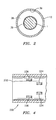
- membrane 230 for a cannula assembly in accordance with further embodiments is shown.
- membrane 230 includes an inner wall 232.
- Inner wall 232 includes a plurality of ridges 234, 236.
- membrane 230 compresses to form a gas-tight seal about the body of the surgical instrument.
- ridges 234, 236 will substantially fill any gaps that occur between inner wall 232 and the body of the surgical instrument.
- ridges 234, 236 and the outer surface of the body of the surgical instrument form the pressure barrier for inhibiting leakage of insufflation gases.
- the ridged structure shown in FIG. 3 is easily adapted to all the embodiments of the subject disclosure.
- sealing membrane 30 and/or membrane 122 discussed previously could be manufactured with ridges to improve the sealing characteristics.
- ridges 234, 236 are preferably longitudinally oriented along the sealing membrane's inner wall 232, it is within the scope of this disclosure to dispose ridges 234, 236 laterally or at some other orientation along inner wall 232 of sealing membrane 230.
- FIGS. 1-4 may include or omit the throughholes at the distal end of the assembly. Fluids such as insufflation gas or liquids may be introduced through a passage at the proximal end of the assembly to inflate the membrane.
- body 12 is illustrated as having a single throughhole 42, multiple throughholes 42 may be provided as exhibited in the embodiment of FIG. 3 .
- throughholes 42 may be positioned at any location along central body portion 22 positioned within the insufflated body cavity.
- the cannula may also have a variety of different shapes other than cylindrical, e.g., square, oval, rectangular, etc.
- Inflatable membrane can be fastened to the cannula using any known technique including those not disclosed herein.
Landscapes
- Health & Medical Sciences (AREA)
- Surgery (AREA)
- Life Sciences & Earth Sciences (AREA)
- Medical Informatics (AREA)
- Nuclear Medicine, Radiotherapy & Molecular Imaging (AREA)
- Engineering & Computer Science (AREA)
- Biomedical Technology (AREA)
- Heart & Thoracic Surgery (AREA)
- Pathology (AREA)
- Molecular Biology (AREA)
- Animal Behavior & Ethology (AREA)
- General Health & Medical Sciences (AREA)
- Public Health (AREA)
- Veterinary Medicine (AREA)
- Surgical Instruments (AREA)
- Materials For Medical Uses (AREA)
Claims (14)
- Kanülenanordnung (10, 100) zum Durchführen eines chirurgischen Eingriffs, welche umfasst:eine Kanüle (12, 104, 106), die eine Längsachse (a) definiert und einen Durchgang (29, 122) aufweist, der sich dort durch erstreckt; undeine längliche Membran (30, 124, 230), die in dem länglichen Durchgang (29, 122) der Kanüle (12, 100) angeordnet ist, wobei die längliche Membran (30, 124, 230) an jeweiligen Enden (32, 34) der länglichen Membran (30, 124, 230) an der Kanüle (12, 104, 106) befestigt ist, um einen ringförmigen Raum (38, 140) zwischen der länglichen Membran (30, 124, 230) und der Kanüle (12, 104, 106) zu definieren, wobei die Kanüle (12, 104, 106) ein Durchloch (42, 142) in Verbindung mit dem ringförmigen Raum (38, 140) aufweist, wodurch, wenn die Kanüle (10, 100) in einem insufflierten Körperhohlraum positioniert ist, Insufflationsgase oder - flüssigkeiten durch das Durchloch (42, 142) treten können, um den ringförmigen Raum (38, 140) auszudehnen und dadurch die längliche Membran (33, 124) zu veranlassen, eine Abdichtung um einen dort durch eingeführten Gegenstand zu bilden; und gekennzeichnet durch:eine zweite Abdichtung (44), die geeignet ist, um den longitudinalen Durchgang (29, 122) in der Kanüle in Abwesenheit eines durch den Durchgang (29, 122) aufgenommen Gegenstands abzudichten.
- Kanülenanordnung (10, 100) nach Anspruch 1, wobei die längliche Membran (30, 124, 230) ein Material umfasst, das aus der Gruppe ausgewählt ist, die aus KEVLAR und Nylon besteht.
- Kanülenanordnung (10, 100) nach Anspruch 2, wobei die längliche Membran (30, 124, 230) ein elastomerisches Material umfasst.
- Kanülenanordnung (10, 100) nach einem der vorangehenden Ansprüche, wobei die längliche Membran (30, 124, 230) einen Maschenaufbau umfasst, der sich bei Einführung eines dort durch eingesetzten Instruments ausdehnt.
- Kanülenanordnung (10, 100) nach einem der vorangehenden Ansprüche, wobei die längliche Membran (30, 124, 230) mindestens eine Rippe (234, 236) auf einem inneren Oberflächenabschnitt davon aufweist.
- Kanülenanordnung (10, 100) nach Anspruch 5, wobei die mindestens eine Rippe (234, 236) auf der länglichen Membran (30, 124, 230) so angeordnet ist, dass sie einen Leerraum zwischen dem inneren Oberflächenabschnitt der länglichen Membran (30, 124, 230) und dem Gegenstand besetzt, um das abdichtende Verhältnis mit dem Gegenstand zu fördern.
- Kanülenanordnung (10, 100) nach Anspruch 6, wobei die längliche Membran (30, 124, 230) eine Vielzahl von Rippen umfasst, die radial um den inneren Oberflächenabschnitt der länglichen Membran (30, 124, 230) herum beabstandet sind.
- Kanülenanordnung (10, 100) nach einem der vorangehenden Ansprüche, wobei die längliche Membran (30, 124, 230) geeignet ist, um den Durchgang (29, 122) als Reaktion auf das Einführen von Gasen in den ringförmigen Raum (38) und in Abwesenheit eines dort durch eingesetzten Gegenstands im Wesentlichen zu verschließen.
- Kanülenanordnung (10, 100) nach einem der vorangehenden Ansprüche, wobei das Durchloch (42, 142) an einem distalen Ende der Kanüle (12, 104, 106) in einem äußeren Wandabschnitt davon angeordnet ist.
- Kanülenanordnung (10, 100) nach einem der vorangehenden Ansprüche, umfassend einen zweiten Durchgang (136) neben einem proximalen Ende der Kanüle (104, 106) und in Verbindung mit dem ringförmigen Raum (140), um dem ringförmigen Raum Fluid bereitzustellen.
- Kanülenanordnung (10, 100) nach Anspruch 10, wobei der zweite Durchgang (136) zur Bereitstellung von Fluid für eine Fluidverbindung mit einer externen Quelle von Insufflationsgasen geeignet ist.
- Kanülenanordnung (10, 100) nach Anspruch 11, wobei die Kanüle ein Gehäuse (102) umfasst und ein Kanülenkörper (104, 106) sich aus dem Gehäuse (102) erstreckt, wobei der zweite Durchgang (136) zum Bereitstellen von Fluid einen Kanal (130) im Gehäuse (102) und in Verbindung mit dem ringförmigen Raum (140) umfasst, um den Durchtritt von Insufflationsgasen dort durch zu erlauben.
- Kanülenanordnung (10, 100) nach Anspruch 12, wobei ein Ende der länglichen Membran (124, 230) im Gehäuse (102) befestigt ist und das andere Ende der länglichen Membran (124, 230) im Kanülenkörper (104, 106) befestigt ist.
- Kanülenanordnung (10) nach einem der Ansprüche 1-11, wobei die Kanüle einen Kanülenkörper umfasst und jedes Ende der länglichen Membran (30) im Kanülenkörper (12) befestigt ist.
Priority Applications (3)
| Application Number | Priority Date | Filing Date | Title |
|---|---|---|---|
| EP10184312A EP2305147A3 (de) | 2002-11-08 | 2003-11-07 | Selbstverschliessende Kanüle |
| EP10151911A EP2174605B1 (de) | 2002-11-08 | 2003-11-07 | Selbstversiegelnde Kanüle |
| EP09150425A EP2042115B1 (de) | 2002-11-08 | 2003-11-07 | Selbstverschliessende Kanüle |
Applications Claiming Priority (3)
| Application Number | Priority Date | Filing Date | Title |
|---|---|---|---|
| US42506202P | 2002-11-08 | 2002-11-08 | |
| US425062P | 2002-11-08 | ||
| PCT/US2003/035586 WO2004043275A1 (en) | 2002-11-08 | 2003-11-07 | Self sealing cannula |
Related Child Applications (1)
| Application Number | Title | Priority Date | Filing Date |
|---|---|---|---|
| EP09150425A Division EP2042115B1 (de) | 2002-11-08 | 2003-11-07 | Selbstverschliessende Kanüle |
Publications (2)
| Publication Number | Publication Date |
|---|---|
| EP1558154A1 EP1558154A1 (de) | 2005-08-03 |
| EP1558154B1 true EP1558154B1 (de) | 2009-01-14 |
Family
ID=32312924
Family Applications (4)
| Application Number | Title | Priority Date | Filing Date |
|---|---|---|---|
| EP03779487A Expired - Lifetime EP1558154B1 (de) | 2002-11-08 | 2003-11-07 | Selbstverschliessende kanüle |
| EP10184312A Withdrawn EP2305147A3 (de) | 2002-11-08 | 2003-11-07 | Selbstverschliessende Kanüle |
| EP10151911A Expired - Lifetime EP2174605B1 (de) | 2002-11-08 | 2003-11-07 | Selbstversiegelnde Kanüle |
| EP09150425A Expired - Lifetime EP2042115B1 (de) | 2002-11-08 | 2003-11-07 | Selbstverschliessende Kanüle |
Family Applications After (3)
| Application Number | Title | Priority Date | Filing Date |
|---|---|---|---|
| EP10184312A Withdrawn EP2305147A3 (de) | 2002-11-08 | 2003-11-07 | Selbstverschliessende Kanüle |
| EP10151911A Expired - Lifetime EP2174605B1 (de) | 2002-11-08 | 2003-11-07 | Selbstversiegelnde Kanüle |
| EP09150425A Expired - Lifetime EP2042115B1 (de) | 2002-11-08 | 2003-11-07 | Selbstverschliessende Kanüle |
Country Status (8)
| Country | Link |
|---|---|
| US (2) | US7563250B2 (de) |
| EP (4) | EP1558154B1 (de) |
| JP (3) | JP4777655B2 (de) |
| AU (2) | AU2003285163B2 (de) |
| CA (1) | CA2504540C (de) |
| DE (2) | DE60325879D1 (de) |
| ES (3) | ES2388649T3 (de) |
| WO (1) | WO2004043275A1 (de) |
Families Citing this family (110)
| Publication number | Priority date | Publication date | Assignee | Title |
|---|---|---|---|---|
| EP2428172B1 (de) | 2001-09-24 | 2013-07-24 | Applied Medical Resources Corporation | Obturator ohne Klinge |
| EP1503677B1 (de) | 2002-05-16 | 2011-05-04 | Applied Medical Resources Corporation | Obturator mit kegelspitze |
| EP1558154B1 (de) | 2002-11-08 | 2009-01-14 | Tyco Healthcare Group Lp | Selbstverschliessende kanüle |
| US7854724B2 (en) | 2003-04-08 | 2010-12-21 | Surgiquest, Inc. | Trocar assembly with pneumatic sealing |
| US7182752B2 (en) * | 2003-04-08 | 2007-02-27 | Surgiquest, Incorporated | Continuous gas flow trocar assembly |
| US20050059934A1 (en) | 2003-04-25 | 2005-03-17 | Thomas Wenchell | Surgical access apparatus |
| EP2545865B1 (de) | 2003-10-03 | 2015-07-08 | Applied Medical Resources Corporation | Optischer Obturator ohne Klinge |
| EP3175804B1 (de) | 2004-06-29 | 2018-09-26 | Applied Medical Resources Corporation | Insufflierendes optisches operationsinstrument |
| US8241251B2 (en) | 2004-08-25 | 2012-08-14 | Tyco Healthcare Group Lp | Gel seal for a surgical trocar apparatus |
| US8460178B2 (en) * | 2004-11-30 | 2013-06-11 | Atul Kumar | Method and system for minimizing leakage of a distending medium during endoscopic procedures |
| WO2006113800A2 (en) * | 2005-04-20 | 2006-10-26 | Stout Medical Group, Llc | Self-sealing surgical access port |
| US7575565B2 (en) * | 2005-08-19 | 2009-08-18 | Cannuflow, Inc. | Extravasation minimization device |
| DE602006016841D1 (de) * | 2005-10-14 | 2010-10-21 | Applied Med Resources | Chirurgische vorrichtungen, systeme und verfahren dafür mit gelmaterialien, gelbeschichtungen bzw. gelschmiermitteln |
| DE102006015690A1 (de) | 2006-03-27 | 2007-10-11 | Aesculap Ag & Co. Kg | Chirurgisches Dichtelement, chirurgische Dichtung und chirurgisches Abdichtungssystem |
| US8579807B2 (en) | 2008-04-28 | 2013-11-12 | Ethicon Endo-Surgery, Inc. | Absorbing fluids in a surgical access device |
| US8690831B2 (en) | 2008-04-25 | 2014-04-08 | Ethicon Endo-Surgery, Inc. | Gas jet fluid removal in a trocar |
| US9155557B2 (en) * | 2007-04-17 | 2015-10-13 | Surgiquest, Inc. | Endoluminal and transluminal surgical methods and devices |
| AU2007303069B2 (en) | 2006-10-06 | 2013-03-21 | Applied Medical Resources Corporation | Visual insufflation port |
| US7819842B2 (en) * | 2006-11-21 | 2010-10-26 | Medtronic, Inc. | Chronically implantable guide tube for repeated intermittent delivery of materials or fluids to targeted tissue sites |
| US8100929B2 (en) | 2007-06-29 | 2012-01-24 | Ethicon Endo-Surgery, Inc. | Duckbill seal with fluid drainage feature |
| US8357123B2 (en) | 2007-09-17 | 2013-01-22 | Covidien Lp | Surgical portal with gel and fabric seal assembly |
| WO2009046164A1 (en) | 2007-10-05 | 2009-04-09 | Tyco Healthcare Group Lp | Seal anchor for use in surgical procedures |
| US8118784B2 (en) * | 2007-10-30 | 2012-02-21 | Cook Medical Technologies Llc | Haemostatic valve |
| US7976501B2 (en) | 2007-12-07 | 2011-07-12 | Ethicon Endo-Surgery, Inc. | Trocar seal with reduced contact area |
| WO2009086505A2 (en) * | 2007-12-27 | 2009-07-09 | University Of South Florida | Multichannel trocar |
| EP2837345B1 (de) | 2008-01-25 | 2016-10-05 | Applied Medical Resources Corporation | Insufflierendes Zugangssystem |
| US11235111B2 (en) | 2008-04-28 | 2022-02-01 | Ethicon Llc | Surgical access device |
| USD700326S1 (en) | 2008-04-28 | 2014-02-25 | Ethicon Endo-Surgery, Inc. | Trocar housing |
| US8870747B2 (en) | 2008-04-28 | 2014-10-28 | Ethicon Endo-Surgery, Inc. | Scraping fluid removal in a surgical access device |
| US9358041B2 (en) | 2008-04-28 | 2016-06-07 | Ethicon Endo-Surgery, Llc | Wicking fluid management in a surgical access device |
| US8636686B2 (en) | 2008-04-28 | 2014-01-28 | Ethicon Endo-Surgery, Inc. | Surgical access device |
| US8568362B2 (en) | 2008-04-28 | 2013-10-29 | Ethicon Endo-Surgery, Inc. | Surgical access device with sorbents |
| US8273060B2 (en) | 2008-04-28 | 2012-09-25 | Ethicon Endo-Surgery, Inc. | Fluid removal in a surgical access device |
| US7981092B2 (en) | 2008-05-08 | 2011-07-19 | Ethicon Endo-Surgery, Inc. | Vibratory trocar |
| US8012129B2 (en) * | 2008-06-25 | 2011-09-06 | Tyco Healthcare Group Lp | Surgical portal apparatus with waffle seal |
| DE102008033375A1 (de) | 2008-07-09 | 2010-01-14 | Aesculap Ag | Chirurgische Dichtelementhalterung zum Halten eines chirurgischen Dichtelements und chirurgisches Abdichtungssystem |
| DE102008033374A1 (de) * | 2008-07-09 | 2010-01-14 | Aesculap Ag | Chirurgisches Schutzvorrichtung für ein chirurgisches Dichtelement und chirurgisches Abdichtungssystem |
| ES2917876T3 (es) | 2008-09-29 | 2022-07-12 | Applied Med Resources | Sistema de trócar de primera entrada |
| USD738500S1 (en) | 2008-10-02 | 2015-09-08 | Covidien Lp | Seal anchor for use in surgical procedures |
| KR20110079885A (ko) | 2008-10-10 | 2011-07-11 | 서지퀘스트, 인코포레이티드 | 외과용 접근 장치 |
| EP2341849B1 (de) | 2008-10-10 | 2019-12-18 | SurgiQuest, Incorporated | System für verbesserte gasrückführung in chirurgischen trokaren mit pneumatischer versiegelung |
| US8740925B2 (en) | 2008-10-10 | 2014-06-03 | Covidien Lp | Trocar assembly |
| US8147405B2 (en) * | 2008-10-30 | 2012-04-03 | Ethicon Endo-Surgery, Inc. | Surgical access port with multilayered tortuous path seal |
| US8317690B2 (en) | 2009-03-31 | 2012-11-27 | Covidien Lp | Foam port and introducer assembly |
| US8323184B2 (en) | 2009-03-31 | 2012-12-04 | Covidien Lp | Surgical access port and associated introducer mechanism |
| US20100268162A1 (en) * | 2009-04-15 | 2010-10-21 | Ethicon Endo-Surgery, Inc. | Cannula with sealing elements |
| US8206358B2 (en) * | 2009-05-06 | 2012-06-26 | Tyco Healthcare Group Lp | Ring and seal for trocar |
| US9138207B2 (en) | 2009-05-19 | 2015-09-22 | Teleflex Medical Incorporated | Methods and devices for laparoscopic surgery |
| US8177755B2 (en) * | 2009-05-21 | 2012-05-15 | Tyco Healthcare Group Lp | Access sheath with central seal |
| US8257252B2 (en) | 2009-08-06 | 2012-09-04 | Tyco Healthcare Group Lp | Elongated seal anchor for use in surgical procedures |
| US9199034B2 (en) * | 2009-11-09 | 2015-12-01 | Becton, Dickinson And Company | Drug delivery devices, systems, and methods |
| US20110124968A1 (en) * | 2009-11-24 | 2011-05-26 | Tyco Healthcare Group Lp | Surgical portal and introducer assembly |
| US8764647B2 (en) * | 2009-11-24 | 2014-07-01 | Covidien Lp | Foam port device having closed-end lumens |
| EP2525720A1 (de) | 2010-01-20 | 2012-11-28 | EON Surgical Ltd. | System für den einsatz eines länglichen elements in einer körperhöhle |
| US8721539B2 (en) | 2010-01-20 | 2014-05-13 | EON Surgical Ltd. | Rapid laparoscopy exchange system and method of use thereof |
| US20110196407A1 (en) * | 2010-02-05 | 2011-08-11 | Benmaamer Moutaa | Multiple function surgical instrument |
| CN103220987B (zh) | 2010-09-19 | 2016-05-18 | 意昂外科有限公司 | 微型腹腔镜及其改进 |
| US8864659B2 (en) | 2010-11-23 | 2014-10-21 | Covidien Lp | Seal anchor for use in surgical procedures |
| US20120157782A1 (en) | 2010-12-20 | 2012-06-21 | Francesco Alfieri | Hand access device |
| US8550992B2 (en) | 2010-12-20 | 2013-10-08 | Covidien Lp | Two-part access assembly |
| US8602983B2 (en) | 2010-12-20 | 2013-12-10 | Covidien Lp | Access assembly having undercut structure |
| US8641610B2 (en) | 2010-12-20 | 2014-02-04 | Covidien Lp | Access assembly with translating lumens |
| US8696557B2 (en) | 2010-12-21 | 2014-04-15 | Covidien Lp | Access assembly including inflatable seal member |
| US8753267B2 (en) | 2011-01-24 | 2014-06-17 | Covidien Lp | Access assembly insertion device |
| WO2012122263A2 (en) | 2011-03-08 | 2012-09-13 | Surgiquest, Inc. | Trocar assembly with pneumatic sealing |
| US9119666B2 (en) * | 2011-03-25 | 2015-09-01 | Covidien Lp | Access port with integrated flexible sleeve |
| US9254148B2 (en) | 2011-05-02 | 2016-02-09 | Applied Medical Resources Corporation | Low-profile surgical universal access port |
| CN103619399B (zh) * | 2011-07-04 | 2016-01-20 | 泰尔茂株式会社 | 插管器用鞘 |
| US20130190573A1 (en) * | 2012-01-19 | 2013-07-25 | Covidien Lp | Wound protector including flexible and rigid liners |
| EP3488894B1 (de) | 2012-02-15 | 2023-04-05 | Intuitive Surgical Operations, Inc. | Reibungsarme kanülendichtungen für minimalinvasive robotergestützte chirurgie |
| US9271639B2 (en) | 2012-02-29 | 2016-03-01 | Covidien Lp | Surgical introducer and access port assembly |
| US9572626B2 (en) | 2013-02-15 | 2017-02-21 | Intuitive Surgical Operations, Inc. | Actuated cannula seal |
| US11129964B2 (en) * | 2013-03-13 | 2021-09-28 | The Board Of Regents Of The University Of Texas System | Trapping sheaths and guide catheters |
| EP2999419B1 (de) | 2013-05-22 | 2020-12-23 | Covidien LP | Vorrichtung zur steuerung von chirurgischen instrumenten unter verwendung einer portanordnung |
| EP3134210A4 (de) * | 2014-04-25 | 2017-06-28 | Siemens Healthcare Diagnostics Inc. | Probensammeleinheit |
| US10064649B2 (en) | 2014-07-07 | 2018-09-04 | Covidien Lp | Pleated seal for surgical hand or instrument access |
| US9707011B2 (en) | 2014-11-12 | 2017-07-18 | Covidien Lp | Attachments for use with a surgical access device |
| US10893899B2 (en) | 2016-03-26 | 2021-01-19 | Paul Weber | Apparatus and systems for minimally invasive dissection of tissues |
| US10603101B2 (en) | 2016-03-26 | 2020-03-31 | Paul Joseph Weber | Apparatus, systems and methods for minimally invasive dissection of tissues |
| US11510730B2 (en) | 2016-03-26 | 2022-11-29 | Paul Joseph Weber | Apparatus and methods for minimally invasive dissection and modification of tissues |
| US10874426B2 (en) | 2017-02-10 | 2020-12-29 | Covidien Lp | Seal assembly with integral filter and evacuation port |
| US11160682B2 (en) | 2017-06-19 | 2021-11-02 | Covidien Lp | Method and apparatus for accessing matter disposed within an internal body vessel |
| US10828065B2 (en) | 2017-08-28 | 2020-11-10 | Covidien Lp | Surgical access system |
| US10675056B2 (en) | 2017-09-07 | 2020-06-09 | Covidien Lp | Access apparatus with integrated fluid connector and control valve |
| US10709475B2 (en) | 2018-03-07 | 2020-07-14 | Edward J. Mikol | Pumping surgical cannula |
| US11389193B2 (en) | 2018-10-02 | 2022-07-19 | Covidien Lp | Surgical access device with fascial closure system |
| US11457949B2 (en) | 2018-10-12 | 2022-10-04 | Covidien Lp | Surgical access device and seal guard for use therewith |
| US11166748B2 (en) | 2019-02-11 | 2021-11-09 | Covidien Lp | Seal assemblies for surgical access assemblies |
| US10792071B2 (en) | 2019-02-11 | 2020-10-06 | Covidien Lp | Seals for surgical access assemblies |
| US11000313B2 (en) | 2019-04-25 | 2021-05-11 | Covidien Lp | Seals for surgical access devices |
| US11413068B2 (en) | 2019-05-09 | 2022-08-16 | Covidien Lp | Seal assemblies for surgical access assemblies |
| US11259840B2 (en) | 2019-06-21 | 2022-03-01 | Covidien Lp | Valve assemblies for surgical access assemblies |
| US11259841B2 (en) | 2019-06-21 | 2022-03-01 | Covidien Lp | Seal assemblies for surgical access assemblies |
| US11357542B2 (en) | 2019-06-21 | 2022-06-14 | Covidien Lp | Valve assembly and retainer for surgical access assembly |
| US11413065B2 (en) | 2019-06-28 | 2022-08-16 | Covidien Lp | Seal assemblies for surgical access assemblies |
| US11399865B2 (en) | 2019-08-02 | 2022-08-02 | Covidien Lp | Seal assemblies for surgical access assemblies |
| US11523842B2 (en) | 2019-09-09 | 2022-12-13 | Covidien Lp | Reusable surgical port with disposable seal assembly |
| US11432843B2 (en) | 2019-09-09 | 2022-09-06 | Covidien Lp | Centering mechanisms for a surgical access assembly |
| US20250318852A1 (en) * | 2019-09-12 | 2025-10-16 | Edward J. Mikol | Simplified surgical cannula |
| US11812991B2 (en) | 2019-10-18 | 2023-11-14 | Covidien Lp | Seal assemblies for surgical access assemblies |
| US11464540B2 (en) | 2020-01-17 | 2022-10-11 | Covidien Lp | Surgical access device with fixation mechanism |
| US12324606B2 (en) | 2020-01-28 | 2025-06-10 | Covidien Lp | Seal assemblies for surgical access assemblies |
| US11576701B2 (en) | 2020-03-05 | 2023-02-14 | Covidien Lp | Surgical access assembly having a pump |
| US11446058B2 (en) | 2020-03-27 | 2022-09-20 | Covidien Lp | Fixture device for folding a seal member |
| US11717321B2 (en) | 2020-04-24 | 2023-08-08 | Covidien Lp | Access assembly with retention mechanism |
| US11529170B2 (en) | 2020-04-29 | 2022-12-20 | Covidien Lp | Expandable surgical access port |
| US11622790B2 (en) | 2020-05-21 | 2023-04-11 | Covidien Lp | Obturators for surgical access assemblies and methods of assembly thereof |
| US11751908B2 (en) | 2020-06-19 | 2023-09-12 | Covidien Lp | Seal assembly for surgical access assemblies |
| CN113974775B (zh) * | 2021-11-17 | 2023-05-16 | 上海腾复医疗科技有限公司 | 鞘管密封装置及包含其的血栓抽吸系统 |
| WO2025184370A1 (en) | 2024-02-27 | 2025-09-04 | Mikol Edward J | Cannula with impeller pump, peristaltic pump and other pumps |
Family Cites Families (43)
| Publication number | Priority date | Publication date | Assignee | Title |
|---|---|---|---|---|
| FR2182730B1 (de) | 1972-05-05 | 1974-09-27 | Rhone Poulenc Sa | |
| US5308336A (en) | 1982-09-28 | 1994-05-03 | Applied Medical Resources | Seal protection mechanism |
| US4655752A (en) | 1983-10-24 | 1987-04-07 | Acufex Microsurgical, Inc. | Surgical cannula |
| US4637396A (en) * | 1984-10-26 | 1987-01-20 | Cook, Incorporated | Balloon catheter |
| US4909798A (en) | 1987-11-12 | 1990-03-20 | Daig Corporation | Universal hemostasis cannula |
| DE8904025U1 (de) | 1988-04-07 | 1989-05-24 | Schneider (Europe) AG, Zürich | Einführungsschleuse in einem Schlauchverbindungsstück für eine Katheteranordnung |
| CA1329091C (en) * | 1989-01-31 | 1994-05-03 | Geoffrey S. Martin | Catheter with balloon retainer |
| US5514153A (en) * | 1990-03-02 | 1996-05-07 | General Surgical Innovations, Inc. | Method of dissecting tissue layers |
| US5071411A (en) * | 1990-03-26 | 1991-12-10 | Cordis Corporation | Pressure-actuated valve for sealing flow conduit |
| US5385553A (en) | 1991-07-18 | 1995-01-31 | Applied Medical Resources Corporation | Trocar with floating septum seal |
| US5273545A (en) * | 1991-10-15 | 1993-12-28 | Apple Medical Corporation | Endoscopic cannula with tricuspid leaf valve |
| US5209736A (en) | 1991-10-18 | 1993-05-11 | Ethicon, Inc. | Trocar method and apparatus |
| US5545142A (en) | 1991-10-18 | 1996-08-13 | Ethicon, Inc. | Seal members for surgical trocars |
| US5197955A (en) | 1991-10-18 | 1993-03-30 | Ethicon, Inc. | Universal seal for trocar assembly |
| US5242412A (en) | 1992-01-21 | 1993-09-07 | Blake Joseph W Iii | Trocar tube subassembly having sealing ring and duckbill sealing tube having planar, truncate, diverging sealing bills |
| US5201714A (en) | 1992-03-05 | 1993-04-13 | Conmed Corporation | Laparoscopic cannula |
| JPH0611056A (ja) * | 1992-06-24 | 1994-01-21 | Tsukishima Kikai Co Ltd | 流路分配装置、疑似移動床および連続吸着法 |
| US5496280A (en) | 1992-07-02 | 1996-03-05 | Applied Medical Resources Corporation | Trocar valve assembly |
| DE4231414C2 (de) | 1992-09-19 | 1996-08-29 | Ploucquet C F Gmbh | Abdeckung aus Kunststoff für eine Kompostmiete |
| US5476475A (en) | 1992-11-23 | 1995-12-19 | Applied Medical Resources | Trocar with universal seal protector |
| US5407433A (en) | 1993-02-10 | 1995-04-18 | Origin Medsystems, Inc. | Gas-tight seal accommodating surgical instruments with a wide range of diameters |
| US5411483A (en) | 1993-02-10 | 1995-05-02 | Origin Medsystems, Inc. | Gas-tight seal accommodating surgical instruments with a wide range of diameters |
| US5380288A (en) | 1993-03-30 | 1995-01-10 | Innovasive Devices, Inc. | Surgical cannula and trocar system and method of using the same |
| US5366478A (en) * | 1993-07-27 | 1994-11-22 | Ethicon, Inc. | Endoscopic surgical sealing device |
| US5643911A (en) | 1994-05-19 | 1997-07-01 | Mitsubishi Chemical Corporation | Medicament for therapeutic and prophylactic treatment of diseases caused by smooth muscle cell hyperplasia |
| AU4763296A (en) | 1995-02-03 | 1996-08-21 | Inbae Yoon | Cannula with distal end valve |
| US5634911A (en) * | 1995-05-19 | 1997-06-03 | General Surgical Innovations, Inc. | Screw-type skin seal with inflatable membrane |
| US5997515A (en) * | 1995-05-19 | 1999-12-07 | General Surgical Innovations, Inc. | Screw-type skin seal with inflatable membrane |
| US5584850A (en) | 1995-05-25 | 1996-12-17 | Applied Medical Resources Corporation | Trocar having an anti-inversion seal |
| US5545179A (en) | 1995-07-21 | 1996-08-13 | Ethicon Endo-Surgery, Inc. | Endoscopic access assembly |
| US5814026A (en) | 1996-03-19 | 1998-09-29 | Yoon; Inbae | Endoscopic portal having a universal seal and methods for introducing instruments therethrough |
| US5820606A (en) | 1996-06-11 | 1998-10-13 | Origin Medsystems, Inc. | Reusable cannula with disposable seal |
| US5993471A (en) | 1996-10-22 | 1999-11-30 | Erol D. Riza | Trocar assembly |
| US6276661B1 (en) * | 1996-11-06 | 2001-08-21 | Medtronic, Inc. | Pressure actuated introducer valve |
| US5792113A (en) | 1996-12-12 | 1998-08-11 | Ethicon Endo-Surgerym Inc. | Universal seal for a trocar |
| US5727770A (en) * | 1997-02-07 | 1998-03-17 | Core Dynamics, Inc. | Double valve cannula seal |
| US5906595A (en) | 1997-04-25 | 1999-05-25 | Ethicon Endo-Surgery, Inc. | Trocar having protector with flexible end and improved seal assembly |
| US6197002B1 (en) | 1997-12-10 | 2001-03-06 | Phillips Plastics Corporation | Laparoscopic tool and method |
| US6004303A (en) * | 1997-12-10 | 1999-12-21 | Phillips Plastics Corporation | Choker catheter |
| US6258065B1 (en) | 1999-03-26 | 2001-07-10 | Core Dynamics, Inc. | Surgical instrument seal assembly |
| US6447489B1 (en) * | 2000-01-18 | 2002-09-10 | Ethicon Endo-Surgey, Inc. | Laparoscopic access tool with gas seal |
| JP4365045B2 (ja) * | 2001-01-15 | 2009-11-18 | 株式会社トップ | 医療用具の弁構造及び弁構造が組込まれたカニューレ |
| EP1558154B1 (de) | 2002-11-08 | 2009-01-14 | Tyco Healthcare Group Lp | Selbstverschliessende kanüle |
-
2003
- 2003-11-07 EP EP03779487A patent/EP1558154B1/de not_active Expired - Lifetime
- 2003-11-07 ES ES10151911T patent/ES2388649T3/es not_active Expired - Lifetime
- 2003-11-07 WO PCT/US2003/035586 patent/WO2004043275A1/en not_active Ceased
- 2003-11-07 ES ES03779487T patent/ES2319761T3/es not_active Expired - Lifetime
- 2003-11-07 DE DE60325879T patent/DE60325879D1/de not_active Expired - Lifetime
- 2003-11-07 AU AU2003285163A patent/AU2003285163B2/en not_active Ceased
- 2003-11-07 CA CA2504540A patent/CA2504540C/en not_active Expired - Fee Related
- 2003-11-07 JP JP2004551893A patent/JP4777655B2/ja not_active Expired - Fee Related
- 2003-11-07 EP EP10184312A patent/EP2305147A3/de not_active Withdrawn
- 2003-11-07 DE DE60336093T patent/DE60336093D1/de not_active Expired - Lifetime
- 2003-11-07 EP EP10151911A patent/EP2174605B1/de not_active Expired - Lifetime
- 2003-11-07 ES ES09150425T patent/ES2360755T3/es not_active Expired - Lifetime
- 2003-11-07 EP EP09150425A patent/EP2042115B1/de not_active Expired - Lifetime
- 2003-11-07 US US10/704,053 patent/US7563250B2/en not_active Expired - Fee Related
-
2009
- 2009-02-13 AU AU2009200579A patent/AU2009200579B2/en not_active Ceased
- 2009-07-15 US US12/503,419 patent/US20090275898A1/en not_active Abandoned
- 2009-11-17 JP JP2009262392A patent/JP2010075716A/ja active Pending
- 2009-11-17 JP JP2009262391A patent/JP2010063905A/ja active Pending
Also Published As
| Publication number | Publication date |
|---|---|
| JP2010063905A (ja) | 2010-03-25 |
| AU2003285163A1 (en) | 2004-06-03 |
| EP2305147A2 (de) | 2011-04-06 |
| EP2305147A3 (de) | 2011-10-19 |
| EP2042115A1 (de) | 2009-04-01 |
| DE60325879D1 (de) | 2009-03-05 |
| EP2174605B1 (de) | 2012-07-11 |
| WO2004043275A1 (en) | 2004-05-27 |
| EP2174605A3 (de) | 2010-04-21 |
| ES2388649T3 (es) | 2012-10-17 |
| ES2360755T3 (es) | 2011-06-08 |
| EP2174605A2 (de) | 2010-04-14 |
| ES2319761T3 (es) | 2009-05-12 |
| DE60336093D1 (de) | 2011-03-31 |
| CA2504540C (en) | 2012-01-24 |
| US20090275898A1 (en) | 2009-11-05 |
| AU2009200579A1 (en) | 2009-03-05 |
| EP1558154A1 (de) | 2005-08-03 |
| US20040162531A1 (en) | 2004-08-19 |
| JP2010075716A (ja) | 2010-04-08 |
| AU2009200579B2 (en) | 2011-03-03 |
| JP2006505357A (ja) | 2006-02-16 |
| AU2003285163B2 (en) | 2008-11-13 |
| CA2504540A1 (en) | 2004-05-27 |
| US7563250B2 (en) | 2009-07-21 |
| EP2042115B1 (de) | 2011-02-16 |
| JP4777655B2 (ja) | 2011-09-21 |
Similar Documents
| Publication | Publication Date | Title |
|---|---|---|
| EP2042115B1 (de) | Selbstverschliessende Kanüle | |
| USRE44790E1 (en) | Skin seal | |
| US5871474A (en) | Screw-type skin seal with inflatable membrane | |
| US6916331B2 (en) | Skin seal with inflatable membrane | |
| US20100036323A1 (en) | Flexible cannula with seal | |
| AU2008219112B2 (en) | Flexible external cannula sheath | |
| WO2007140449A2 (en) | Bifurcated endoscopy cannula | |
| EP4026504B1 (de) | Kanülenanordnung mit einer saugnapfdichtung | |
| US20110082340A1 (en) | Foam collar for surgical access devices |
Legal Events
| Date | Code | Title | Description |
|---|---|---|---|
| PUAI | Public reference made under article 153(3) epc to a published international application that has entered the european phase |
Free format text: ORIGINAL CODE: 0009012 |
|
| 17P | Request for examination filed |
Effective date: 20050520 |
|
| AK | Designated contracting states |
Kind code of ref document: A1 Designated state(s): AT BE BG CH CY CZ DE DK EE ES FI FR GB GR HU IE IT LI LU MC NL PT RO SE SI SK TR |
|
| AX | Request for extension of the european patent |
Extension state: AL LT LV MK |
|
| DAX | Request for extension of the european patent (deleted) | ||
| RBV | Designated contracting states (corrected) |
Designated state(s): DE ES FR GB IE IT |
|
| 17Q | First examination report despatched |
Effective date: 20051227 |
|
| GRAP | Despatch of communication of intention to grant a patent |
Free format text: ORIGINAL CODE: EPIDOSNIGR1 |
|
| GRAS | Grant fee paid |
Free format text: ORIGINAL CODE: EPIDOSNIGR3 |
|
| GRAA | (expected) grant |
Free format text: ORIGINAL CODE: 0009210 |
|
| AK | Designated contracting states |
Kind code of ref document: B1 Designated state(s): DE ES FR GB IE IT |
|
| REG | Reference to a national code |
Ref country code: GB Ref legal event code: FG4D |
|
| REG | Reference to a national code |
Ref country code: IE Ref legal event code: FG4D |
|
| REF | Corresponds to: |
Ref document number: 60325879 Country of ref document: DE Date of ref document: 20090305 Kind code of ref document: P |
|
| REG | Reference to a national code |
Ref country code: ES Ref legal event code: FG2A Ref document number: 2319761 Country of ref document: ES Kind code of ref document: T3 |
|
| PLBE | No opposition filed within time limit |
Free format text: ORIGINAL CODE: 0009261 |
|
| STAA | Information on the status of an ep patent application or granted ep patent |
Free format text: STATUS: NO OPPOSITION FILED WITHIN TIME LIMIT |
|
| 26N | No opposition filed |
Effective date: 20091015 |
|
| PGFP | Annual fee paid to national office [announced via postgrant information from national office to epo] |
Ref country code: ES Payment date: 20121126 Year of fee payment: 10 Ref country code: IT Payment date: 20121123 Year of fee payment: 10 |
|
| PG25 | Lapsed in a contracting state [announced via postgrant information from national office to epo] |
Ref country code: IT Free format text: LAPSE BECAUSE OF NON-PAYMENT OF DUE FEES Effective date: 20131107 |
|
| REG | Reference to a national code |
Ref country code: ES Ref legal event code: FD2A Effective date: 20150709 |
|
| PG25 | Lapsed in a contracting state [announced via postgrant information from national office to epo] |
Ref country code: ES Free format text: LAPSE BECAUSE OF NON-PAYMENT OF DUE FEES Effective date: 20131108 |
|
| REG | Reference to a national code |
Ref country code: FR Ref legal event code: PLFP Year of fee payment: 13 |
|
| REG | Reference to a national code |
Ref country code: FR Ref legal event code: PLFP Year of fee payment: 14 |
|
| PGFP | Annual fee paid to national office [announced via postgrant information from national office to epo] |
Ref country code: FR Payment date: 20161024 Year of fee payment: 14 Ref country code: GB Payment date: 20161027 Year of fee payment: 14 Ref country code: DE Payment date: 20161020 Year of fee payment: 14 Ref country code: IE Payment date: 20161024 Year of fee payment: 14 |
|
| REG | Reference to a national code |
Ref country code: DE Ref legal event code: R119 Ref document number: 60325879 Country of ref document: DE |
|
| GBPC | Gb: european patent ceased through non-payment of renewal fee |
Effective date: 20171107 |
|
| REG | Reference to a national code |
Ref country code: FR Ref legal event code: ST Effective date: 20180731 |
|
| REG | Reference to a national code |
Ref country code: IE Ref legal event code: MM4A |
|
| PG25 | Lapsed in a contracting state [announced via postgrant information from national office to epo] |
Ref country code: FR Free format text: LAPSE BECAUSE OF NON-PAYMENT OF DUE FEES Effective date: 20171130 Ref country code: IE Free format text: LAPSE BECAUSE OF NON-PAYMENT OF DUE FEES Effective date: 20171107 Ref country code: DE Free format text: LAPSE BECAUSE OF NON-PAYMENT OF DUE FEES Effective date: 20180602 |
|
| PG25 | Lapsed in a contracting state [announced via postgrant information from national office to epo] |
Ref country code: GB Free format text: LAPSE BECAUSE OF NON-PAYMENT OF DUE FEES Effective date: 20171107 |