EP1557704A2 - Kühlkörperelement für optische Baugruppe und Zusammenbauverfahren - Google Patents
Kühlkörperelement für optische Baugruppe und Zusammenbauverfahren Download PDFInfo
- Publication number
- EP1557704A2 EP1557704A2 EP05075047A EP05075047A EP1557704A2 EP 1557704 A2 EP1557704 A2 EP 1557704A2 EP 05075047 A EP05075047 A EP 05075047A EP 05075047 A EP05075047 A EP 05075047A EP 1557704 A2 EP1557704 A2 EP 1557704A2
- Authority
- EP
- European Patent Office
- Prior art keywords
- optical
- housing
- transceiver
- subassembly
- optical subassembly
- Prior art date
- Legal status (The legal status is an assumption and is not a legal conclusion. Google has not performed a legal analysis and makes no representation as to the accuracy of the status listed.)
- Granted
Links
- 230000003287 optical effect Effects 0.000 title claims abstract description 201
- 238000000034 method Methods 0.000 title claims description 8
- 230000008878 coupling Effects 0.000 claims description 10
- 238000010168 coupling process Methods 0.000 claims description 10
- 238000005859 coupling reaction Methods 0.000 claims description 10
- 239000004593 Epoxy Substances 0.000 claims description 8
- RYGMFSIKBFXOCR-UHFFFAOYSA-N Copper Chemical compound [Cu] RYGMFSIKBFXOCR-UHFFFAOYSA-N 0.000 claims description 3
- 229910052802 copper Inorganic materials 0.000 claims description 3
- 239000010949 copper Substances 0.000 claims description 3
- BQCADISMDOOEFD-UHFFFAOYSA-N Silver Chemical compound [Ag] BQCADISMDOOEFD-UHFFFAOYSA-N 0.000 claims description 2
- 229910052709 silver Inorganic materials 0.000 claims description 2
- 239000004332 silver Substances 0.000 claims description 2
- 238000005452 bending Methods 0.000 claims 1
- 239000000463 material Substances 0.000 description 8
- 230000008569 process Effects 0.000 description 4
- 229910000679 solder Inorganic materials 0.000 description 4
- 229910001220 stainless steel Inorganic materials 0.000 description 4
- 239000010935 stainless steel Substances 0.000 description 4
- 125000003700 epoxy group Chemical group 0.000 description 3
- 229920000647 polyepoxide Polymers 0.000 description 3
- HCHKCACWOHOZIP-UHFFFAOYSA-N Zinc Chemical compound [Zn] HCHKCACWOHOZIP-UHFFFAOYSA-N 0.000 description 2
- 230000000712 assembly Effects 0.000 description 2
- 238000000429 assembly Methods 0.000 description 2
- 238000006243 chemical reaction Methods 0.000 description 2
- 239000004020 conductor Substances 0.000 description 2
- 239000000835 fiber Substances 0.000 description 2
- 238000009434 installation Methods 0.000 description 2
- 230000001131 transforming effect Effects 0.000 description 2
- 239000011701 zinc Substances 0.000 description 2
- 229910052725 zinc Inorganic materials 0.000 description 2
- 230000006978 adaptation Effects 0.000 description 1
- 230000002457 bidirectional effect Effects 0.000 description 1
- 230000020169 heat generation Effects 0.000 description 1
- 230000006872 improvement Effects 0.000 description 1
- 239000013307 optical fiber Substances 0.000 description 1
- 230000005693 optoelectronics Effects 0.000 description 1
- 239000004065 semiconductor Substances 0.000 description 1
- 238000003466 welding Methods 0.000 description 1
Images


Classifications
-
- G—PHYSICS
- G02—OPTICS
- G02B—OPTICAL ELEMENTS, SYSTEMS OR APPARATUS
- G02B6/00—Light guides; Structural details of arrangements comprising light guides and other optical elements, e.g. couplings
- G02B6/24—Coupling light guides
- G02B6/42—Coupling light guides with opto-electronic elements
- G02B6/4201—Packages, e.g. shape, construction, internal or external details
-
- G—PHYSICS
- G02—OPTICS
- G02B—OPTICAL ELEMENTS, SYSTEMS OR APPARATUS
- G02B6/00—Light guides; Structural details of arrangements comprising light guides and other optical elements, e.g. couplings
- G02B6/24—Coupling light guides
- G02B6/42—Coupling light guides with opto-electronic elements
- G02B6/4201—Packages, e.g. shape, construction, internal or external details
- G02B6/4246—Bidirectionally operating package structures
-
- G—PHYSICS
- G02—OPTICS
- G02B—OPTICAL ELEMENTS, SYSTEMS OR APPARATUS
- G02B6/00—Light guides; Structural details of arrangements comprising light guides and other optical elements, e.g. couplings
- G02B6/24—Coupling light guides
- G02B6/42—Coupling light guides with opto-electronic elements
- G02B6/4201—Packages, e.g. shape, construction, internal or external details
- G02B6/4256—Details of housings
-
- G—PHYSICS
- G02—OPTICS
- G02B—OPTICAL ELEMENTS, SYSTEMS OR APPARATUS
- G02B6/00—Light guides; Structural details of arrangements comprising light guides and other optical elements, e.g. couplings
- G02B6/24—Coupling light guides
- G02B6/42—Coupling light guides with opto-electronic elements
- G02B6/4201—Packages, e.g. shape, construction, internal or external details
- G02B6/4266—Thermal aspects, temperature control or temperature monitoring
- G02B6/4268—Cooling
- G02B6/4269—Cooling with heat sinks or radiation fins
Definitions
- the present invention relates to an optical subassembly. More particularly, the optical subassembly of the present invention is provided with a heat wick for effectively dispensing heat away from the optical subassembly.
- An optical subassembly is typically configured to be received in a transceiver module and is used to transform optical signals coming from optical fibers to an electrical signal, or to transform an electrical signal to an optical signal.
- a photodiode or similar optical receiver contained by the optical subassembly transforms the optical signal to the electrical signal and then sends the electrical signal to a processing circuit.
- a laser diode, pin diode or similar optical emitter contained within the optical subassembly transforms the electrical signal coming from the processing circuit to the optical signal.
- optical signals to electrical signals and electrical signals to optical signals generates significant heat in the optical subassembly.
- This generated heat can cause damage to the optical subassembly, to the laser diode and to photodiodes contained in the subassembly and problems for the materials holding the various components together.
- certain epoxies, solder, or other bonding materials can be negatively affected by significant heat generation in the optical subassembly.
- An improvement in the art is needed.
- the present invention is an optical transceiver.
- the optical transceiver has a housing, a circuit board, an optical subassembly and a heat wick.
- the circuit board is configured to be received within the housing.
- the optical subassembly has a can and a barrel, and the optical subassembly is mechanically supported on the housing and electrically coupled to the circuit board.
- the heat wick is thermally coupled between the can of the optical assembly and the housing.
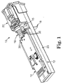
- Figure 1 is a perspective view of a transceiver module including an optical subassembly and heat wick in accordance with the present invention.
- Figure 2 illustrates an exploded view of an optical subassembly and heat wick in accordance with the present invention.
- Figure 3 illustrates a cross section of an optical subassembly and heat wick in accordance with the present invention.
- Figure 4 illustrates an end view of an optical subassembly and heat wick in accordance with the present invention.
- Figure 5 illustrates a perspective view of transceiver module with optical subassembly and heat wick in accordance with the present invention.
- Figure 6 illustrates a cross section of an optical subassembly and heat wick mounted to a housing in accordance with the present invention.
- Figure 7 illustrates a heat wick mounted to a housing in accordance with the present invention.
- Figure 8 illustrates a perspective view of an alternative embodiment of a transceiver module with optical subassembly and heat wick in accordance with the present invention.
- Transceiver module 10 includes housing 12, printed circuit board 14, first optical subassembly 15, second optical subassembly 16, and heat wick 18.
- the various components of transceiver module 10 are assembled and then connected to optical connectors, such a fiber optic cable, on one side and to a host system, such as a router, computer or other electrical device, on another.
- Transceiver module 10 then transforms electrical signals to optical signals and/or transforms optical signals into electrical signals.
- two optical subassemblies 15 and 16 are placed within transceiver module 10, one a transmit subassembly and one a receive subassembly. It is also possible to have a single optical subassembly in accordance with the present invention as well.
- Housing 12 includes a nose portion 22 and a frame portion 23.
- Printed circuit board 14 is mounted to frame portion 23 and optical subassemblies 15 and 16 are mounted between circuit board 14 and nose portion 22.
- Optical subassemblies 15 and 16 are mounted such that one end of each can be coupled to the circuit board 14 and another end of each couples into nose portion 22.
- Optical subassemblies 15 and 16 may be secured by a seat or nest on frame portion 23 such that they are mechanically supported on housing 12.
- Circuit board 14 carries various components thereon. Typically, these components include semiconductor chips and related electrical circuitry that facilitate the processing of electrical and optical signal conversion.
- Optical subassemblies 15 and 16 illustrated in Figure 1 include leads 35 projecting from the subassemblies that are connected directly to circuit board 14.
- flex leads (not shown in Figure 1) that are made of a conducting material can be used and configured to electrically couple circuit board 14 with optical subassemblies 15 and 16.
- optical subassemblies 15 and 16 functions as an optical transmitter and the other functions as an optical receiver, and each include subassembly leads 35. Leads 35 are electrically coupled to circuit board 14 when transceiver module 10 is fully assembled.
- Optical subassemblies 15 and 16 may include a photodiode or similar optical receiver, for transforming optical signals to electrical signals.
- Optical subassemblies 15 and 16 may also, or alternatively, include a laser, pin diode, or a similar optical emitter for transforming electrical signals to optical signals.
- a single optical subassembly is used, the single optical subassembly being a bidirectional optical subassembly.
- an optical subassembly is functioning as an optical transmitter or as an optical receiver, it will contain some sort of optoelectronic device, such as a photodiode or a laser. Consequently, it will generate significant heat during operation.
- Heat wick 18 is configured to be assembled to optical subassembly 15 and/or to optical subassembly 16 in accordance with the present invention. When completely assembled, heat wick 18 conductively couples optical assembly 15 and/or 16 with housing 12. Heat wick 18 thereby provides an efficient thermal path from optical assembly 15 and/or 16, which tend to be hot, to housing 12, which tends to be relatively cooler. Heat wick 18 is configured to be flexible thereby providing variable position control.
- Figure 2 illustrates optical subassembly 16 and heat wick 18 in accordance with the present invention.
- Heat wick 18 is also connectable to optical subassembly 15 in the same way, but for succinctness of description, a single subassembly will be illustrated.
- Optical subassembly 16 includes subassembly barrel 36 and optical can 38.
- Optical can 38 includes end surface 42.
- Barrel collar 40 is configured to be placed over subassembly barrel 36.
- Optical can 38 is a cylindrical can containing a laser or pin diode used for optical conversion. Typically, there is also a lens over the top of the laser or diode such that optical can 38 forms a thematic enclosure.
- Optical subassembly 16 is assembled by coupling optical can 38 to subassembly barrel 36.
- Subassembly barrel 36 is typically plastic or stainless steel.
- Subassembly barrel 36 must be optically aligned with optical can 38. Consequently, the final alignment dimensions of optical subassembly 16 will not be determined until optical can 38 and subassembly barrel 36 have been optically aligned, typically using a laser-welding process.
- Subassembly leads 35 extend from the end surface 42 of optical can 38.
- Optical can 38 may be, for example, a TO-can.
- heat wick 18 is then assembled over optical assembly 16.
- heat wick 18 includes sleeve 44 and flange 46.
- Sleeve 44 is configured to compliment the external shape of optical can 38 such that heat wick 18, and specifically sleeve 44, may be readily mounted on optical can 38.
- flange 46 is configured to be a flexible material such that it may be bent or twisted in order to be installed in multiple configurations of transceiver module 10 in accordance with the present invention. This flexibility can be useful when the final alignment dimensions of optical subassembly 16 vary slightly based on the final optical alignment of optical can 38 and subassembly barrel 36. In this way, slight variations in the final alignment dimensions of optical subassembly 16 can be compensated for in the flexibility of heat wick 18 during its installation.
- FIGS 3 and 4 illustrate heat wick 18 mounted on optical subassembly 16 in cross-sectional and end views, respectively.
- Optical subassembly 16 includes subassembly barrel 36 coupled to optical can 38.
- Heat wick 18 is mounted to optical can 38. When heat wick 18 is so mounted, there is contact between back surface 42 and a portion of heat wick 18. In addition, there is thermal contact between sleeve 44 and optical can 38.
- heat wick 18 is fixed to back surface 42 of optical can 38 using conductive epoxy or silver-filled conductive epoxy. In other embodiments, heat wick 18 may be fixed using any of a variety of bonding materials, including solder or other forms of epoxy. It could also be coupled with a mechanical connection between back surface 42 and heat wick 18.
- sleeve 44 could be configured as a spring clip such that it clips over optical can 38.
- heat wick 18 is formed of a thin copper strip. Consequently, heat wick 18 provides a very efficient thermal path away from optical subassembly 16. It is also quite flexible for attachment to housing 12. In this way, once optical subassembly 16 is mounted in housing 12 of transceiver module 10, heat wick 18 can then be installed and bent into place.
- FIG. 5 illustrates transceiver module 10 as view from the opposite side illustrated in Figure 1.
- Transceiver module 10 is illustrated with circuit board 14, optical subassemblies 15 and 16 (subassembly 16 not readily visible in Figure 5), and heat wick 18 assembled with housing 12.
- Optical subassemblies 15 and 16 are typically fixed to circuit board 14 and the combined assembly is mounted onto frame portion housing 12.
- heat wick 18, which has been fixed to end surface 42 can be thermally coupled to housing 12 in a variety of ways.
- flange 46 of heat wick 18 may project through a slot 52 provided in housing surface 26.
- housing surface 26 may also have a recess 25 into which flange 46 may be received when it is bent over housing 12.
- Flange 46 may then be fixed to recess 25 in a variety of ways. For example, a piece of material may be stamped over flange 46 onto housing 12 to hold flange 46 into recess 25. Similarly, various epoxies and/or solders could be used to fix flange 46 to housing 12.
- Optical subassembly 16 and circuit board 14 are assembled within transceiver module 10 such that they are mechanically secured within transceiver module 10 independently of heat wick 18.
- heat wick 18 is not relied upon to provide mechanical stability or support for optical subassembly 16 or circuit board 14 within transceiver module 10, but rather, only to thermally couple optical subassembly 16 to housing 12.
- This provides added flexibility in the assembly process in that there are no mechanical restrictions in thermally coupling optical subassembly 16 to housing 12 with heat wick 18. Since heat wick 18 is not relied upon for mechanical stability, it can be thermally coupled between optical subassembly 16 to housing 12 in a variety of ways consistent with the present invention.
- Figures 6 and 7 illustrate optical subassembly 16 being thermally coupled to housing 12 via heat wick 18.
- slot 52 may be provided in housing 12 immediately adjacent the location where heat wick 18 is mounted to optical subassembly 16. Upon installation, heat wick 18 is directed through slot 52. Once flange 46 of heat wick 18 is extended through slot 52, it may be bent over onto the surface 26 of housing 12.
- a recess 25 may be provided on the surface 26 of housing 12 configured to receive flange 46 of heat wick 18. Further, a cover 50 may be provided and configured to also be received in recess 25 to secure flange 46 against housing 12.
- heat wick 18 has sleeve 44 and flange 46, where flange portion 46 originally extends straight up from sleeve 44 when heat wick 18 is added to optical subassembly 16.
- Flange 46 may be bendable so that once optical subassembly 16 is assembled on housing 12 and heat wick 18 is then added to optical subassembly 16, flange 46 may be bent over against housing 12 to make a good thermal connection. Configuring flange 46 to be flexible or bendable allows flexibility on the assembly of transceiver 10.
- Various configurations and combinations of housings 12, circuit boards 14, and optical subassembly 16 may be accommodated in accordance with the present invention.
- optically aligning can 38 and optical barrel 36 can cause variation in the physical distance that can 38 is from housing 12, as can slight design changes that exist from transceiver to transceiver.
- Using heat wick 18, with flexible flange 46 allows differing sizes and dimensions for housings 12, circuit boards 14, and optical subassemblies 15 and 16 to be accommodated and for flange 46 to be bent over onto housing 12 to form an effective thermal path from optical subassemblies 15 and 16 to housing 12.
- Thermally coupling optical subassemblies 15 and 16 to housing 12 allows an efficient thermal path from hot optical devices to a relatively cool transceiver package.
- can 38, and specifically, end surface 42 of optical can 38 is the hottest portion of optical subassembly 15 and 16.
- Optical can 38, such as a TO-can is typically metallic and is the focal point for heat generated in optical subassembly 15 and 16, since it contains the laser or pin diode. Fixing heat wick 18 directly to this end surface 42 wicks heat away at the highest source of heat.
- Housing 12 is typically a zinc die cast or similar material, which provides a good source for dissipating heat.
- housing 12 is the largest heat conducting element in a transceiver further adding to its good heat-dissipating characteristics. Wicking the heat away from optical subassembly 15 and 16 will improve the overall performance of transceiver 10 by keeping the laser or pin diode cooler than it would be in the absence of heat wick 18.
- optical barrel 36 can be made of stainless steel, often it may be made of plastic or similar relatively poor conducting materials. Even where optical barrel 36 is made of stainless steel, it will not dissipate heat as well as a direct connection of heat wick 18 from end surface 42 of optical subassembly 16 to housing 12. Typically, stainless steel would have a thermal conductivity of approximately 18 watts per meter Kelvin. On the other hand, housing 12 made of zinc die cast material typically has high thermal conductivity of about 100 watts per meter Kelvin. Housing 12 is also typically a much larger size relative to optical barrel 36 thereby making a good heat sink for the heat generated within optical can 38. Heat wick 18 is typically made of copper having a conductivity of approximately 300 watts per meter Kelvin.
- Figure 8 illustrates and alternative embodiment of transceiver module 60 with circuit board 64, optical subassembly 66, and heat wick 68 assembled with housing 62.
- a single optical subassembly 66 is used to receive or to transmit.
- the present invention is not restricted to a particular number of optical assemblies used in the particular transceiver, or even the number of optical assemblies that are coupled to the housing with a heat wick.
- optical subassembly 66 is typically fixed to circuit board 64 and the combined assembly is mounted onto frame portion 73 of housing 62.
- Optical subassembly 66 is configured to rest in seat 70 and to extend into nose 72 such that a fiber cable connector can interface therewith.
- heat wick 68 which has been fixed to an end surface of optical subassembly 66, can be thermally coupled to housing 62 in a variety of ways. For example, a top portion of heat wick 68 may be bent over nose 72 once optical subassembly 66 is fixed in seat 70.
- Recess 75 may be provided into which the top portion of heat wick 68 may be received when it is bent over nose 72.
- the top portion of heat wick 68 may then be fixed to recess 75 in a variety of ways. For example, a piece of material may be stamped over heat wick 68 onto nose surface 74 to hold heat wick 68 onto nose 72. Similarly, various epoxies and/or solders could be used to fix heat wick 68 to nose 72.
- Optical subassembly 66 and circuit board 64 are assembled within transceiver module 60 such that they are mechanically secured within transceiver module 60 independently of heat wick 68.
- transceiver 60 illustrated in Figure 8 optical subassembly 66 is mechanically secured to transceiver module 60 via nest 70.
- heat wick 68 is not relied upon to provide mechanical stability or support for optical subassembly 66 or circuit board 64 within transceiver module 60, but rather, only to thermally couple optical subassembly 66 to housing 62.
- This provides added flexibility in the assembly process in that there are no mechanical restrictions in thermally coupling optical subassembly 66 to housing 62 with heat wick 68. Since heat wick 68 is not relied upon for mechanical stability, it can be thermally coupled between optical subassembly 66 to housing 62 in a variety of ways consistent with the present invention.
Landscapes
- Physics & Mathematics (AREA)
- General Physics & Mathematics (AREA)
- Optics & Photonics (AREA)
- Optical Couplings Of Light Guides (AREA)
Applications Claiming Priority (2)
| Application Number | Priority Date | Filing Date | Title |
|---|---|---|---|
| US10/761,106 US7308206B2 (en) | 2004-01-20 | 2004-01-20 | Heatsinking of optical subassembly and method of assembling |
| US761106 | 2004-01-20 |
Publications (3)
| Publication Number | Publication Date |
|---|---|
| EP1557704A2 true EP1557704A2 (de) | 2005-07-27 |
| EP1557704A3 EP1557704A3 (de) | 2005-08-03 |
| EP1557704B1 EP1557704B1 (de) | 2015-03-11 |
Family
ID=34634568
Family Applications (1)
| Application Number | Title | Priority Date | Filing Date |
|---|---|---|---|
| EP05075047.0A Expired - Fee Related EP1557704B1 (de) | 2004-01-20 | 2005-01-06 | Kühlkörperelement für optische Baugruppe und Zusammenbauverfahren |
Country Status (2)
| Country | Link |
|---|---|
| US (1) | US7308206B2 (de) |
| EP (1) | EP1557704B1 (de) |
Cited By (1)
| Publication number | Priority date | Publication date | Assignee | Title |
|---|---|---|---|---|
| GB2428134A (en) * | 2005-07-07 | 2007-01-17 | Agilent Technologies Inc | Optical transceiver with heat sink |
Families Citing this family (14)
| Publication number | Priority date | Publication date | Assignee | Title |
|---|---|---|---|---|
| JP4134695B2 (ja) * | 2002-11-21 | 2008-08-20 | 住友電気工業株式会社 | 光モジュール |
| US7365923B2 (en) * | 2004-01-26 | 2008-04-29 | Jds Uniphase Corporation | Heat sink tab for optical sub-assembly |
| JP4525478B2 (ja) * | 2004-06-16 | 2010-08-18 | 住友電気工業株式会社 | 放熱フィンを備えた光サブアセンブリ |
| US20060056850A1 (en) * | 2004-09-02 | 2006-03-16 | Infineon Technologies North America Corp. | Single width LC bi-directional transceiver |
| JP4403964B2 (ja) * | 2004-12-28 | 2010-01-27 | 日立電線株式会社 | 光トランシーバ |
| US7559704B2 (en) * | 2006-04-05 | 2009-07-14 | Finisar Corporation | Horseshoe spring for securing an optical nosepiece during optical alignment |
| US8920048B2 (en) * | 2009-05-19 | 2014-12-30 | Finisar Corporation | Communications module with a shell assembly having thermal mechanical features |
| USD630745S1 (en) | 2009-12-23 | 2011-01-11 | Intubrite, Llc | Laryngoscope blade |
| EP2859391B1 (de) | 2012-04-19 | 2022-11-30 | OE Solutions America Inc. | Kühlungssystem für vorrichtungen und baugruppen |
| WO2015187748A1 (en) * | 2014-06-02 | 2015-12-10 | Corsair Memory, Inc. | Graphics card cooler |
| US10371909B2 (en) * | 2016-03-11 | 2019-08-06 | Finisar Corporation | Thermal interface |
| CN115421258B (zh) * | 2017-07-19 | 2024-02-23 | 苏州旭创科技有限公司 | 光模块 |
| JP7192343B2 (ja) | 2018-09-20 | 2022-12-20 | 住友電気工業株式会社 | 光トランシーバ |
| JP7379854B2 (ja) | 2019-04-19 | 2023-11-15 | 住友電気工業株式会社 | 光トランシーバ |
Citations (2)
| Publication number | Priority date | Publication date | Assignee | Title |
|---|---|---|---|---|
| US5032898A (en) | 1979-12-10 | 1991-07-16 | Amp Incorporated | Electro-optic device assembly having integral heat sink/retention means |
| US6200041B1 (en) | 1997-09-12 | 2001-03-13 | International Business Machines Corporation | Data transfer system incorporating optical fiber link module with internal electromagnetic shield |
Family Cites Families (12)
| Publication number | Priority date | Publication date | Assignee | Title |
|---|---|---|---|---|
| JPS5630111A (en) | 1979-08-21 | 1981-03-26 | Nec Corp | Receptacle for optical communication |
| US4547039A (en) * | 1982-04-16 | 1985-10-15 | Amp Incorporated | Housing mountable on printed circuit board to interconnect fiber optic connectors |
| US5513073A (en) | 1994-04-18 | 1996-04-30 | International Business Machines Corporation | Optical device heat spreader and thermal isolation apparatus |
| US5631987A (en) * | 1995-06-07 | 1997-05-20 | Reliaspeed, Inc. | Low cost, mode-field matched, high performance laser transmitter optical subassembly |
| JPH11345987A (ja) * | 1998-06-02 | 1999-12-14 | Sony Corp | 光リンク用送受信モジュール実装方法及びそのリジッド・フレキシブル基板 |
| US6843606B2 (en) * | 2000-11-14 | 2005-01-18 | National Semiconductor Corporation | Multi-format connector module incorporating chip mounted optical sub-assembly |
| JP2002365487A (ja) * | 2001-01-18 | 2002-12-18 | Auto Network Gijutsu Kenkyusho:Kk | 光コネクタ及び光コネクタ用のシールドケース |
| CA2373675A1 (en) | 2001-02-28 | 2002-08-28 | Sumitomo Electric Industries, Ltd. | Optical data link |
| WO2002088810A1 (en) * | 2001-05-01 | 2002-11-07 | Corona Optical Systems, Inc. | Alignment apertures in an optically transparent substrate |
| TW468795U (en) * | 2001-05-30 | 2001-12-11 | Delta Electronics Inc | Optical transceiver |
| JP3982362B2 (ja) * | 2002-08-23 | 2007-09-26 | 住友電気工業株式会社 | 光データリンク |
| US6940723B2 (en) * | 2003-07-08 | 2005-09-06 | Finisar Corporation | Heat spreader for optical transceiver components |
-
2004
- 2004-01-20 US US10/761,106 patent/US7308206B2/en not_active Expired - Lifetime
-
2005
- 2005-01-06 EP EP05075047.0A patent/EP1557704B1/de not_active Expired - Fee Related
Patent Citations (2)
| Publication number | Priority date | Publication date | Assignee | Title |
|---|---|---|---|---|
| US5032898A (en) | 1979-12-10 | 1991-07-16 | Amp Incorporated | Electro-optic device assembly having integral heat sink/retention means |
| US6200041B1 (en) | 1997-09-12 | 2001-03-13 | International Business Machines Corporation | Data transfer system incorporating optical fiber link module with internal electromagnetic shield |
Cited By (1)
| Publication number | Priority date | Publication date | Assignee | Title |
|---|---|---|---|---|
| GB2428134A (en) * | 2005-07-07 | 2007-01-17 | Agilent Technologies Inc | Optical transceiver with heat sink |
Also Published As
| Publication number | Publication date |
|---|---|
| EP1557704B1 (de) | 2015-03-11 |
| EP1557704A3 (de) | 2005-08-03 |
| US7308206B2 (en) | 2007-12-11 |
| US20050158052A1 (en) | 2005-07-21 |
Similar Documents
| Publication | Publication Date | Title |
|---|---|---|
| US7308206B2 (en) | Heatsinking of optical subassembly and method of assembling | |
| JP5533431B2 (ja) | 光モジュール | |
| US8297856B2 (en) | Electro-optical module and multi-functional latch member therefor | |
| CN105911652B (zh) | 具有从组件基板直接至顶部壳体的散热路径的光收发器 | |
| US8104977B2 (en) | Pluggable transceiver with bi-directional optical sub-assembly | |
| JP5943372B2 (ja) | 小型高速光モジュール | |
| US7365923B2 (en) | Heat sink tab for optical sub-assembly | |
| CN113296202B (zh) | 光模块 | |
| US20040120660A1 (en) | Optical device and optical module | |
| JP2012064936A (ja) | 光モジュールおよびその組立方法 | |
| US7364373B2 (en) | Optical transceiver consistently satisfying optical alignment and heat-dissipation | |
| US20130299683A1 (en) | Optical connecting member and optical module | |
| US20080226239A1 (en) | Optical transceiver with mechanism to dissipate heat efficiently without affecting optical coupling condition | |
| US6863451B2 (en) | Optical module | |
| US7066661B2 (en) | Small footprint optical fiber transceiver | |
| JP2010008588A (ja) | 光トランシーバ | |
| WO2011152555A1 (en) | Optical transceiver with block to dissipate heat from tosa to cover | |
| JPH053330A (ja) | 光送受信モジユール | |
| US7367718B2 (en) | Optical module | |
| JP2012145617A (ja) | 光モジュール | |
| US6840685B1 (en) | Optical module and connecting construction for optical module | |
| JPH10247741A (ja) | 光通信用発光モジュールおよびその組立方法 | |
| JP4600246B2 (ja) | 光送受信モジュール及び光通信装置 | |
| JP3586574B2 (ja) | 光通信モジュール | |
| JP5109833B2 (ja) | 光トランシーバ |
Legal Events
| Date | Code | Title | Description |
|---|---|---|---|
| PUAI | Public reference made under article 153(3) epc to a published international application that has entered the european phase |
Free format text: ORIGINAL CODE: 0009012 |
|
| PUAL | Search report despatched |
Free format text: ORIGINAL CODE: 0009013 |
|
| AK | Designated contracting states |
Kind code of ref document: A2 Designated state(s): AT BE BG CH CY CZ DE DK EE ES FI FR GB GR HU IE IS IT LI LT LU MC NL PL PT RO SE SI SK TR |
|
| AX | Request for extension of the european patent |
Extension state: AL BA HR LV MK YU |
|
| AK | Designated contracting states |
Kind code of ref document: A3 Designated state(s): AT BE BG CH CY CZ DE DK EE ES FI FR GB GR HU IE IS IT LI LT LU MC NL PL PT RO SE SI SK TR |
|
| AX | Request for extension of the european patent |
Extension state: AL BA HR LV MK YU |
|
| 17P | Request for examination filed |
Effective date: 20060110 |
|
| AKX | Designation fees paid |
Designated state(s): DE FR GB |
|
| RAP1 | Party data changed (applicant data changed or rights of an application transferred) |
Owner name: FINISAR CORPORATION |
|
| 17Q | First examination report despatched |
Effective date: 20071221 |
|
| GRAP | Despatch of communication of intention to grant a patent |
Free format text: ORIGINAL CODE: EPIDOSNIGR1 |
|
| INTG | Intention to grant announced |
Effective date: 20140924 |
|
| GRAS | Grant fee paid |
Free format text: ORIGINAL CODE: EPIDOSNIGR3 |
|
| GRAA | (expected) grant |
Free format text: ORIGINAL CODE: 0009210 |
|
| AK | Designated contracting states |
Kind code of ref document: B1 Designated state(s): DE FR GB |
|
| REG | Reference to a national code |
Ref country code: GB Ref legal event code: FG4D |
|
| REG | Reference to a national code |
Ref country code: DE Ref legal event code: R096 Ref document number: 602005046023 Country of ref document: DE Effective date: 20150423 |
|
| REG | Reference to a national code |
Ref country code: DE Ref legal event code: R097 Ref document number: 602005046023 Country of ref document: DE |
|
| PLBE | No opposition filed within time limit |
Free format text: ORIGINAL CODE: 0009261 |
|
| STAA | Information on the status of an ep patent application or granted ep patent |
Free format text: STATUS: NO OPPOSITION FILED WITHIN TIME LIMIT |
|
| 26N | No opposition filed |
Effective date: 20151214 |
|
| REG | Reference to a national code |
Ref country code: DE Ref legal event code: R119 Ref document number: 602005046023 Country of ref document: DE |
|
| GBPC | Gb: european patent ceased through non-payment of renewal fee |
Effective date: 20160106 |
|
| REG | Reference to a national code |
Ref country code: FR Ref legal event code: ST Effective date: 20160930 |
|
| PG25 | Lapsed in a contracting state [announced via postgrant information from national office to epo] |
Ref country code: DE Free format text: LAPSE BECAUSE OF NON-PAYMENT OF DUE FEES Effective date: 20160802 Ref country code: GB Free format text: LAPSE BECAUSE OF NON-PAYMENT OF DUE FEES Effective date: 20160106 |
|
| PG25 | Lapsed in a contracting state [announced via postgrant information from national office to epo] |
Ref country code: FR Free format text: LAPSE BECAUSE OF NON-PAYMENT OF DUE FEES Effective date: 20160201 |