EP1557688A1 - Système de mesure acoustique permettant de localiser des sources de bruit - Google Patents
Système de mesure acoustique permettant de localiser des sources de bruit Download PDFInfo
- Publication number
- EP1557688A1 EP1557688A1 EP05356001A EP05356001A EP1557688A1 EP 1557688 A1 EP1557688 A1 EP 1557688A1 EP 05356001 A EP05356001 A EP 05356001A EP 05356001 A EP05356001 A EP 05356001A EP 1557688 A1 EP1557688 A1 EP 1557688A1
- Authority
- EP
- European Patent Office
- Prior art keywords
- microphones
- noise
- groups
- group
- different
- Prior art date
- Legal status (The legal status is an assumption and is not a legal conclusion. Google has not performed a legal analysis and makes no representation as to the accuracy of the status listed.)
- Granted
Links
Images

Classifications
-
- G—PHYSICS
- G01—MEASURING; TESTING
- G01S—RADIO DIRECTION-FINDING; RADIO NAVIGATION; DETERMINING DISTANCE OR VELOCITY BY USE OF RADIO WAVES; LOCATING OR PRESENCE-DETECTING BY USE OF THE REFLECTION OR RERADIATION OF RADIO WAVES; ANALOGOUS ARRANGEMENTS USING OTHER WAVES
- G01S3/00—Direction-finders for determining the direction from which infrasonic, sonic, ultrasonic or electromagnetic waves, or particle emission, not having a directional significance, are being received
- G01S3/80—Direction-finders for determining the direction from which infrasonic, sonic, ultrasonic or electromagnetic waves, or particle emission, not having a directional significance, are being received using ultrasonic, sonic or infrasonic waves
- G01S3/802—Systems for determining direction or deviation from predetermined direction
- G01S3/803—Systems for determining direction or deviation from predetermined direction using amplitude comparison of signals derived from receiving transducers or transducer systems having differently-oriented directivity characteristics
- G01S3/8034—Systems for determining direction or deviation from predetermined direction using amplitude comparison of signals derived from receiving transducers or transducer systems having differently-oriented directivity characteristics wherein the signals are derived simultaneously
- G01S3/8036—Systems for determining direction or deviation from predetermined direction using amplitude comparison of signals derived from receiving transducers or transducer systems having differently-oriented directivity characteristics wherein the signals are derived simultaneously derived directly from separate directional systems
-
- G—PHYSICS
- G03—PHOTOGRAPHY; CINEMATOGRAPHY; ANALOGOUS TECHNIQUES USING WAVES OTHER THAN OPTICAL WAVES; ELECTROGRAPHY; HOLOGRAPHY
- G03H—HOLOGRAPHIC PROCESSES OR APPARATUS
- G03H3/00—Holographic processes or apparatus using ultrasonic, sonic or infrasonic waves for obtaining holograms; Processes or apparatus for obtaining an optical image from them
-
- H—ELECTRICITY
- H04—ELECTRIC COMMUNICATION TECHNIQUE
- H04R—LOUDSPEAKERS, MICROPHONES, GRAMOPHONE PICK-UPS OR LIKE ACOUSTIC ELECTROMECHANICAL TRANSDUCERS; ELECTRIC HEARING AIDS; PUBLIC ADDRESS SYSTEMS
- H04R1/00—Details of transducers, loudspeakers or microphones
- H04R1/20—Arrangements for obtaining desired frequency or directional characteristics
- H04R1/32—Arrangements for obtaining desired frequency or directional characteristics for obtaining desired directional characteristic only
- H04R1/40—Arrangements for obtaining desired frequency or directional characteristics for obtaining desired directional characteristic only by combining a number of identical transducers
- H04R1/406—Arrangements for obtaining desired frequency or directional characteristics for obtaining desired directional characteristic only by combining a number of identical transducers microphones
-
- H—ELECTRICITY
- H04—ELECTRIC COMMUNICATION TECHNIQUE
- H04R—LOUDSPEAKERS, MICROPHONES, GRAMOPHONE PICK-UPS OR LIKE ACOUSTIC ELECTROMECHANICAL TRANSDUCERS; ELECTRIC HEARING AIDS; PUBLIC ADDRESS SYSTEMS
- H04R2201/00—Details of transducers, loudspeakers or microphones covered by H04R1/00 but not provided for in any of its subgroups
- H04R2201/40—Details of arrangements for obtaining desired directional characteristic by combining a number of identical transducers covered by H04R1/40 but not provided for in any of its subgroups
- H04R2201/401—2D or 3D arrays of transducers
Definitions
- the present invention relates to a measuring system acoustics to locate noise sources and to measure them the intensity.
- a known device includes several microphones omnidirectional, for example the number of 24, arranged on a plane.
- the plane on which the microphones are located, is oriented substantially perpendicular to the presumed direction of the noise source.
- the microphones measure the sound pressure resulting from noise emission, and each provide a signal to a processing device. This device processing provides a hologram of noise sources.
- the hologram of noise sources is obtained by performing calculations at different points, the microphones measuring the sound pressure for each of the points, taking into account the phase shift of the distances of different microphones vis-à-vis the different measuring points.
- these devices are suitable for external noise measurements, for example to measure the sound of a motor on the bench, they are taken in default as soon as they are placed inside a cockpit because they do not know distinguish the waves that arrive in front of or behind the antenna formed by all the microphones.
- the hologram of noise sources is obtained by performing calculations at different points, the microphones measuring the sound pressure for each of the points, taking into account the phase shift of the distances of different microphones vis-à-vis the different measuring points.
- the technical problem underlying the invention is to provide a system which allows the precise and simple localization of sources of noise inside an enclosure.
- the system it concerns comprises a plurality of microphones oriented in several directions and mounted in a support so that everyone is flush with a rigid surface, the different microphones being connected to a signal processing device.
- Each microphone "sees” especially the sources of noise placed in look, rigid body acting as screen for noise sources placed behind the rigid body, relative to the microphone considered.
- the phase shift must be taken into account between the different microphones due not only to the distance between the different microphones and the computation point, but also to the presence of the body rigid, acoustic waves not passing through the rigid surface, but bypassing this one. This results in an increase in travel time of the acoustic wave, for microphones located behind the rigid body, by relative to the noise source, which allows an increase in the phase shift between the different microphones and consequently an increase in the resolution at the location of the noise source.
- the support of the microphones is coated with a absorbent material, such as cellular foam.
- the support of microphones is constituted by a sphere.
- the different microphones are distributed on the surface of the sphere.
- the sphere has the advantage that it is a natural form whose behavior is easy to model. For a given source position, we can calculate, for each frequency, the module and the phase of the pressure acoustic measured by each microphone.
- the support of microphones consists of two parallel disks linked together by a portion of the toric surface, the microphones being placed in the disks.
- This second embodiment has the advantage of good separate the two half spaces.
- support rigid may have for example the shape of an ellipsoid or a parallelepiped.
- the measuring system consists for each group of microphones, to perform a signal processing from these microphones, to provide a hologram of the sources of noise, i.e. a distribution of the pressures or acoustic intensities in different points of the same surface.
- the system according to the invention consists, before performing a measurement, to divide a certain number of microphones belonging to one or two supports, in two groups.
- This distribution of a number of microphones belonging to one or two supports, in two groups, allows to carry out for the two groups of microphones a differential treatment of the signals from the different microphones of the two groups.
- This differential treatment may represent the functioning of the human ear.
- this system consists of perform focus processing for each group of microphones in every point where we want to know if there is a source of noise, then to perform for each calculation point the difference between the focused signals of the two groups, this difference being zero when the calculation point corresponds to the location of the noise source.
- this system consists of perform focus processing for a group of microphones in different points, located on the side of this group, in order to determine the existence of noise sources in these different points, and to perform, for the other group of microphones focusing treatment at opposite points of first, then to perform for each group of two points the difference between the focused signals of the two groups, this difference being maximum when the calculation point corresponds to the location of the noise source.
- FIG. 1 represents a sphere 2 made of rigid material, and whose outer surface may be coated with a cushioning material, such as foam, or can be perforated. Inside the sphere 2 are mounted 24 microphones 3, each of which is flush with the surface of the sphere 2.
- Figures 2 and 3 show an alternative embodiment of this system in which the rigid body has a different shape, and is consisting of two flat disks 4 interconnected by a torus portion 5. As shown in FIG. 3, the microphones 3 are flush with the surfaces of the two discs. This achievement has the advantage of separating the two half spaces.
- Figures 4 and 5 show the device of Figure 1, that is to say a sphere 2 equipped with a certain number of microphones, in this case 24. Some microphones are associated to form a group 6, while other microphones are associated to form a group 7. It should be noted that groups 6 and 7 do not necessarily contain all the microphones of sphere 2. It should also be noted that this grouping is a virtual grouping and not physical, this grouping being realized at the level of of the signal processing received by the different microphones of the two groups 6 and 7.
- Figures 4 and 5 show the implementation of a treatment said differential.
- the treatment makes it possible to estimate the position of the source maximum noise.
- a differential estimator For each point where we want to know if there is a source of noise, a differential estimator must be calculated as follows. It is first of all a focusing treatment for the same point of C calculation for both groups 6 and 7 of microphones. We calculate the function difference of the two results of the groups of microphones. This calculation is repeated for all the points where we want to know if there is a source. In the embodiment shown in FIG. 4, the focus is on the same point C for both groups 6 and 7, and the difference function is when the calculation point C is located at the position of the source of the noise.
- FIG. 5 represents a variant embodiment in which the same elements are designated by the same references as before.
- a focusing treatment is performed for group 6 of microphones, at a point P1 which is the point we are looking for if it corresponds at the source of noise, while the focus for the microphones of the group 7 is made at a point P2 located on the side opposite the point P1.
- the difference function is maximum when the point of P1 calculation is located at the position of the actual source of noise.
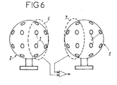
- FIG. 6 represents a variant embodiment in which the Groups 6 and 7 of microphones 3 belong to two distinct spheres 2.
- the invention provides a great improvement to the existing technique, providing a structural device simple way of determining the location of a source of noise and of measure the intensity, including inside a passenger compartment by distinguishing waves that arrive in front of or behind the antenna formed by different microphones, and by providing an improved signal processing mode still the conditions of location of a source of noise.
Landscapes
- Physics & Mathematics (AREA)
- Engineering & Computer Science (AREA)
- General Physics & Mathematics (AREA)
- Health & Medical Sciences (AREA)
- Otolaryngology (AREA)
- Radar, Positioning & Navigation (AREA)
- Remote Sensing (AREA)
- Acoustics & Sound (AREA)
- Signal Processing (AREA)
- Measurement Of Mechanical Vibrations Or Ultrasonic Waves (AREA)
- Measurement Of Velocity Or Position Using Acoustic Or Ultrasonic Waves (AREA)
Abstract
Description
Claims (8)
- Système de mesure acoustique permettant de localiser des sources de bruit et d'en mesurer l'intensité, caractérisé en ce qu'il comprend une pluralité de microphones (3) orientés suivant plusieurs directions et montés dans un support (2) de façon que chacun affleure une surface rigide, les différents microphones (3) étant reliés à un dispositif de traitement du signal, un traitement des signaux issus de ces microphones (3) pour fournir un hologramme des sources de bruit, c'est-à-dire une répartition des pressions ou intensités acoustiques en différents points d'une même surface.
- Système selon la revendication 1, caractérisé en ce que le support (2) des microphones (3) est revêtu d'un matériau absorbant, tel qu'une mousse cellulaire
- Système selon l'une des revendications 1 et 2, caractérisé en ce que le support des microphones est constitué par une sphère (2).
- Système selon l'une des revendications 1 et 2, caractérisé en ce que le support des microphones est constitué par deux disques parallèles (4) reliés entre eux par une portion de surface torique (5), les microphones (3) étant placés dans les disques (4).
- Système selon l'une des revendications 1 à 4, caractérisé en ce qu'il consiste, avant réalisation d'une mesure, à répartir un certain nombre de microphones (3) appartenant à un seul ou à deux supports (2), en deux groupes (6, 7).
- Système selon la revendication 5, caractérisé en ce qu'il consiste à effectuer pour les deux groupes (6, 7) de microphones un traitement différentiel des signaux issus des différents microphones (3) des deux groupes.
- Système selon la revendication 6, caractérisé en ce qu'il consiste à effectuer un traitement de focalisation pour chaque groupe (6, 7) de microphones (3) en chaque point (C) où l'on souhaite savoir s'il existe une source de bruit, puis à effectuer pour chaque point de calcul la différence entre les signaux focalisés des deux groupes (6, 7), cette différence étant nulle lorsque le point de calcul (C) correspond à l'emplacement de la source de bruit.
- Système selon la revendication 6, caractérisé en ce qu'il consiste à effectuer un traitement de focalisation pour un groupe (6, 7) de microphones (3) en différents points (P1) situés du côté de ce groupe (6), en vue de déterminer l'existence de sources de bruit en ces différents points, et à effectuer, pour l'autre groupe (7) de microphones (3) un traitement de focalisation en des points (P2) opposés des premiers, puis à effecteur pour chaque groupe (6, 7) de deux points la différence entre les signaux focalisés des deux groupes, cette différence étant maximale lorsque le point de calcul correspond à l'emplacement de la source de bruit.
Applications Claiming Priority (2)
| Application Number | Priority Date | Filing Date | Title |
|---|---|---|---|
| FR0400202 | 2004-01-09 | ||
| FR0400202A FR2865040B1 (fr) | 2004-01-09 | 2004-01-09 | Systeme de mesure acoustique permettant de localiser des sources de bruit |
Publications (2)
| Publication Number | Publication Date |
|---|---|
| EP1557688A1 true EP1557688A1 (fr) | 2005-07-27 |
| EP1557688B1 EP1557688B1 (fr) | 2009-04-08 |
Family
ID=34630641
Family Applications (1)
| Application Number | Title | Priority Date | Filing Date |
|---|---|---|---|
| EP05356001A Expired - Lifetime EP1557688B1 (fr) | 2004-01-09 | 2005-01-03 | Système de mesure acoustique permettant de localiser des sources de bruit |
Country Status (6)
| Country | Link |
|---|---|
| US (1) | US7817804B2 (fr) |
| EP (1) | EP1557688B1 (fr) |
| AT (1) | ATE428121T1 (fr) |
| DE (1) | DE602005013708D1 (fr) |
| DK (1) | DK1557688T3 (fr) |
| FR (1) | FR2865040B1 (fr) |
Cited By (3)
| Publication number | Priority date | Publication date | Assignee | Title |
|---|---|---|---|---|
| EP1840589A1 (fr) * | 2006-03-29 | 2007-10-03 | Microdb | Dispositif de localisation acoustique et de mesure de leur intensité |
| EP2485062A2 (fr) | 2011-02-04 | 2012-08-08 | Microdb | Dispositif de localisation acoustique |
| CN104571492A (zh) * | 2014-10-10 | 2015-04-29 | 上海大学 | 一种虚拟现实声渲染中球面声源表面的位置分布方法 |
Families Citing this family (8)
| Publication number | Priority date | Publication date | Assignee | Title |
|---|---|---|---|---|
| JP5123843B2 (ja) * | 2005-03-16 | 2013-01-23 | コクス,ジェイムズ | マイクロフォンアレイおよびデジタル信号処理システム |
| FR2896314B1 (fr) * | 2006-01-18 | 2008-02-22 | Microdb Sa | Dispositif de localisation de sources acoustiques et de mesure de leur intensite |
| WO2008042884A1 (fr) * | 2006-10-02 | 2008-04-10 | Wayne State University | Localisation de sources de bruit arbitraire |
| SE534042C2 (sv) * | 2009-08-19 | 2011-04-12 | Scania Cv Ab | Metod och anordning för att simulera akustiska emissioner från en motor |
| GB201321852D0 (en) * | 2013-12-10 | 2014-01-22 | Thales Holdings Uk Plc | Acoustic Detector |
| US10337757B2 (en) * | 2016-08-31 | 2019-07-02 | The Boeing Company | In-duct acoustic measuring apparatus and method |
| NO20211439A1 (no) * | 2021-11-26 | 2023-05-29 | Momentum Tech As | Støykartleggingsinnretning |
| CN115027675B (zh) * | 2022-06-21 | 2023-05-19 | 江汉大学 | 一种基于无人机平台用爆破现场噪声测量装置 |
Citations (4)
| Publication number | Priority date | Publication date | Assignee | Title |
|---|---|---|---|---|
| US4332979A (en) * | 1978-12-19 | 1982-06-01 | Fischer Mark L | Electronic environmental acoustic simulator |
| JPH0472525A (ja) | 1990-07-13 | 1992-03-06 | Nippon Telegr & Teleph Corp <Ntt> | 音源方向識別センサ |
| US6310832B1 (en) * | 1982-11-17 | 2001-10-30 | Raytheon Company | Interpolated beamforming tracker |
| US20030147539A1 (en) * | 2002-01-11 | 2003-08-07 | Mh Acoustics, Llc, A Delaware Corporation | Audio system based on at least second-order eigenbeams |
Family Cites Families (4)
| Publication number | Priority date | Publication date | Assignee | Title |
|---|---|---|---|---|
| JP3789685B2 (ja) * | 1999-07-02 | 2006-06-28 | 富士通株式会社 | マイクロホンアレイ装置 |
| JP2001166025A (ja) * | 1999-12-14 | 2001-06-22 | Matsushita Electric Ind Co Ltd | 音源の方向推定方法および収音方法およびその装置 |
| JP4722347B2 (ja) * | 2000-10-02 | 2011-07-13 | 中部電力株式会社 | 音源探査システム |
| US7248703B1 (en) * | 2001-06-26 | 2007-07-24 | Bbn Technologies Corp. | Systems and methods for adaptive noise cancellation |
-
2004
- 2004-01-09 FR FR0400202A patent/FR2865040B1/fr not_active Expired - Fee Related
-
2005
- 2005-01-03 AT AT05356001T patent/ATE428121T1/de not_active IP Right Cessation
- 2005-01-03 EP EP05356001A patent/EP1557688B1/fr not_active Expired - Lifetime
- 2005-01-03 DE DE602005013708T patent/DE602005013708D1/de not_active Expired - Lifetime
- 2005-01-03 DK DK05356001T patent/DK1557688T3/da active
- 2005-01-04 US US11/027,939 patent/US7817804B2/en not_active Expired - Fee Related
Patent Citations (4)
| Publication number | Priority date | Publication date | Assignee | Title |
|---|---|---|---|---|
| US4332979A (en) * | 1978-12-19 | 1982-06-01 | Fischer Mark L | Electronic environmental acoustic simulator |
| US6310832B1 (en) * | 1982-11-17 | 2001-10-30 | Raytheon Company | Interpolated beamforming tracker |
| JPH0472525A (ja) | 1990-07-13 | 1992-03-06 | Nippon Telegr & Teleph Corp <Ntt> | 音源方向識別センサ |
| US20030147539A1 (en) * | 2002-01-11 | 2003-08-07 | Mh Acoustics, Llc, A Delaware Corporation | Audio system based on at least second-order eigenbeams |
Non-Patent Citations (4)
| Title |
|---|
| PATENT ABSTRACTS OF JAPAN vol. 0162, no. 76 (P - 1374) 19 June 1992 (1992-06-19) * |
| VAUCHER DE LA CROIX D ET AL: "HOLOGRAPHIE ACOUSTIQUE APPLIQUEE A DES MESURES INTERIEURES 3D EN HABITACLE", INGENIEURS DE L'AUTOMOBILE, RAIP. BOULOGNE, FR, no. 741, November 2000 (2000-11-01), pages 132 - 136,139, XP000987553, ISSN: 0020-1200 * |
| WILLIAMS E ET AL.: "A prototype spherical array for interior noise investigations", JOURNAL OF THE ACOUSTIC SOCIETY OF AMERICA, vol. 112, no. 5, pages 2 |
| WILLIAMS E ET AL: "A prototype spherical array for interior noise investigations", JOURNAL OF THE ACOUSTIC SOCIETY OF AMERICA. VOL. 112, NO. 5, PART 2, November 2002 (2002-11-01), pages 2348, XP002325567, Retrieved from the Internet <URL:http://scitation.aip.org/jasa/> [retrieved on 20050421] * |
Cited By (6)
| Publication number | Priority date | Publication date | Assignee | Title |
|---|---|---|---|---|
| EP1840589A1 (fr) * | 2006-03-29 | 2007-10-03 | Microdb | Dispositif de localisation acoustique et de mesure de leur intensité |
| FR2899341A1 (fr) * | 2006-03-29 | 2007-10-05 | Microdb Sa | Dispositif de localisation acoustique et de mesure de leur intensite |
| EP2485062A2 (fr) | 2011-02-04 | 2012-08-08 | Microdb | Dispositif de localisation acoustique |
| US8923521B2 (en) | 2011-02-04 | 2014-12-30 | Microdb | Device for localizing acoustic sources and/or measuring their intensities |
| CN104571492A (zh) * | 2014-10-10 | 2015-04-29 | 上海大学 | 一种虚拟现实声渲染中球面声源表面的位置分布方法 |
| CN104571492B (zh) * | 2014-10-10 | 2017-12-05 | 上海大学 | 一种虚拟现实声渲染中球面声源表面的位置分布方法 |
Also Published As
| Publication number | Publication date |
|---|---|
| EP1557688B1 (fr) | 2009-04-08 |
| FR2865040B1 (fr) | 2006-05-05 |
| US7817804B2 (en) | 2010-10-19 |
| DK1557688T3 (da) | 2009-08-03 |
| ATE428121T1 (de) | 2009-04-15 |
| FR2865040A1 (fr) | 2005-07-15 |
| DE602005013708D1 (de) | 2009-05-20 |
| US20050163330A1 (en) | 2005-07-28 |
Similar Documents
| Publication | Publication Date | Title |
|---|---|---|
| EP0904535B1 (fr) | Procede et dispositif de detection et de localisation de source sonore reflechissante | |
| EP1557688B1 (fr) | Système de mesure acoustique permettant de localiser des sources de bruit | |
| CA2318378C (fr) | Transducteur ultrasonore de contact, a elements multiples | |
| US7266044B2 (en) | Method and apparatus for acoustic source tracking using a horizontal line array | |
| EP0150634B1 (fr) | Sonde pour l'échographie ultrasonore comportant une mosaique d'éléments définissant une surface convexe | |
| CA2786411A1 (fr) | Procede et dispositif d'acquisition de donnees sismiques marines | |
| FR2651950A1 (fr) | Antenne hydrophonique lineaire et dispositif electronique de levee d'ambiguite droite-gauche associe a cette antenne. | |
| Dall'Osto et al. | Measurement of acoustic particle motion in shallow water and its application to geoacoustic inversion | |
| WO2021023933A1 (fr) | Procédé et système de caractérisation ultrasonore non invasive d'un milieu hétérogène | |
| EP0015852B1 (fr) | Appareillage permettant la mesure de la puissance acoustique totale ou directive émise par une source quelconque | |
| EP1811346B1 (fr) | Dispositif de localisation de sources acoustiques et de mesure de leur intensité | |
| EP2018579B1 (fr) | Sonar frontal ameliore | |
| FR2732118A1 (fr) | Capteur a ultrasons et procedes de detection utilisant un tel capteur | |
| FR2845510A1 (fr) | Installation et procede de mesure acoustique par microphone repere dans l'espace | |
| FR2525774A1 (fr) | Dispositif de filtrage adaptatif de signaux recus par un sonar actif pour la rejection de la reverberation | |
| FR2590679A1 (fr) | Procede de determination passive de donnees de reperage d'un vehicule | |
| EP1840589A1 (fr) | Dispositif de localisation acoustique et de mesure de leur intensité | |
| FR2533790A1 (fr) | Appareil microphonique | |
| Gerstoft et al. | Phenomenological and global optimization inversion | |
| FR2489967A1 (fr) | Recepteur muni de plusieurs transducteurs pour sonar | |
| EP4197450B1 (fr) | Dispositif et procede d'evaluation d'activite cardiovasculaire par ultrasons | |
| Haxter et al. | Improving the performance of aeroacoustic measurements beneath a turbulent boundary layer in a wake flow | |
| Gebbie et al. | Extracting the Rayleigh reflection coefficient from the passive fathometer | |
| FR2714734A1 (fr) | Procédé de localisation acoustique d'un véhicule remorqué par un bateau. | |
| Son et al. | Underwater target echo signal separation using independent component analysis and principal component analysis |
Legal Events
| Date | Code | Title | Description |
|---|---|---|---|
| PUAI | Public reference made under article 153(3) epc to a published international application that has entered the european phase |
Free format text: ORIGINAL CODE: 0009012 |
|
| AK | Designated contracting states |
Kind code of ref document: A1 Designated state(s): AT BE BG CH CY CZ DE DK EE ES FI FR GB GR HU IE IS IT LI LT LU MC NL PL PT RO SE SI SK TR |
|
| AX | Request for extension of the european patent |
Extension state: AL BA HR LV MK YU |
|
| 17P | Request for examination filed |
Effective date: 20051219 |
|
| AKX | Designation fees paid |
Designated state(s): AT BE BG CH CY CZ DE DK EE ES FI FR GB GR HU IE IS IT LI LT LU MC NL PL PT RO SE SI SK TR |
|
| GRAP | Despatch of communication of intention to grant a patent |
Free format text: ORIGINAL CODE: EPIDOSNIGR1 |
|
| GRAS | Grant fee paid |
Free format text: ORIGINAL CODE: EPIDOSNIGR3 |
|
| GRAA | (expected) grant |
Free format text: ORIGINAL CODE: 0009210 |
|
| AK | Designated contracting states |
Kind code of ref document: B1 Designated state(s): AT BE BG CH CY CZ DE DK EE ES FI FR GB GR HU IE IS IT LI LT LU MC NL PL PT RO SE SI SK TR |
|
| REG | Reference to a national code |
Ref country code: GB Ref legal event code: FG4D Free format text: NOT ENGLISH |
|
| REG | Reference to a national code |
Ref country code: CH Ref legal event code: EP |
|
| REG | Reference to a national code |
Ref country code: IE Ref legal event code: FG4D |
|
| REF | Corresponds to: |
Ref document number: 602005013708 Country of ref document: DE Date of ref document: 20090520 Kind code of ref document: P |
|
| PG25 | Lapsed in a contracting state [announced via postgrant information from national office to epo] |
Ref country code: SI Free format text: LAPSE BECAUSE OF FAILURE TO SUBMIT A TRANSLATION OF THE DESCRIPTION OR TO PAY THE FEE WITHIN THE PRESCRIBED TIME-LIMIT Effective date: 20090408 |
|
| REG | Reference to a national code |
Ref country code: DK Ref legal event code: T3 |
|
| REG | Reference to a national code |
Ref country code: SE Ref legal event code: TRGR |
|
| NLV1 | Nl: lapsed or annulled due to failure to fulfill the requirements of art. 29p and 29m of the patents act | ||
| REG | Reference to a national code |
Ref country code: IE Ref legal event code: FD4D |
|
| PG25 | Lapsed in a contracting state [announced via postgrant information from national office to epo] |
Ref country code: LT Free format text: LAPSE BECAUSE OF FAILURE TO SUBMIT A TRANSLATION OF THE DESCRIPTION OR TO PAY THE FEE WITHIN THE PRESCRIBED TIME-LIMIT Effective date: 20090408 Ref country code: FI Free format text: LAPSE BECAUSE OF FAILURE TO SUBMIT A TRANSLATION OF THE DESCRIPTION OR TO PAY THE FEE WITHIN THE PRESCRIBED TIME-LIMIT Effective date: 20090408 Ref country code: ES Free format text: LAPSE BECAUSE OF FAILURE TO SUBMIT A TRANSLATION OF THE DESCRIPTION OR TO PAY THE FEE WITHIN THE PRESCRIBED TIME-LIMIT Effective date: 20090719 Ref country code: AT Free format text: LAPSE BECAUSE OF FAILURE TO SUBMIT A TRANSLATION OF THE DESCRIPTION OR TO PAY THE FEE WITHIN THE PRESCRIBED TIME-LIMIT Effective date: 20090408 Ref country code: PT Free format text: LAPSE BECAUSE OF FAILURE TO SUBMIT A TRANSLATION OF THE DESCRIPTION OR TO PAY THE FEE WITHIN THE PRESCRIBED TIME-LIMIT Effective date: 20090908 |
|
| PG25 | Lapsed in a contracting state [announced via postgrant information from national office to epo] |
Ref country code: PL Free format text: LAPSE BECAUSE OF FAILURE TO SUBMIT A TRANSLATION OF THE DESCRIPTION OR TO PAY THE FEE WITHIN THE PRESCRIBED TIME-LIMIT Effective date: 20090408 Ref country code: IS Free format text: LAPSE BECAUSE OF FAILURE TO SUBMIT A TRANSLATION OF THE DESCRIPTION OR TO PAY THE FEE WITHIN THE PRESCRIBED TIME-LIMIT Effective date: 20090808 Ref country code: NL Free format text: LAPSE BECAUSE OF FAILURE TO SUBMIT A TRANSLATION OF THE DESCRIPTION OR TO PAY THE FEE WITHIN THE PRESCRIBED TIME-LIMIT Effective date: 20090408 |
|
| PG25 | Lapsed in a contracting state [announced via postgrant information from national office to epo] |
Ref country code: EE Free format text: LAPSE BECAUSE OF FAILURE TO SUBMIT A TRANSLATION OF THE DESCRIPTION OR TO PAY THE FEE WITHIN THE PRESCRIBED TIME-LIMIT Effective date: 20090408 Ref country code: IE Free format text: LAPSE BECAUSE OF FAILURE TO SUBMIT A TRANSLATION OF THE DESCRIPTION OR TO PAY THE FEE WITHIN THE PRESCRIBED TIME-LIMIT Effective date: 20090408 Ref country code: CZ Free format text: LAPSE BECAUSE OF FAILURE TO SUBMIT A TRANSLATION OF THE DESCRIPTION OR TO PAY THE FEE WITHIN THE PRESCRIBED TIME-LIMIT Effective date: 20090408 Ref country code: RO Free format text: LAPSE BECAUSE OF FAILURE TO SUBMIT A TRANSLATION OF THE DESCRIPTION OR TO PAY THE FEE WITHIN THE PRESCRIBED TIME-LIMIT Effective date: 20090408 |
|
| PLBE | No opposition filed within time limit |
Free format text: ORIGINAL CODE: 0009261 |
|
| STAA | Information on the status of an ep patent application or granted ep patent |
Free format text: STATUS: NO OPPOSITION FILED WITHIN TIME LIMIT |
|
| PG25 | Lapsed in a contracting state [announced via postgrant information from national office to epo] |
Ref country code: SK Free format text: LAPSE BECAUSE OF FAILURE TO SUBMIT A TRANSLATION OF THE DESCRIPTION OR TO PAY THE FEE WITHIN THE PRESCRIBED TIME-LIMIT Effective date: 20090408 |
|
| 26N | No opposition filed |
Effective date: 20100111 |
|
| PG25 | Lapsed in a contracting state [announced via postgrant information from national office to epo] |
Ref country code: BG Free format text: LAPSE BECAUSE OF FAILURE TO SUBMIT A TRANSLATION OF THE DESCRIPTION OR TO PAY THE FEE WITHIN THE PRESCRIBED TIME-LIMIT Effective date: 20090708 |
|
| BERE | Be: lapsed |
Owner name: AIRBUS FRANCE Effective date: 20100131 Owner name: MICRODB Effective date: 20100131 |
|
| PG25 | Lapsed in a contracting state [announced via postgrant information from national office to epo] |
Ref country code: MC Free format text: LAPSE BECAUSE OF NON-PAYMENT OF DUE FEES Effective date: 20100131 |
|
| REG | Reference to a national code |
Ref country code: CH Ref legal event code: PL |
|
| PG25 | Lapsed in a contracting state [announced via postgrant information from national office to epo] |
Ref country code: GR Free format text: LAPSE BECAUSE OF FAILURE TO SUBMIT A TRANSLATION OF THE DESCRIPTION OR TO PAY THE FEE WITHIN THE PRESCRIBED TIME-LIMIT Effective date: 20090709 Ref country code: LI Free format text: LAPSE BECAUSE OF NON-PAYMENT OF DUE FEES Effective date: 20100131 Ref country code: CH Free format text: LAPSE BECAUSE OF NON-PAYMENT OF DUE FEES Effective date: 20100131 |
|
| PG25 | Lapsed in a contracting state [announced via postgrant information from national office to epo] |
Ref country code: BE Free format text: LAPSE BECAUSE OF NON-PAYMENT OF DUE FEES Effective date: 20100131 |
|
| REG | Reference to a national code |
Ref country code: GB Ref legal event code: 732E Free format text: REGISTERED BETWEEN 20110721 AND 20110727 |
|
| REG | Reference to a national code |
Ref country code: DE Ref legal event code: R082 Ref document number: 602005013708 Country of ref document: DE Representative=s name: PATENTANWAELTE MAGENBAUER & KOLLEGEN, DE |
|
| REG | Reference to a national code |
Ref country code: FR Ref legal event code: CD Owner name: AIRBUS OPERATIONS, FR Effective date: 20120313 Ref country code: FR Ref legal event code: CA Effective date: 20120313 Ref country code: FR Ref legal event code: CJ Effective date: 20120313 |
|
| REG | Reference to a national code |
Ref country code: DE Ref legal event code: R082 Ref document number: 602005013708 Country of ref document: DE Representative=s name: PATENTANWAELTE MAGENBAUER & KOLLEGEN PARTNERSC, DE Effective date: 20120326 Ref country code: DE Ref legal event code: R081 Ref document number: 602005013708 Country of ref document: DE Owner name: AIRBUS OPERATIONS SAS, FR Free format text: FORMER OWNER: MICRODB, AIRBUS FRANCE, , FR Effective date: 20120326 Ref country code: DE Ref legal event code: R081 Ref document number: 602005013708 Country of ref document: DE Owner name: MICRODB, FR Free format text: FORMER OWNER: MICRODB, AIRBUS FRANCE, , FR Effective date: 20120326 Ref country code: DE Ref legal event code: R082 Ref document number: 602005013708 Country of ref document: DE Representative=s name: PATENTANWAELTE MAGENBAUER & KOLLEGEN, DE Effective date: 20120326 Ref country code: DE Ref legal event code: R081 Ref document number: 602005013708 Country of ref document: DE Owner name: MICRODB, FR Free format text: FORMER OWNERS: MICRODB, ECULLY, FR; AIRBUS FRANCE, TOULOUSE, FR Effective date: 20120326 Ref country code: DE Ref legal event code: R081 Ref document number: 602005013708 Country of ref document: DE Owner name: AIRBUS OPERATIONS SAS, FR Free format text: FORMER OWNERS: MICRODB, ECULLY, FR; AIRBUS FRANCE, TOULOUSE, FR Effective date: 20120326 |
|
| PG25 | Lapsed in a contracting state [announced via postgrant information from national office to epo] |
Ref country code: CY Free format text: LAPSE BECAUSE OF FAILURE TO SUBMIT A TRANSLATION OF THE DESCRIPTION OR TO PAY THE FEE WITHIN THE PRESCRIBED TIME-LIMIT Effective date: 20090408 |
|
| PG25 | Lapsed in a contracting state [announced via postgrant information from national office to epo] |
Ref country code: HU Free format text: LAPSE BECAUSE OF FAILURE TO SUBMIT A TRANSLATION OF THE DESCRIPTION OR TO PAY THE FEE WITHIN THE PRESCRIBED TIME-LIMIT Effective date: 20091009 Ref country code: LU Free format text: LAPSE BECAUSE OF NON-PAYMENT OF DUE FEES Effective date: 20100103 |
|
| PG25 | Lapsed in a contracting state [announced via postgrant information from national office to epo] |
Ref country code: TR Free format text: LAPSE BECAUSE OF FAILURE TO SUBMIT A TRANSLATION OF THE DESCRIPTION OR TO PAY THE FEE WITHIN THE PRESCRIBED TIME-LIMIT Effective date: 20090408 |
|
| REG | Reference to a national code |
Ref country code: FR Ref legal event code: TP Owner name: AIRBUS HOLDING, FR Effective date: 20130322 |
|
| REG | Reference to a national code |
Ref country code: FR Ref legal event code: PLFP Year of fee payment: 12 |
|
| REG | Reference to a national code |
Ref country code: FR Ref legal event code: PLFP Year of fee payment: 13 |
|
| REG | Reference to a national code |
Ref country code: FR Ref legal event code: PLFP Year of fee payment: 14 |
|
| PGFP | Annual fee paid to national office [announced via postgrant information from national office to epo] |
Ref country code: GB Payment date: 20180119 Year of fee payment: 14 Ref country code: DE Payment date: 20180122 Year of fee payment: 14 Ref country code: DK Payment date: 20180119 Year of fee payment: 14 |
|
| PGFP | Annual fee paid to national office [announced via postgrant information from national office to epo] |
Ref country code: IT Payment date: 20180129 Year of fee payment: 14 Ref country code: SE Payment date: 20180119 Year of fee payment: 14 Ref country code: FR Payment date: 20180119 Year of fee payment: 14 |
|
| REG | Reference to a national code |
Ref country code: DE Ref legal event code: R119 Ref document number: 602005013708 Country of ref document: DE |
|
| REG | Reference to a national code |
Ref country code: DK Ref legal event code: EBP Effective date: 20190131 |
|
| GBPC | Gb: european patent ceased through non-payment of renewal fee |
Effective date: 20190103 |
|
| PG25 | Lapsed in a contracting state [announced via postgrant information from national office to epo] |
Ref country code: FR Free format text: LAPSE BECAUSE OF NON-PAYMENT OF DUE FEES Effective date: 20190131 Ref country code: DE Free format text: LAPSE BECAUSE OF NON-PAYMENT OF DUE FEES Effective date: 20190801 Ref country code: SE Free format text: LAPSE BECAUSE OF NON-PAYMENT OF DUE FEES Effective date: 20190104 |
|
| PG25 | Lapsed in a contracting state [announced via postgrant information from national office to epo] |
Ref country code: GB Free format text: LAPSE BECAUSE OF NON-PAYMENT OF DUE FEES Effective date: 20190103 |
|
| PG25 | Lapsed in a contracting state [announced via postgrant information from national office to epo] |
Ref country code: DK Free format text: LAPSE BECAUSE OF NON-PAYMENT OF DUE FEES Effective date: 20190131 |
|
| PG25 | Lapsed in a contracting state [announced via postgrant information from national office to epo] |
Ref country code: IT Free format text: LAPSE BECAUSE OF NON-PAYMENT OF DUE FEES Effective date: 20190103 |