EP1557688A1 - Acoustic measurement system for locating sources of noise - Google Patents
Acoustic measurement system for locating sources of noise Download PDFInfo
- Publication number
- EP1557688A1 EP1557688A1 EP05356001A EP05356001A EP1557688A1 EP 1557688 A1 EP1557688 A1 EP 1557688A1 EP 05356001 A EP05356001 A EP 05356001A EP 05356001 A EP05356001 A EP 05356001A EP 1557688 A1 EP1557688 A1 EP 1557688A1
- Authority
- EP
- European Patent Office
- Prior art keywords
- microphones
- noise
- groups
- group
- different
- Prior art date
- Legal status (The legal status is an assumption and is not a legal conclusion. Google has not performed a legal analysis and makes no representation as to the accuracy of the status listed.)
- Granted
Links
Images

Classifications
-
- G—PHYSICS
- G01—MEASURING; TESTING
- G01S—RADIO DIRECTION-FINDING; RADIO NAVIGATION; DETERMINING DISTANCE OR VELOCITY BY USE OF RADIO WAVES; LOCATING OR PRESENCE-DETECTING BY USE OF THE REFLECTION OR RERADIATION OF RADIO WAVES; ANALOGOUS ARRANGEMENTS USING OTHER WAVES
- G01S3/00—Direction-finders for determining the direction from which infrasonic, sonic, ultrasonic, or electromagnetic waves, or particle emission, not having a directional significance, are being received
- G01S3/80—Direction-finders for determining the direction from which infrasonic, sonic, ultrasonic, or electromagnetic waves, or particle emission, not having a directional significance, are being received using ultrasonic, sonic or infrasonic waves
- G01S3/802—Systems for determining direction or deviation from predetermined direction
- G01S3/803—Systems for determining direction or deviation from predetermined direction using amplitude comparison of signals derived from receiving transducers or transducer systems having differently-oriented directivity characteristics
- G01S3/8034—Systems for determining direction or deviation from predetermined direction using amplitude comparison of signals derived from receiving transducers or transducer systems having differently-oriented directivity characteristics wherein the signals are derived simultaneously
- G01S3/8036—Systems for determining direction or deviation from predetermined direction using amplitude comparison of signals derived from receiving transducers or transducer systems having differently-oriented directivity characteristics wherein the signals are derived simultaneously derived directly from separate directional systems
-
- G—PHYSICS
- G03—PHOTOGRAPHY; CINEMATOGRAPHY; ANALOGOUS TECHNIQUES USING WAVES OTHER THAN OPTICAL WAVES; ELECTROGRAPHY; HOLOGRAPHY
- G03H—HOLOGRAPHIC PROCESSES OR APPARATUS
- G03H3/00—Holographic processes or apparatus using ultrasonic, sonic or infrasonic waves for obtaining holograms; Processes or apparatus for obtaining an optical image from them
-
- H—ELECTRICITY
- H04—ELECTRIC COMMUNICATION TECHNIQUE
- H04R—LOUDSPEAKERS, MICROPHONES, GRAMOPHONE PICK-UPS OR LIKE ACOUSTIC ELECTROMECHANICAL TRANSDUCERS; DEAF-AID SETS; PUBLIC ADDRESS SYSTEMS
- H04R1/00—Details of transducers, loudspeakers or microphones
- H04R1/20—Arrangements for obtaining desired frequency or directional characteristics
- H04R1/32—Arrangements for obtaining desired frequency or directional characteristics for obtaining desired directional characteristic only
- H04R1/40—Arrangements for obtaining desired frequency or directional characteristics for obtaining desired directional characteristic only by combining a number of identical transducers
- H04R1/406—Arrangements for obtaining desired frequency or directional characteristics for obtaining desired directional characteristic only by combining a number of identical transducers microphones
-
- H—ELECTRICITY
- H04—ELECTRIC COMMUNICATION TECHNIQUE
- H04R—LOUDSPEAKERS, MICROPHONES, GRAMOPHONE PICK-UPS OR LIKE ACOUSTIC ELECTROMECHANICAL TRANSDUCERS; DEAF-AID SETS; PUBLIC ADDRESS SYSTEMS
- H04R2201/00—Details of transducers, loudspeakers or microphones covered by H04R1/00 but not provided for in any of its subgroups
- H04R2201/40—Details of arrangements for obtaining desired directional characteristic by combining a number of identical transducers covered by H04R1/40 but not provided for in any of its subgroups
- H04R2201/401—2D or 3D arrays of transducers
Definitions
- the present invention relates to a measuring system acoustics to locate noise sources and to measure them the intensity.
- a known device includes several microphones omnidirectional, for example the number of 24, arranged on a plane.
- the plane on which the microphones are located, is oriented substantially perpendicular to the presumed direction of the noise source.
- the microphones measure the sound pressure resulting from noise emission, and each provide a signal to a processing device. This device processing provides a hologram of noise sources.
- the hologram of noise sources is obtained by performing calculations at different points, the microphones measuring the sound pressure for each of the points, taking into account the phase shift of the distances of different microphones vis-à-vis the different measuring points.
- these devices are suitable for external noise measurements, for example to measure the sound of a motor on the bench, they are taken in default as soon as they are placed inside a cockpit because they do not know distinguish the waves that arrive in front of or behind the antenna formed by all the microphones.
- the hologram of noise sources is obtained by performing calculations at different points, the microphones measuring the sound pressure for each of the points, taking into account the phase shift of the distances of different microphones vis-à-vis the different measuring points.
- the technical problem underlying the invention is to provide a system which allows the precise and simple localization of sources of noise inside an enclosure.
- the system it concerns comprises a plurality of microphones oriented in several directions and mounted in a support so that everyone is flush with a rigid surface, the different microphones being connected to a signal processing device.
- Each microphone "sees” especially the sources of noise placed in look, rigid body acting as screen for noise sources placed behind the rigid body, relative to the microphone considered.
- the phase shift must be taken into account between the different microphones due not only to the distance between the different microphones and the computation point, but also to the presence of the body rigid, acoustic waves not passing through the rigid surface, but bypassing this one. This results in an increase in travel time of the acoustic wave, for microphones located behind the rigid body, by relative to the noise source, which allows an increase in the phase shift between the different microphones and consequently an increase in the resolution at the location of the noise source.
- the support of the microphones is coated with a absorbent material, such as cellular foam.
- the support of microphones is constituted by a sphere.
- the different microphones are distributed on the surface of the sphere.
- the sphere has the advantage that it is a natural form whose behavior is easy to model. For a given source position, we can calculate, for each frequency, the module and the phase of the pressure acoustic measured by each microphone.
- the support of microphones consists of two parallel disks linked together by a portion of the toric surface, the microphones being placed in the disks.
- This second embodiment has the advantage of good separate the two half spaces.
- support rigid may have for example the shape of an ellipsoid or a parallelepiped.
- the measuring system consists for each group of microphones, to perform a signal processing from these microphones, to provide a hologram of the sources of noise, i.e. a distribution of the pressures or acoustic intensities in different points of the same surface.
- the system according to the invention consists, before performing a measurement, to divide a certain number of microphones belonging to one or two supports, in two groups.
- This distribution of a number of microphones belonging to one or two supports, in two groups, allows to carry out for the two groups of microphones a differential treatment of the signals from the different microphones of the two groups.
- This differential treatment may represent the functioning of the human ear.
- this system consists of perform focus processing for each group of microphones in every point where we want to know if there is a source of noise, then to perform for each calculation point the difference between the focused signals of the two groups, this difference being zero when the calculation point corresponds to the location of the noise source.
- this system consists of perform focus processing for a group of microphones in different points, located on the side of this group, in order to determine the existence of noise sources in these different points, and to perform, for the other group of microphones focusing treatment at opposite points of first, then to perform for each group of two points the difference between the focused signals of the two groups, this difference being maximum when the calculation point corresponds to the location of the noise source.
- FIG. 1 represents a sphere 2 made of rigid material, and whose outer surface may be coated with a cushioning material, such as foam, or can be perforated. Inside the sphere 2 are mounted 24 microphones 3, each of which is flush with the surface of the sphere 2.
- Figures 2 and 3 show an alternative embodiment of this system in which the rigid body has a different shape, and is consisting of two flat disks 4 interconnected by a torus portion 5. As shown in FIG. 3, the microphones 3 are flush with the surfaces of the two discs. This achievement has the advantage of separating the two half spaces.
- Figures 4 and 5 show the device of Figure 1, that is to say a sphere 2 equipped with a certain number of microphones, in this case 24. Some microphones are associated to form a group 6, while other microphones are associated to form a group 7. It should be noted that groups 6 and 7 do not necessarily contain all the microphones of sphere 2. It should also be noted that this grouping is a virtual grouping and not physical, this grouping being realized at the level of of the signal processing received by the different microphones of the two groups 6 and 7.
- Figures 4 and 5 show the implementation of a treatment said differential.
- the treatment makes it possible to estimate the position of the source maximum noise.
- a differential estimator For each point where we want to know if there is a source of noise, a differential estimator must be calculated as follows. It is first of all a focusing treatment for the same point of C calculation for both groups 6 and 7 of microphones. We calculate the function difference of the two results of the groups of microphones. This calculation is repeated for all the points where we want to know if there is a source. In the embodiment shown in FIG. 4, the focus is on the same point C for both groups 6 and 7, and the difference function is when the calculation point C is located at the position of the source of the noise.
- FIG. 5 represents a variant embodiment in which the same elements are designated by the same references as before.
- a focusing treatment is performed for group 6 of microphones, at a point P1 which is the point we are looking for if it corresponds at the source of noise, while the focus for the microphones of the group 7 is made at a point P2 located on the side opposite the point P1.
- the difference function is maximum when the point of P1 calculation is located at the position of the actual source of noise.
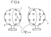
- FIG. 6 represents a variant embodiment in which the Groups 6 and 7 of microphones 3 belong to two distinct spheres 2.
- the invention provides a great improvement to the existing technique, providing a structural device simple way of determining the location of a source of noise and of measure the intensity, including inside a passenger compartment by distinguishing waves that arrive in front of or behind the antenna formed by different microphones, and by providing an improved signal processing mode still the conditions of location of a source of noise.
Abstract
Description
La présente invention a pour objet un système de mesure acoustique permettant de localiser des sources de bruit et d'en mesurer l'intensité.The present invention relates to a measuring system acoustics to locate noise sources and to measure them the intensity.
Le confort acoustique à l'intérieur d'une enceinte, et notamment d'un habitacle de véhicule, tel que véhicule automobile ou avion, est devenu un enjeu concurrenciel. Pour l'optimiser, il est nécessaire de connaítre l'importance du rayonnement sonore des différents panneaux de l'habitacle, tels que vitre ou hublot, paroi habillée... pour réaliser des traitements d'isolation acoustique là où cela est nécessaire. A cet effet, il convient de disposer de moyens permettant de localiser les sources de bruit, ainsi que l'intensité sonore de telles sources.The acoustic comfort inside an enclosure, and in particular of a vehicle interior, such as a motor vehicle or airplane, has become a competitive issue. To optimize it, it is necessary to know the importance of the sound radiation of the various panels of the passenger compartment, such as window or porthole, dressed wall ... to carry out treatments sound insulation where necessary. For this purpose, it is necessary to have means for locating sources of noise, as well as the loudness of such sources.
Un dispositif connu comprend plusieurs microphones omnidirectionnels, par exemple au nombre de 24, disposés sur un plan. Le plan sur lequel sont situés les microphones, est orienté sensiblement perpendiculairement à la direction présumée de la source de bruit. Les microphones mesurent la pression acoustique résultant de l'émission de bruit, et fournissent chacun un signal à un dispositif de traitement. Ce dispositif de traitement permet d'obtenir un hologramme des sources de bruit.A known device includes several microphones omnidirectional, for example the number of 24, arranged on a plane. The plane on which the microphones are located, is oriented substantially perpendicular to the presumed direction of the noise source. The microphones measure the sound pressure resulting from noise emission, and each provide a signal to a processing device. This device processing provides a hologram of noise sources.
L'hologramme des sources de bruit est obtenu en effectuant des calculs en différents points, les microphones mesurant la pression acoustique pour chacun des points, en tenant compte du déphasage des distances des différents microphones vis-à-vis des différents points de mesure.The hologram of noise sources is obtained by performing calculations at different points, the microphones measuring the sound pressure for each of the points, taking into account the phase shift of the distances of different microphones vis-à-vis the different measuring points.
Si ces dispositifs conviennent pour des mesures de bruit extérieurs, par exemple pour mesure le bruit d'un moteur au banc, ils sont pris en défaut dès qu'ils sont placés à l'intérieur d'un habitacle, car ils ne savent pas distinguer les ondes qui arrivent devant ou derrière l'antenne constituée par l'ensemble des microphones.If these devices are suitable for external noise measurements, for example to measure the sound of a motor on the bench, they are taken in default as soon as they are placed inside a cockpit because they do not know distinguish the waves that arrive in front of or behind the antenna formed by all the microphones.
L'hologramme des sources de bruit est obtenu en effectuant des calculs en différents points, les microphones mesurant la pression acoustique pour chacun des points, en tenant compte du déphasage des distances des différents microphones vis-à-vis des différents points de mesure.The hologram of noise sources is obtained by performing calculations at different points, the microphones measuring the sound pressure for each of the points, taking into account the phase shift of the distances of different microphones vis-à-vis the different measuring points.
Le problème technique à la base de l'invention est de fournir un système qui permette la localisation de façon précise et simple de sources de bruit à l'intérieur d'une enceinte.The technical problem underlying the invention is to provide a system which allows the precise and simple localization of sources of noise inside an enclosure.
A cet effet, le système qu'elle concerne comprend une pluralité de microphones orientés suivant plusieurs directions et montés dans un support de façon que chacun affleure une surface rigide, les différents microphones étant reliés à un dispositif de traitement du signal.For this purpose, the system it concerns comprises a plurality of microphones oriented in several directions and mounted in a support so that everyone is flush with a rigid surface, the different microphones being connected to a signal processing device.
Chaque microphone "voit" surtout les sources de bruit placées en regard, le corps rigide jouant le rôle d'écran pour les sources de bruit placées derrière le corps rigide, par rapport au microphone considéré.Each microphone "sees" especially the sources of noise placed in look, rigid body acting as screen for noise sources placed behind the rigid body, relative to the microphone considered.
Pour chaque point de calcul, il faut tenir compte du déphasage entre les différents microphones dû non seulement à la distance entre les différents microphones et le point de calcul, mais aussi à la présence du corps rigide, les ondes acoustiques ne traversant pas la surface rigide, mais contournant celle-ci. Il en résulte une augmentation du temps de parcours de l'onde acoustique, pour les microphones situés derrière le corps rigide, par rapport à la source de bruit, ce qui permet une augmentation du déphasage entre les différents microphones et par suite une augmentation de la résolution au niveau de la localisation de la source de bruit.For each calculation point, the phase shift must be taken into account between the different microphones due not only to the distance between the different microphones and the computation point, but also to the presence of the body rigid, acoustic waves not passing through the rigid surface, but bypassing this one. This results in an increase in travel time of the acoustic wave, for microphones located behind the rigid body, by relative to the noise source, which allows an increase in the phase shift between the different microphones and consequently an increase in the resolution at the location of the noise source.
Avantageusement, le support des microphones est revêtu d'un matériau absorbant, tel qu'une mousse cellulaire.Advantageously, the support of the microphones is coated with a absorbent material, such as cellular foam.
Suivant une forme d'exécution de ce système le support des microphones est constitué par une sphère.According to one embodiment of this system the support of microphones is constituted by a sphere.
Les différents microphones sont répartis sur la surface de la sphère. La sphère présente l'avantage qu'il s'agit d'une forme naturelle dont le comportement est facile à modéliser. Pour une position de source donnée, on peut calculer, pour chaque fréquence, le module et la phase de la pression acoustique mesurée par chaque microphone.The different microphones are distributed on the surface of the sphere. The sphere has the advantage that it is a natural form whose behavior is easy to model. For a given source position, we can calculate, for each frequency, the module and the phase of the pressure acoustic measured by each microphone.
Suivant une autre forme d'exécution de ce système, le support des microphones est constitué par deux disques parallèles reliés entre eux par une portion de surface torique, les microphones étant placés dans les disques.According to another embodiment of this system, the support of microphones consists of two parallel disks linked together by a portion of the toric surface, the microphones being placed in the disks.
Cette seconde forme d'exécution présente l'avantage de bien séparer les deux demi espaces.This second embodiment has the advantage of good separate the two half spaces.
Il est également possible d'envisager différentes formes du support rigide, celui-ci pouvant avoir par exemple la forme d'une ellipsoïde ou d'un parallélépipède.It is also possible to envisage different forms of support rigid, the latter may have for example the shape of an ellipsoid or a parallelepiped.
Le système de mesure selon l'invention consiste pour chaque groupe de microphones, à effectuer un traitement des signaux issus de ces microphones, pour fournir un hologramme des sources de bruit, c'est-à-dire une répartition des pressions ou intensités acoustiques en différents points d'une même surface. The measuring system according to the invention consists for each group of microphones, to perform a signal processing from these microphones, to provide a hologram of the sources of noise, i.e. a distribution of the pressures or acoustic intensities in different points of the same surface.
Avantageusement, le système selon l'invention consiste, avant réalisation d'une mesure, à répartir un certain nombre de microphones appartenant à un seul ou à deux supports, en deux groupes.Advantageously, the system according to the invention consists, before performing a measurement, to divide a certain number of microphones belonging to one or two supports, in two groups.
Cette répartition d'un certain nombre de microphones appartenant à un seul ou à deux supports, en deux groupes, permet d'effectuer pour les deux groupes de microphones un traitement différentiel des signaux issus des différents microphones des deux groupes.This distribution of a number of microphones belonging to one or two supports, in two groups, allows to carry out for the two groups of microphones a differential treatment of the signals from the different microphones of the two groups.
Ce traitement différentiel peut représenter le fonctionnement de l'oreille humaine.This differential treatment may represent the functioning of the human ear.
Suivant un premier mode de mise en oeuvre, ce système consiste à effectuer un traitement de focalisation pour chaque groupe de microphones en chaque point où l'on souhaite savoir s'il existe une source de bruit, puis à effectuer pour chaque point de calcul la différence entre les signaux focalisés des deux groupes, cette différence étant nulle lorsque le point de calcul correspond à l'emplacement de la source de bruit.According to a first mode of implementation, this system consists of perform focus processing for each group of microphones in every point where we want to know if there is a source of noise, then to perform for each calculation point the difference between the focused signals of the two groups, this difference being zero when the calculation point corresponds to the location of the noise source.
Suivant un second mode de mise en oeuvre, ce système consiste à effectuer un traitement de focalisation pour un groupe de microphones en différents points, situés du côté de ce groupe, en vue de déterminer l'existence de sources de bruit en ces différents points, et à effectuer, pour l'autre groupe de microphones un traitement de focalisation en des points opposés des premiers, puis à effectuer pour chaque groupe de deux points la différence entre les signaux focalisés des deux groupes, cette différence étant maximale lorsque le point de calcul correspond à l'emplacement de la source de bruit.According to a second mode of implementation, this system consists of perform focus processing for a group of microphones in different points, located on the side of this group, in order to determine the existence of noise sources in these different points, and to perform, for the other group of microphones focusing treatment at opposite points of first, then to perform for each group of two points the difference between the focused signals of the two groups, this difference being maximum when the calculation point corresponds to the location of the noise source.
De toute façon l'invention sera bien comprise à l'aide de la
description qui suit, en référence au dessin schématique annexé, représentant,
à titre d'exemples non limitatifs, plusieurs formes d'exécution de ce système.
La figure 1 représente une sphère 2 réalisée en matériau rigide, et
dont la surface extérieure peut être revêtue d'un matériau amortissant, tel que
de la mousse, ou peut être perforée. A l'intérieur de la sphère 2 sont montés
24 microphones 3, qui affleurent chacun la surface de la sphère 2.FIG. 1 represents a
Les figures 2 et 3 représentent une variante d'exécution de ce
système dans laquelle le corps rigide possède une forme différente, et est
constitué par deux disques plans 4 reliés entre eux par une portion de tore 5.
Comme montré à la figure 3, les microphones 3 affleurent les surfaces des
deux disques. Cette réalisation a l'avantage de bien séparer les deux demi
espaces.Figures 2 and 3 show an alternative embodiment of this
system in which the rigid body has a different shape, and is
consisting of two flat disks 4 interconnected by a
Les figures 4 et 5 représentent le dispositif de figure 1, c'est-à-dire
une sphère 2 équipée d'un certain nombre de microphones, en l'occurrence 24.
Certains microphones sont associés pour former un groupe 6, alors que
d'autres microphones sont associés pour former un groupe 7. Il est à noter que
les groupes 6 et 7 ne contiennent pas nécessairement tous les microphones de
la sphère 2. Il faut également remarquer que ce groupement est un
groupement virtuel et non pas physique, ce groupement étant réalisé au niveau
du traitement des signaux reçus par les différents microphones des deux
groupes 6 et 7.Figures 4 and 5 show the device of Figure 1, that is to say
a
Les figures 4 et 5 représentent la mise en oeuvre d'un traitement dit différentiel. A cet effet, le traitement permet d'estimer la position de la source de bruit maximal. Pour chaque point où l'on cherche à savoir s'il y a une source de bruit, on doit calculer un estimateur différentiel de la façon suivante. Il est procédé tout d'abord à un traitement de focalisation pour un même point de calcul C pour les deux groupes 6 et 7 de microphones. On calcule la fonction différence des deux résultats des groupes de microphones. Ce calcul est répété pour tous les points où l'on souhaite savoir s'il y a une source. Dans la forme d'exécution représentée à la figure 4, la focalisation s'effectue sur le même point C pour les deux groupes 6 et 7, et la fonction différence est minimale, lorsque le point de calcul C est situé à la position de la source de bruit.Figures 4 and 5 show the implementation of a treatment said differential. For this purpose, the treatment makes it possible to estimate the position of the source maximum noise. For each point where we want to know if there is a source of noise, a differential estimator must be calculated as follows. It is first of all a focusing treatment for the same point of C calculation for both groups 6 and 7 of microphones. We calculate the function difference of the two results of the groups of microphones. This calculation is repeated for all the points where we want to know if there is a source. In the embodiment shown in FIG. 4, the focus is on the same point C for both groups 6 and 7, and the difference function is when the calculation point C is located at the position of the source of the noise.
La figure 5 représente une variante d'exécution dans laquelle les mêmes éléments sont désignés par les mêmes références que précédemment. Dans ce cas, il est effectué un traitement de focalisation pour le groupe 6 de microphones, en un point P1 qui est le point dont on recherche s'il correspond à la source de bruit, tandis que la focalisation pour les microphones du groupe 7 est réalisée en un point P2 situé du côté opposé au point P1. On calcule la fonction différence entre les deux résultats de focalisation. Dans cette seconde solution, la fonction différence est maximale lorsque le point de calcul P1 est situé à la position de la source réelle de bruit.FIG. 5 represents a variant embodiment in which the same elements are designated by the same references as before. In this case, a focusing treatment is performed for group 6 of microphones, at a point P1 which is the point we are looking for if it corresponds at the source of noise, while the focus for the microphones of the group 7 is made at a point P2 located on the side opposite the point P1. We calculates the difference function between the two focusing results. In this second solution, the difference function is maximum when the point of P1 calculation is located at the position of the actual source of noise.
La figure 6 représente une variante d'exécution dans laquelle les
groupes 6 et 7 de microphones 3 appartiennent à deux sphères 2 distinctes.FIG. 6 represents a variant embodiment in which the
Groups 6 and 7 of
Comme il ressort de ce qui précède, l'invention apporte une grande amélioration à la technique existante, en fournissant un dispositif de structure simple permettant de déterminer la localisation d'une source de bruit et d'en mesurer l'intensité, y compris à l'intérieur d'un habitacle en distinguant les ondes qui arrivent devant ou derrière l'antenne formée par différents microphones, et en fournissant un mode de traitement des signaux améliorant encore les conditions de localisation d'une source de bruit.As is apparent from the foregoing, the invention provides a great improvement to the existing technique, providing a structural device simple way of determining the location of a source of noise and of measure the intensity, including inside a passenger compartment by distinguishing waves that arrive in front of or behind the antenna formed by different microphones, and by providing an improved signal processing mode still the conditions of location of a source of noise.
Comme il va de soi l'invention ne se limite pas aux seules formes d'exécution de ce système, décrites ci-dessus à titre d'exemple, elle en embrasse au contraire toutes les variantes. C'est ainsi notamment que le support rigide des microphones pourrait avoir une forme différente, par exemple une forme parallélépipédique, ou encore que le traitement des signaux pourrait ne pas comporter de traitement différentiel, mais la simple réalisation d'un hologramme de façon connue en soi, sans que l'on sorte pour autant du cadre de l'invention.It goes without saying that invention is not limited to forms implementation of this system, described above as an example, it on the contrary, embraces all variants. This is particularly the case rigid support of the microphones could have a different shape, by example a parallelepipedic form, or that the treatment of signals might not be differential, but the simple making a hologram in a manner known per se, without going out for as much of the scope of the invention.
Claims (8)
Applications Claiming Priority (2)
| Application Number | Priority Date | Filing Date | Title |
|---|---|---|---|
| FR0400202 | 2004-01-09 | ||
| FR0400202A FR2865040B1 (en) | 2004-01-09 | 2004-01-09 | ACOUSTIC MEASUREMENT SYSTEM FOR LOCATING NOISE SOURCES |
Publications (2)
| Publication Number | Publication Date |
|---|---|
| EP1557688A1 true EP1557688A1 (en) | 2005-07-27 |
| EP1557688B1 EP1557688B1 (en) | 2009-04-08 |
Family
ID=34630641
Family Applications (1)
| Application Number | Title | Priority Date | Filing Date |
|---|---|---|---|
| EP05356001A Not-in-force EP1557688B1 (en) | 2004-01-09 | 2005-01-03 | Acoustic measurement system for locating sources of noise |
Country Status (6)
| Country | Link |
|---|---|
| US (1) | US7817804B2 (en) |
| EP (1) | EP1557688B1 (en) |
| AT (1) | ATE428121T1 (en) |
| DE (1) | DE602005013708D1 (en) |
| DK (1) | DK1557688T3 (en) |
| FR (1) | FR2865040B1 (en) |
Cited By (3)
| Publication number | Priority date | Publication date | Assignee | Title |
|---|---|---|---|---|
| EP1840589A1 (en) * | 2006-03-29 | 2007-10-03 | Microdb | Device for acoustic location and intensity measurement |
| EP2485062A2 (en) | 2011-02-04 | 2012-08-08 | Microdb | Acoustic location device |
| CN104571492A (en) * | 2014-10-10 | 2015-04-29 | 上海大学 | Position distribution method of spherical surface sound source in virtual reality sound rendering |
Families Citing this family (8)
| Publication number | Priority date | Publication date | Assignee | Title |
|---|---|---|---|---|
| EP1867206B1 (en) * | 2005-03-16 | 2016-05-11 | James Cox | Microphone array and digital signal processing system |
| FR2896314B1 (en) * | 2006-01-18 | 2008-02-22 | Microdb Sa | DEVICE FOR LOCATING ACOUSTIC SOURCES AND MEASURING THEIR INTENSITY |
| WO2008042884A1 (en) * | 2006-10-02 | 2008-04-10 | Wayne State University | Locating arbitrary noise sources |
| SE534042C2 (en) * | 2009-08-19 | 2011-04-12 | Scania Cv Ab | Method and apparatus for simulating acoustic emissions from an engine |
| GB201321852D0 (en) * | 2013-12-10 | 2014-01-22 | Thales Holdings Uk Plc | Acoustic Detector |
| US10337757B2 (en) * | 2016-08-31 | 2019-07-02 | The Boeing Company | In-duct acoustic measuring apparatus and method |
| NO20211439A1 (en) * | 2021-11-26 | 2023-05-29 | Momentum Tech As | Noise mapping device |
| CN115027675B (en) * | 2022-06-21 | 2023-05-19 | 江汉大学 | Explosion field noise measuring device based on unmanned aerial vehicle platform |
Citations (4)
| Publication number | Priority date | Publication date | Assignee | Title |
|---|---|---|---|---|
| US4332979A (en) * | 1978-12-19 | 1982-06-01 | Fischer Mark L | Electronic environmental acoustic simulator |
| JPH0472525A (en) | 1990-07-13 | 1992-03-06 | Nippon Telegr & Teleph Corp <Ntt> | Sound source direction distinguishing sensor |
| US6310832B1 (en) * | 1982-11-17 | 2001-10-30 | Raytheon Company | Interpolated beamforming tracker |
| US20030147539A1 (en) * | 2002-01-11 | 2003-08-07 | Mh Acoustics, Llc, A Delaware Corporation | Audio system based on at least second-order eigenbeams |
Family Cites Families (4)
| Publication number | Priority date | Publication date | Assignee | Title |
|---|---|---|---|---|
| JP3789685B2 (en) * | 1999-07-02 | 2006-06-28 | 富士通株式会社 | Microphone array device |
| JP2001166025A (en) * | 1999-12-14 | 2001-06-22 | Matsushita Electric Ind Co Ltd | Sound source direction estimating method, sound collection method and device |
| JP4722347B2 (en) * | 2000-10-02 | 2011-07-13 | 中部電力株式会社 | Sound source exploration system |
| US7248703B1 (en) * | 2001-06-26 | 2007-07-24 | Bbn Technologies Corp. | Systems and methods for adaptive noise cancellation |
-
2004
- 2004-01-09 FR FR0400202A patent/FR2865040B1/en not_active Expired - Fee Related
-
2005
- 2005-01-03 EP EP05356001A patent/EP1557688B1/en not_active Not-in-force
- 2005-01-03 DE DE602005013708T patent/DE602005013708D1/en active Active
- 2005-01-03 AT AT05356001T patent/ATE428121T1/en not_active IP Right Cessation
- 2005-01-03 DK DK05356001T patent/DK1557688T3/en active
- 2005-01-04 US US11/027,939 patent/US7817804B2/en not_active Expired - Fee Related
Patent Citations (4)
| Publication number | Priority date | Publication date | Assignee | Title |
|---|---|---|---|---|
| US4332979A (en) * | 1978-12-19 | 1982-06-01 | Fischer Mark L | Electronic environmental acoustic simulator |
| US6310832B1 (en) * | 1982-11-17 | 2001-10-30 | Raytheon Company | Interpolated beamforming tracker |
| JPH0472525A (en) | 1990-07-13 | 1992-03-06 | Nippon Telegr & Teleph Corp <Ntt> | Sound source direction distinguishing sensor |
| US20030147539A1 (en) * | 2002-01-11 | 2003-08-07 | Mh Acoustics, Llc, A Delaware Corporation | Audio system based on at least second-order eigenbeams |
Non-Patent Citations (4)
| Title |
|---|
| PATENT ABSTRACTS OF JAPAN vol. 0162, no. 76 (P - 1374) 19 June 1992 (1992-06-19) * |
| VAUCHER DE LA CROIX D ET AL: "HOLOGRAPHIE ACOUSTIQUE APPLIQUEE A DES MESURES INTERIEURES 3D EN HABITACLE", INGENIEURS DE L'AUTOMOBILE, RAIP. BOULOGNE, FR, no. 741, November 2000 (2000-11-01), pages 132 - 136,139, XP000987553, ISSN: 0020-1200 * |
| WILLIAMS E ET AL.: "A prototype spherical array for interior noise investigations", JOURNAL OF THE ACOUSTIC SOCIETY OF AMERICA, vol. 112, no. 5, pages 2 |
| WILLIAMS E ET AL: "A prototype spherical array for interior noise investigations", JOURNAL OF THE ACOUSTIC SOCIETY OF AMERICA. VOL. 112, NO. 5, PART 2, November 2002 (2002-11-01), pages 2348, XP002325567, Retrieved from the Internet <URL:http://scitation.aip.org/jasa/> [retrieved on 20050421] * |
Cited By (6)
| Publication number | Priority date | Publication date | Assignee | Title |
|---|---|---|---|---|
| EP1840589A1 (en) * | 2006-03-29 | 2007-10-03 | Microdb | Device for acoustic location and intensity measurement |
| FR2899341A1 (en) * | 2006-03-29 | 2007-10-05 | Microdb Sa | DEVICE FOR ACOUSTIC LOCALIZATION AND MEASUREMENT OF THEIR INTENSITY |
| EP2485062A2 (en) | 2011-02-04 | 2012-08-08 | Microdb | Acoustic location device |
| US8923521B2 (en) | 2011-02-04 | 2014-12-30 | Microdb | Device for localizing acoustic sources and/or measuring their intensities |
| CN104571492A (en) * | 2014-10-10 | 2015-04-29 | 上海大学 | Position distribution method of spherical surface sound source in virtual reality sound rendering |
| CN104571492B (en) * | 2014-10-10 | 2017-12-05 | 上海大学 | A kind of virtual reality sound renders the position distribution method on middle spherical source surface |
Also Published As
| Publication number | Publication date |
|---|---|
| ATE428121T1 (en) | 2009-04-15 |
| US7817804B2 (en) | 2010-10-19 |
| DK1557688T3 (en) | 2009-08-03 |
| EP1557688B1 (en) | 2009-04-08 |
| FR2865040A1 (en) | 2005-07-15 |
| US20050163330A1 (en) | 2005-07-28 |
| FR2865040B1 (en) | 2006-05-05 |
| DE602005013708D1 (en) | 2009-05-20 |
Similar Documents
| Publication | Publication Date | Title |
|---|---|---|
| EP0904535B1 (en) | Method and device for detecting and locating a reverberating source of sound | |
| EP1557688B1 (en) | Acoustic measurement system for locating sources of noise | |
| CA2318378C (en) | Multielement ultrasonic contact transducer | |
| US10024957B2 (en) | Adaptive beamformer for sonar imaging | |
| EP0150634B1 (en) | Transducer for ultrasonic echography provided with an array of elements forming a convex surface | |
| US20060133211A1 (en) | Method and apparatus for acoustic source tracking using a horizontal line array | |
| CA2786411A1 (en) | Method and device for acquiring marine seismic data | |
| EP0543445A1 (en) | Examination device for media by means of ultrasonic echography | |
| Dall'Osto et al. | Measurement of acoustic particle motion in shallow water and its application to geoacoustic inversion | |
| EP0733408B1 (en) | Ultrasonic sensor and detection method using such a sensor | |
| Gerstoft et al. | Adaptive beamforming of a towed array during a turn | |
| EP1811346B1 (en) | Device for the localization and the measurement of the intensity of acoustic sources | |
| EP0015852B1 (en) | Device for measuring the total or the directional power emitted by an acoustical source | |
| FR2845510A1 (en) | Acoustic level measurement in room or vehicle uses ultrasound system for precise location of microphone, enabling acoustic levels to be plotted | |
| EP0093057A1 (en) | Adaptive filtering apparatus for rejecting reverberation in an active sonar | |
| CA2652564A1 (en) | Improved frontal sonar | |
| FR2590679A1 (en) | METHOD FOR PASSIVELY DETERMINING REPAIR DATA OF A VEHICLE | |
| EP0402968B1 (en) | Device for measuring the speed of blood-flow | |
| FR3090965A1 (en) | Two-dimensional Fourier transform ultrasound imaging method, computer program and corresponding ultrasound probing device | |
| FR2899341A1 (en) | DEVICE FOR ACOUSTIC LOCALIZATION AND MEASUREMENT OF THEIR INTENSITY | |
| Gerstoft et al. | Phenomenological and global optimization inversion | |
| FR2533790A1 (en) | MICROPHONE DEVICE | |
| Gebbie et al. | Extracting the Rayleigh reflection coefficient from the passive fathometer | |
| EP4197450A1 (en) | Device and method for assessing cardiovascular activity using ultrasound | |
| WO2021023933A1 (en) | Method and system for non-invasively characterising a heterogeneous medium using ultrasound |
Legal Events
| Date | Code | Title | Description |
|---|---|---|---|
| PUAI | Public reference made under article 153(3) epc to a published international application that has entered the european phase |
Free format text: ORIGINAL CODE: 0009012 |
|
| AK | Designated contracting states |
Kind code of ref document: A1 Designated state(s): AT BE BG CH CY CZ DE DK EE ES FI FR GB GR HU IE IS IT LI LT LU MC NL PL PT RO SE SI SK TR |
|
| AX | Request for extension of the european patent |
Extension state: AL BA HR LV MK YU |
|
| 17P | Request for examination filed |
Effective date: 20051219 |
|
| AKX | Designation fees paid |
Designated state(s): AT BE BG CH CY CZ DE DK EE ES FI FR GB GR HU IE IS IT LI LT LU MC NL PL PT RO SE SI SK TR |
|
| GRAP | Despatch of communication of intention to grant a patent |
Free format text: ORIGINAL CODE: EPIDOSNIGR1 |
|
| GRAS | Grant fee paid |
Free format text: ORIGINAL CODE: EPIDOSNIGR3 |
|
| GRAA | (expected) grant |
Free format text: ORIGINAL CODE: 0009210 |
|
| AK | Designated contracting states |
Kind code of ref document: B1 Designated state(s): AT BE BG CH CY CZ DE DK EE ES FI FR GB GR HU IE IS IT LI LT LU MC NL PL PT RO SE SI SK TR |
|
| REG | Reference to a national code |
Ref country code: GB Ref legal event code: FG4D Free format text: NOT ENGLISH |
|
| REG | Reference to a national code |
Ref country code: CH Ref legal event code: EP |
|
| REG | Reference to a national code |
Ref country code: IE Ref legal event code: FG4D |
|
| REF | Corresponds to: |
Ref document number: 602005013708 Country of ref document: DE Date of ref document: 20090520 Kind code of ref document: P |
|
| PG25 | Lapsed in a contracting state [announced via postgrant information from national office to epo] |
Ref country code: SI Free format text: LAPSE BECAUSE OF FAILURE TO SUBMIT A TRANSLATION OF THE DESCRIPTION OR TO PAY THE FEE WITHIN THE PRESCRIBED TIME-LIMIT Effective date: 20090408 |
|
| REG | Reference to a national code |
Ref country code: DK Ref legal event code: T3 |
|
| REG | Reference to a national code |
Ref country code: SE Ref legal event code: TRGR |
|
| NLV1 | Nl: lapsed or annulled due to failure to fulfill the requirements of art. 29p and 29m of the patents act | ||
| REG | Reference to a national code |
Ref country code: IE Ref legal event code: FD4D |
|
| PG25 | Lapsed in a contracting state [announced via postgrant information from national office to epo] |
Ref country code: LT Free format text: LAPSE BECAUSE OF FAILURE TO SUBMIT A TRANSLATION OF THE DESCRIPTION OR TO PAY THE FEE WITHIN THE PRESCRIBED TIME-LIMIT Effective date: 20090408 Ref country code: FI Free format text: LAPSE BECAUSE OF FAILURE TO SUBMIT A TRANSLATION OF THE DESCRIPTION OR TO PAY THE FEE WITHIN THE PRESCRIBED TIME-LIMIT Effective date: 20090408 Ref country code: ES Free format text: LAPSE BECAUSE OF FAILURE TO SUBMIT A TRANSLATION OF THE DESCRIPTION OR TO PAY THE FEE WITHIN THE PRESCRIBED TIME-LIMIT Effective date: 20090719 Ref country code: AT Free format text: LAPSE BECAUSE OF FAILURE TO SUBMIT A TRANSLATION OF THE DESCRIPTION OR TO PAY THE FEE WITHIN THE PRESCRIBED TIME-LIMIT Effective date: 20090408 Ref country code: PT Free format text: LAPSE BECAUSE OF FAILURE TO SUBMIT A TRANSLATION OF THE DESCRIPTION OR TO PAY THE FEE WITHIN THE PRESCRIBED TIME-LIMIT Effective date: 20090908 |
|
| PG25 | Lapsed in a contracting state [announced via postgrant information from national office to epo] |
Ref country code: PL Free format text: LAPSE BECAUSE OF FAILURE TO SUBMIT A TRANSLATION OF THE DESCRIPTION OR TO PAY THE FEE WITHIN THE PRESCRIBED TIME-LIMIT Effective date: 20090408 Ref country code: IS Free format text: LAPSE BECAUSE OF FAILURE TO SUBMIT A TRANSLATION OF THE DESCRIPTION OR TO PAY THE FEE WITHIN THE PRESCRIBED TIME-LIMIT Effective date: 20090808 Ref country code: NL Free format text: LAPSE BECAUSE OF FAILURE TO SUBMIT A TRANSLATION OF THE DESCRIPTION OR TO PAY THE FEE WITHIN THE PRESCRIBED TIME-LIMIT Effective date: 20090408 |
|
| PG25 | Lapsed in a contracting state [announced via postgrant information from national office to epo] |
Ref country code: EE Free format text: LAPSE BECAUSE OF FAILURE TO SUBMIT A TRANSLATION OF THE DESCRIPTION OR TO PAY THE FEE WITHIN THE PRESCRIBED TIME-LIMIT Effective date: 20090408 Ref country code: IE Free format text: LAPSE BECAUSE OF FAILURE TO SUBMIT A TRANSLATION OF THE DESCRIPTION OR TO PAY THE FEE WITHIN THE PRESCRIBED TIME-LIMIT Effective date: 20090408 Ref country code: CZ Free format text: LAPSE BECAUSE OF FAILURE TO SUBMIT A TRANSLATION OF THE DESCRIPTION OR TO PAY THE FEE WITHIN THE PRESCRIBED TIME-LIMIT Effective date: 20090408 Ref country code: RO Free format text: LAPSE BECAUSE OF FAILURE TO SUBMIT A TRANSLATION OF THE DESCRIPTION OR TO PAY THE FEE WITHIN THE PRESCRIBED TIME-LIMIT Effective date: 20090408 |
|
| PLBE | No opposition filed within time limit |
Free format text: ORIGINAL CODE: 0009261 |
|
| STAA | Information on the status of an ep patent application or granted ep patent |
Free format text: STATUS: NO OPPOSITION FILED WITHIN TIME LIMIT |
|
| PG25 | Lapsed in a contracting state [announced via postgrant information from national office to epo] |
Ref country code: SK Free format text: LAPSE BECAUSE OF FAILURE TO SUBMIT A TRANSLATION OF THE DESCRIPTION OR TO PAY THE FEE WITHIN THE PRESCRIBED TIME-LIMIT Effective date: 20090408 |
|
| 26N | No opposition filed |
Effective date: 20100111 |
|
| PG25 | Lapsed in a contracting state [announced via postgrant information from national office to epo] |
Ref country code: BG Free format text: LAPSE BECAUSE OF FAILURE TO SUBMIT A TRANSLATION OF THE DESCRIPTION OR TO PAY THE FEE WITHIN THE PRESCRIBED TIME-LIMIT Effective date: 20090708 |
|
| BERE | Be: lapsed |
Owner name: AIRBUS FRANCE Effective date: 20100131 Owner name: MICRODB Effective date: 20100131 |
|
| PG25 | Lapsed in a contracting state [announced via postgrant information from national office to epo] |
Ref country code: MC Free format text: LAPSE BECAUSE OF NON-PAYMENT OF DUE FEES Effective date: 20100131 |
|
| REG | Reference to a national code |
Ref country code: CH Ref legal event code: PL |
|
| PG25 | Lapsed in a contracting state [announced via postgrant information from national office to epo] |
Ref country code: GR Free format text: LAPSE BECAUSE OF FAILURE TO SUBMIT A TRANSLATION OF THE DESCRIPTION OR TO PAY THE FEE WITHIN THE PRESCRIBED TIME-LIMIT Effective date: 20090709 Ref country code: LI Free format text: LAPSE BECAUSE OF NON-PAYMENT OF DUE FEES Effective date: 20100131 Ref country code: CH Free format text: LAPSE BECAUSE OF NON-PAYMENT OF DUE FEES Effective date: 20100131 |
|
| PG25 | Lapsed in a contracting state [announced via postgrant information from national office to epo] |
Ref country code: BE Free format text: LAPSE BECAUSE OF NON-PAYMENT OF DUE FEES Effective date: 20100131 |
|
| REG | Reference to a national code |
Ref country code: GB Ref legal event code: 732E Free format text: REGISTERED BETWEEN 20110721 AND 20110727 |
|
| REG | Reference to a national code |
Ref country code: DE Ref legal event code: R082 Ref document number: 602005013708 Country of ref document: DE Representative=s name: PATENTANWAELTE MAGENBAUER & KOLLEGEN, DE |
|
| REG | Reference to a national code |
Ref country code: FR Ref legal event code: CD Owner name: AIRBUS OPERATIONS, FR Effective date: 20120313 Ref country code: FR Ref legal event code: CA Effective date: 20120313 Ref country code: FR Ref legal event code: CJ Effective date: 20120313 |
|
| REG | Reference to a national code |
Ref country code: DE Ref legal event code: R082 Ref document number: 602005013708 Country of ref document: DE Representative=s name: PATENTANWAELTE MAGENBAUER & KOLLEGEN PARTNERSC, DE Effective date: 20120326 Ref country code: DE Ref legal event code: R081 Ref document number: 602005013708 Country of ref document: DE Owner name: AIRBUS OPERATIONS SAS, FR Free format text: FORMER OWNER: MICRODB, AIRBUS FRANCE, , FR Effective date: 20120326 Ref country code: DE Ref legal event code: R081 Ref document number: 602005013708 Country of ref document: DE Owner name: MICRODB, FR Free format text: FORMER OWNER: MICRODB, AIRBUS FRANCE, , FR Effective date: 20120326 Ref country code: DE Ref legal event code: R082 Ref document number: 602005013708 Country of ref document: DE Representative=s name: PATENTANWAELTE MAGENBAUER & KOLLEGEN, DE Effective date: 20120326 Ref country code: DE Ref legal event code: R081 Ref document number: 602005013708 Country of ref document: DE Owner name: MICRODB, FR Free format text: FORMER OWNERS: MICRODB, ECULLY, FR; AIRBUS FRANCE, TOULOUSE, FR Effective date: 20120326 Ref country code: DE Ref legal event code: R081 Ref document number: 602005013708 Country of ref document: DE Owner name: AIRBUS OPERATIONS SAS, FR Free format text: FORMER OWNERS: MICRODB, ECULLY, FR; AIRBUS FRANCE, TOULOUSE, FR Effective date: 20120326 |
|
| PG25 | Lapsed in a contracting state [announced via postgrant information from national office to epo] |
Ref country code: CY Free format text: LAPSE BECAUSE OF FAILURE TO SUBMIT A TRANSLATION OF THE DESCRIPTION OR TO PAY THE FEE WITHIN THE PRESCRIBED TIME-LIMIT Effective date: 20090408 |
|
| PG25 | Lapsed in a contracting state [announced via postgrant information from national office to epo] |
Ref country code: HU Free format text: LAPSE BECAUSE OF FAILURE TO SUBMIT A TRANSLATION OF THE DESCRIPTION OR TO PAY THE FEE WITHIN THE PRESCRIBED TIME-LIMIT Effective date: 20091009 Ref country code: LU Free format text: LAPSE BECAUSE OF NON-PAYMENT OF DUE FEES Effective date: 20100103 |
|
| PG25 | Lapsed in a contracting state [announced via postgrant information from national office to epo] |
Ref country code: TR Free format text: LAPSE BECAUSE OF FAILURE TO SUBMIT A TRANSLATION OF THE DESCRIPTION OR TO PAY THE FEE WITHIN THE PRESCRIBED TIME-LIMIT Effective date: 20090408 |
|
| REG | Reference to a national code |
Ref country code: FR Ref legal event code: TP Owner name: AIRBUS HOLDING, FR Effective date: 20130322 |
|
| REG | Reference to a national code |
Ref country code: FR Ref legal event code: PLFP Year of fee payment: 12 |
|
| REG | Reference to a national code |
Ref country code: FR Ref legal event code: PLFP Year of fee payment: 13 |
|
| REG | Reference to a national code |
Ref country code: FR Ref legal event code: PLFP Year of fee payment: 14 |
|
| PGFP | Annual fee paid to national office [announced via postgrant information from national office to epo] |
Ref country code: GB Payment date: 20180119 Year of fee payment: 14 Ref country code: DE Payment date: 20180122 Year of fee payment: 14 Ref country code: DK Payment date: 20180119 Year of fee payment: 14 |
|
| PGFP | Annual fee paid to national office [announced via postgrant information from national office to epo] |
Ref country code: IT Payment date: 20180129 Year of fee payment: 14 Ref country code: SE Payment date: 20180119 Year of fee payment: 14 Ref country code: FR Payment date: 20180119 Year of fee payment: 14 |
|
| REG | Reference to a national code |
Ref country code: DE Ref legal event code: R119 Ref document number: 602005013708 Country of ref document: DE |
|
| REG | Reference to a national code |
Ref country code: DK Ref legal event code: EBP Effective date: 20190131 |
|
| GBPC | Gb: european patent ceased through non-payment of renewal fee |
Effective date: 20190103 |
|
| PG25 | Lapsed in a contracting state [announced via postgrant information from national office to epo] |
Ref country code: FR Free format text: LAPSE BECAUSE OF NON-PAYMENT OF DUE FEES Effective date: 20190131 Ref country code: DE Free format text: LAPSE BECAUSE OF NON-PAYMENT OF DUE FEES Effective date: 20190801 Ref country code: SE Free format text: LAPSE BECAUSE OF NON-PAYMENT OF DUE FEES Effective date: 20190104 |
|
| PG25 | Lapsed in a contracting state [announced via postgrant information from national office to epo] |
Ref country code: GB Free format text: LAPSE BECAUSE OF NON-PAYMENT OF DUE FEES Effective date: 20190103 |
|
| PG25 | Lapsed in a contracting state [announced via postgrant information from national office to epo] |
Ref country code: DK Free format text: LAPSE BECAUSE OF NON-PAYMENT OF DUE FEES Effective date: 20190131 |
|
| PG25 | Lapsed in a contracting state [announced via postgrant information from national office to epo] |
Ref country code: IT Free format text: LAPSE BECAUSE OF NON-PAYMENT OF DUE FEES Effective date: 20190103 |