EP1557602B1 - Conduite thermiquement isolée - Google Patents
Conduite thermiquement isolée Download PDFInfo
- Publication number
- EP1557602B1 EP1557602B1 EP04293045A EP04293045A EP1557602B1 EP 1557602 B1 EP1557602 B1 EP 1557602B1 EP 04293045 A EP04293045 A EP 04293045A EP 04293045 A EP04293045 A EP 04293045A EP 1557602 B1 EP1557602 B1 EP 1557602B1
- Authority
- EP
- European Patent Office
- Prior art keywords
- pipe
- pipeline according
- insulation layer
- thermal insulation
- pipeline
- Prior art date
- Legal status (The legal status is an assumption and is not a legal conclusion. Google has not performed a legal analysis and makes no representation as to the accuracy of the status listed.)
- Expired - Lifetime
Links
- 238000009413 insulation Methods 0.000 claims abstract description 111
- 239000000463 material Substances 0.000 claims abstract description 43
- 239000012530 fluid Substances 0.000 claims abstract description 8
- 230000001681 protective effect Effects 0.000 claims description 44
- 238000009434 installation Methods 0.000 claims description 16
- 230000008602 contraction Effects 0.000 claims description 14
- 238000011068 loading method Methods 0.000 claims description 14
- 239000007788 liquid Substances 0.000 claims description 11
- 239000002131 composite material Substances 0.000 claims description 10
- 239000011810 insulating material Substances 0.000 claims description 9
- 125000006850 spacer group Chemical group 0.000 claims description 9
- 239000000470 constituent Substances 0.000 claims description 6
- 239000013535 sea water Substances 0.000 claims description 6
- 229910045601 alloy Inorganic materials 0.000 claims description 4
- 239000000956 alloy Substances 0.000 claims description 4
- 230000003247 decreasing effect Effects 0.000 claims description 4
- 239000002952 polymeric resin Substances 0.000 claims description 2
- 229920003002 synthetic resin Polymers 0.000 claims description 2
- 230000008646 thermal stress Effects 0.000 claims description 2
- PXHVJJICTQNCMI-UHFFFAOYSA-N Nickel Chemical compound [Ni] PXHVJJICTQNCMI-UHFFFAOYSA-N 0.000 claims 2
- 230000000903 blocking effect Effects 0.000 claims 1
- 239000002086 nanomaterial Substances 0.000 claims 1
- 229910052759 nickel Inorganic materials 0.000 claims 1
- 239000010935 stainless steel Substances 0.000 abstract description 5
- 229910001220 stainless steel Inorganic materials 0.000 abstract description 4
- 239000007789 gas Substances 0.000 description 39
- 239000011248 coating agent Substances 0.000 description 15
- 238000000576 coating method Methods 0.000 description 15
- XLYOFNOQVPJJNP-UHFFFAOYSA-N water Substances O XLYOFNOQVPJJNP-UHFFFAOYSA-N 0.000 description 13
- 239000003949 liquefied natural gas Substances 0.000 description 10
- 239000013307 optical fiber Substances 0.000 description 10
- IJGRMHOSHXDMSA-UHFFFAOYSA-N Atomic nitrogen Chemical compound N#N IJGRMHOSHXDMSA-UHFFFAOYSA-N 0.000 description 7
- 229910001374 Invar Inorganic materials 0.000 description 6
- 229910000831 Steel Inorganic materials 0.000 description 6
- 230000000694 effects Effects 0.000 description 6
- 230000009545 invasion Effects 0.000 description 6
- VNWKTOKETHGBQD-UHFFFAOYSA-N methane Chemical compound C VNWKTOKETHGBQD-UHFFFAOYSA-N 0.000 description 6
- 238000000034 method Methods 0.000 description 6
- 239000010959 steel Substances 0.000 description 6
- 239000011324 bead Substances 0.000 description 5
- 238000005260 corrosion Methods 0.000 description 5
- 238000001514 detection method Methods 0.000 description 5
- 239000011261 inert gas Substances 0.000 description 5
- 230000002093 peripheral effect Effects 0.000 description 5
- 238000011084 recovery Methods 0.000 description 5
- 238000001816 cooling Methods 0.000 description 4
- 230000007797 corrosion Effects 0.000 description 4
- 238000001035 drying Methods 0.000 description 4
- 239000004744 fabric Substances 0.000 description 4
- 230000036961 partial effect Effects 0.000 description 4
- 238000007789 sealing Methods 0.000 description 4
- 239000004753 textile Substances 0.000 description 4
- 238000003466 welding Methods 0.000 description 4
- 230000008901 benefit Effects 0.000 description 3
- 238000010586 diagram Methods 0.000 description 3
- 238000002955 isolation Methods 0.000 description 3
- 238000004519 manufacturing process Methods 0.000 description 3
- 229910052757 nitrogen Inorganic materials 0.000 description 3
- 230000009467 reduction Effects 0.000 description 3
- 230000035939 shock Effects 0.000 description 3
- 238000004513 sizing Methods 0.000 description 3
- 238000003860 storage Methods 0.000 description 3
- 229910000990 Ni alloy Inorganic materials 0.000 description 2
- VYPSYNLAJGMNEJ-UHFFFAOYSA-N Silicium dioxide Chemical compound O=[Si]=O VYPSYNLAJGMNEJ-UHFFFAOYSA-N 0.000 description 2
- 239000004964 aerogel Substances 0.000 description 2
- 238000004873 anchoring Methods 0.000 description 2
- 229920006231 aramid fiber Polymers 0.000 description 2
- 230000004888 barrier function Effects 0.000 description 2
- 230000006378 damage Effects 0.000 description 2
- 239000002360 explosive Substances 0.000 description 2
- 238000011049 filling Methods 0.000 description 2
- 239000006260 foam Substances 0.000 description 2
- 239000011521 glass Substances 0.000 description 2
- 238000007654 immersion Methods 0.000 description 2
- 239000012212 insulator Substances 0.000 description 2
- 230000000670 limiting effect Effects 0.000 description 2
- 230000004807 localization Effects 0.000 description 2
- 230000007246 mechanism Effects 0.000 description 2
- 229910052751 metal Inorganic materials 0.000 description 2
- 239000002184 metal Substances 0.000 description 2
- 239000000203 mixture Substances 0.000 description 2
- 239000007783 nanoporous material Substances 0.000 description 2
- 230000002829 reductive effect Effects 0.000 description 2
- 239000002893 slag Substances 0.000 description 2
- 230000035882 stress Effects 0.000 description 2
- 229920000049 Carbon (fiber) Polymers 0.000 description 1
- 229920002430 Fibre-reinforced plastic Polymers 0.000 description 1
- 229920005830 Polyurethane Foam Polymers 0.000 description 1
- 241000183024 Populus tremula Species 0.000 description 1
- 230000002159 abnormal effect Effects 0.000 description 1
- 238000004026 adhesive bonding Methods 0.000 description 1
- 230000002411 adverse Effects 0.000 description 1
- PNEYBMLMFCGWSK-UHFFFAOYSA-N aluminium oxide Inorganic materials [O-2].[O-2].[O-2].[Al+3].[Al+3] PNEYBMLMFCGWSK-UHFFFAOYSA-N 0.000 description 1
- 238000010420 art technique Methods 0.000 description 1
- 230000015572 biosynthetic process Effects 0.000 description 1
- 229910052799 carbon Inorganic materials 0.000 description 1
- 239000004917 carbon fiber Substances 0.000 description 1
- 239000000969 carrier Substances 0.000 description 1
- 238000005266 casting Methods 0.000 description 1
- 239000003086 colorant Substances 0.000 description 1
- 230000007547 defect Effects 0.000 description 1
- 229910001873 dinitrogen Inorganic materials 0.000 description 1
- 239000013013 elastic material Substances 0.000 description 1
- 239000003822 epoxy resin Substances 0.000 description 1
- 230000001747 exhibiting effect Effects 0.000 description 1
- 239000011151 fibre-reinforced plastic Substances 0.000 description 1
- 239000011152 fibreglass Substances 0.000 description 1
- 239000011888 foil Substances 0.000 description 1
- 239000003365 glass fiber Substances 0.000 description 1
- 239000008187 granular material Substances 0.000 description 1
- WHJFNYXPKGDKBB-UHFFFAOYSA-N hafnium;methane Chemical compound C.[Hf] WHJFNYXPKGDKBB-UHFFFAOYSA-N 0.000 description 1
- 238000010438 heat treatment Methods 0.000 description 1
- 230000006872 improvement Effects 0.000 description 1
- 230000008595 infiltration Effects 0.000 description 1
- 238000001764 infiltration Methods 0.000 description 1
- 230000033001 locomotion Effects 0.000 description 1
- 230000035699 permeability Effects 0.000 description 1
- 239000003209 petroleum derivative Substances 0.000 description 1
- ISWSIDIOOBJBQZ-UHFFFAOYSA-N phenol group Chemical group C1(=CC=CC=C1)O ISWSIDIOOBJBQZ-UHFFFAOYSA-N 0.000 description 1
- 229920000647 polyepoxide Polymers 0.000 description 1
- 229920001225 polyester resin Polymers 0.000 description 1
- 239000004645 polyester resin Substances 0.000 description 1
- 229920000642 polymer Polymers 0.000 description 1
- 239000011496 polyurethane foam Substances 0.000 description 1
- 230000008569 process Effects 0.000 description 1
- 238000010926 purge Methods 0.000 description 1
- 229920005989 resin Polymers 0.000 description 1
- 239000011347 resin Substances 0.000 description 1
- 238000009420 retrofitting Methods 0.000 description 1
- 230000000630 rising effect Effects 0.000 description 1
- 230000035945 sensitivity Effects 0.000 description 1
- 238000007493 shaping process Methods 0.000 description 1
- 239000000377 silicon dioxide Substances 0.000 description 1
- 239000007787 solid Substances 0.000 description 1
- 239000011343 solid material Substances 0.000 description 1
- 229910001256 stainless steel alloy Inorganic materials 0.000 description 1
- 239000000725 suspension Substances 0.000 description 1
- 238000009834 vaporization Methods 0.000 description 1
- 230000008016 vaporization Effects 0.000 description 1
- 238000009423 ventilation Methods 0.000 description 1
- 238000011179 visual inspection Methods 0.000 description 1
Images


Classifications
-
- F—MECHANICAL ENGINEERING; LIGHTING; HEATING; WEAPONS; BLASTING
- F16—ENGINEERING ELEMENTS AND UNITS; GENERAL MEASURES FOR PRODUCING AND MAINTAINING EFFECTIVE FUNCTIONING OF MACHINES OR INSTALLATIONS; THERMAL INSULATION IN GENERAL
- F16L—PIPES; JOINTS OR FITTINGS FOR PIPES; SUPPORTS FOR PIPES, CABLES OR PROTECTIVE TUBING; MEANS FOR THERMAL INSULATION IN GENERAL
- F16L59/00—Thermal insulation in general
- F16L59/02—Shape or form of insulating materials, with or without coverings integral with the insulating materials
- F16L59/029—Shape or form of insulating materials, with or without coverings integral with the insulating materials layered
-
- B—PERFORMING OPERATIONS; TRANSPORTING
- B31—MAKING ARTICLES OF PAPER, CARDBOARD OR MATERIAL WORKED IN A MANNER ANALOGOUS TO PAPER; WORKING PAPER, CARDBOARD OR MATERIAL WORKED IN A MANNER ANALOGOUS TO PAPER
- B31D—MAKING ARTICLES OF PAPER, CARDBOARD OR MATERIAL WORKED IN A MANNER ANALOGOUS TO PAPER, NOT PROVIDED FOR IN SUBCLASSES B31B OR B31C
- B31D5/00—Multiple-step processes for making three-dimensional articles ; Making three-dimensional articles
- B31D5/02—Multiple-step processes for making three-dimensional articles ; Making three-dimensional articles including pressing
-
- B—PERFORMING OPERATIONS; TRANSPORTING
- B31—MAKING ARTICLES OF PAPER, CARDBOARD OR MATERIAL WORKED IN A MANNER ANALOGOUS TO PAPER; WORKING PAPER, CARDBOARD OR MATERIAL WORKED IN A MANNER ANALOGOUS TO PAPER
- B31F—MECHANICAL WORKING OR DEFORMATION OF PAPER, CARDBOARD OR MATERIAL WORKED IN A MANNER ANALOGOUS TO PAPER
- B31F1/00—Mechanical deformation without removing material, e.g. in combination with laminating
- B31F1/0077—Shaping by methods analogous to moulding, e.g. deep drawing techniques
Definitions
- the present invention relates to a thermally insulated pipe intended in particular for the transport of liquefied natural gas, in particular submarine, its use and a marine terminal comprising such a pipe.
- a thermally insulated pipe intended in particular for the transport of liquefied natural gas, in particular submarine, its use and a marine terminal comprising such a pipe.
- Such conduct is known for example from the document US4014369 .
- the pipe must necessarily include thermal insulation to prevent heating of the liquefied gas and thus limit its vaporization.
- the object of the invention is to propose a new thermally insulated pipe which has many qualities.
- the invention aims to provide a pipe with a high level of thermal insulation and operational safety.
- the double insulation layer makes it possible to minimize the amplitude of the thermal cycles undergone by the second pipe while maintaining a second insulation capable of thermally isolating the concrete ballast and the steel casing from a possible invasion of the first pipe. insulation by the liquid.
- the present invention provides an increased security of the installation.
- the present invention provides a particularly simple method of retrofitting the thermal expansion.
- the two pipes have these characteristics.
- At least one of said sealed pipes consists of a high-nickel alloy.
- These alloys such as for example the Invar, make it possible to obtain the mechanical characteristics above.
- the second sealed pipe is made of composite material based on a polymer resin.
- the use of such a material to produce the second sealed pipe generates a significant reduction in the manufacturing costs of the pipe.
- the composite materials may also be selected to have the above mechanical characteristics.
- the two pipes and the outer casing satisfy this criterion, which makes it possible to conduct a pipe possibly devoid of any system for compensating the thermal contraction.
- At least one of said pipes is provided with at least one thermal contraction compensation system.
- Such a system makes it possible to improve the recovery of the thermal effects.
- said thermal contraction compensation system is in the form of a sleeve comprising at least one radial corrugation.
- At least one element of the group consisting of the first pipe, the second pipe and the protective envelope is anchored at its ends to fixed stops ensuring the recovery of thermal stresses on said element.
- the ballast consists of a material capable of being cast in a liquid, powdery or granular form in the cylindrical volume between the second insulating layer and the protective envelope.
- said ballast comprises concrete inside of the protective envelope.
- the concrete is indeed easy to pour, the envelope serving as a mold.
- the concrete is then protected from the outside by the steel casing, giving the assembly good shock resistance and a perfect seal.
- a protective film is disposed between the concrete ballast and said secondary thermal insulation layer.
- the purpose of the protective film is to prevent the invasion of concrete slag into the secondary insulation layer during casting.
- said ballast comprises at least one hollow duct formed in the latter, which can be used for ventilation or drying.
- the hollow duct is disposed in the longitudinal direction and along the entire length of said duct.
- the hollow duct also makes it possible to evacuate the water exuded from the concrete during drying or to detect a possible intrusion of seawater. It also possibly makes it possible to circulate an inert gas.
- At least one of the thermal insulation layers is of material having a thermal conductivity of less than 20 ⁇ 10 -3 Wm -1 .K -1 at room temperature, preferably less than 16 ⁇ 10 -3 Wm -1 .K -1. at -160 ° C. Aerogels generally meet this criterion.
- the controlled industrial vacuum is no longer required to ensure satisfactory thermal insulation, which avoids the provision of depressurization equipment and a specific dimensioning of the pipes necessary for the establishment of the controlled industrial vacuum.
- the invention therefore makes it possible to dispense with the controlled industrial vacuum mentioned above by the use of materials high-performance insulators, thereby simplifying the implementation and operation of the pipe.
- At least one of the thermal insulation layers is of nano-porous material of the airgel type.
- An airgel is a low density solid material that has an extremely thin and highly porous structure (up to 90%). It can for example be manufactured from several materials including silica, alumina, hafnium carbide as well as varieties of polymers. Its nanometric structure gives it unique properties of thermal insulation since the average path of gas molecules and therefore the transport of energy and mass within it are reduced. It offers a thermal conductivity two to four times lower than other insulators such as solid or insulating foam.
- At least one of the thermal insulation layers is in textile form.
- at least one of the thermal insulation layers is in a powdery or granular form allowing it to flow into the volume intended to receive it.
- a thermal insulation layer may be in the form of beads.
- this or these insulation layer (s) in a powdered or granular form comprises (s) at least one section closed at its (their) two longitudinal ends by obstruction devices of insulating material.
- These obstruction devices may be gas permeable.
- These obstruction devices can also be traversed longitudinally by holes which are possibly plugged by gas-permeable filters, such as glass cloth for example.
- the gas permeability makes it possible to perform a nitrogen sweep, for example.
- said thermal insulation layer in pulverulent or granular form comprises at least one bar spacing of insulating material, of thickness substantially equal to that of said thermal insulation layer and disposed parallel to said pipe.
- the spacer bars may be gas permeable.
- a leak detection device which may for example be an optical fiber, is arranged in the longitudinal direction over the entire length of said pipe between the first pipe and the protective envelope.
- the pipe is formed of prefabricated sections that can be connected end to end.
- the thermal insulation layers are advantageously in textile form. Envelope and watertight hoses can be connected using inserts or directly through a weld seam.
- the sections have at least one stepped end, the constituent elements of said sections having a decreasing longitudinal extension with respect to each other in the radial direction towards the outside. This configuration of the sections spares releases facilitating their assembly.
- the invention also provides a use of the above conduit for the transportation of a low temperature fluid.
- the fluid at low temperature can be for example liquefied gas.
- an inerting gas is circulated in at least one of the thermal insulation layers.
- the circulation of inert gas is proposed in a preferred embodiment to prevent the formation of an explosive mixture by bringing into contact the gas from a possible leak and the air that would be included in the thermal insulation .
- the circulation of inert gas can be carried out at a pressure higher than the atmospheric pressure.
- the invention also relates to a marine terminal for the transport of liquefied gas, characterized in that it comprises a loading and unloading station connected to an installation on land by at least one pipe according to the invention, the ends of said pipe being anchored to fixed stops.
- the installation on land is for example a liquefied gas storage tank.
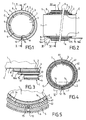
- the section T has a multilayer structure with, from the inside to the outside, a first watertight pipe 1, a first insulation layer called a primary insulation layer 2, a second watertight pipe 3, a second insulation layer called secondary insulation layer 4, a protective film 13, a concrete coating 5 and a protective envelope 6.
- a section T comprises a first pipe 1, of cylindrical shape and circular section.
- This first pipe 1 is waterproof and consists of a low coefficient of expansion material. It may for example consist of Invar especially available from Imphy Alloys.
- the first pipe 1 passes the transported fluid, which is preferably liquefied gas in its slot 7. It constitutes a first sealing barrier vis-à-vis the transported fluid.
- a primary insulation layer 2 surrounds the first pipe 1 at its outer surface.
- This primary insulation layer 2 is less extended longitudinally than the primary pipe 1. It consists of a low thermal conductivity material that is less than 20.10 -3 Wm -1 .K -1 at room temperature.
- This material may for example be an airgel whose thermal conductivity is less than 16 ⁇ 10 -3 Wm -1 .K -1 at -160 ° C.
- the airgel used in this insulating layer 2 is in the form of balls. Suitable airgel beads are available from CABOT corporation.
- O-shaped obstruction devices 8 occupy the end of the primary insulation layer 2, at each end E of the sections T.
- the primary insulation layer 2 comprises longitudinally pairs of spacing bars 14 spaced in the azimuthal direction. These bars 14, according to Figures 4 and 5 , are spaced at an angle substantially equal to 90 ° and are situated on either side of the lower generatrix line of the primary insulation layer 2. According to the figure 6 each section T has five pairs of spacer bars 14.
- the obstruction devices 8 and the spacer bars 14 are preferably made of a material of thermal conductivity close to that of the airgel of the layer 2 and permeable to gases. This material may for example be a phenolic foam or a polyurethane foam.
- the spacer bars 14 may be spaced at a different angle and may vary in number, size, shape, and azimuth arrangement. It can also be envisaged that these spacer rods 14 are in the form of a single longitudinal alignment of cleats at the level of the lower generative line of the primary insulation layer 2.
- the primary insulation layer 2 serves to limit the heat input from the external environment to the first pipe 1.
- the obstruction devices 8 make it possible to confine the airgel balls in the primary insulation layer 2.
- a first obstruction device 8 is placed at one end of the primary insulation layer 2 in order to form a waterproof vase.
- a second obstruction device 8 is placed at the other end of the primary insulation layer 2 after having filled the latter with airgel balls.
- the support of the first pipe 1 by the second pipe 3 is provided by at least one spacer bar present in the primary insulation layer 2, that is to say the pairs of spacer bars 14 in the example represent. Indeed, said spacer bars 14 make it possible to transmit the dead weight of the first pipe 1 to the second pipe 3 without damaging the primary insulation layer 2.
- the obstruction devices 8 are preferably gas-permeable, which makes it possible to circulate an inerting gas, which may be nitrogen, within the primary insulation layer 2, making it possible to avoid the forming an explosive mixture due to bringing the transported fluid into contact with air in the event of a leakage of the first pipe 1.
- the inerting gas sweeps the primary insulation layer 2 may be carried out by injecting dinitrogen at one end of the primary insulation layer 2.
- the circulation of the inert gas may be carried out by pressurizing at one of the ends of the primary insulation layer 2 and drawing to the other.
- the inerting of the primary insulation layer 2 may allow a control of the gas present in this layer 2 and consequently the detection of a possible leak.
- each obstruction device 8 is traversed longitudinally by eight holes 9. These holes 9 are plugged with a gas-permeable material. However, if the obstruction devices 8 are gas permeable, the holes 9 are then optional.
- the holes 9, whose number and arrangement can vary in the obstruction devices 8 and plugged with a gas-permeable material, such as bonded glass fabric, have the purpose of facilitating the circulation of the inerting gas while not allowing the primary insulation layer 2 to escape, ie the airgel balls.
- the second pipe 3 is made of the same material and has the same thickness. that the first pipe 1. It differs from the first pipe 1 in that it is less longitudinally extended than the first pipe 1 at each end E. It can also be seen that the second pipe 3 has the same length as the primary layer of insulation 2 underlying. This implies that a corresponding clearance is provided between the first pipe 1 and the second pipe 3.
- This second pipe 3 also constitutes a sealing barrier against the fluid transported in the event of invasion of the primary insulation layer 2 by gas as a result of leakage of the first pipe 1.
- the second pipe 3 also plays a role in reducing the contraction of the pipe C compared to conventional pipes. Indeed, being made of a material with a low coefficient of expansion such as the Invar as the first pipe 1, it expands much less than any other metal and, like the first pipe 1, avoids the installation of means for compensating the expansion stresses, for example compensators in lyre or bellows.
- a secondary insulation layer 4 surrounds the second pipe 3.
- This secondary insulation layer 4 consists of two superimposed layers, the inner layer 41 and the outer layer 42. They consist of a material with a low thermal conductivity which can for example be a nano-porous material in airgel, preferably in textile form of thermal conductivity of 12.10 -3 Wm -1 .K -1 to -160 ° C. This material will also be advantageously permeable to gases.
- An appropriate airgel fabric is available in particular from ASPEN aerogels.
- Each inner 41 or outer 42 layer consists of two half-shells similarly to the layers 141 and 142 shown on the drawing. figure 9 . In a particular example, the thickness of the inner insulation layer 41 is 19.2 mm and that of the outer layer 42 of 22.4 mm.
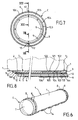
- the half-shells forming the outer layer 42 are dimensioned, in particular thickness, so as to accommodate a hollow sheath 15 of circular section which passes longitudinally along the length of the section T, at the lower junction of the two half-shells constituting the layer. external 42.
- This sheath 15 is intended to house an optical fiber or any other leak detection and localization system.
- the sheath 15 has a tapered flared end 16a which connects with the other end 16b of the sheath 15 of an adjacent T-section.
- the secondary insulation layer 4 is less extended longitudinally than the second pipe 3. This implies that an additional clearance is provided between the secondary insulation layer 4 and the second pipe 3.
- the secondary insulation layer 4 may be constituted a different number of layers, be made of another material or not to accommodate, in its thickness, a sheath 15 for optical fiber.
- the secondary insulation layer 4 serves to limit the heat input from the external environment to the second pipe 3. It also serves to thermally isolate the outside of the second pipe 3 and avoids excessive cooling of the protective envelope 6 external in case of invasion of the primary layer of insulation 2 by liquefied gas following a leakage of the first pipe 1.
- the secondary insulation layer 4 is preferably gas permeable. This implies that it is also possible to circulate an inerting gas, which may be nitrogen, within this insulating layer 4 for a purpose similar to that previously described for the insulating layer 2.
- the optical fiber is part of a leak detection device.
- This leak detection and localization device is a linear temperature sensor for distributed optical fiber (DTS) used to detect and locate any abnormal cold point within the outer layer 42 due to a possible liquefied gas leak.
- DTS distributed optical fiber
- the optical fiber is placed in the sheath 15 once the pipe C is assembled. It can be pulled along the pipe with an aramid fiber for example, or can be pushed with compressed air. It can be replaced in the same way that it was set up, without intervention on the pipe C, by pulling for example with the same aramid fiber along the pipe.
- the positioning of the optical fiber is preferable in the outer layer 42 of the secondary insulation layer 4 for several reasons. Firstly, at this location, in the event of a possible leak, the optical fiber detects significant variations in amplitudes and does not undergo thermal cycles that are too wide and could adversely affect its operation. Finally, at this position, the signal amplitude of the optical fiber remains acceptable despite the low temperature.
- a protective envelope 6, also of circular section, is arranged coaxially around the secondary insulation layer 4, at a distance from the latter.
- the protective envelope 6 is provided, at its upper generatrix line, with lifting devices 61.
- the lifting devices 61 are in the form of a bar of shorter length than that of the section T, disposed in the longitudinal direction of the section T and halfway between the ends E.
- the lifting devices 61 are traversed transversely by orifices. 62.
- the protective envelope 6 is made of steel provided with an extra thickness and an anti-corrosion coating to thereby limit corrosion by seawater. The extra thickness also protects the pipe C from external shocks.
- the hoisting devices 61 when they allow, the pipe C to be raised and manipulated via their orifices 62.
- the protective envelope 6 is less extended longitudinally than the secondary insulation layer 4, this creating an additional clearance between the outside of the pipe C and the secondary insulation layer 4.
- a protective film 13 may be placed around the secondary insulation layer 4 to prevent its invasion by the concrete.
- a concrete coating 5 is poured and fills the tubular space between the central part of the pipe (pipe 1, insulation layer 2, pipe 3, insulation layer 4 and any protective film 13) and the envelope Protective 6.
- a hollow conduit 12 is disposed in the longitudinal direction and along the entire length of the section T. This hollow conduit 12 may have a circular section.
- the concrete coating 5 makes it possible to give a total density of the vacuum pipe greater than that of the seawater so that the pipe C naturally rests on the bottom of the water in the empty state (density of the concrete loaded with the order of 3).
- the apparent mass of the submerged pipe must be greater than 10 kg per meter. This limits the movements suffered by the pipe C and therefore its damage.
- the hollow conduit 12 not only serves to purge the infiltration of seawater into the concrete coating 5 as a result of a possible leakage of the protective envelope 6 surrounding it, but also to evacuate the water resulting from the drying of the poured concrete and possibly also to circulate an inert gas.
- the hollow conduit 12 serves the function of drying or ventilating the pipe.
- the protective film 13 possibly placed around the secondary insulation layer 4 serves to protect the latter from invasion by the concrete slag 5 when it is poured into the protective envelope 6. It must also protect the layer secondary insulation 4 of the abrasive effect of the concrete coating 5 and the possible friction between the secondary insulation layer 4 and the concrete coating 5 due to the differences in thermal contraction during the passage of liquid gas.
- the pipe C is formed of sections T connected end to end at the ends E.
- the sections T measure for example four meters long. They are connected end to end to form a pipe C of the desired length, for example about 5000 m.
- the length of the sections T and their number can obviously vary according to the applications.
- the different elements constituting a section T have, with respect to each other, a longitudinal extension which is reduced in the radial direction towards the outside.
- This stepped structure of the ends E of the section T makes it possible to facilitate the welding operations of the different sections T between them. Indeed, this structure creates clearances that facilitate access to the deepest structures such as the first pipe 1. The release thus created will also provide the contribution of inserts for welds and the positioning of layers of materials. insulation at the connections.
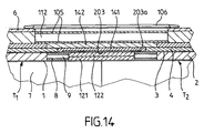
- the first pipes 1 of the two adjacent sections T1 and T2 are welded end to end by a weld bead.
- the internal 121 and external 122 primary insulation layers are each formed of a pair of half-shells, represented on the figure 9 made of insulating material, for example in textile form which may be airgel.
- the junction planes of the two pairs of half-shells are perpendicular to each other.
- the second pipes 3 of the two sections T1 and T2 are welded to each other by means of inserts which are, according to the embodiment shown, in the form of half-shells 103, but which can also be in the form of a split ring.
- inserts which are, according to the embodiment shown, in the form of half-shells 103, but which can also be in the form of a split ring.
- the two half-shells 103 in Invar are sealingly welded to the second pipes 3 by peripheral weld seams and to each other by longitudinal weld seams.
- the inner and outer secondary insulation layers 141 141 have the same constitution as the inner 121 and outer 122 primary insulation layers previously mentioned.
- the outer layer 142 of secondary insulation passes the sheath 15 at the lower seam of its two half-shells. Moreover, the sheath 15 of the optical fiber is slid into this joint after welding the half-shells 103 so that not interfere with this weld.
- the use of pairs of preformed half-shells for the primary insulation 102 and secondary 104 layers simplifies the operations of handling and implementation of the insulation.
- the use of pairs of half-shells of different colors simplifies the installation.
- each half-shell 105 is traversed longitudinally by a hollow conduit 112 at its upper generatrix line.
- the hollow duct 112 of the lower half-shell makes it possible to connect the hollow ducts 12 of the successive sections T1 and T2.
- a protective film 13 which is not shown on the figure 9 may optionally be reported between the secondary layers of insulation 104 and the half-shells of concrete 105.
- the protective shells 6 of the two sections T1 and T2 are connected by means of an external insert which is advantageously in the form of a split ring 106 matched to the adjacent tube 6 of larger diameter.
- the split ring 106 is fed longitudinally along one of the sections to the level of the connection to be welded to the ends of the protective shells 6 of the adjacent sections T1 and T2 by two sealed peripheral sealing beads.
- the inner diameter of the first pipe 1 is 800 mm and its thickness of 3 mm. The inside diameter is justified by the first estimates of pressure drop.
- the thickness of the first pipe 1 was sampled at 3 mm according to the stopping pressure of the pumps of a LNG tanker, admitting a stress equal to 66% of the yield point.
- the thickness of the primary insulation layer 2 is 40 mm.
- the second pipe 3 has an outer diameter of 892 mm and is less longitudinally extended than the first pipe 1 of 150 mm at each end E.
- the secondary layer 4, also of a thickness of 40 mm is less extended longitudinally than the second pipe 3 of 100 mm at each end E.
- the protective envelope 6 has a thickness of about 16 mm.
- the concrete coating 5 has a thickness of about 55 mm and the hollow conduit 12 has a diameter of about 40 mm.
- the length of the first pipe 1 is 4000 mm, that of the primary insulation layer 2 and the second pipe 3 of 3700 mm, that of the secondary insulation layer 4, the film of protection 13, and the protective envelope 6 of 3500 mm and that of the concrete coating of 3480 mm.
- a marine terminal is described in which the pipe C described above is used for the transport of liquefied gas between a loading and unloading station P and an installation on shore I.
- the number 75 designates the sea level.
- a loading and unloading station P is called a fixed off-shore installation.
- the loading and unloading station P comprises a movable arm 71, a platform 24 supported by pillars 70, which supports the movable arm 71.
- a fixed concrete tower 25 is built under the platform 24.
- the movable arm 71 carries a sleeve (not shown on the figure 10 ) can connect to the loading / unloading pipes of a LNG carrier according to the known technique.
- the movable arm 71 is connected to a connecting pipe 23 which extends between the platform 24 and the bottom of the water F inside the fixed tower 25.
- the connecting pipe 23 is connected to pipe C by a fixed abutment piece B embedded in concrete 26.
- the loading and unloading station P through its movable movable arm 71 which fits all the LNG carriers, allows the loading or unloading of the LNG carrier (not shown) in liquid.
- the onshore installation I also comprises a connecting pipe 23a which is connected to liquefied gas storage tanks (not shown) and which extends to the bottom of the water F inside a tower fixed 25a.
- the connecting pipe 23a is also connected to the pipe C by a fixed abutment piece B embedded in the concrete 26.
- the non-submerged connecting pipes 23 and 23a can be designed according to the known technique , for example in the form stainless steel pipes with adequate insulation and compensation systems.
- the ends of the pipe C are anchored to fixed abutment pieces B at a loading or unloading station P and an earth installation I.
- the pipe C which connects the loading and unloading station P and the shore facility I rests on the bottom of the water F. It allows the transfer of the liquefied gas between the loading or unloading station P and the installation on land I over a large distance, for example 5 km, which allows to place the post P at a great distance from the coast.
- Two ducts C sized according to the example above can transport the liquefied gas at a rate of 6000 m 3 / h, which allows the transfer of a cargo of a methane tanker of 144,000 m 3 in twelve hours.
- a pipe C according to the invention may also be provided between the loading and unloading station P and the shore installation I for conveying gas in vapor form. It is functionally different but physically identical to the two aforementioned pipes, which carry liquefied gas. This pipe serves, during the unloading of the LNG carrier, to convey to the LNG carrier, the volume of gas in vapor form necessary to replace the volume of the liquid gas that is discharged.
- the laying of the pipe C comprises the steps of pre-assembly on the ground of the sections T, then assembly at sea of the pre-assembled sections T and the connection of the pipe C to the fixed abutment parts B.
- a pre-assembly of sections T of 4 meters in sets of 40 to 60 meters for example can be performed.
- the assembly of the pre-assembled sections T of 40 to 60 meters can be envisaged from a barge ensuring an installation in S.
- the barge must be equipped with a stinger to support the portion of pipe C in suspension between the F water bottom and barge.
- An installation from the ground can also be considered.
- Each fixed stop piece B is composed different elements which are: an inner flange 17, an outer flange 18 and a cover 19.
- the inner flange 17 comprises a pipe 17b whose inner surface has a shoulder 17c and the outer surface has a radially projecting peripheral flange 17a.
- the outer diameter is decreasing from the rim 17a towards the end facing the cover 19.
- the outer flange 18 has three parts: a pipe 18b, a radially outer peripheral flange 18a at its end facing the cover 19 and a radially inner annular flange 18c between the two ends of the pipe 18b.
- the inside diameter of the annular flange 18c substantially corresponds to the outside diameter of the portion of the pipe 17b situated between the flange 17a and the end facing towards the pipe C.
- the outer flange 18 comprises a series of threaded studs 18d disposed on the face of the flange. 18a turned towards the cover 19.
- the outer diameter of the outer flange 18 is slightly decreasing in the portion between the flange 18a and the end S3 connected with the protective envelope 6 of the pipe C
- the cover 19 is substantially in the form of a disk traversed longitudinally by orifices 19b arranged on a circle concentric with the axis of revolution of the cover.
- the lid 19 also has a central opening 19c whose diameter substantially corresponds to the outside diameter of the pipe 17b.
- the cover 19 also has ribs 19a protruding on its face opposite to the outer flange 18 which promote heat exchange on the one hand and stiffen the lid 19 on the other.
- concrete 26 surrounds the outer surface of the pipe 18b and the end E of the pipe C connected thereto.
- the end E of the pipe C is assembled to the fixed abutment piece B preferentially out of the water, then the assembly is immersed after placing a plug to be fixed in the concrete.
- the end E of the pipe C is pushed into the pipe lumen 17b of the inner flange 17 without reaching the shoulder 17 c.
- the end of the first pipe 1 is welded to the inner surface of the pipe 17b between the end S1 and the shoulder 17c.
- the second pipe 3 is welded to the outer surface of the pipe 17b between the end S2 and the radially inner flange 18c of the outer flange 18, the thickness of the pipe 17b on this portion corresponding exactly to the thickness between the first pipe 1 and the second pipe 3.
- An insulating element 22 is placed in the space defined between the flange 18c and the end of the secondary insulation layer 4 and the concrete coating 5.
- the insulating element 22 makes it possible to extend the insulation of the layer secondary insulation 4 and the concrete coating 5 within the outer flange 18.
- the internal flange 17 is positioned longitudinally relative to the outer flange 18 by inserting a first positioning wedge 20a between the radially inner flange 18c and the radially outer flange 17a of the inner flange 17.
- a weld is made at the end S3 solidarisant the protective envelope 6 and the outer flange 18.
- a second positioning wedge 20b is placed against the flange 17a opposite the first positioning wedge 20a.
- the cover 19 is then placed against the second positioning wedge 20b and the radially outer flange 18a by engaging the studs 18d through the orifices 19b. Then the cover 19 is held in abutment by nuts 21 screwed on the studs 18d. The cover 19, bearing against the wedge 20b, ensures the immobilization of the inner flange 17 in the outer flange 18.
- the mounting of the fixed stop B can also be considered under water.
- the pipe C is able to be extended between the loading and unloading stations P and the shore installation I without providing devices. Compensation for thermal shrinkage. This results in a reduction of the pressure losses and an improvement of the transported flow.
- the fixed stop pieces B are designed and fixed so as to withstand the thermal contractions due to the transport of the liquefied gas.
- the fixed stops B then constitute heat recovery elements.
- the tensile forces due to the cooling of the pipes 1 and 3 and possibly the cooling of the outer protective shell 6 - whose temperature follows that of the surrounding environment - are partially compensated - during unloading - by the background effect which corresponds to the pressure drop in the pipe 1 applied to the passage section.
- the constraints due to the background effect are low compared to those due to the retraction of materials.
- the internal design pressure used is a pressure of 1.5 times the stop pressure of the pumps of the LNG tanker that delivers the liquid, ie 15 bar. This pressure of 15 bar is provided to be supported by the first pipe 1, and possibly by the second pipe 3 which must withstand this pressure if the first pipe 1 gives way.
- the protective envelope 6 must withstand twice the immersion pressure that is to say about 7 bar.
- the internal pressure of the protective envelope 6 under water is the atmospheric pressure because the space between the pipe 3 and the envelope 6 communicates with the atmosphere through the abutment piece B. Its external pressure, due to the immersion under 30 m of water and 5 m of tide is about 3.5 bars.
- the minimum thicknesses eMin calculated to withstand the internal pressure at each pipe are 1.49 mm for the first pipe 1 and 1.75 mm for the second pipe 3.
- the minimum thickness for the protective shell 6 is 2.63 mm when line C is immersed 30 m under water.
- This diagram represents the operating temperature (in ° C) as a function of the distance from the center of the pipe C (in mm).
- the operating temperature is the temperature in the various elements of the pipe during the transport of liquid gas.
- Curve 72 represents the case where the temperature outside line C is 4 ° C.
- Curve 73 represents the case where the temperature outside line C is 30 ° C.
- the two curves show the same general evolution.
- the temperature increases from the center of the pipe C towards the outside.
- Each curve is composed of six points.
- the first point of each curve, at the temperature of about -160 ° C represents the temperature inside the first pipe 1, the second point: the one outside the first pipe 1, the third point: the one on the outside. inside the second pipe 3, the fourth point: the one outside the second pipe 3, the fifth point: that outside the concrete coating 5 and the sixth point: the outside of the protective envelope 6, that is to say the surrounding marine environment.
- the temperature gradient is important. This means that the primary insulation layer 2 plays its role of thermal insulation.
- the temperature is about -100 ° C for the first curve 72 and -85 ° C for the second 73. It is found that the temperatures at the second pipe 3 are still very cold.
- the structure of the sections T according to the second embodiment is identical to that of the sections T according to the first embodiment.
- the structure of the sections T according to the second embodiment is therefore illustrated by the Figures 1 to 5 .
- the pipe C according to the second embodiment has connections between sections which differ from the connections of the first embodiment because they comprise thermal contraction compensation systems 30 interconnecting the first pipes 1 and / or the second pipes 3.
- a thermal contraction compensation system 30 is shown partially on the figure 13 .
- This is a tubular sleeve 31 which has at its two ends, an inner diameter corresponding to the outer diameter of the first pipes 1 or second pipes 3 to be connected.
- This last feature allows the sleeve 31 to accommodate the ends of the first pipe 1 or the second pipe 3.
- the ends 34 of the sleeve 31 are then welded by a sealed peripheral sealing bead to the surface of the first pipe 1 or the second pipe 3 .
- the sleeve 31 connects two first pipes 1 or second pipes 3 belonging to two adjacent sections T1 and T2.
- the sleeve 31 is made of a material allowing an assembly adapted by gluing or welding for example to the adjacent pipes 3. It has at least one circumferential radial ripple 32 accordion-shaped in its central position, that is to say three corrugations 32 in the example shown. During the transport of the liquefied gas, the structure formed by the waves 32 stretches and settles with the deformations of the corresponding pipe due to temperature variations. The sleeve 31 therefore constitutes a local heat recovery element.
- the thermal contraction compensation systems 30 are arranged astride the second pipes 3 of two adjacent sections T1 and T2, ie in place of the inserts 103 of the first embodiment of FIG. embodiment and / or between the first pipes 1.
- the other elements making up the connection are identical to those of the first embodiment. .
- the second embodiment of line C is advantageous in that it allows the first 1 and / or the second 3 pipes to be made of material which does not have a low coefficient of expansion, unlike in the first embodiment, by example stainless steel, various alloys or composite materials. This results in an economic benefit.
- the compensation systems are used in stainless steel pipes or other expandable material. Pipes not made of a low coefficient of expansion material shrink longitudinally intensely when cold, which, in the absence of appropriate compensation, could result in tearing of the anchoring of the ends of the pipe C or the own tearing of the pipe if the anchorage resisted these constraints.
- connections according to the Figures 7 to 9 can also be used alternately with compensation systems 30.
- the structure of the connections without compensation system 30 is then identical to that of the first embodiment, except that the pair of half-shells 103 for welding the second pipe 3 is a material not necessarily low thermal expansion, but compatible with the assembly mode.
- the ends of the pipes C according to the second embodiment can also be anchored by fixed stops B to a loading and unloading station P and to an installation on land I in a manner identical to that of the first embodiment with reference to the figures 10 and 11 .
- the pipe may differ from the pipes described in the previous embodiments in that it comprises a second pipe 3 made of composite material.
- the ends of the second pipes 3 adjacent are then connected by a joint cover 203 of material composite flexible, for example the Triplex (trademark), whose ends 204a overlap and are adhered to the outer surface of the ends of the second pipes 3 adjacent.
- the composite material is constituted for example by a fiber-reinforced polymer resin, for example a polyester or epoxy resin reinforced with glass or carbon fibers, optionally woven.
- the composite material may also be composed so as to have mechanical properties satisfying the criterion: Re> E. ⁇ . DT.
- Triplex is a three-layered material consisting of two outer layers of fiberglass fabric and an intermediate layer of thin metal foil. Triplex is marketed by Hutchinson.
- second pipes 3 of composite material allows a significant reduction in the cost of manufacturing the pipes.
Landscapes
- Engineering & Computer Science (AREA)
- General Engineering & Computer Science (AREA)
- Mechanical Engineering (AREA)
- Thermal Insulation (AREA)
- Filling Or Discharging Of Gas Storage Vessels (AREA)
- Rigid Pipes And Flexible Pipes (AREA)
- Pipeline Systems (AREA)
- Fuses (AREA)
- Insulated Conductors (AREA)
- Insulators (AREA)
- Linear Motors (AREA)
- Cylinder Crankcases Of Internal Combustion Engines (AREA)
Priority Applications (1)
| Application Number | Priority Date | Filing Date | Title |
|---|---|---|---|
| CY20081100548T CY1107968T1 (el) | 2004-01-20 | 2008-05-26 | Θερμικα μονωμενος αγωγος |
Applications Claiming Priority (2)
| Application Number | Priority Date | Filing Date | Title |
|---|---|---|---|
| FR0400509A FR2865262B1 (fr) | 2004-01-20 | 2004-01-20 | Conduite thermiquement isolee |
| FR0400509 | 2004-01-20 |
Publications (2)
| Publication Number | Publication Date |
|---|---|
| EP1557602A1 EP1557602A1 (fr) | 2005-07-27 |
| EP1557602B1 true EP1557602B1 (fr) | 2008-03-26 |
Family
ID=34630652
Family Applications (1)
| Application Number | Title | Priority Date | Filing Date |
|---|---|---|---|
| EP04293045A Expired - Lifetime EP1557602B1 (fr) | 2004-01-20 | 2004-12-20 | Conduite thermiquement isolée |
Country Status (17)
| Country | Link |
|---|---|
| US (1) | US20050155663A1 (es) |
| EP (1) | EP1557602B1 (es) |
| JP (1) | JP2005207592A (es) |
| KR (1) | KR100650827B1 (es) |
| CN (1) | CN100567788C (es) |
| AT (1) | ATE390601T1 (es) |
| AU (1) | AU2005200038B2 (es) |
| CA (1) | CA2491675C (es) |
| CY (1) | CY1107968T1 (es) |
| DE (1) | DE602004012701D1 (es) |
| EG (1) | EG23700A (es) |
| ES (1) | ES2304591T3 (es) |
| FR (1) | FR2865262B1 (es) |
| MX (1) | MXPA05000509A (es) |
| MY (1) | MY138600A (es) |
| PT (1) | PT1557602E (es) |
| TW (1) | TWI279503B (es) |
Families Citing this family (58)
| Publication number | Priority date | Publication date | Assignee | Title |
|---|---|---|---|---|
| FR2858841B1 (fr) * | 2003-08-14 | 2007-02-09 | Technip France | Methode de drainage et d'evacuation des gaz de permeation d'une conduite tubulaire flexible et conduite adaptee a sa mise en oeuvre |
| US20060207673A1 (en) * | 2005-03-18 | 2006-09-21 | O'brien John V | Vacuum insulated assured flow piping |
| US8505857B2 (en) | 2006-08-18 | 2013-08-13 | Kellogg Brown & Root Llc | Systems and methods for supporting a pipe |
| US7997541B2 (en) * | 2006-08-18 | 2011-08-16 | Kellogg Brown & Root Llc | Systems and methods for supporting a pipe |
| KR100948578B1 (ko) * | 2006-12-12 | 2010-03-18 | 한국생산기술연구원 | 에어로겔 단열시트를 구비하는 단열관 |
| US8127801B2 (en) * | 2007-04-29 | 2012-03-06 | Brower David V | Advance instrumentation methods for pipes and conduits transporting cryogenic materials |
| US7794805B2 (en) * | 2007-06-29 | 2010-09-14 | Schlumberger Technology Corporation | Thermal insulation barriers |
| RU2365889C1 (ru) * | 2007-12-29 | 2009-08-27 | Шлюмберже Текнолоджи Б.В. | Способ определения места утечки газа из подземного трубопровода (варианты) |
| PL2095938T3 (pl) | 2008-02-29 | 2015-08-31 | Lethe Naval Gmbh | Izolacja rur pozbawiona formaldehydu |
| JP5227635B2 (ja) * | 2008-03-28 | 2013-07-03 | 古河電気工業株式会社 | 流体漏洩検知システム |
| JP5184177B2 (ja) * | 2008-03-28 | 2013-04-17 | 古河電気工業株式会社 | 極低温流体輸送用可撓管 |
| US9267330B2 (en) * | 2008-08-20 | 2016-02-23 | Foro Energy, Inc. | Long distance high power optical laser fiber break detection and continuity monitoring systems and methods |
| DE102008056987A1 (de) * | 2008-11-12 | 2010-05-20 | Rwe Power Ag | Isolierkassette |
| WO2011079844A1 (en) * | 2009-12-31 | 2011-07-07 | Kirkegaard Kim Joergen Schultz | A cement-based material comprising a nano-aerogel insulating tape material |
| FR2964456B1 (fr) * | 2010-09-08 | 2013-05-10 | Commissariat Energie Atomique | Dispositif de detection de fuite et revetement d'organe de transport ou de stockage de fluide comportant ce dispositif de detection |
| KR101182204B1 (ko) * | 2010-10-08 | 2012-09-14 | (주)나우이엔씨 | 방폭형 인라인히터 |
| PT2472165E (pt) * | 2010-12-30 | 2014-08-29 | Shell Int Research | Conjunto de túnel e método de transferência de fluido criogénico |
| BR112013016485A2 (pt) * | 2011-01-06 | 2016-09-27 | Nat Oilwell Varco Denmark Is | tubo flexível não unido para o transporte submarino de fluidos, instalação fora da costa, e, método de manutenção de um tubo flexível não unido de uma instalação fora da costa |
| CA2829288A1 (en) | 2011-01-25 | 2012-08-02 | Rns Technologies Bv | Insulation composition and method to detect water in an insulation composition |
| US9976687B2 (en) | 2012-05-18 | 2018-05-22 | Saprex, Llc | Breathable multi-component exhaust insulation system |
| US9388515B2 (en) | 2012-09-28 | 2016-07-12 | Saprex, Llc | Heat curable composite textile |
| FR2997747B1 (fr) * | 2012-11-08 | 2015-01-16 | Technip France | Conduite flexible de transport d'un fluide cryogenique, installation et procede associes |
| US9523512B2 (en) * | 2013-09-27 | 2016-12-20 | Flexible Technologies, Inc. | Insulated duct with air jacket and method of use |
| CN103591412A (zh) * | 2013-10-30 | 2014-02-19 | 惠生(南通)重工有限公司 | 一种绝热超低温管 |
| CN103557404B (zh) * | 2013-11-06 | 2015-11-25 | 北京豪特耐管道设备有限公司 | 一种绝热管道的生产方法及采用该方法生产的绝热管道 |
| CN103557405B (zh) * | 2013-11-06 | 2015-10-14 | 北京豪特耐管道设备有限公司 | 带有泄漏监测系统的预制绝热管生产工艺及其吊锤 |
| CA2929636A1 (en) * | 2013-11-08 | 2015-05-14 | Shawcor Ltd. | Thermally insulated tubular |
| FR3013816A1 (fr) * | 2013-11-26 | 2015-05-29 | Air Liquide | Element de support, circuit de fluide cryogenique et procede correspondants |
| CN204062204U (zh) * | 2014-04-03 | 2014-12-31 | 刘兴仁 | 一种耐磨防腐内衬隔热油管 |
| US10160655B2 (en) | 2014-05-15 | 2018-12-25 | Tahoe Technologies, Ltd. | Apparatus and method for manufacturing and packaging of high performance thermal insulator aerogels |
| FR3021385B1 (fr) * | 2014-05-23 | 2017-01-20 | Itp Sa | Troncon pour un conduit double enveloppe monte par vissage thermiquement isole et chauffe et son procede de mise en oeuvre |
| US10378296B2 (en) * | 2014-10-23 | 2019-08-13 | Halliburton Energy Services, Inc. | Sealed downhole equipment and method for fabricating the equipment |
| CN104373755B (zh) * | 2014-10-27 | 2016-08-17 | 宁夏天纵泓光余热发电技术有限公司 | 矿热炉烟气真空浇筑料保温管 |
| BR112017007242A2 (pt) * | 2014-11-25 | 2018-01-16 | Halliburton Energy Services Inc | transportes tubulares, e, conjuntos. |
| GB2533936B (en) | 2015-01-07 | 2017-10-25 | Homeserve Plc | Flow detection device |
| GB201501935D0 (en) | 2015-02-05 | 2015-03-25 | Tooms Moore Consulting Ltd And Trow Consulting Ltd | Water flow analysis |
| BR112018008814B1 (pt) | 2015-11-02 | 2022-07-12 | Flexsteel Pipeline Technologies, Inc | Método de monitoramento de integridade em tempo real de tubos terrestres |
| CN105485432B (zh) * | 2016-01-28 | 2017-08-29 | 沈圣良 | 一种高温管道固定支架及高温管道固定方法 |
| USD800591S1 (en) | 2016-03-31 | 2017-10-24 | Homeserve Plc | Flowmeter |
| FI3443254T3 (fi) * | 2016-04-15 | 2024-03-18 | Saprex Llc | Komposiittieristysjärjestelmä |
| US11946584B2 (en) | 2016-11-18 | 2024-04-02 | Nelson Global Products, Inc. | Composite insulation system |
| CN106704768A (zh) * | 2017-01-24 | 2017-05-24 | 高新伟 | 一种地上公共燃气管道的防护方法 |
| US10677260B2 (en) * | 2017-02-21 | 2020-06-09 | General Electric Company | Turbine engine and method of manufacturing |
| RU182117U1 (ru) * | 2018-02-27 | 2018-08-03 | Общество С Ограниченной Ответственностью "Бт Свап" | Устройство для компенсации напряжений и защиты стыков трубопроводов с бетонным покрытием от нагрузок и воздействий |
| KR102112197B1 (ko) * | 2019-10-08 | 2020-05-19 | (주)동인엔지니어링 | 저온배관용 단열장치 |
| RU2754833C1 (ru) * | 2020-08-04 | 2021-09-07 | Акционерное Общество "Российский Концерн По Производству Электрической И Тепловой Энергии На Атомных Станциях" (Ао "Концерн Росэнергоатом") | Блочная тепловая изоляция отражательного типа для трубопроводов и/или оборудования реакторных установок |
| CN112128494B (zh) * | 2020-08-24 | 2023-12-01 | 上海齐耀动力技术有限公司 | 一种真空夹层管道用法兰接头以及真空夹层管道组件 |
| CN112318946B (zh) * | 2020-10-30 | 2023-05-02 | 张家口宣化建投供热有限责任公司 | 一种热力资源输送管道用保温装置 |
| CN112319705B (zh) * | 2020-11-13 | 2022-05-10 | 上海海威斯特保温工程有限公司 | C型lng液货舱喷涂式绝热系统及其构建方法 |
| CN113983241A (zh) * | 2021-11-10 | 2022-01-28 | 上海外高桥造船有限公司 | 采用结构护圈加强管子的安装方法及加强管子组件 |
| CN114033922A (zh) * | 2021-11-18 | 2022-02-11 | 青海省水文地质工程地质环境地质调查院 | 一种适用干热岩单孔取热出汽装置中保温组合材料的制备方法 |
| EP4187726A1 (fr) * | 2021-11-29 | 2023-05-31 | Rte Reseau De Transport D'electricite | Procédé de colmatage d'une jonction à surface et contre-surface de contact d'un élément d'un compartiment de poste électrique sous enveloppe métallique à isolation gazeuse et jonction résultante |
| NO347314B1 (en) * | 2021-12-08 | 2023-09-11 | Nitrogas As | Method and a system for reducing corrosive environment for a pipeline |
| CN114576468A (zh) * | 2022-01-25 | 2022-06-03 | 华能澜沧江水电股份有限公司 | 一种引水式压力钢管保护装置 |
| CN116379226A (zh) * | 2023-04-06 | 2023-07-04 | 河南中烟工业有限责任公司 | 一种料液的管路系统 |
| CN117167585A (zh) * | 2023-11-03 | 2023-12-05 | 水利部交通运输部国家能源局南京水利科学研究院 | 一种刚柔结合的管内环向预应力加固方法 |
| FR3158997A1 (fr) | 2024-02-07 | 2025-08-08 | Itp Sa | Conduite à triple enveloppe pour le transport de liquide cryogénique |
| CN119900932B (zh) * | 2024-12-18 | 2025-10-31 | 国家石油天然气管网集团有限公司 | 天然气放空回收系统 |
Family Cites Families (15)
| Publication number | Priority date | Publication date | Assignee | Title |
|---|---|---|---|---|
| US2611567A (en) * | 1946-03-18 | 1952-09-23 | Alexander H Isenberg | Insulated pipe anchor |
| US2923650A (en) * | 1955-03-30 | 1960-02-02 | Seme Jean | Method of and device for heat-insulating piping for the long-distance conveyance of heating fluids |
| US3388724A (en) * | 1965-04-05 | 1968-06-18 | Exxon Research Engineering Co | Submarine insulated lng pipeline |
| FR2301761A1 (fr) * | 1975-02-24 | 1976-09-17 | Technigaz | Conduite pour le transport d'un fluide dont la temperature est differente de la temperature ambiante |
| US4014369A (en) * | 1975-12-31 | 1977-03-29 | Exxon Research And Engineering Company | Triple pipe low temperature pipeline |
| DE3314694A1 (de) * | 1983-04-22 | 1984-10-25 | Fried. Krupp Gmbh, 4300 Essen | Druckfester isolationskoerper mit kleiner waermeleitfaehigkeit und grosser festigkeit |
| USH594H (en) * | 1985-04-12 | 1989-03-07 | Exxon Production Research Company | Jacketed pipeline system with pressurized gas to resist external stress |
| US4718459A (en) * | 1986-02-13 | 1988-01-12 | Exxon Production Research Company | Underwater cryogenic pipeline system |
| US5795102A (en) * | 1992-08-12 | 1998-08-18 | Corbishley; Terrence Jeffrey | Marine and submarine apparatus |
| US5390961A (en) * | 1993-04-28 | 1995-02-21 | Thermon Manufacturing Company | Dual wall thermally insulated conduit including skin effect heat tracing pipes |
| FR2746891B1 (fr) | 1996-03-29 | 1998-06-05 | Itp | Tuyau pour canalisations du type a double enveloppe d'isolation thermique |
| FR2748545B1 (fr) | 1996-05-09 | 1998-08-07 | Total Sa | Conduite isolee thermiquement pour le transport de gaz naturel liquefie |
| US6527015B2 (en) * | 1999-07-02 | 2003-03-04 | F. Glenn Lively | Insulated pipe |
| WO2004090412A1 (en) * | 2003-04-02 | 2004-10-21 | Chart Industries, Inc. | Fluid piping systems and pipe spools suitable for sub sea use |
| KR101156311B1 (ko) * | 2003-05-06 | 2012-06-13 | 아스펜 에어로겔, 인코포레이티드 | 단열 파이프 라인 및 파이프 라인 단열 방법 |
-
2004
- 2004-01-20 FR FR0400509A patent/FR2865262B1/fr not_active Expired - Fee Related
- 2004-12-20 DE DE602004012701T patent/DE602004012701D1/de not_active Expired - Lifetime
- 2004-12-20 PT PT04293045T patent/PT1557602E/pt unknown
- 2004-12-20 EP EP04293045A patent/EP1557602B1/fr not_active Expired - Lifetime
- 2004-12-20 ES ES04293045T patent/ES2304591T3/es not_active Expired - Lifetime
- 2004-12-20 AT AT04293045T patent/ATE390601T1/de not_active IP Right Cessation
- 2004-12-30 CA CA002491675A patent/CA2491675C/fr not_active Expired - Lifetime
-
2005
- 2005-01-05 US US11/028,681 patent/US20050155663A1/en not_active Abandoned
- 2005-01-06 AU AU2005200038A patent/AU2005200038B2/en not_active Ceased
- 2005-01-11 MX MXPA05000509A patent/MXPA05000509A/es active IP Right Grant
- 2005-01-11 TW TW094100756A patent/TWI279503B/zh not_active IP Right Cessation
- 2005-01-17 EG EG2005010028A patent/EG23700A/xx active
- 2005-01-18 MY MYPI20050193A patent/MY138600A/en unknown
- 2005-01-19 JP JP2005012157A patent/JP2005207592A/ja active Pending
- 2005-01-19 CN CNB2005100055768A patent/CN100567788C/zh not_active Expired - Fee Related
- 2005-01-20 KR KR1020050005253A patent/KR100650827B1/ko not_active Expired - Fee Related
-
2008
- 2008-05-26 CY CY20081100548T patent/CY1107968T1/el unknown
Also Published As
| Publication number | Publication date |
|---|---|
| FR2865262A1 (fr) | 2005-07-22 |
| US20050155663A1 (en) | 2005-07-21 |
| MY138600A (en) | 2009-07-31 |
| JP2005207592A (ja) | 2005-08-04 |
| EG23700A (en) | 2007-05-22 |
| CA2491675A1 (fr) | 2005-07-20 |
| KR20050076684A (ko) | 2005-07-26 |
| AU2005200038A1 (en) | 2005-08-04 |
| AU2005200038B2 (en) | 2009-05-28 |
| FR2865262B1 (fr) | 2006-11-24 |
| CY1107968T1 (el) | 2013-09-04 |
| TW200526894A (en) | 2005-08-16 |
| TWI279503B (en) | 2007-04-21 |
| KR100650827B1 (ko) | 2006-11-27 |
| EP1557602A1 (fr) | 2005-07-27 |
| ATE390601T1 (de) | 2008-04-15 |
| DE602004012701D1 (de) | 2008-05-08 |
| CA2491675C (fr) | 2008-03-11 |
| PT1557602E (pt) | 2008-06-16 |
| MXPA05000509A (es) | 2005-11-17 |
| CN100567788C (zh) | 2009-12-09 |
| ES2304591T3 (es) | 2008-10-16 |
| CN1644972A (zh) | 2005-07-27 |
Similar Documents
| Publication | Publication Date | Title |
|---|---|---|
| EP1557602B1 (fr) | Conduite thermiquement isolée | |
| FR2475185A1 (fr) | Tuyau calorifuge flexible pour fluides notamment cryogeniques | |
| EP2606269B1 (fr) | Embout de connexion d'une conduite flexible de transport d'un fluide cryogénique. | |
| EP1562823B1 (fr) | Installation de transfert de gaz liquefie et son utilisation | |
| OA12630A (fr) | Installation de liaison d'une conduite sous-marinereliée à un riser. | |
| EP1366320B1 (fr) | Dispositif d'isolation thermique d'au moins une conduite sous-marine comprenant des cloisons etanches | |
| EP4399434A1 (fr) | Installation de stockage pour gaz liquéfié | |
| WO2021255000A1 (fr) | Dôme liquide d'une cuve de stockage pour gaz liquéfié | |
| EP3755939A2 (fr) | Installation de stockage et de transport d'un fluide cryogénique embarquée sur un navire | |
| FR2721681A1 (fr) | Procédé de construction de conduites telles que des canalisations de produits pétroliers en mer, tuyaux et dispositifs de raccordement de tuyaux pour la mise en Óoeuvre de ce procédé. | |
| WO1998034061A1 (fr) | Enveloppe d'isolation thermique, notamment pour la construction de canalisations sous-marines vehiculant des produits petroliers | |
| WO2021254999A1 (fr) | Dôme liquide d'une cuve de stockage pour gaz liquéfié | |
| EP1070907A1 (fr) | Procédé de réalisation d'une conduite calorifugée à enveloppe externe de protection et conduite ainsi réalisée | |
| WO2025168822A1 (fr) | Conduite à triple enveloppe pour le transport de liquide cryogénique | |
| FR2951802A1 (fr) | Conduite sous-marine appliquee a l'exploitation de l'energie thermique des mers | |
| FR2748545A1 (fr) | Conduite isolee thermiquement pour le transport de gaz naturel liquefie | |
| WO2025146381A1 (fr) | Cuve étanche et thermiquement isolante | |
| FR3135126A1 (fr) | Paroi de cuve traversée par une conduite étanche d’évacuation de fluide | |
| FR2636769A1 (fr) | Structure de reacteur nucleaire refroidi par metal liquide, du type a boucles, avec cuve posee | |
| WO2020089549A1 (fr) | Installation de stockage pour gaz liquefie | |
| EP0088706A1 (fr) | Procédé de construction de canalisation et ancrage |
Legal Events
| Date | Code | Title | Description |
|---|---|---|---|
| PUAI | Public reference made under article 153(3) epc to a published international application that has entered the european phase |
Free format text: ORIGINAL CODE: 0009012 |
|
| AK | Designated contracting states |
Kind code of ref document: A1 Designated state(s): AT BE BG CH CY CZ DE DK EE ES FI FR GB GR HU IE IS IT LI LT LU MC NL PL PT RO SE SI SK TR |
|
| AX | Request for extension of the european patent |
Extension state: AL BA HR LV MK YU |
|
| 17P | Request for examination filed |
Effective date: 20050917 |
|
| AKX | Designation fees paid |
Designated state(s): AT BE BG CH CY CZ DE DK EE ES FI FR GB GR HU IE IS IT LI LT LU MC NL PL PT RO SE SI SK TR |
|
| GRAP | Despatch of communication of intention to grant a patent |
Free format text: ORIGINAL CODE: EPIDOSNIGR1 |
|
| GRAS | Grant fee paid |
Free format text: ORIGINAL CODE: EPIDOSNIGR3 |
|
| GRAA | (expected) grant |
Free format text: ORIGINAL CODE: 0009210 |
|
| AK | Designated contracting states |
Kind code of ref document: B1 Designated state(s): AT BE BG CH CY CZ DE DK EE ES FI FR GB GR HU IE IS IT LI LT LU MC NL PL PT RO SE SI SK TR |
|
| REG | Reference to a national code |
Ref country code: GB Ref legal event code: FG4D Free format text: NOT ENGLISH |
|
| REG | Reference to a national code |
Ref country code: CH Ref legal event code: EP Ref country code: IE Ref legal event code: FG4D Free format text: LANGUAGE OF EP DOCUMENT: FRENCH |
|
| REF | Corresponds to: |
Ref document number: 602004012701 Country of ref document: DE Date of ref document: 20080508 Kind code of ref document: P |
|
| GBT | Gb: translation of ep patent filed (gb section 77(6)(a)/1977) |
Effective date: 20080421 |
|
| REG | Reference to a national code |
Ref country code: PT Ref legal event code: SC4A Free format text: AVAILABILITY OF NATIONAL TRANSLATION Effective date: 20080530 |
|
| REG | Reference to a national code |
Ref country code: GR Ref legal event code: EP Ref document number: 20080401149 Country of ref document: GR |
|
| PG25 | Lapsed in a contracting state [announced via postgrant information from national office to epo] |
Ref country code: FI Free format text: LAPSE BECAUSE OF FAILURE TO SUBMIT A TRANSLATION OF THE DESCRIPTION OR TO PAY THE FEE WITHIN THE PRESCRIBED TIME-LIMIT Effective date: 20080326 |
|
| PG25 | Lapsed in a contracting state [announced via postgrant information from national office to epo] |
Ref country code: AT Free format text: LAPSE BECAUSE OF FAILURE TO SUBMIT A TRANSLATION OF THE DESCRIPTION OR TO PAY THE FEE WITHIN THE PRESCRIBED TIME-LIMIT Effective date: 20080326 |
|
| NLV1 | Nl: lapsed or annulled due to failure to fulfill the requirements of art. 29p and 29m of the patents act | ||
| PG25 | Lapsed in a contracting state [announced via postgrant information from national office to epo] |
Ref country code: PL Free format text: LAPSE BECAUSE OF FAILURE TO SUBMIT A TRANSLATION OF THE DESCRIPTION OR TO PAY THE FEE WITHIN THE PRESCRIBED TIME-LIMIT Effective date: 20080326 Ref country code: SI Free format text: LAPSE BECAUSE OF FAILURE TO SUBMIT A TRANSLATION OF THE DESCRIPTION OR TO PAY THE FEE WITHIN THE PRESCRIBED TIME-LIMIT Effective date: 20080326 |
|
| REG | Reference to a national code |
Ref country code: ES Ref legal event code: FG2A Ref document number: 2304591 Country of ref document: ES Kind code of ref document: T3 |
|
| REG | Reference to a national code |
Ref country code: IE Ref legal event code: FD4D |
|
| PG25 | Lapsed in a contracting state [announced via postgrant information from national office to epo] |
Ref country code: SE Free format text: LAPSE BECAUSE OF FAILURE TO SUBMIT A TRANSLATION OF THE DESCRIPTION OR TO PAY THE FEE WITHIN THE PRESCRIBED TIME-LIMIT Effective date: 20080626 Ref country code: SK Free format text: LAPSE BECAUSE OF FAILURE TO SUBMIT A TRANSLATION OF THE DESCRIPTION OR TO PAY THE FEE WITHIN THE PRESCRIBED TIME-LIMIT Effective date: 20080326 Ref country code: CZ Free format text: LAPSE BECAUSE OF FAILURE TO SUBMIT A TRANSLATION OF THE DESCRIPTION OR TO PAY THE FEE WITHIN THE PRESCRIBED TIME-LIMIT Effective date: 20080326 |
|
| PG25 | Lapsed in a contracting state [announced via postgrant information from national office to epo] |
Ref country code: RO Free format text: LAPSE BECAUSE OF FAILURE TO SUBMIT A TRANSLATION OF THE DESCRIPTION OR TO PAY THE FEE WITHIN THE PRESCRIBED TIME-LIMIT Effective date: 20080326 Ref country code: NL Free format text: LAPSE BECAUSE OF FAILURE TO SUBMIT A TRANSLATION OF THE DESCRIPTION OR TO PAY THE FEE WITHIN THE PRESCRIBED TIME-LIMIT Effective date: 20080326 |
|
| PG25 | Lapsed in a contracting state [announced via postgrant information from national office to epo] |
Ref country code: IS Free format text: LAPSE BECAUSE OF FAILURE TO SUBMIT A TRANSLATION OF THE DESCRIPTION OR TO PAY THE FEE WITHIN THE PRESCRIBED TIME-LIMIT Effective date: 20080726 |
|
| PG25 | Lapsed in a contracting state [announced via postgrant information from national office to epo] |
Ref country code: IE Free format text: LAPSE BECAUSE OF FAILURE TO SUBMIT A TRANSLATION OF THE DESCRIPTION OR TO PAY THE FEE WITHIN THE PRESCRIBED TIME-LIMIT Effective date: 20080326 Ref country code: DK Free format text: LAPSE BECAUSE OF FAILURE TO SUBMIT A TRANSLATION OF THE DESCRIPTION OR TO PAY THE FEE WITHIN THE PRESCRIBED TIME-LIMIT Effective date: 20080326 Ref country code: LT Free format text: LAPSE BECAUSE OF FAILURE TO SUBMIT A TRANSLATION OF THE DESCRIPTION OR TO PAY THE FEE WITHIN THE PRESCRIBED TIME-LIMIT Effective date: 20080326 Ref country code: DE Free format text: LAPSE BECAUSE OF FAILURE TO SUBMIT A TRANSLATION OF THE DESCRIPTION OR TO PAY THE FEE WITHIN THE PRESCRIBED TIME-LIMIT Effective date: 20080627 |
|
| PLBE | No opposition filed within time limit |
Free format text: ORIGINAL CODE: 0009261 |
|
| STAA | Information on the status of an ep patent application or granted ep patent |
Free format text: STATUS: NO OPPOSITION FILED WITHIN TIME LIMIT |
|
| 26N | No opposition filed |
Effective date: 20081230 |
|
| PG25 | Lapsed in a contracting state [announced via postgrant information from national office to epo] |
Ref country code: EE Free format text: LAPSE BECAUSE OF FAILURE TO SUBMIT A TRANSLATION OF THE DESCRIPTION OR TO PAY THE FEE WITHIN THE PRESCRIBED TIME-LIMIT Effective date: 20080326 Ref country code: BG Free format text: LAPSE BECAUSE OF FAILURE TO SUBMIT A TRANSLATION OF THE DESCRIPTION OR TO PAY THE FEE WITHIN THE PRESCRIBED TIME-LIMIT Effective date: 20080626 |
|
| PG25 | Lapsed in a contracting state [announced via postgrant information from national office to epo] |
Ref country code: MC Free format text: LAPSE BECAUSE OF NON-PAYMENT OF DUE FEES Effective date: 20081231 |
|
| REG | Reference to a national code |
Ref country code: CH Ref legal event code: PL |
|
| PG25 | Lapsed in a contracting state [announced via postgrant information from national office to epo] |
Ref country code: CY Free format text: LAPSE BECAUSE OF FAILURE TO SUBMIT A TRANSLATION OF THE DESCRIPTION OR TO PAY THE FEE WITHIN THE PRESCRIBED TIME-LIMIT Effective date: 20080326 |
|
| PG25 | Lapsed in a contracting state [announced via postgrant information from national office to epo] |
Ref country code: CH Free format text: LAPSE BECAUSE OF NON-PAYMENT OF DUE FEES Effective date: 20081231 Ref country code: LI Free format text: LAPSE BECAUSE OF NON-PAYMENT OF DUE FEES Effective date: 20081231 |
|
| PG25 | Lapsed in a contracting state [announced via postgrant information from national office to epo] |
Ref country code: HU Free format text: LAPSE BECAUSE OF FAILURE TO SUBMIT A TRANSLATION OF THE DESCRIPTION OR TO PAY THE FEE WITHIN THE PRESCRIBED TIME-LIMIT Effective date: 20080927 Ref country code: LU Free format text: LAPSE BECAUSE OF NON-PAYMENT OF DUE FEES Effective date: 20081220 |
|
| REG | Reference to a national code |
Ref country code: FR Ref legal event code: CJ Effective date: 20151022 |
|
| REG | Reference to a national code |
Ref country code: FR Ref legal event code: PLFP Year of fee payment: 12 |
|
| REG | Reference to a national code |
Ref country code: FR Ref legal event code: PLFP Year of fee payment: 13 |
|
| REG | Reference to a national code |
Ref country code: FR Ref legal event code: PLFP Year of fee payment: 14 |
|
| PGFP | Annual fee paid to national office [announced via postgrant information from national office to epo] |
Ref country code: TR Payment date: 20211206 Year of fee payment: 18 Ref country code: PT Payment date: 20211118 Year of fee payment: 18 Ref country code: GB Payment date: 20211220 Year of fee payment: 18 Ref country code: FR Payment date: 20211230 Year of fee payment: 18 |
|
| PGFP | Annual fee paid to national office [announced via postgrant information from national office to epo] |
Ref country code: IT Payment date: 20211213 Year of fee payment: 18 Ref country code: GR Payment date: 20211124 Year of fee payment: 18 Ref country code: BE Payment date: 20211221 Year of fee payment: 18 |
|
| PGFP | Annual fee paid to national office [announced via postgrant information from national office to epo] |
Ref country code: ES Payment date: 20220104 Year of fee payment: 18 Ref country code: CY Payment date: 20211122 Year of fee payment: 18 |
|
| PG25 | Lapsed in a contracting state [announced via postgrant information from national office to epo] |
Ref country code: PT Free format text: LAPSE BECAUSE OF NON-PAYMENT OF DUE FEES Effective date: 20230620 Ref country code: CY Free format text: LAPSE BECAUSE OF NON-PAYMENT OF DUE FEES Effective date: 20221220 |
|
| GBPC | Gb: european patent ceased through non-payment of renewal fee |
Effective date: 20221220 |
|
| REG | Reference to a national code |
Ref country code: BE Ref legal event code: MM Effective date: 20221231 |
|
| PG25 | Lapsed in a contracting state [announced via postgrant information from national office to epo] |
Ref country code: GB Free format text: LAPSE BECAUSE OF NON-PAYMENT OF DUE FEES Effective date: 20221220 |
|
| PG25 | Lapsed in a contracting state [announced via postgrant information from national office to epo] |
Ref country code: GR Free format text: LAPSE BECAUSE OF NON-PAYMENT OF DUE FEES Effective date: 20230705 Ref country code: FR Free format text: LAPSE BECAUSE OF NON-PAYMENT OF DUE FEES Effective date: 20221231 Ref country code: BE Free format text: LAPSE BECAUSE OF NON-PAYMENT OF DUE FEES Effective date: 20221231 |
|
| PG25 | Lapsed in a contracting state [announced via postgrant information from national office to epo] |
Ref country code: IT Free format text: LAPSE BECAUSE OF NON-PAYMENT OF DUE FEES Effective date: 20221220 |
|
| REG | Reference to a national code |
Ref country code: ES Ref legal event code: FD2A Effective date: 20240201 |
|
| PG25 | Lapsed in a contracting state [announced via postgrant information from national office to epo] |
Ref country code: ES Free format text: LAPSE BECAUSE OF NON-PAYMENT OF DUE FEES Effective date: 20221221 |
|
| PG25 | Lapsed in a contracting state [announced via postgrant information from national office to epo] |
Ref country code: ES Free format text: LAPSE BECAUSE OF NON-PAYMENT OF DUE FEES Effective date: 20221221 |
|
| PG25 | Lapsed in a contracting state [announced via postgrant information from national office to epo] |
Ref country code: TR Free format text: LAPSE BECAUSE OF NON-PAYMENT OF DUE FEES Effective date: 20221220 |