EP1557390A1 - Sicherheitseinrichtung für einen Aufzug - Google Patents
Sicherheitseinrichtung für einen Aufzug Download PDFInfo
- Publication number
- EP1557390A1 EP1557390A1 EP05000455A EP05000455A EP1557390A1 EP 1557390 A1 EP1557390 A1 EP 1557390A1 EP 05000455 A EP05000455 A EP 05000455A EP 05000455 A EP05000455 A EP 05000455A EP 1557390 A1 EP1557390 A1 EP 1557390A1
- Authority
- EP
- European Patent Office
- Prior art keywords
- elevator
- counterweight
- elevator car
- buffer
- speed
- Prior art date
- Legal status (The legal status is an assumption and is not a legal conclusion. Google has not performed a legal analysis and makes no representation as to the accuracy of the status listed.)
- Granted
Links
- 239000000872 buffer Substances 0.000 claims abstract description 24
- 238000012544 monitoring process Methods 0.000 claims description 2
- 238000006073 displacement reaction Methods 0.000 abstract description 2
- 229920002635 polyurethane Polymers 0.000 description 4
- 239000004814 polyurethane Substances 0.000 description 4
- 230000006835 compression Effects 0.000 description 3
- 238000007906 compression Methods 0.000 description 3
- 239000000463 material Substances 0.000 description 3
- 230000001413 cellular effect Effects 0.000 description 2
- 238000013016 damping Methods 0.000 description 2
- 230000000694 effects Effects 0.000 description 2
- 235000019577 caloric intake Nutrition 0.000 description 1
- 210000004027 cell Anatomy 0.000 description 1
- 210000002421 cell wall Anatomy 0.000 description 1
- 230000035939 shock Effects 0.000 description 1
- 230000001960 triggered effect Effects 0.000 description 1
- 238000010792 warming Methods 0.000 description 1
Images

Classifications
-
- B—PERFORMING OPERATIONS; TRANSPORTING
- B66—HOISTING; LIFTING; HAULING
- B66B—ELEVATORS; ESCALATORS OR MOVING WALKWAYS
- B66B5/00—Applications of checking, fault-correcting, or safety devices in elevators
- B66B5/02—Applications of checking, fault-correcting, or safety devices in elevators responsive to abnormal operating conditions
- B66B5/16—Braking or catch devices operating between cars, cages, or skips and fixed guide elements or surfaces in hoistway or well
- B66B5/18—Braking or catch devices operating between cars, cages, or skips and fixed guide elements or surfaces in hoistway or well and applying frictional retarding forces
Definitions
- the invention relates to a safety device for an elevator with a movable in an elevator shaft Elevator car and a movable in the elevator shaft Counterweight, one being the speed of Elevator car or the counterweight monitoring Speed limiter is provided at the Overspeed a the elevator car or the Counterweight stopping safety device operated.
- a disadvantage of the known device is that with the vertical boom a large shaft pit depth necessary is.
- the invention aims to remedy this situation.
- the invention as characterized in claim 1 solves the task to avoid the disadvantages of the known device and to create a device by means of which driving comfort the elevator passenger is improved in an emergency.
- the advantages achieved by the invention are in essential to see that security and the Driving comfort of the elevator passengers in an emergency essential can be improved. In case of release of the safety gear the elevator passengers become less big Delay forces exposed, what the accident risk significantly reduced.
- the inventive Establishment of the standard fair which requires that the Bounce speed must be less than that Shock is compressed.
- the buffer element is easily replaceable and that Reusable buffers or disposable buffers can be used.
- Another advantage is that with the use of a Pufferiatas a safety catch also at Elevators with higher speed limits than for the safety catch device can be used provided. For example, a safety catch is permitted until 0.63 m / s.
- the buffer element is the same Safety catch permissible up to 1 m / s.
- Fig. 1 shows an elevator with one in an elevator shaft 1 movable elevator car 2, which has a cable 3 with a counterweight 4 is connected.
- the rope 3 is in the Operating case by means of a traction sheave 5 a Drive unit 6 driven.
- Elevator car 2 and Counterweight 4 will be by means of the shaft height extending guide rails 7 out.
- the elevator system has a top floor with a topmost one Floor door 8, a second upper floor with a second upper floor door 9, more floors with further floor doors 10 and a lowest floor with a lowermost floor door 11.
- a shaft head 12 is the drive unit 6 and a Speed limiter 13, which arranged the Speed of the elevator car 2 monitored and at Overspeed stops the elevator car 2.
- Every Side of the elevator car 2 is a double lever 14,14.1 provided, which is articulated at a pivot point 15,15.1.
- Safety gear 16,16.1 is by means of a first linkage 17,17.1 with one side of the double lever 14,14.1 connected, wherein the one side of the first double lever 14th with a governor rope 19 of the speed limiter 13 is connected.
- the other side of the first double lever 14 is by means of a second linkage 18 with the second Double lever 14.1 connected. Will one side of the first Double lever 14 moves up, so will the Catch device 16,16.1 indented, with the Guide rail 7 wedging locking elements the Shut down elevator car 2 in an emergency.
- the endless governor rope 19 is by means of a in a Well pit 20 arranged deflection pulley 21 tensioned, wherein a roller axle 22 at one end at a pivot point 23rd hinged and the other end carries a tension weight 24.
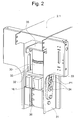
- FIG. 2 shows the left-hand safety device shown in FIG. 1 16.1 with buffer 30.
- the lower yoke 2.1 of the elevator car 2 has a boom 31, on which a carriage 32nd slidably arranged.
- the carriage 32 is arranged along both sides of the boom 31 Linear guides 33, for example by means of bolts 34th guided.
- the Safety gear 16.1 leads the carriage 32 with a Arrow P1 symbolized vertical, or one in Longitudinal direction of the guide rail 7 extending movement out.
- the at the guide leg of the guide rail. 7 jamming safety gear 16.1 causes as a whole the Movement P1.
- the buffer 30 is constructed and is measured that the rebound speed is smaller is the compression speed.
- reusable buffers for example, cellular Polyurethane used.
- Disposable buffers are also possible.
- the safety gear 16,16.1 with buffer and boom can be arranged on the counterweight 4.
- the buffer 30 has a return loss, the causes the Ausfederungs technically is smaller as the compression speed.
- a buffer material can be used that consists of a cellular Polyurethane exists.
- the damping effect arises largely by the energy intake of the warming Air in the polyurethane cells.
- this will Damping effect supported by internal friction of the Polyurethane material and displacement of air bubbles in Material through the porous cell walls.
- the device according to the invention can also be used for to use the catch upwards.
- the safety gear is up and the buffer down arranged.
Landscapes
- Engineering & Computer Science (AREA)
- Mechanical Engineering (AREA)
- Maintenance And Inspection Apparatuses For Elevators (AREA)
- Valve Device For Special Equipments (AREA)
- Forklifts And Lifting Vehicles (AREA)
- Elevator Control (AREA)
Abstract
Description
einen Aufzug mit einem Auslösemechanismus zum Festsetzen einer Aufzugskabine bzw. eines Gegengewichtes im Notfall,
eine Fangvorrichtung mit Puffer als Teil des Auslösemechanismus,
Claims (3)
- Sicherheitseinrichtung für einen Aufzug mit einer in einem Aufzugsschacht (1) verfahrbaren Aufzugskabine (2) und einem im Aufzugsschacht (1) verfahrbaren Gegengewicht (4), wobei ein die Geschwindigkeit der Aufzugskabine (2) bzw. des Gegengewichtes (4) überwachender Geschwindigkeitsbegrenzer (13) vorgesehen ist, der bei Übergeschwindigkeit ein die Aufzugskabine (2) bzw. das Gegengewicht (4) stillsetzende Fangvorrichtung (16,16.1) betätigt,
dadurch gekennzeichnet, dass die Fangvorrichtung (16,16.1) im Auslösefall gegenüber der Aufzugskabine (2) bzw. gegenüber dem Gegengewicht (4) verschiebbar ist, wobei der Weg der Fangvorrichtung (16,16.1) mittels Puffer (30) begrenzbar ist. - Sicherheitseinrichtung nach Anspruch 1,
dadurch gekennzeichnet, dass ein Schlitten (32) und ein Puffer (30) je Fangvorrichtung (16,16.1) vorgesehen ist, wobei im Auslösefall der die Fangvorrichtung (16,16.1) tragende Schlitten (32) gegen den Puffer (30) bewegbar ist. - Sicherheitseinrichtung nach einem der Ansprüche 1 oder 2,
dadurch gekennzeichnet, dass an einem Joch (2.1) der Aufzugskabine (2) bzw. des Gegengewichtes (4) ein Ausleger (31) mit Linearführungen (33) angeordnet ist, entlang denen der Schlitten (32) geführt ist.
Priority Applications (2)
| Application Number | Priority Date | Filing Date | Title |
|---|---|---|---|
| EP05000455A EP1557390B1 (de) | 2004-01-22 | 2005-01-12 | Sicherheitseinrichtung für einen Aufzug |
| ES05000455T ES2305913T3 (es) | 2004-01-22 | 2005-01-12 | Dispositivo de seguridad para un ascensor. |
Applications Claiming Priority (3)
| Application Number | Priority Date | Filing Date | Title |
|---|---|---|---|
| EP04405042 | 2004-01-22 | ||
| EP04405042 | 2004-01-22 | ||
| EP05000455A EP1557390B1 (de) | 2004-01-22 | 2005-01-12 | Sicherheitseinrichtung für einen Aufzug |
Publications (2)
| Publication Number | Publication Date |
|---|---|
| EP1557390A1 true EP1557390A1 (de) | 2005-07-27 |
| EP1557390B1 EP1557390B1 (de) | 2008-05-07 |
Family
ID=34932041
Family Applications (1)
| Application Number | Title | Priority Date | Filing Date |
|---|---|---|---|
| EP05000455A Expired - Lifetime EP1557390B1 (de) | 2004-01-22 | 2005-01-12 | Sicherheitseinrichtung für einen Aufzug |
Country Status (4)
| Country | Link |
|---|---|
| EP (1) | EP1557390B1 (de) |
| AT (1) | ATE394337T1 (de) |
| DE (1) | DE502005003930D1 (de) |
| ES (1) | ES2305913T3 (de) |
Cited By (1)
| Publication number | Priority date | Publication date | Assignee | Title |
|---|---|---|---|---|
| DE102008016141A1 (de) * | 2008-03-28 | 2009-11-05 | Riedl Aufzugbau Gmbh & Co. Kg | Aufzug mit platzsparender Spanngewichtanordnung |
Citations (4)
| Publication number | Priority date | Publication date | Assignee | Title |
|---|---|---|---|---|
| US4819765A (en) * | 1986-05-06 | 1989-04-11 | Kone Elevator Gmbh | Arrester device for elevators |
| EP0432634A2 (de) * | 1989-12-14 | 1991-06-19 | KONE Elevator GmbH | Fangvorrichtung |
| EP0957059A2 (de) * | 1998-05-13 | 1999-11-17 | ORONA S. Coop. | Sicherheitsbremsfangvorrichtung für einen Aufzug |
| EP0968954A1 (de) * | 1998-07-03 | 2000-01-05 | Cobianchi Liftteile Ag | Bremsfangvorrichtung, insbesondere für Aufzugskabinen |
-
2005
- 2005-01-12 AT AT05000455T patent/ATE394337T1/de not_active IP Right Cessation
- 2005-01-12 EP EP05000455A patent/EP1557390B1/de not_active Expired - Lifetime
- 2005-01-12 DE DE502005003930T patent/DE502005003930D1/de not_active Expired - Lifetime
- 2005-01-12 ES ES05000455T patent/ES2305913T3/es not_active Expired - Lifetime
Patent Citations (4)
| Publication number | Priority date | Publication date | Assignee | Title |
|---|---|---|---|---|
| US4819765A (en) * | 1986-05-06 | 1989-04-11 | Kone Elevator Gmbh | Arrester device for elevators |
| EP0432634A2 (de) * | 1989-12-14 | 1991-06-19 | KONE Elevator GmbH | Fangvorrichtung |
| EP0957059A2 (de) * | 1998-05-13 | 1999-11-17 | ORONA S. Coop. | Sicherheitsbremsfangvorrichtung für einen Aufzug |
| EP0968954A1 (de) * | 1998-07-03 | 2000-01-05 | Cobianchi Liftteile Ag | Bremsfangvorrichtung, insbesondere für Aufzugskabinen |
Cited By (1)
| Publication number | Priority date | Publication date | Assignee | Title |
|---|---|---|---|---|
| DE102008016141A1 (de) * | 2008-03-28 | 2009-11-05 | Riedl Aufzugbau Gmbh & Co. Kg | Aufzug mit platzsparender Spanngewichtanordnung |
Also Published As
| Publication number | Publication date |
|---|---|
| EP1557390B1 (de) | 2008-05-07 |
| ATE394337T1 (de) | 2008-05-15 |
| DE502005003930D1 (de) | 2008-06-19 |
| ES2305913T3 (es) | 2008-11-01 |
Similar Documents
| Publication | Publication Date | Title |
|---|---|---|
| WO2015150285A1 (de) | Aufzug mit einer bremsvorrichtung | |
| EP1270487B1 (de) | Verfahren und Einrichtung zur Evakuation von Aufzugspassagieren | |
| DE102007015277A1 (de) | Aufzugsanlage mit einer Aufzugskabinenbremseinrichtung und Verfahren zum Bremsen einer Aufzugskabine | |
| DE112014006564T5 (de) | Aufzugvorrichtung | |
| EP1067084A1 (de) | Vorrichtung und Verfahren zur Verhinderung von Vertikalverschiebungen und Vertikalschwingungen an Lastaufnahmemitteln von Vertikalförderanlagen | |
| EP2125389A1 (de) | Aufzug | |
| EP1588977B1 (de) | Einrichtung zur Feinpositionierung der Kabinen einer Mehrdeckkabine für einen Aufzug | |
| EP2219983A1 (de) | Auffahrbremse für zwei unabhängig voneinander verfahrende aufzugkörper | |
| WO2012110273A1 (de) | Reibungsbremse für aufzüge mit verbesserten dämpfungseigenschaften | |
| EP1853504B1 (de) | Brems- bzw. fangeinrichtung für eine aufzugskabine | |
| WO2015144686A1 (de) | Bremseinrichtung für einen fahrkorb einer aufzuganlage | |
| DE112013006610B4 (de) | Aufzugsvorrichtung | |
| DE102012109969A1 (de) | Bremseinrichtung für einen Aufzug | |
| EP2512969B1 (de) | Aufzuganlage mit doppeldecker | |
| WO2010072657A1 (de) | Gegengewicht in einer aufzugsanlage | |
| DE112015004314B4 (de) | Aufzugvorrichtungen | |
| EP1557390B1 (de) | Sicherheitseinrichtung für einen Aufzug | |
| DE102008049379A1 (de) | Notbefreiungssystem für Aufzüge | |
| WO2018054927A1 (de) | Aufzugsanlage mit einer kabine umfassend eine auffangeinrichtung | |
| EP0873963A1 (de) | Linearantrieb für eine Transporteinrichtung | |
| DE19712646A1 (de) | Seilaufzug | |
| WO2016005429A1 (de) | Aufzugsanlage mit bremseinrichtung am fahrkorb und verfahren zum betrieb der selbigen | |
| EP1447369B1 (de) | Einrichtung zum Einrücken einer Fangvorrichtung für eine Aufzugskabine | |
| DE102016125559A1 (de) | Aufzug und verfahren zum betreiben eines aufzugs | |
| DE102011001449A1 (de) | Sicherheitsfangvorrichtung für eine Aufzugsanlage sowie Verfahren zur Sicherung einer schienengeführten Aufzugskabine einer Aufzugsanlage |
Legal Events
| Date | Code | Title | Description |
|---|---|---|---|
| PUAI | Public reference made under article 153(3) epc to a published international application that has entered the european phase |
Free format text: ORIGINAL CODE: 0009012 |
|
| AK | Designated contracting states |
Kind code of ref document: A1 Designated state(s): AT BE BG CH CY CZ DE DK EE ES FI FR GB GR HU IE IS IT LI LT LU MC NL PL PT RO SE SI SK TR |
|
| AX | Request for extension of the european patent |
Extension state: AL BA HR LV MK YU |
|
| 17P | Request for examination filed |
Effective date: 20060109 |
|
| AKX | Designation fees paid |
Designated state(s): AT BE BG CH CY CZ DE DK EE ES FI FR GB GR HU IE IS IT LI LT LU MC NL PL PT RO SE SI SK TR |
|
| 17Q | First examination report despatched |
Effective date: 20061013 |
|
| GRAP | Despatch of communication of intention to grant a patent |
Free format text: ORIGINAL CODE: EPIDOSNIGR1 |
|
| GRAS | Grant fee paid |
Free format text: ORIGINAL CODE: EPIDOSNIGR3 |
|
| GRAA | (expected) grant |
Free format text: ORIGINAL CODE: 0009210 |
|
| AK | Designated contracting states |
Kind code of ref document: B1 Designated state(s): AT BE BG CH CY CZ DE DK EE ES FI FR GB GR HU IE IS IT LI LT LU MC NL PL PT RO SE SI SK TR |
|
| REG | Reference to a national code |
Ref country code: GB Ref legal event code: FG4D Free format text: NOT ENGLISH |
|
| REG | Reference to a national code |
Ref country code: CH Ref legal event code: EP |
|
| REG | Reference to a national code |
Ref country code: IE Ref legal event code: FG4D Free format text: LANGUAGE OF EP DOCUMENT: GERMAN |
|
| REF | Corresponds to: |
Ref document number: 502005003930 Country of ref document: DE Date of ref document: 20080619 Kind code of ref document: P |
|
| PG25 | Lapsed in a contracting state [announced via postgrant information from national office to epo] |
Ref country code: SI Free format text: LAPSE BECAUSE OF FAILURE TO SUBMIT A TRANSLATION OF THE DESCRIPTION OR TO PAY THE FEE WITHIN THE PRESCRIBED TIME-LIMIT Effective date: 20080507 |
|
| PG25 | Lapsed in a contracting state [announced via postgrant information from national office to epo] |
Ref country code: NL Free format text: LAPSE BECAUSE OF FAILURE TO SUBMIT A TRANSLATION OF THE DESCRIPTION OR TO PAY THE FEE WITHIN THE PRESCRIBED TIME-LIMIT Effective date: 20080507 |
|
| REG | Reference to a national code |
Ref country code: ES Ref legal event code: FG2A Ref document number: 2305913 Country of ref document: ES Kind code of ref document: T3 |
|
| NLV1 | Nl: lapsed or annulled due to failure to fulfill the requirements of art. 29p and 29m of the patents act | ||
| PG25 | Lapsed in a contracting state [announced via postgrant information from national office to epo] |
Ref country code: PL Free format text: LAPSE BECAUSE OF FAILURE TO SUBMIT A TRANSLATION OF THE DESCRIPTION OR TO PAY THE FEE WITHIN THE PRESCRIBED TIME-LIMIT Effective date: 20080507 |
|
| REG | Reference to a national code |
Ref country code: IE Ref legal event code: FD4D |
|
| PG25 | Lapsed in a contracting state [announced via postgrant information from national office to epo] |
Ref country code: IS Free format text: LAPSE BECAUSE OF FAILURE TO SUBMIT A TRANSLATION OF THE DESCRIPTION OR TO PAY THE FEE WITHIN THE PRESCRIBED TIME-LIMIT Effective date: 20080907 |
|
| PG25 | Lapsed in a contracting state [announced via postgrant information from national office to epo] |
Ref country code: PT Free format text: LAPSE BECAUSE OF FAILURE TO SUBMIT A TRANSLATION OF THE DESCRIPTION OR TO PAY THE FEE WITHIN THE PRESCRIBED TIME-LIMIT Effective date: 20081007 Ref country code: LT Free format text: LAPSE BECAUSE OF FAILURE TO SUBMIT A TRANSLATION OF THE DESCRIPTION OR TO PAY THE FEE WITHIN THE PRESCRIBED TIME-LIMIT Effective date: 20080507 Ref country code: IE Free format text: LAPSE BECAUSE OF FAILURE TO SUBMIT A TRANSLATION OF THE DESCRIPTION OR TO PAY THE FEE WITHIN THE PRESCRIBED TIME-LIMIT Effective date: 20080507 Ref country code: DK Free format text: LAPSE BECAUSE OF FAILURE TO SUBMIT A TRANSLATION OF THE DESCRIPTION OR TO PAY THE FEE WITHIN THE PRESCRIBED TIME-LIMIT Effective date: 20080507 Ref country code: CZ Free format text: LAPSE BECAUSE OF FAILURE TO SUBMIT A TRANSLATION OF THE DESCRIPTION OR TO PAY THE FEE WITHIN THE PRESCRIBED TIME-LIMIT Effective date: 20080507 Ref country code: SE Free format text: LAPSE BECAUSE OF FAILURE TO SUBMIT A TRANSLATION OF THE DESCRIPTION OR TO PAY THE FEE WITHIN THE PRESCRIBED TIME-LIMIT Effective date: 20080807 |
|
| PG25 | Lapsed in a contracting state [announced via postgrant information from national office to epo] |
Ref country code: RO Free format text: LAPSE BECAUSE OF FAILURE TO SUBMIT A TRANSLATION OF THE DESCRIPTION OR TO PAY THE FEE WITHIN THE PRESCRIBED TIME-LIMIT Effective date: 20080507 Ref country code: SK Free format text: LAPSE BECAUSE OF FAILURE TO SUBMIT A TRANSLATION OF THE DESCRIPTION OR TO PAY THE FEE WITHIN THE PRESCRIBED TIME-LIMIT Effective date: 20080507 |
|
| PLBE | No opposition filed within time limit |
Free format text: ORIGINAL CODE: 0009261 |
|
| STAA | Information on the status of an ep patent application or granted ep patent |
Free format text: STATUS: NO OPPOSITION FILED WITHIN TIME LIMIT |
|
| 26N | No opposition filed |
Effective date: 20090210 |
|
| PG25 | Lapsed in a contracting state [announced via postgrant information from national office to epo] |
Ref country code: EE Free format text: LAPSE BECAUSE OF FAILURE TO SUBMIT A TRANSLATION OF THE DESCRIPTION OR TO PAY THE FEE WITHIN THE PRESCRIBED TIME-LIMIT Effective date: 20080507 Ref country code: BG Free format text: LAPSE BECAUSE OF FAILURE TO SUBMIT A TRANSLATION OF THE DESCRIPTION OR TO PAY THE FEE WITHIN THE PRESCRIBED TIME-LIMIT Effective date: 20080807 |
|
| PG25 | Lapsed in a contracting state [announced via postgrant information from national office to epo] |
Ref country code: MC Free format text: LAPSE BECAUSE OF NON-PAYMENT OF DUE FEES Effective date: 20090131 |
|
| PG25 | Lapsed in a contracting state [announced via postgrant information from national office to epo] |
Ref country code: BE Free format text: LAPSE BECAUSE OF NON-PAYMENT OF DUE FEES Effective date: 20090131 |
|
| PG25 | Lapsed in a contracting state [announced via postgrant information from national office to epo] |
Ref country code: AT Free format text: LAPSE BECAUSE OF NON-PAYMENT OF DUE FEES Effective date: 20090112 |
|
| PG25 | Lapsed in a contracting state [announced via postgrant information from national office to epo] |
Ref country code: GR Free format text: LAPSE BECAUSE OF FAILURE TO SUBMIT A TRANSLATION OF THE DESCRIPTION OR TO PAY THE FEE WITHIN THE PRESCRIBED TIME-LIMIT Effective date: 20080808 |
|
| PG25 | Lapsed in a contracting state [announced via postgrant information from national office to epo] |
Ref country code: LU Free format text: LAPSE BECAUSE OF NON-PAYMENT OF DUE FEES Effective date: 20090112 |
|
| PG25 | Lapsed in a contracting state [announced via postgrant information from national office to epo] |
Ref country code: HU Free format text: LAPSE BECAUSE OF FAILURE TO SUBMIT A TRANSLATION OF THE DESCRIPTION OR TO PAY THE FEE WITHIN THE PRESCRIBED TIME-LIMIT Effective date: 20081108 |
|
| PG25 | Lapsed in a contracting state [announced via postgrant information from national office to epo] |
Ref country code: TR Free format text: LAPSE BECAUSE OF FAILURE TO SUBMIT A TRANSLATION OF THE DESCRIPTION OR TO PAY THE FEE WITHIN THE PRESCRIBED TIME-LIMIT Effective date: 20080507 |
|
| PG25 | Lapsed in a contracting state [announced via postgrant information from national office to epo] |
Ref country code: CY Free format text: LAPSE BECAUSE OF FAILURE TO SUBMIT A TRANSLATION OF THE DESCRIPTION OR TO PAY THE FEE WITHIN THE PRESCRIBED TIME-LIMIT Effective date: 20080507 |
|
| REG | Reference to a national code |
Ref country code: FR Ref legal event code: PLFP Year of fee payment: 12 |
|
| PGFP | Annual fee paid to national office [announced via postgrant information from national office to epo] |
Ref country code: FI Payment date: 20160113 Year of fee payment: 12 Ref country code: GB Payment date: 20160120 Year of fee payment: 12 |
|
| REG | Reference to a national code |
Ref country code: FR Ref legal event code: PLFP Year of fee payment: 13 |
|
| PGFP | Annual fee paid to national office [announced via postgrant information from national office to epo] |
Ref country code: CH Payment date: 20170130 Year of fee payment: 13 Ref country code: FR Payment date: 20170120 Year of fee payment: 13 Ref country code: DE Payment date: 20170120 Year of fee payment: 13 |
|
| PGFP | Annual fee paid to national office [announced via postgrant information from national office to epo] |
Ref country code: ES Payment date: 20170113 Year of fee payment: 13 Ref country code: IT Payment date: 20170124 Year of fee payment: 13 |
|
| GBPC | Gb: european patent ceased through non-payment of renewal fee |
Effective date: 20170112 |
|
| PG25 | Lapsed in a contracting state [announced via postgrant information from national office to epo] |
Ref country code: FI Free format text: LAPSE BECAUSE OF NON-PAYMENT OF DUE FEES Effective date: 20170112 |
|
| PG25 | Lapsed in a contracting state [announced via postgrant information from national office to epo] |
Ref country code: GB Free format text: LAPSE BECAUSE OF NON-PAYMENT OF DUE FEES Effective date: 20170112 |
|
| REG | Reference to a national code |
Ref country code: DE Ref legal event code: R119 Ref document number: 502005003930 Country of ref document: DE |
|
| REG | Reference to a national code |
Ref country code: CH Ref legal event code: PL |
|
| PG25 | Lapsed in a contracting state [announced via postgrant information from national office to epo] |
Ref country code: DE Free format text: LAPSE BECAUSE OF NON-PAYMENT OF DUE FEES Effective date: 20180801 Ref country code: FR Free format text: LAPSE BECAUSE OF NON-PAYMENT OF DUE FEES Effective date: 20180131 |
|
| REG | Reference to a national code |
Ref country code: FR Ref legal event code: ST Effective date: 20180928 |
|
| PG25 | Lapsed in a contracting state [announced via postgrant information from national office to epo] |
Ref country code: CH Free format text: LAPSE BECAUSE OF NON-PAYMENT OF DUE FEES Effective date: 20180131 Ref country code: LI Free format text: LAPSE BECAUSE OF NON-PAYMENT OF DUE FEES Effective date: 20180131 |
|
| PG25 | Lapsed in a contracting state [announced via postgrant information from national office to epo] |
Ref country code: IT Free format text: LAPSE BECAUSE OF NON-PAYMENT OF DUE FEES Effective date: 20180112 |
|
| REG | Reference to a national code |
Ref country code: ES Ref legal event code: FD2A Effective date: 20190730 |
|
| PG25 | Lapsed in a contracting state [announced via postgrant information from national office to epo] |
Ref country code: ES Free format text: LAPSE BECAUSE OF NON-PAYMENT OF DUE FEES Effective date: 20180113 |