EP1557371B1 - Kit mit zwei Behältern und einem Applikator - Google Patents
Kit mit zwei Behältern und einem Applikator Download PDFInfo
- Publication number
- EP1557371B1 EP1557371B1 EP05300029A EP05300029A EP1557371B1 EP 1557371 B1 EP1557371 B1 EP 1557371B1 EP 05300029 A EP05300029 A EP 05300029A EP 05300029 A EP05300029 A EP 05300029A EP 1557371 B1 EP1557371 B1 EP 1557371B1
- Authority
- EP
- European Patent Office
- Prior art keywords
- applicator
- kit according
- substance
- receptacle
- container
- Prior art date
- Legal status (The legal status is an assumption and is not a legal conclusion. Google has not performed a legal analysis and makes no representation as to the accuracy of the status listed.)
- Expired - Lifetime
Links
Images


Classifications
-
- B—PERFORMING OPERATIONS; TRANSPORTING
- B65—CONVEYING; PACKING; STORING; HANDLING THIN OR FILAMENTARY MATERIAL
- B65D—CONTAINERS FOR STORAGE OR TRANSPORT OF ARTICLES OR MATERIALS, e.g. BAGS, BARRELS, BOTTLES, BOXES, CANS, CARTONS, CRATES, DRUMS, JARS, TANKS, HOPPERS, FORWARDING CONTAINERS; ACCESSORIES, CLOSURES, OR FITTINGS THEREFOR; PACKAGING ELEMENTS; PACKAGES
- B65D81/00—Containers, packaging elements, or packages, for contents presenting particular transport or storage problems, or adapted to be used for non-packaging purposes after removal of contents
- B65D81/32—Containers, packaging elements, or packages, for contents presenting particular transport or storage problems, or adapted to be used for non-packaging purposes after removal of contents for packaging two or more different materials which must be maintained separate prior to use in admixture
- B65D81/3205—Separate rigid or semi-rigid containers joined to each other at their external surfaces
- B65D81/3211—Separate rigid or semi-rigid containers joined to each other at their external surfaces coaxially and provided with means facilitating admixture
-
- B—PERFORMING OPERATIONS; TRANSPORTING
- B65—CONVEYING; PACKING; STORING; HANDLING THIN OR FILAMENTARY MATERIAL
- B65D—CONTAINERS FOR STORAGE OR TRANSPORT OF ARTICLES OR MATERIALS, e.g. BAGS, BARRELS, BOTTLES, BOXES, CANS, CARTONS, CRATES, DRUMS, JARS, TANKS, HOPPERS, FORWARDING CONTAINERS; ACCESSORIES, CLOSURES, OR FITTINGS THEREFOR; PACKAGING ELEMENTS; PACKAGES
- B65D51/00—Closures not otherwise provided for
- B65D51/24—Closures not otherwise provided for combined or co-operating with auxiliary devices for non-closing purposes
- B65D51/32—Closures not otherwise provided for combined or co-operating with auxiliary devices for non-closing purposes with brushes or rods for applying or stirring contents
Definitions
- the present invention relates to devices for packaging and applying a liquid product, for example a product for coloring the hair resulting from the mixing of a first and a second substance packaged separately.
- Japanese Patent JP 2002-179118 discloses a packaging and application device comprising an applicator and a container in which is disposed a cap separating two compartments for storing two substances to be mixed extemporaneously.
- the cap can be moved out of a closed position when mixing the two substances.
- Such a device has a relatively complex structure.
- US Patent 4,573,506 discloses other devices for separately conditioning two products to be mixed extemporaneously. These devices are not intended for use in cosmetics of the mixture, for example on the hair.
- the PAVENIK patent US 5,307,847 a A subject of the invention is an applicator comprising a bottle containing a product and a deformable cap.
- the cap defines a compartment for receiving a supply of product through a closable orifice allowing it to communicate with the bottle when the orifice is open.
- An applicator element is attached to the end of a hollow rod connected to the cap compartment, so that the applicator element can be supplied with product during the application, when the cap is separated from the cap. bottle.
- the application element is a brush or a foam.
- the stem channel can not be closed.
- the international application DORR WO 03/059118 relates to a cleaning device comprising a container containing a product to be applied, a tube placed at the outlet of the container and a brush formed of a metal support fixed in the tube and maintaining bristles.
- the bristles are not monolithically molded with the applicator, and the applicator can not take a shutter configuration.
- the invention makes it possible to use, for applying the mixture, the assembly formed by one of the containers and the applicator, this assembly having a reduced weight relative to the total weight of the kit.
- the kit is relatively simple to manufacture and use.
- the first substance may be in particular a hair dye.
- the second substance can be a hair coloring oxidant.
- the container intended to be connected to the applicator during the application is preferably made with a flexible, elastically deformable wall, which allows the user to create inside it an overpressure to expel out of the container the product contained inside or to collect the mixture between two uses.
- the two containers may, where appropriate, each comprise a flexible wall, elastically deformable.
- the applicator can be made with different shapes, depending on the intended application.
- the applicator may comprise an application part made with at least one relief, for example a succession of teeth or bristles.
- the aforementioned channel of the applicator can lead to one end of the elongated portion.
- this channel can lead to at least one lateral orifice of the application part, this lateral orifice being for example located between two teeth or bristles when the application part comprises at least one succession of teeth or bristles allowing to comb the hair.
- the applicator may comprise at least one sealing member configured to apply sealingly to at least one of the containers.
- At least one of the containers may comprise a neck and the applicator may comprise at least one sealing lip arranged to be applied on the radially inner surface of this neck.
- the applicator can thus be fixed in an unsealed manner on the container in which the elongate portion extends.
- the applicator may comprise, where appropriate, a sealing surface formed for example by a portion of the elongated portion of the applicator, this portion being arranged to be applied on an inner surface of the container to the inside which the elongated part extends.
- the applicator may comprise a first tubular skirt, threaded internally, arranged to receive the first container and a second tubular skirt, threaded internally, arranged to receive the second container.
- the applicator channel through which the substance contained in one of the containers can reach the other container, can be made with an inner section sufficiently small to prevent leakage of this substance when the assembly constituted by the applicator and one of the containers is not yet mounted on the other container.
- the applicator channel may be closed at one end by closure means arranged to move from a closure configuration to an open configuration allowing the two containers to communicate with each other in response to an action exerted by the user.
- the closure means may be configured to change configuration by bearing against the bottom of the first container when the applicator is engaged therein.
- the closure means may comprise a pin connected to the elongate portion of the applicator by a frangible zone.
- the sealing means can be made monolithically by molding plastic material with the applicator.
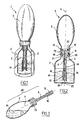
- the device 1 for packaging and application represented in the Figures 1 and 2 comprises a first container 2, a second container 3 superimposed on the first along a longitudinal axis X and an applicator 4 having an inner channel 5 through which the two containers 2 and 3 can communicate.
- the device 1 comes from the assembly of the kit represented in FIG. figure 4 , wherein the first container 2, which contains a first substance A, is closed by an individual cap 8.
- the second container 3, which contains a second substance B, is also closed by an individual cap 7.
- the applicator 4 can be initially separated from containers 2 and 3, as seen on figure 4 .
- the individual plugs 7 and 8 each comprise an internally threaded mounting skirt 9 and a sealing lip 10. This is arranged to seal on the radially inner surface of the neck 11 of the container 2 with respect to the plug 8 and the neck 12 of the container 3 with respect to the plug 7.
- the substance A is for example a coloring oxidant and the substance B a dye intended to be mixed with the substance A at the time of use.
- the second container 3 comprises a flexible wall, elastically deformable, on which the user can press to reduce its internal volume.
- the applicator 4 comprises an elongated portion 14 of axis X, provided with an enlarged portion 20 which is connected to a coupling portion 13, which makes it possible to secure the receptacles 2 and 3.
- the elongate portion 14 has a lower portion 15.
- the latter has for example, as illustrated, reliefs 16 made monolithically with the elongate portion 14.
- the reliefs 16 are constituted for example by a succession of teeth.
- the coupling portion 13 comprises a first tubular skirt 18 of axis X, threaded internally, arranged to screw on the neck 11 of the first container 2 and a second tubular skirt 19 of axis X also, arranged to screw on the neck 12 of the second container 3.
- the skirts 18 and 19 may, where appropriate, have different inside diameters, in order to avoid the risk of inverting containers 2 and 3 during the assembly of the device 1.
- the coupling part 13 also comprises sealing for sealing its fastening on the container 3.
- sealing means consist, in the example considered, by an annular sealing lip 22 arranged to be applied on the inner surface of the neck 12.
- the outer surface 21 of the widened portion is sealingly applied to the lower surface of the neck 11.
- the channel 5 opens at the lower end of the elongated portion 14 through an orifice 25, which may be located for example at a distance relatively close to the bottom 26 of the first container 2, as seen on the figure 2 .
- the section of the channel 5 is small enough to avoid a significant leakage of the substance A during this operation, better avoid any flow.
- the user can then press several times the flexible wall of the container 3 to expel the substance A contained inside the first container 2 and stir the resulting mixture. Whenever the user stops exerting pressure on the wall of the second container 3, it resumes elastically its initial shape.
- the presence of the reliefs 16 may contribute to the homogenization of the mixture M under the effect of the turbulence created in the first container 2 by the variation of the internal volume of the second container 3.
- the non-completely airtight fastening of the skirt 18 on the neck 11 and the clearance between the enlarged portion 20 and the neck 11 can facilitate the departure of the air contained in the container 2 during its filling by the substance contained in the container 3.
- the mixture M can be dispensed by again separating the assembly 30 from the first container 2, as illustrated in FIG. figure 3 .
- the container 3 then serves as a gripping member.
- the mixture M can be applied to the hair by pressing the wall of the second container 3 and the reliefs 16 can be used to distribute the product on the hair, the hair being engageable between them.
- the kit may comprise a plug 33 arranged to attach to the skirt 19 of the applicator 4, the latter being proposed to the user already in place on the first container 2.
- the plug 33 may comprise a central shutter 34 arranged for close the channel 5 of the applicator.
- the user can for example remove the plugs 7 and 33 and then screw the skirt 19 on the neck 12 of the second container 3.
- the kit may also include, as illustrated in figure 7 , a shutter 36 fixed to the end of the elongated portion 14 of the applicator 4 to close the channel 5.
- the applicator 4 can be proposed to the user already in place on the first container 2.
- the user can remove the cap 7 and screw the skirt 19 on the neck 12 of the second container 3.
- the shutter 36 is still in place at the end of the applicator 4, which prevents any risk of flow of the substance A out of the first container 2.
- the user can exert pressure on the wall of the second container 3 to cause the expulsion of the shutter 36 and allow the substances A and B to mix.
- the kit comprises the container 2 containing the substance A, closed by the cap 8, and the container 3 containing the substance B, closed by the applicator 4, the latter being provided at its free end with a sealing means 40 that was also represented at the figure 9 .
- This sealing means 40 comprises, for example, as illustrated, a cap comprising a pin 21 connected by a preferential annular zone of rupture 42 to a flange 43 projecting radially inwards at one end of the channel 5.
- the cap is advantageously made monolithically with the elongated portion 14 of the applicator 4, by plastic molding.
- the closure means 40 are arranged to automatically switch from a closure configuration to an open configuration allowing the substance B to mix with the substance A, when the elongated portion 14 of the applicator 4 is introduced into the container 2.
- This configuration change can be obtained for example by cooperation between the closure means 40 and the bottom of the container 2 in which the applicator 4 is introduced.
- the pin 41 thus bears against the bottom of the container 2 before the end of the screwing of the skirt 18 on the neck 11 of the container 2 and the annular zone 42 breakable breaks, which has the consequence that at the end of the screwing of the applicator, the pin 41 is raised in the channel 5.
- the diameter of the annular zone 42 is preferably clearly less than the inside diameter of the channel 5.
- shutter means 40 could be made otherwise.
- the closure means 40 comprise a shutter attached to the elongated portion 14 of the applicator 4 and held thereon, for example by snapping, friction, gluing or welding.
- the shutter is for example a heat-sealed cover at the end of the elongated portion 14 that the user can remove or drill before the introduction of the applicator 4 in the container 2. If necessary, the bottom of the latter could be provided with a pin that would perforate the aforementioned operculum.
- the channel 5 opens through lateral orifices 38 between the reliefs 16.
- These may for example be constituted by a succession of teeth or bristles, each of these reliefs extending on the outer periphery of the elongate portion.
- outer periphery is meant a region of the elongate portion extending about the X axis.
- the reliefs 16, particularly the teeth or bristles, may each extend in a direction substantially perpendicular to the longitudinal axis X.
- All orifices 38 may open, if necessary, on the same side of the applicator.
- the reliefs 16 may possibly not be made in one piece with the elongated portion 14 by molding of material.
Landscapes
- Engineering & Computer Science (AREA)
- Mechanical Engineering (AREA)
- Containers And Packaging Bodies Having A Special Means To Remove Contents (AREA)
- Closures For Containers (AREA)
- Coating Apparatus (AREA)
- Package Specialized In Special Use (AREA)
Claims (18)
- Kit zur Vorbereitung und zum Applizieren, das aufweist:- einen ersten Behälter (2), der eine erste Substanz (A) enthält,- einen zweiten Behälter (3), der eine zweite Substanz (B) enthält, die von der ersten Substanz verschieden ist,- eine Applikationseinrichtung (4), mit der die zwei Behälter (2, 3) mit einander zu einem Stück verbunden werden können, wobei diese Applikationseinrichtung zumindest ein längserstrecktes Teil (14) aufweist, das in einen der Behälter einzugreifen vermag und durch einen Kanal (5) durchquert wird, durch welchen die Substanz (B), die in dem einen der Behälter enthalten ist, zirkulieren kann, um sich mit der Substanz (A), die in dem anderen Behälter enthalten ist, zu vermischen, wobei die erste Substanz eine Flüssigkeit oder ein Pulver ist, und die zweite Substanz eine Flüssigkeit ist.
- Kit nach Anspruch 1, das aufweist:- Verschlüsse (7, 8), die angeordnet sind, um den ersten und den zweiten Behälter in Abwesenheit der Applikationseinrichtung (4) in einer dichten Weise zu verschließen.
- Kit nach dem Anspruch 1 oder 2:- wobei die Applikationseinrichtung (4) zumindest eine Folge von Strukturen (16) bzw. Reliefs auf seinem äußeren Umfang, insbesondere zumindest eine Folge von Zahnungen oder Noppen aufweist, die durch Formung aus einem Material in einer monolithischen Weise mit der Applikationseinrichtung (4) ausgebildet sind.
- Kit nach irgendeinem der voranstehenden Ansprüche, wobei der Kanal (5) an einem Ende durch Verschlussmittel (40) verschlossen ist, die angeordnet sind, um in einer Anordnung des Verschlusses eine offene Anordnung zu ermöglichen, die es den zwei Behältern ermöglicht, miteinander in Verbindung zu treten, in Reaktion auf eine Tätigkeit, die von dem Benutzer ausgeübt wird.
- Kit nach dem Anspruch 1, dadurch gekennzeichnet, dass die erste Substanz (A) eine Flüssigkeit ist, insbesondere eine kapillare Farbe.
- Kit nach dem Anspruch 1, dadurch gekennzeichnet, dass die zweite Substanz (B) ein Oxidationsmittel einer kapillaren Färbung ist.
- Kit nach irgendeinem der Ansprüche 1 bis 6, dass zumindest einer der zwei Behälter mit einer flexiblen Seitenwand bzw. Wand, die elastisch verformbar ist, ausgebildet ist.
- Kit nach Anspruch 7, dadurch gekennzeichnet, dass zumindest der Behälter (3), der aus einem Stück mit der Applikationseinrichtung (4) ist, während des Applizierens der Mischung (M), welcher eine flexible Seitenwand bzw. Wand vorzuweisen hat, elastisch verformbar ist.
- Kit nach irgendeinem der voranstehenden Ansprüche, dadurch gekennzeichnet, dass die zwei Behälter (2, 3) jeweils eine flexible Seitenwand bzw. Wand, die elastisch verformbar ist, aufweisen.
- Kit nach dem Anspruch 1, dadurch gekennzeichnet, dass die Applikationseinrichtung (4) einen Applizierabschnitt aufweist, der mit zumindest einer Struktur bzw. einem Relief (16) verwirklicht ist, insbesondere einer Folge von Zahnungen oder Noppen.
- Kit nach dem Anspruch 1, dadurch gekennzeichnet, dass der Kanal (5) an einem Ende des längserstreckten Teils (14) mündet.
- Kit nach dem Anspruch 1, dadurch gekennzeichnet, dass der Kanal (5) außerhalb über zumindest eine Längsöffnung (38), insbesondere zumindest eine Längsöffnung (38), die zwischen zwei Zahnungen oder Warzen bzw. Noppen (16) angeordnet ist, mündet.
- Kit nach irgendeinem der Ansprüche 1 bis 12, dadurch gekennzeichnet, dass die Applikationseinrichtung (4) zumindest ein Dichtelement (20; 22) aufweist, das ausgebildet ist, um in dichtender Weise auf dem einen der Behälter zur Anwendung zu kommen.
- Kit nach dem Anspruch 13, dadurch gekennzeichnet, dass die Applikationseinrichtung (4) angeordnet ist, um in einer vollständig dichten Weise gegenüber der Luft auf dem Behälter, in den sich das längserstreckte Teil (14) erstreckt, festgelegt werden zu können.
- Kit nach irgendeinem der Ansprüche 1 bis 14, dadurch gekennzeichnet, dass die Applikationseinrichtung (4) eine erste rohrförmige Zylinderfläche (18), die innen mit einem Gewinde versehen ist, die angeordnet ist, um den ersten Behälter (2) aufzunehmen, und eine zweite rohrförmige Zylinderfläche (19) aufweist, die im inneren mit einem Gewinde versehen ist, die angeordnet ist, um den zweiten Behälter (2) aufzunehmen.
- Kit nach dem Anspruch 4, dadurch gekennzeichnet, dass die Dichtungsmittel (40) ausgebildet sind, um die Anordnung zu ändern, um in Anlage gegen den Boden des ersten Behälters (2) zu gelangen, wenn die Applikationseinrichtung (4) in diesen eingegriffen hat.
- Kit nach dem Anspruch 16, dadurch gekennzeichnet, dass die Dichtungsmittel eine Punkturspitze bzw. -nadel (41) aufweisen, die an das längserstreckte Teil (14) über einen zerbrechlichen Bereich (42) anschließt.
- Kit nach irgendeinem der Ansprüche 16 und 17, dadurch gekennzeichnet, dass die Dichtungsmittel (40) in einer einstückigen Weise mit der Applikationseinrichtung durch Formung aus Material verwirklicht sind.
Applications Claiming Priority (2)
| Application Number | Priority Date | Filing Date | Title |
|---|---|---|---|
| FR0450104A FR2865196B1 (fr) | 2004-01-20 | 2004-01-20 | Kit comportant deux recipients et un applicateur |
| FR0450104 | 2004-01-20 |
Publications (2)
| Publication Number | Publication Date |
|---|---|
| EP1557371A1 EP1557371A1 (de) | 2005-07-27 |
| EP1557371B1 true EP1557371B1 (de) | 2010-08-18 |
Family
ID=34630688
Family Applications (1)
| Application Number | Title | Priority Date | Filing Date |
|---|---|---|---|
| EP05300029A Expired - Lifetime EP1557371B1 (de) | 2004-01-20 | 2005-01-12 | Kit mit zwei Behältern und einem Applikator |
Country Status (5)
| Country | Link |
|---|---|
| EP (1) | EP1557371B1 (de) |
| AT (1) | ATE478016T1 (de) |
| DE (1) | DE602005022955D1 (de) |
| ES (1) | ES2350046T3 (de) |
| FR (1) | FR2865196B1 (de) |
Families Citing this family (1)
| Publication number | Priority date | Publication date | Assignee | Title |
|---|---|---|---|---|
| FR2927783A1 (fr) | 2008-02-26 | 2009-08-28 | Oreal | Dispositif de conditionnement et de distribution d'un produit cosmetique |
Family Cites Families (11)
| Publication number | Priority date | Publication date | Assignee | Title |
|---|---|---|---|---|
| FR1043061A (fr) * | 1951-08-27 | 1953-11-05 | Pharma Debarge Lab | Dispositif de conditionnement d'un produit en poudre à mélanger extemeporanément à un liquide |
| US2926374A (en) | 1957-01-23 | 1960-03-01 | Adler Leon | Liquid-brushing device |
| US3178755A (en) | 1963-12-13 | 1965-04-20 | Edward L Kormann | Liquid dispenser and applicator |
| FR2552404B1 (fr) | 1983-09-26 | 1987-12-24 | Merck Sharp & Dohme | Ensemble de preparation et de delivrance d'une solution, bouchon obturateur pour cet ensemble et procede de fabrication de ce bouchon |
| US4690579A (en) | 1985-09-03 | 1987-09-01 | Tuckman Drew E | Brush extension device |
| JPH02179118A (ja) | 1988-12-29 | 1990-07-12 | Fujitsu Ltd | 半導体集積回路 |
| US5307847A (en) * | 1992-09-24 | 1994-05-03 | Stanford Pavenick | Applicator for fluid products |
| US5345981A (en) | 1992-09-24 | 1994-09-13 | Stanford Pavenick | Applicator for fluid products |
| US5540654A (en) | 1994-09-02 | 1996-07-30 | North Carolina State University | Iontophoretic electrode |
| JP2002179118A (ja) | 2000-12-08 | 2002-06-26 | Yoshida Industry Co Ltd | 毛髪梳き具付き二液混合注出容器 |
| FR2834190B1 (fr) * | 2001-12-28 | 2004-09-24 | Philippe Marie Jacques Dorr | Dispositif pour le traitement de surfaces par l'action combinee de frottements mecaniques et de liquides |
-
2004
- 2004-01-20 FR FR0450104A patent/FR2865196B1/fr not_active Expired - Fee Related
-
2005
- 2005-01-12 EP EP05300029A patent/EP1557371B1/de not_active Expired - Lifetime
- 2005-01-12 AT AT05300029T patent/ATE478016T1/de not_active IP Right Cessation
- 2005-01-12 ES ES05300029T patent/ES2350046T3/es not_active Expired - Lifetime
- 2005-01-12 DE DE602005022955T patent/DE602005022955D1/de not_active Expired - Lifetime
Also Published As
| Publication number | Publication date |
|---|---|
| ES2350046T3 (es) | 2011-01-17 |
| DE602005022955D1 (de) | 2010-09-30 |
| FR2865196B1 (fr) | 2008-05-30 |
| FR2865196A1 (fr) | 2005-07-22 |
| ATE478016T1 (de) | 2010-09-15 |
| EP1557371A1 (de) | 2005-07-27 |
Similar Documents
| Publication | Publication Date | Title |
|---|---|---|
| EP1136386B1 (de) | Vorrichtung zum unmittelbaren Vermischen von mindestens zwei Produkten | |
| CA2141967C (fr) | Distributeur a plusieurs compartiments pour le stockage et le melange du contenu | |
| EP0260179B1 (de) | Einheit zu getrennter Aufbewahrung zweier Produkte sowie ihrer gleichzeitigen Verwendung nach Vermischung | |
| EP1557111B1 (de) | Applikator mit einem Auftragselement, welcher mit einem Produktbehälter verbunden ist | |
| EP2990350A1 (de) | Verteilungsvorrichtung | |
| EP0238371B1 (de) | Behälter mit einer viskosen Flüssigkeit, die beim ersten Verbrauch mit einem Zusatz versehen werden kann | |
| FR2810639A1 (fr) | Ensemble pour le melange extemporane de deux produits | |
| EP0572645A1 (de) | Vorrichtung zur mischung von zwei verschiedenen und getrennt aufbewahrten produkten. | |
| EP0790190B1 (de) | Einteiliger Behälter zur getrennten Aufbewahrung und Mischung von mindestens zwei Produkten | |
| CA2299595C (fr) | Conditionnement pour effectuer le melange d'un produit a plusieurs composantes | |
| FR2747106A1 (fr) | Dispositif de conditionnement et d'application d'un produit capillaire | |
| EP0430724A1 (de) | Vorrichtung zum Auftragen von flüssigen oder pastösen Produkten auf eine Fläche | |
| CH629149A5 (fr) | Dispositif d'obturation et de distribution pour un recipient muni d'un goulot. | |
| FR2818964A1 (fr) | Ensemble pour le melange extemporane de deux produits | |
| FR2811639A1 (fr) | Dispositif pour le conditionnement et la distribution d'un produit, notamment un produit capillaire | |
| EP1557371B1 (de) | Kit mit zwei Behältern und einem Applikator | |
| JP5590554B2 (ja) | 塗布容器 | |
| WO2009056736A1 (fr) | Dispositif de delivrance d'un fluide | |
| FR2882505A1 (fr) | Tube distributeur de produits cremeux | |
| FR3042959A1 (fr) | Dispositif de conditionnement pour un produit a distribuer, notamment pour un parfum | |
| FR2867957A1 (fr) | Dispositif de conditionnement et d'application d'un produit, notamment cosmetique | |
| WO1999029584A1 (fr) | Dispositif de sortie pour conteneur de fluide | |
| EP1502872B1 (de) | Vorrichtung mit einem Doppelabgabesystem | |
| FR2713059A1 (fr) | Bouchon obturateur pour récipient contenant un liquide. | |
| EP0908114B1 (de) | Verpackungseinheit zum Aufbewahren und Auftragen eines Produktes, insbesondere eines kosmetischen Produktes |
Legal Events
| Date | Code | Title | Description |
|---|---|---|---|
| PUAI | Public reference made under article 153(3) epc to a published international application that has entered the european phase |
Free format text: ORIGINAL CODE: 0009012 |
|
| 17P | Request for examination filed |
Effective date: 20050112 |
|
| AK | Designated contracting states |
Kind code of ref document: A1 Designated state(s): AT BE BG CH CY CZ DE DK EE ES FI FR GB GR HU IE IS IT LI LT LU MC NL PL PT RO SE SI SK TR |
|
| AX | Request for extension of the european patent |
Extension state: AL BA HR LV MK YU |
|
| AKX | Designation fees paid |
Designated state(s): AT BE BG CH CY CZ DE DK EE ES FI FR GB GR HU IE IS IT LI LT LU MC NL PL PT RO SE SI SK TR |
|
| 17Q | First examination report despatched |
Effective date: 20070711 |
|
| GRAP | Despatch of communication of intention to grant a patent |
Free format text: ORIGINAL CODE: EPIDOSNIGR1 |
|
| GRAS | Grant fee paid |
Free format text: ORIGINAL CODE: EPIDOSNIGR3 |
|
| GRAA | (expected) grant |
Free format text: ORIGINAL CODE: 0009210 |
|
| AK | Designated contracting states |
Kind code of ref document: B1 Designated state(s): AT BE BG CH CY CZ DE DK EE ES FI FR GB GR HU IE IS IT LI LT LU MC NL PL PT RO SE SI SK TR |
|
| REG | Reference to a national code |
Ref country code: GB Ref legal event code: FG4D Free format text: NOT ENGLISH |
|
| REG | Reference to a national code |
Ref country code: CH Ref legal event code: EP |
|
| REG | Reference to a national code |
Ref country code: IE Ref legal event code: FG4D Free format text: LANGUAGE OF EP DOCUMENT: FRENCH |
|
| REF | Corresponds to: |
Ref document number: 602005022955 Country of ref document: DE Date of ref document: 20100930 Kind code of ref document: P |
|
| REG | Reference to a national code |
Ref country code: NL Ref legal event code: VDEP Effective date: 20100818 |
|
| REG | Reference to a national code |
Ref country code: ES Ref legal event code: FG2A Effective date: 20110104 |
|
| LTIE | Lt: invalidation of european patent or patent extension |
Effective date: 20100818 |
|
| PG25 | Lapsed in a contracting state [announced via postgrant information from national office to epo] |
Ref country code: AT Free format text: LAPSE BECAUSE OF FAILURE TO SUBMIT A TRANSLATION OF THE DESCRIPTION OR TO PAY THE FEE WITHIN THE PRESCRIBED TIME-LIMIT Effective date: 20100818 Ref country code: FI Free format text: LAPSE BECAUSE OF FAILURE TO SUBMIT A TRANSLATION OF THE DESCRIPTION OR TO PAY THE FEE WITHIN THE PRESCRIBED TIME-LIMIT Effective date: 20100818 Ref country code: LT Free format text: LAPSE BECAUSE OF FAILURE TO SUBMIT A TRANSLATION OF THE DESCRIPTION OR TO PAY THE FEE WITHIN THE PRESCRIBED TIME-LIMIT Effective date: 20100818 |
|
| PG25 | Lapsed in a contracting state [announced via postgrant information from national office to epo] |
Ref country code: SI Free format text: LAPSE BECAUSE OF FAILURE TO SUBMIT A TRANSLATION OF THE DESCRIPTION OR TO PAY THE FEE WITHIN THE PRESCRIBED TIME-LIMIT Effective date: 20100818 Ref country code: PT Free format text: LAPSE BECAUSE OF FAILURE TO SUBMIT A TRANSLATION OF THE DESCRIPTION OR TO PAY THE FEE WITHIN THE PRESCRIBED TIME-LIMIT Effective date: 20101220 Ref country code: PL Free format text: LAPSE BECAUSE OF FAILURE TO SUBMIT A TRANSLATION OF THE DESCRIPTION OR TO PAY THE FEE WITHIN THE PRESCRIBED TIME-LIMIT Effective date: 20100818 Ref country code: BG Free format text: LAPSE BECAUSE OF FAILURE TO SUBMIT A TRANSLATION OF THE DESCRIPTION OR TO PAY THE FEE WITHIN THE PRESCRIBED TIME-LIMIT Effective date: 20101118 Ref country code: CY Free format text: LAPSE BECAUSE OF FAILURE TO SUBMIT A TRANSLATION OF THE DESCRIPTION OR TO PAY THE FEE WITHIN THE PRESCRIBED TIME-LIMIT Effective date: 20100818 Ref country code: IS Free format text: LAPSE BECAUSE OF FAILURE TO SUBMIT A TRANSLATION OF THE DESCRIPTION OR TO PAY THE FEE WITHIN THE PRESCRIBED TIME-LIMIT Effective date: 20101218 |
|
| REG | Reference to a national code |
Ref country code: IE Ref legal event code: FD4D |
|
| PG25 | Lapsed in a contracting state [announced via postgrant information from national office to epo] |
Ref country code: NL Free format text: LAPSE BECAUSE OF FAILURE TO SUBMIT A TRANSLATION OF THE DESCRIPTION OR TO PAY THE FEE WITHIN THE PRESCRIBED TIME-LIMIT Effective date: 20100818 Ref country code: GR Free format text: LAPSE BECAUSE OF FAILURE TO SUBMIT A TRANSLATION OF THE DESCRIPTION OR TO PAY THE FEE WITHIN THE PRESCRIBED TIME-LIMIT Effective date: 20101119 Ref country code: SE Free format text: LAPSE BECAUSE OF FAILURE TO SUBMIT A TRANSLATION OF THE DESCRIPTION OR TO PAY THE FEE WITHIN THE PRESCRIBED TIME-LIMIT Effective date: 20100818 |
|
| PG25 | Lapsed in a contracting state [announced via postgrant information from national office to epo] |
Ref country code: DK Free format text: LAPSE BECAUSE OF FAILURE TO SUBMIT A TRANSLATION OF THE DESCRIPTION OR TO PAY THE FEE WITHIN THE PRESCRIBED TIME-LIMIT Effective date: 20100818 Ref country code: IE Free format text: LAPSE BECAUSE OF FAILURE TO SUBMIT A TRANSLATION OF THE DESCRIPTION OR TO PAY THE FEE WITHIN THE PRESCRIBED TIME-LIMIT Effective date: 20100818 |
|
| PG25 | Lapsed in a contracting state [announced via postgrant information from national office to epo] |
Ref country code: RO Free format text: LAPSE BECAUSE OF FAILURE TO SUBMIT A TRANSLATION OF THE DESCRIPTION OR TO PAY THE FEE WITHIN THE PRESCRIBED TIME-LIMIT Effective date: 20100818 Ref country code: EE Free format text: LAPSE BECAUSE OF FAILURE TO SUBMIT A TRANSLATION OF THE DESCRIPTION OR TO PAY THE FEE WITHIN THE PRESCRIBED TIME-LIMIT Effective date: 20100818 Ref country code: CZ Free format text: LAPSE BECAUSE OF FAILURE TO SUBMIT A TRANSLATION OF THE DESCRIPTION OR TO PAY THE FEE WITHIN THE PRESCRIBED TIME-LIMIT Effective date: 20100818 Ref country code: SK Free format text: LAPSE BECAUSE OF FAILURE TO SUBMIT A TRANSLATION OF THE DESCRIPTION OR TO PAY THE FEE WITHIN THE PRESCRIBED TIME-LIMIT Effective date: 20100818 |
|
| PLBE | No opposition filed within time limit |
Free format text: ORIGINAL CODE: 0009261 |
|
| STAA | Information on the status of an ep patent application or granted ep patent |
Free format text: STATUS: NO OPPOSITION FILED WITHIN TIME LIMIT |
|
| 26N | No opposition filed |
Effective date: 20110519 |
|
| BERE | Be: lapsed |
Owner name: L'OREAL Effective date: 20110131 |
|
| PG25 | Lapsed in a contracting state [announced via postgrant information from national office to epo] |
Ref country code: MC Free format text: LAPSE BECAUSE OF NON-PAYMENT OF DUE FEES Effective date: 20110131 |
|
| REG | Reference to a national code |
Ref country code: CH Ref legal event code: PL |
|
| REG | Reference to a national code |
Ref country code: DE Ref legal event code: R097 Ref document number: 602005022955 Country of ref document: DE Effective date: 20110519 |
|
| PG25 | Lapsed in a contracting state [announced via postgrant information from national office to epo] |
Ref country code: CH Free format text: LAPSE BECAUSE OF NON-PAYMENT OF DUE FEES Effective date: 20110131 Ref country code: LI Free format text: LAPSE BECAUSE OF NON-PAYMENT OF DUE FEES Effective date: 20110131 |
|
| PG25 | Lapsed in a contracting state [announced via postgrant information from national office to epo] |
Ref country code: BE Free format text: LAPSE BECAUSE OF NON-PAYMENT OF DUE FEES Effective date: 20110131 |
|
| PGFP | Annual fee paid to national office [announced via postgrant information from national office to epo] |
Ref country code: FR Payment date: 20120202 Year of fee payment: 8 |
|
| PGFP | Annual fee paid to national office [announced via postgrant information from national office to epo] |
Ref country code: DE Payment date: 20120104 Year of fee payment: 8 |
|
| PGFP | Annual fee paid to national office [announced via postgrant information from national office to epo] |
Ref country code: GB Payment date: 20120111 Year of fee payment: 8 Ref country code: IT Payment date: 20120118 Year of fee payment: 8 |
|
| PG25 | Lapsed in a contracting state [announced via postgrant information from national office to epo] |
Ref country code: LU Free format text: LAPSE BECAUSE OF NON-PAYMENT OF DUE FEES Effective date: 20110112 |
|
| PGFP | Annual fee paid to national office [announced via postgrant information from national office to epo] |
Ref country code: ES Payment date: 20120213 Year of fee payment: 8 |
|
| GBPC | Gb: european patent ceased through non-payment of renewal fee |
Effective date: 20130112 |
|
| PG25 | Lapsed in a contracting state [announced via postgrant information from national office to epo] |
Ref country code: TR Free format text: LAPSE BECAUSE OF FAILURE TO SUBMIT A TRANSLATION OF THE DESCRIPTION OR TO PAY THE FEE WITHIN THE PRESCRIBED TIME-LIMIT Effective date: 20100818 |
|
| REG | Reference to a national code |
Ref country code: FR Ref legal event code: ST Effective date: 20130930 |
|
| PG25 | Lapsed in a contracting state [announced via postgrant information from national office to epo] |
Ref country code: HU Free format text: LAPSE BECAUSE OF FAILURE TO SUBMIT A TRANSLATION OF THE DESCRIPTION OR TO PAY THE FEE WITHIN THE PRESCRIBED TIME-LIMIT Effective date: 20100818 Ref country code: DE Free format text: LAPSE BECAUSE OF NON-PAYMENT OF DUE FEES Effective date: 20130801 |
|
| REG | Reference to a national code |
Ref country code: DE Ref legal event code: R119 Ref document number: 602005022955 Country of ref document: DE Effective date: 20130801 |
|
| PG25 | Lapsed in a contracting state [announced via postgrant information from national office to epo] |
Ref country code: FR Free format text: LAPSE BECAUSE OF NON-PAYMENT OF DUE FEES Effective date: 20130131 Ref country code: GB Free format text: LAPSE BECAUSE OF NON-PAYMENT OF DUE FEES Effective date: 20130112 |
|
| PG25 | Lapsed in a contracting state [announced via postgrant information from national office to epo] |
Ref country code: IT Free format text: LAPSE BECAUSE OF NON-PAYMENT OF DUE FEES Effective date: 20130112 |
|
| REG | Reference to a national code |
Ref country code: ES Ref legal event code: FD2A Effective date: 20140321 |
|
| PG25 | Lapsed in a contracting state [announced via postgrant information from national office to epo] |
Ref country code: ES Free format text: LAPSE BECAUSE OF NON-PAYMENT OF DUE FEES Effective date: 20130113 |