EP1557371B1 - Kit comprising two containers and an applicator - Google Patents
Kit comprising two containers and an applicator Download PDFInfo
- Publication number
- EP1557371B1 EP1557371B1 EP05300029A EP05300029A EP1557371B1 EP 1557371 B1 EP1557371 B1 EP 1557371B1 EP 05300029 A EP05300029 A EP 05300029A EP 05300029 A EP05300029 A EP 05300029A EP 1557371 B1 EP1557371 B1 EP 1557371B1
- Authority
- EP
- European Patent Office
- Prior art keywords
- applicator
- kit according
- substance
- receptacle
- container
- Prior art date
- Legal status (The legal status is an assumption and is not a legal conclusion. Google has not performed a legal analysis and makes no representation as to the accuracy of the status listed.)
- Not-in-force
Links
Images


Classifications
-
- B—PERFORMING OPERATIONS; TRANSPORTING
- B65—CONVEYING; PACKING; STORING; HANDLING THIN OR FILAMENTARY MATERIAL
- B65D—CONTAINERS FOR STORAGE OR TRANSPORT OF ARTICLES OR MATERIALS, e.g. BAGS, BARRELS, BOTTLES, BOXES, CANS, CARTONS, CRATES, DRUMS, JARS, TANKS, HOPPERS, FORWARDING CONTAINERS; ACCESSORIES, CLOSURES, OR FITTINGS THEREFOR; PACKAGING ELEMENTS; PACKAGES
- B65D81/00—Containers, packaging elements, or packages, for contents presenting particular transport or storage problems, or adapted to be used for non-packaging purposes after removal of contents
- B65D81/32—Containers, packaging elements, or packages, for contents presenting particular transport or storage problems, or adapted to be used for non-packaging purposes after removal of contents for packaging two or more different materials which must be maintained separate prior to use in admixture
- B65D81/3205—Separate rigid or semi-rigid containers joined to each other at their external surfaces
- B65D81/3211—Separate rigid or semi-rigid containers joined to each other at their external surfaces coaxially and provided with means facilitating admixture
-
- B—PERFORMING OPERATIONS; TRANSPORTING
- B65—CONVEYING; PACKING; STORING; HANDLING THIN OR FILAMENTARY MATERIAL
- B65D—CONTAINERS FOR STORAGE OR TRANSPORT OF ARTICLES OR MATERIALS, e.g. BAGS, BARRELS, BOTTLES, BOXES, CANS, CARTONS, CRATES, DRUMS, JARS, TANKS, HOPPERS, FORWARDING CONTAINERS; ACCESSORIES, CLOSURES, OR FITTINGS THEREFOR; PACKAGING ELEMENTS; PACKAGES
- B65D51/00—Closures not otherwise provided for
- B65D51/24—Closures not otherwise provided for combined or co-operating with auxiliary devices for non-closing purposes
- B65D51/32—Closures not otherwise provided for combined or co-operating with auxiliary devices for non-closing purposes with brushes or rods for applying or stirring contents
Definitions
- the present invention relates to devices for packaging and applying a liquid product, for example a product for coloring the hair resulting from the mixing of a first and a second substance packaged separately.
- Japanese Patent JP 2002-179118 discloses a packaging and application device comprising an applicator and a container in which is disposed a cap separating two compartments for storing two substances to be mixed extemporaneously.
- the cap can be moved out of a closed position when mixing the two substances.
- Such a device has a relatively complex structure.
- US Patent 4,573,506 discloses other devices for separately conditioning two products to be mixed extemporaneously. These devices are not intended for use in cosmetics of the mixture, for example on the hair.
- the PAVENIK patent US 5,307,847 a A subject of the invention is an applicator comprising a bottle containing a product and a deformable cap.
- the cap defines a compartment for receiving a supply of product through a closable orifice allowing it to communicate with the bottle when the orifice is open.
- An applicator element is attached to the end of a hollow rod connected to the cap compartment, so that the applicator element can be supplied with product during the application, when the cap is separated from the cap. bottle.
- the application element is a brush or a foam.
- the stem channel can not be closed.
- the international application DORR WO 03/059118 relates to a cleaning device comprising a container containing a product to be applied, a tube placed at the outlet of the container and a brush formed of a metal support fixed in the tube and maintaining bristles.
- the bristles are not monolithically molded with the applicator, and the applicator can not take a shutter configuration.
- the invention makes it possible to use, for applying the mixture, the assembly formed by one of the containers and the applicator, this assembly having a reduced weight relative to the total weight of the kit.
- the kit is relatively simple to manufacture and use.
- the first substance may be in particular a hair dye.
- the second substance can be a hair coloring oxidant.
- the container intended to be connected to the applicator during the application is preferably made with a flexible, elastically deformable wall, which allows the user to create inside it an overpressure to expel out of the container the product contained inside or to collect the mixture between two uses.
- the two containers may, where appropriate, each comprise a flexible wall, elastically deformable.
- the applicator can be made with different shapes, depending on the intended application.
- the applicator may comprise an application part made with at least one relief, for example a succession of teeth or bristles.
- the aforementioned channel of the applicator can lead to one end of the elongated portion.
- this channel can lead to at least one lateral orifice of the application part, this lateral orifice being for example located between two teeth or bristles when the application part comprises at least one succession of teeth or bristles allowing to comb the hair.
- the applicator may comprise at least one sealing member configured to apply sealingly to at least one of the containers.
- At least one of the containers may comprise a neck and the applicator may comprise at least one sealing lip arranged to be applied on the radially inner surface of this neck.
- the applicator can thus be fixed in an unsealed manner on the container in which the elongate portion extends.
- the applicator may comprise, where appropriate, a sealing surface formed for example by a portion of the elongated portion of the applicator, this portion being arranged to be applied on an inner surface of the container to the inside which the elongated part extends.
- the applicator may comprise a first tubular skirt, threaded internally, arranged to receive the first container and a second tubular skirt, threaded internally, arranged to receive the second container.
- the applicator channel through which the substance contained in one of the containers can reach the other container, can be made with an inner section sufficiently small to prevent leakage of this substance when the assembly constituted by the applicator and one of the containers is not yet mounted on the other container.
- the applicator channel may be closed at one end by closure means arranged to move from a closure configuration to an open configuration allowing the two containers to communicate with each other in response to an action exerted by the user.
- the closure means may be configured to change configuration by bearing against the bottom of the first container when the applicator is engaged therein.
- the closure means may comprise a pin connected to the elongate portion of the applicator by a frangible zone.
- the sealing means can be made monolithically by molding plastic material with the applicator.
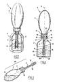
- the device 1 for packaging and application represented in the Figures 1 and 2 comprises a first container 2, a second container 3 superimposed on the first along a longitudinal axis X and an applicator 4 having an inner channel 5 through which the two containers 2 and 3 can communicate.
- the device 1 comes from the assembly of the kit represented in FIG. figure 4 , wherein the first container 2, which contains a first substance A, is closed by an individual cap 8.
- the second container 3, which contains a second substance B, is also closed by an individual cap 7.
- the applicator 4 can be initially separated from containers 2 and 3, as seen on figure 4 .
- the individual plugs 7 and 8 each comprise an internally threaded mounting skirt 9 and a sealing lip 10. This is arranged to seal on the radially inner surface of the neck 11 of the container 2 with respect to the plug 8 and the neck 12 of the container 3 with respect to the plug 7.
- the substance A is for example a coloring oxidant and the substance B a dye intended to be mixed with the substance A at the time of use.
- the second container 3 comprises a flexible wall, elastically deformable, on which the user can press to reduce its internal volume.
- the applicator 4 comprises an elongated portion 14 of axis X, provided with an enlarged portion 20 which is connected to a coupling portion 13, which makes it possible to secure the receptacles 2 and 3.
- the elongate portion 14 has a lower portion 15.
- the latter has for example, as illustrated, reliefs 16 made monolithically with the elongate portion 14.
- the reliefs 16 are constituted for example by a succession of teeth.
- the coupling portion 13 comprises a first tubular skirt 18 of axis X, threaded internally, arranged to screw on the neck 11 of the first container 2 and a second tubular skirt 19 of axis X also, arranged to screw on the neck 12 of the second container 3.
- the skirts 18 and 19 may, where appropriate, have different inside diameters, in order to avoid the risk of inverting containers 2 and 3 during the assembly of the device 1.
- the coupling part 13 also comprises sealing for sealing its fastening on the container 3.
- sealing means consist, in the example considered, by an annular sealing lip 22 arranged to be applied on the inner surface of the neck 12.
- the outer surface 21 of the widened portion is sealingly applied to the lower surface of the neck 11.
- the channel 5 opens at the lower end of the elongated portion 14 through an orifice 25, which may be located for example at a distance relatively close to the bottom 26 of the first container 2, as seen on the figure 2 .
- the section of the channel 5 is small enough to avoid a significant leakage of the substance A during this operation, better avoid any flow.
- the user can then press several times the flexible wall of the container 3 to expel the substance A contained inside the first container 2 and stir the resulting mixture. Whenever the user stops exerting pressure on the wall of the second container 3, it resumes elastically its initial shape.
- the presence of the reliefs 16 may contribute to the homogenization of the mixture M under the effect of the turbulence created in the first container 2 by the variation of the internal volume of the second container 3.
- the non-completely airtight fastening of the skirt 18 on the neck 11 and the clearance between the enlarged portion 20 and the neck 11 can facilitate the departure of the air contained in the container 2 during its filling by the substance contained in the container 3.
- the mixture M can be dispensed by again separating the assembly 30 from the first container 2, as illustrated in FIG. figure 3 .
- the container 3 then serves as a gripping member.
- the mixture M can be applied to the hair by pressing the wall of the second container 3 and the reliefs 16 can be used to distribute the product on the hair, the hair being engageable between them.
- the kit may comprise a plug 33 arranged to attach to the skirt 19 of the applicator 4, the latter being proposed to the user already in place on the first container 2.
- the plug 33 may comprise a central shutter 34 arranged for close the channel 5 of the applicator.
- the user can for example remove the plugs 7 and 33 and then screw the skirt 19 on the neck 12 of the second container 3.
- the kit may also include, as illustrated in figure 7 , a shutter 36 fixed to the end of the elongated portion 14 of the applicator 4 to close the channel 5.
- the applicator 4 can be proposed to the user already in place on the first container 2.
- the user can remove the cap 7 and screw the skirt 19 on the neck 12 of the second container 3.
- the shutter 36 is still in place at the end of the applicator 4, which prevents any risk of flow of the substance A out of the first container 2.
- the user can exert pressure on the wall of the second container 3 to cause the expulsion of the shutter 36 and allow the substances A and B to mix.
- the kit comprises the container 2 containing the substance A, closed by the cap 8, and the container 3 containing the substance B, closed by the applicator 4, the latter being provided at its free end with a sealing means 40 that was also represented at the figure 9 .
- This sealing means 40 comprises, for example, as illustrated, a cap comprising a pin 21 connected by a preferential annular zone of rupture 42 to a flange 43 projecting radially inwards at one end of the channel 5.
- the cap is advantageously made monolithically with the elongated portion 14 of the applicator 4, by plastic molding.
- the closure means 40 are arranged to automatically switch from a closure configuration to an open configuration allowing the substance B to mix with the substance A, when the elongated portion 14 of the applicator 4 is introduced into the container 2.
- This configuration change can be obtained for example by cooperation between the closure means 40 and the bottom of the container 2 in which the applicator 4 is introduced.
- the pin 41 thus bears against the bottom of the container 2 before the end of the screwing of the skirt 18 on the neck 11 of the container 2 and the annular zone 42 breakable breaks, which has the consequence that at the end of the screwing of the applicator, the pin 41 is raised in the channel 5.
- the diameter of the annular zone 42 is preferably clearly less than the inside diameter of the channel 5.
- shutter means 40 could be made otherwise.
- the closure means 40 comprise a shutter attached to the elongated portion 14 of the applicator 4 and held thereon, for example by snapping, friction, gluing or welding.
- the shutter is for example a heat-sealed cover at the end of the elongated portion 14 that the user can remove or drill before the introduction of the applicator 4 in the container 2. If necessary, the bottom of the latter could be provided with a pin that would perforate the aforementioned operculum.
- the channel 5 opens through lateral orifices 38 between the reliefs 16.
- These may for example be constituted by a succession of teeth or bristles, each of these reliefs extending on the outer periphery of the elongate portion.
- outer periphery is meant a region of the elongate portion extending about the X axis.
- the reliefs 16, particularly the teeth or bristles, may each extend in a direction substantially perpendicular to the longitudinal axis X.
- All orifices 38 may open, if necessary, on the same side of the applicator.
- the reliefs 16 may possibly not be made in one piece with the elongated portion 14 by molding of material.
Landscapes
- Engineering & Computer Science (AREA)
- Mechanical Engineering (AREA)
- Closures For Containers (AREA)
- Containers And Packaging Bodies Having A Special Means To Remove Contents (AREA)
- Package Specialized In Special Use (AREA)
- Coating Apparatus (AREA)
Abstract
Description
La présente invention concerne les dispositifs de conditionnement et d'application d'un produit liquide, par exemple un produit de coloration de la chevelure résultant du mélange d'une première et d'une seconde substance conditionnées séparément.The present invention relates to devices for packaging and applying a liquid product, for example a product for coloring the hair resulting from the mixing of a first and a second substance packaged separately.
La demande de
Le
On connaît par ailleurs par les brevets
Le brevet PAVENIK
La demande internationale DORR
Il existe un besoin pour bénéficier d'un dispositif de conditionnement et d'application permettant le conditionnement séparé de deux produits et leur mélange extemporané et l'application du mélange obtenu au moyen d'un applicateur, par exemple un applicateur configuré pour appliquer le mélange sur la chevelure.There is a need to benefit from a packaging and application device allowing the separate packaging of two products and their extemporaneous mixing and the application of the mixture obtained by means of an applicator, for example an applicator configured to apply the mixture. on the hair.
Selon un premier de ses aspects, l'invention a ainsi pour objet un kit de conditionnement et d'application comportant :
- un premier récipient contenant une première substance,
- un deuxième récipient contenant une deuxième substance, différente de la première substance,
- un applicateur avec lequel les deux récipients peuvent être solidarisés, cet applicateur comportant au moins une partie allongée pouvant s'engager dans l'un des récipients et traversée par un canal par lequel la substance contenue dans l'un des récipients peut circuler pour se mélanger avec la substance contenue dans l'autre récipient, la première substance étant un liquide ou une poudre et la deuxième substance étant un liquide.
- a first container containing a first substance,
- a second container containing a second substance, different from the first substance,
- an applicator with which the two containers can be secured, this applicator comprising at least one elongated part engageable in one of the containers and through which a channel through which the substance contained in one of the containers can circulate to mix with the substance contained in the other container, the first substance being a liquid or a powder and the second substance being a liquid.
L'invention permet d'utiliser, pour appliquer le mélange, l'ensemble formé par l'un des récipients et l'applicateur, cet ensemble présentant un poids réduit par rapport au poids total du kit. En outre, le kit est de fabrication et d'utilisation relativement simples.The invention makes it possible to use, for applying the mixture, the assembly formed by one of the containers and the applicator, this assembly having a reduced weight relative to the total weight of the kit. In addition, the kit is relatively simple to manufacture and use.
La première substance peut être notamment un colorant capillaire.The first substance may be in particular a hair dye.
La deuxième substance peut être un oxydant de coloration capillaire.The second substance can be a hair coloring oxidant.
Le récipient destiné à être lié à l'applicateur lors de l'application est de préférence réalisé avec une paroi flexible, élastiquement déformable, ce qui permet à l'utilisateur de créer à l'intérieur de celui-ci une surpression pour expulser hors du récipient le produit contenu à l'intérieur ou pour prélever du mélange entre deux utilisations.The container intended to be connected to the applicator during the application is preferably made with a flexible, elastically deformable wall, which allows the user to create inside it an overpressure to expel out of the container the product contained inside or to collect the mixture between two uses.
Les deux récipients peuvent, le cas échéant, comporter chacun une paroi flexible, élastiquement déformable.The two containers may, where appropriate, each comprise a flexible wall, elastically deformable.
L'applicateur peut être réalisé avec différentes formes, selon l'application visée. Notamment dans le cas où les première et deuxième substances sont destinées au traitement de la chevelure, l'applicateur peut comporter une partie d'application réalisée avec au moins un relief, par exemple une succession de dents ou de poils.The applicator can be made with different shapes, depending on the intended application. In particular, in the case where the first and second substances are intended for the treatment of the hair, the applicator may comprise an application part made with at least one relief, for example a succession of teeth or bristles.
Le canal précité de l'applicateur peut déboucher à une extrémité de la partie allongée.The aforementioned channel of the applicator can lead to one end of the elongated portion.
En variante ou additionnellement, ce canal peut déboucher par au moins un orifice latéral de la partie d'application, cet orifice latéral étant par exemple situé entre deux dents ou poils lorsque la partie d'application comporte au moins une succession de dents ou poils permettant de peigner les cheveux.Alternatively or additionally, this channel can lead to at least one lateral orifice of the application part, this lateral orifice being for example located between two teeth or bristles when the application part comprises at least one succession of teeth or bristles allowing to comb the hair.
L'applicateur peut comporter au moins un organe d'étanchéité configuré pour s'appliquer de manière étanche sur l'un au moins des récipients.The applicator may comprise at least one sealing member configured to apply sealingly to at least one of the containers.
L'un au moins des récipients peut comporter un col et l'applicateur peut comporter au moins une lèvre d'étanchéité agencée pour s'appliquer sur la surface radialement intérieure de ce col.At least one of the containers may comprise a neck and the applicator may comprise at least one sealing lip arranged to be applied on the radially inner surface of this neck.
Il peut s'avérer souhaitable que l'air puisse s'échapper du récipient à l'intérieur duquel s'étend la partie allongée afin de faciliter l'écoulement de la substance contenue dans l'autre récipient. L'applicateur peut ainsi se fixer de manière non étanche sur le récipient dans lequel la partie allongée s'étend.It may be desirable for air to escape from the container within which the elongate portion extends to facilitate flow of the substance contained in the other container. The applicator can thus be fixed in an unsealed manner on the container in which the elongate portion extends.
En variante, l'applicateur peut comporter, le cas échéant, une surface d'étanchéité constituée par exemple par une portion de la partie allongée de l'applicateur, cette portion étant agencée pour s'appliquer sur une surface intérieure du récipient à l'intérieur duquel la partie allongée s'étend.As a variant, the applicator may comprise, where appropriate, a sealing surface formed for example by a portion of the elongated portion of the applicator, this portion being arranged to be applied on an inner surface of the container to the inside which the elongated part extends.
L'applicateur peut comporter une première jupe tubulaire, filetée intérieurement, agencée pour recevoir le premier récipient et une deuxième jupe tubulaire, filetée intérieurement, agencée pour recevoir le deuxième récipient.The applicator may comprise a first tubular skirt, threaded internally, arranged to receive the first container and a second tubular skirt, threaded internally, arranged to receive the second container.
Le canal de l'applicateur, par lequel la substance contenue dans l'un des récipients peut atteindre l'autre récipient, peut être réalisé avec une section intérieure suffisamment faible pour éviter une fuite de cette substance lorsque l'ensemble constitué par l'applicateur et l'un des récipients n'est pas encore monté sur l'autre récipient.The applicator channel, through which the substance contained in one of the containers can reach the other container, can be made with an inner section sufficiently small to prevent leakage of this substance when the assembly constituted by the applicator and one of the containers is not yet mounted on the other container.
L'applicateur peut comporter un opercule sécable avant la première utilisation, fermant le canal précité à une extrémité.
- Des bouchons peuvent être agencés pour fermer de manière étanche les premier et second récipients en l'absence de l'applicateur.
- L'applicateur agencé pour se fixer sur les deux récipients afin d'établir une communication entre les récipients, peut comporter au moins une succession de reliefs sur son pourtour extérieur, par exemple réalisés par moulage de matière de façon monolithique avec l'applicateur, notamment au moins une succession de dents ou poils réalisés par moulage de matière de façon monolithique avec l'applicateur.
- Caps may be arranged to seal the first and second containers in the absence of the applicator.
- The applicator arranged to be fixed on the two receptacles in order to establish a communication between the receptacles may comprise at least one succession of reliefs on its outer periphery, for example made by molding material monolithically with the applicator, in particular at least one succession of teeth or bristles made by molding material monolithically with the applicator.
Le canal de l'applicatur peut être fermé à une extrémité par des moyens d'obturation agencés pour passer d'une configuration d'obturation à une configuration ouverte permettant aux deux récipients de communiquer entre eux, en réponse à une action exercée par l'utilisateur.The applicator channel may be closed at one end by closure means arranged to move from a closure configuration to an open configuration allowing the two containers to communicate with each other in response to an action exerted by the user.
Les moyens d'obturation peuvent être configurés de manière à changer de configuration en venant en appui contre le fond du premier récipient lorsque l'applicateur est engagé dans celui-ci. Les moyens d'obturation peuvent comporter un picot relié à la partie allongée de l'applicateur par une zone frangible. Les moyens d'obturation peuvent être réalisés de façon monolithique par moulage de matière plastique avec l'applicateur.The closure means may be configured to change configuration by bearing against the bottom of the first container when the applicator is engaged therein. The closure means may comprise a pin connected to the elongate portion of the applicator by a frangible zone. The sealing means can be made monolithically by molding plastic material with the applicator.
L'invention pourra être mieux comprise à la lecture de la description détaillée qui va suivre, d'exemples de mise en oeuvre non limitatifs de celle-ci, et à l'examen du dessin annexé, sur lequel :
- la
figure 1 représente en perspective, de manière schématique, avec arrachement partiel, un exemple de dispositif de conditionnement et d'application réalisé conformément à l'invention, - la
figure 2 est une coupe longitudinale schématique du dispositif de lafigure 1 , - la
figure 3 représente en coupe longitudinale l'ensemble constitué par l'applicateur et le récipient servant d'organe de préhension, - la
figure 4 représente de manière schématique un exemple de kit de conditionnement et d'application réalisé conformément à l'invention, - la
figure 5 illustre l'utilisation du kit de lafigure 4 , - les
figures 6 à 8 représentent trois exemples de kits conformes à l'invention, - la
figure 9 représente à échelle agrandie le détail IX de lafigure 8 , et - la
figure 10 est une coupe longitudinale partielle et schématique d'une variante de réalisation de l'applicateur.
- the
figure 1 represents in perspective, schematically, partially broken away, an exemplary packaging and application device produced according to the invention, - the
figure 2 is a schematic longitudinal section of the device of thefigure 1 , - the
figure 3 represents in longitudinal section the assembly constituted by the applicator and the container serving as a gripping member, - the
figure 4 schematically represents an example of a packaging and application kit made according to the invention, - the
figure 5 illustrates the use of the kit of thefigure 4 , - the
Figures 6 to 8 represent three examples of kits according to the invention, - the
figure 9 represents on an enlarged scale detail IX of thefigure 8 , and - the
figure 10 is a partial and schematic longitudinal section of an alternative embodiment of the applicator.
Le dispositif 1 de conditionnement et d'application représenté aux
Le dispositif 1 est issu de l'assemblage du kit représenté à la
Les bouchons individuels 7 et 8 comportent chacun une jupe de montage 9 filetée intérieurement et une lèvre d'étanchéité 10. Celle-ci est agencée pour s'appliquer de manière étanche sur la surface radialement intérieure du col 11 du récipient 2 en ce qui concerne le bouchon 8 et du col 12 du récipient 3 en ce qui concerne le bouchon 7.The individual plugs 7 and 8 each comprise an internally threaded mounting
La substance A est par exemple un oxydant de coloration et la substance B un colorant destiné à être mélangé à la substance A au moment de l'utilisation.The substance A is for example a coloring oxidant and the substance B a dye intended to be mixed with the substance A at the time of use.
Le deuxième récipient 3 comporte une paroi flexible, élastiquement déformable, sur laquelle l'utilisateur peut appuyer pour diminuer son volume intérieur.The
L'applicateur 4 comporte une partie allongée 14 d'axe X, munie supérieurement d'une portion élargie 20 se raccordant à une partie de couplage 13, laquelle permet de solidariser les récipients 2 et 3. La partie allongée 14 comporte inférieurement une partie d'application 15. Cette dernière présente par exemple, comme illustré, des reliefs 16 réalisés de façon monolithique avec la partie allongée 14. Les reliefs 16 sont constitués par exemple par une succession de dents.The
La partie de couplage 13 comporte une première jupe tubulaire 18 d'axe X, filetée intérieurement, agencée pour se visser sur le col 11 du premier récipient 2 et une deuxième jupe tubulaire 19 d'axe X également, agencée pour se visser sur le col 12 du deuxième récipient 3.The
Les jupes 18 et 19 peuvent, le cas échéant, présenter des diamètres intérieurs différents, afin d'éviter le risque d'inverser des récipients 2 et 3 lors de l'assemblage du dispositif 1. La partie de couplage 13 comporte également des moyens d'étanchéité permettant d'assurer l'étanchéité de sa fixation sur le récipient 3.The
Ces moyens d'étanchéité sont constitués, dans l'exemple considéré, par une lèvre annulaire d'étanchéité 22 agencée pour s'appliquer sur la surface intérieure du col 12.These sealing means consist, in the example considered, by an
Dans une variante non illustrée, la surface extérieure 21 de la partie élargie s'applique de manière étanche sur la surface inférieure du col 11.In a non-illustrated variant, the
Dans l'exemple considéré, le canal 5 débouche à l'extrémité inférieure de la partie allongée 14 par un orifice 25, lequel peut être situé par exemple à une distance relativement proche du fond 26 du premier récipient 2, comme on le voit sur la
Pour mélanger les substances A et B, l'utilisateur peut procéder comme suit.To mix substances A and B, the user can proceed as follows.
Il ôte les bouchons 7 et 8 puis visse l'applicateur 4 sur le deuxième récipient 3 et enfin introduit l'ensemble 30 formé par l'applicateur 4 et le deuxième récipient 3 dans le premier récipient 2, comme illustré à la
La section du canal 5 est suffisamment faible pour éviter une fuite importante de la substance A durant cette opération, mieux éviter tout écoulement.The section of the
L'utilisateur peut ensuite presser plusieurs fois la paroi flexible du récipient 3 pour chasser la substance A contenue à l'intérieur dans le premier récipient 2 et brasser le mélange obtenu. Chaque fois que l'utilisateur cesse d'exercer une pression sur la paroi du deuxième récipient 3, celle-ci reprend par élasticité sa forme initiale. La présence des reliefs 16 peut contribuer à l'homogénéisation du mélange M sous l'effet des turbulences créées dans le premier récipient 2 par la variation du volume intérieur du deuxième récipient 3. La fixation non totalement étanche à l'air de la jupe 18 sur le col 11 et le jeu existant entre la partie élargie 20 et le col 11 peut faciliter le départ de l'air contenu dans le récipient 2 lors de son remplissage par la substance contenue dans le récipient 3.The user can then press several times the flexible wall of the
Le mélange M peut être distribué en séparant à nouveau l'ensemble 30 du premier récipient 2, comme illustré à la
Bien entendu, l'invention n'est pas limitée à l'exemple de réalisation qui vient d'être décrit et diverses modifications peuvent être apportées aux récipients ainsi qu'à l'applicateur.Of course, the invention is not limited to the embodiment which has just been described and various modifications can be made to the containers and the applicator.
Par exemple, comme illustré à la
Le kit peut encore comporter, comme illustré à la
Dans l'exemple des
Ce moyen d'obturation 40 comporte par exemple, comme illustré, un opercule comportant un picot 21 relié par une zone annulaire de rupture préférentielle 42 à une collerette 43 faisant saillie radialement vers l'intérieur à une extrémité du canal 5. L'opercule est avantageusement réalisé de manière monolithique avec la partie allongée 14 de l'applicateur 4, par moulage de matière plastique.This sealing means 40 comprises, for example, as illustrated, a cap comprising a
Avantageusement, comme c'est le cas dans l'exemple représenté sur les
Dans l'exemple des
Bien entendu, les moyens d'obturation 40 pourraient être réalisés autrement encore.Of course, the shutter means 40 could be made otherwise.
Dans des variantes non illustrées, les moyens d'obturation 40 comportent un obturateur rapporté sur la partie allongée 14 de l'applicateur 4 et maintenu sur celle-ci par exemple par encliquetage, friction, collage ou soudage. L'obturateur est par exemple un opercule thermosoudé à l'extrémité de la partie allongée 14 que l'utilisateur peut enlever ou percer avant la mise en place de l'applicateur 4 dans le récipient 2. Le cas échéant, le fond de ce dernier pourrait être pourvu d'un picot qui viendrait perforer l'opercule précité.In non-illustrated variants, the closure means 40 comprise a shutter attached to the
La partie de l'applicateur servant à l'application peut être réalisée de différentes façons et dans la variante illustrée à la
Tous les orifices 38 peuvent déboucher, le cas échéant, d'un même côté de l'applicateur. Les reliefs 16 peuvent éventuellement ne pas être réalisés d'un seul tenant avec la partie allongée 14 par moulage de matière.All
Dans toute la description, y compris les revendications, l'expression « comportant un » doit être comprise comme étant synonyme de « comportant au moins un », sauf si le contraire est spécifié.Throughout the description, including the claims, the phrase "having one" should be understood as being synonymous with "having at least one", unless the opposite is specified.
Claims (18)
- A packaging and applicator kit comprising:- a first receptacle containing a first substance;- a second receptacle containing a second substance that is different from the first substance;- an applicator to which both receptacles can be secured, said applicator comprising at least an elongate portion, said portion being capable of engaging in one of the receptacles and having a through channel through which the substance contained in one of the receptacles can flow for mixing with the substance contained in the other receptacle, wherein the first substance is a liquid or a powder and wherein the second substance is a liquid.
- A kit according to claim 1, comprising:stoppers arranged to close the first receptacle and the second receptacle in leaktight manner, in the absence of the applicator.
- A kit according to claim 1 or 2, the applicator comprising at least a succession of projections on its outer periphery, in particular at least one succession of teeth or bristles, that are molded integrally with the applicator.
- A kit according to any preceding claim, the channel being closed at one end by closure means arranged to move away from a closed configuration to an open configuration, thereby enabling the receptacles to communicate with each other, in response to an action exerted by the user.
- A kit according to claim 1, wherein the first substance is a liquid, in particular a hair dye.
- A kit according to claim 1, wherein the second substance is a hair coloring oxidant.
- A kit according to any one of claims 1 to 6, wherein at least one of both receptacles is made in a flexible and elastically-deformable wall.
- A kit according to claim 7, wherein at least the receptacle, which is secured to the applicator during application of the mixture, has a flexible and elastically-deformable wall.
- A kit according to any one of claims 1 to 8, wherein both receptacles each have a flexible and elastically-deformable wall.
- A kit according to claim 1, wherein the applicator has an applicator portion made with at least one projection, in particular a succession of teeth or of bristles.
- A kit according to claim 1, wherein the channel opens out at one end of the elongate portion.
- A kit according to claim 1, wherein the channel opens out on the outside through at least one side hole, said at least one outside hole being in particular situated between two teeth or two bristles.
- A kit according to any one of claims 1 to 12, wherein the applicator includes at least one sealing member configured to be pressed in leaktight manner against one of the receptacles.
- A kit according to claim 13, wherein the applicator is arranged to be fastened to the receptacle in which the elongate portion extends, in a manner that is not completely airtight.
- A kit according to any one of claims 1 to 14, wherein the applicator includes both a first tubular skirt that has an inside thread and that is arranged to receive the first receptacle, and a second tubular skirt that has an inside thread and that is arranged to receive the second receptacle.
- A kit according to claim 4, wherein the closure means are configured to change the configuration by bearing against the bottom of the first receptacle when the applicator is engaged therein.
- A kit according to claim 16, wherein the closure means comprises a spike connected to the elongate portion by a breakable zone.
- A kit according to claim 16 or claim 17, wherein the closure means are made integrally with the applicator by molding a material.
Applications Claiming Priority (2)
| Application Number | Priority Date | Filing Date | Title |
|---|---|---|---|
| FR0450104A FR2865196B1 (en) | 2004-01-20 | 2004-01-20 | KIT COMPRISING TWO CONTAINERS AND AN APPLICATOR |
| FR0450104 | 2004-01-20 |
Publications (2)
| Publication Number | Publication Date |
|---|---|
| EP1557371A1 EP1557371A1 (en) | 2005-07-27 |
| EP1557371B1 true EP1557371B1 (en) | 2010-08-18 |
Family
ID=34630688
Family Applications (1)
| Application Number | Title | Priority Date | Filing Date |
|---|---|---|---|
| EP05300029A Not-in-force EP1557371B1 (en) | 2004-01-20 | 2005-01-12 | Kit comprising two containers and an applicator |
Country Status (5)
| Country | Link |
|---|---|
| EP (1) | EP1557371B1 (en) |
| AT (1) | ATE478016T1 (en) |
| DE (1) | DE602005022955D1 (en) |
| ES (1) | ES2350046T3 (en) |
| FR (1) | FR2865196B1 (en) |
Families Citing this family (1)
| Publication number | Priority date | Publication date | Assignee | Title |
|---|---|---|---|---|
| FR2927783A1 (en) | 2008-02-26 | 2009-08-28 | Oreal | DEVICE FOR CONDITIONING AND DISPENSING A COSMETIC PRODUCT |
Family Cites Families (11)
| Publication number | Priority date | Publication date | Assignee | Title |
|---|---|---|---|---|
| FR1043061A (en) * | 1951-08-27 | 1953-11-05 | Pharma Debarge Lab | Device for packaging a powder product to be mixed externally with a liquid |
| US2926374A (en) | 1957-01-23 | 1960-03-01 | Adler Leon | Liquid-brushing device |
| US3178755A (en) | 1963-12-13 | 1965-04-20 | Edward L Kormann | Liquid dispenser and applicator |
| FR2552404B1 (en) | 1983-09-26 | 1987-12-24 | Merck Sharp & Dohme | ASSEMBLY FOR PREPARING AND DELIVERING A SOLUTION, SHUTTERING PLUG FOR SUCH ASSEMBLY AND METHOD FOR MANUFACTURING THE SAME |
| US4690579A (en) | 1985-09-03 | 1987-09-01 | Tuckman Drew E | Brush extension device |
| JPH02179118A (en) | 1988-12-29 | 1990-07-12 | Fujitsu Ltd | Semiconductor integrated circuit |
| US5345981A (en) | 1992-09-24 | 1994-09-13 | Stanford Pavenick | Applicator for fluid products |
| US5307847A (en) * | 1992-09-24 | 1994-05-03 | Stanford Pavenick | Applicator for fluid products |
| US5540654A (en) | 1994-09-02 | 1996-07-30 | North Carolina State University | Iontophoretic electrode |
| JP2002179118A (en) | 2000-12-08 | 2002-06-26 | Yoshida Industry Co Ltd | Two-part liquid mixing and pouring container with hair comb |
| FR2834190B1 (en) * | 2001-12-28 | 2004-09-24 | Philippe Marie Jacques Dorr | DEVICE FOR THE TREATMENT OF SURFACES BY THE COMBINED ACTION OF MECHANICAL FRICTIONS AND LIQUIDS |
-
2004
- 2004-01-20 FR FR0450104A patent/FR2865196B1/en not_active Expired - Fee Related
-
2005
- 2005-01-12 DE DE602005022955T patent/DE602005022955D1/en active Active
- 2005-01-12 AT AT05300029T patent/ATE478016T1/en not_active IP Right Cessation
- 2005-01-12 ES ES05300029T patent/ES2350046T3/en active Active
- 2005-01-12 EP EP05300029A patent/EP1557371B1/en not_active Not-in-force
Also Published As
| Publication number | Publication date |
|---|---|
| DE602005022955D1 (en) | 2010-09-30 |
| EP1557371A1 (en) | 2005-07-27 |
| FR2865196B1 (en) | 2008-05-30 |
| ES2350046T3 (en) | 2011-01-17 |
| FR2865196A1 (en) | 2005-07-22 |
| ATE478016T1 (en) | 2010-09-15 |
Similar Documents
| Publication | Publication Date | Title |
|---|---|---|
| EP1136386B1 (en) | Device for the extemporaneous mixture of at least two products | |
| CA2141967C (en) | Multiple compartment dispenser for storing and blending contents | |
| EP1557111B1 (en) | Applicator with an applying element mounted on a recipient containing a product to be applied | |
| EP0260179B1 (en) | Assembly for the separate storage of two products and simultaneous distribution after mixing | |
| EP2990350A1 (en) | Dispensing device | |
| FR2810639A1 (en) | SET FOR THE EXTEMPORANEOUS MIXTURE OF TWO PRODUCTS | |
| EP0572645A1 (en) | Assembly for mixing two different separately-stored products. | |
| EP0238371B1 (en) | Container for a viscous liquid to which an additive is added when first used | |
| EP0790190B1 (en) | One-piece container for preserving in a separated condition and mixing at least two products | |
| CA2299595C (en) | Packaging for mixing a product with several components | |
| EP0430724A1 (en) | Device for applying a liquid or pasty product to a surface | |
| FR2747106A1 (en) | DEVICE FOR PACKAGING AND APPLYING A CAPILLARY PRODUCT | |
| WO2006090061A1 (en) | Creamy product dispensing tube | |
| CH629149A5 (en) | SHUTTERING AND DISPENSING DEVICE FOR A CONTAINER PROVIDED WITH A NECK. | |
| EP1221419B1 (en) | Assembly for extemporaneous mixture of two products | |
| EP1557371B1 (en) | Kit comprising two containers and an applicator | |
| EP0905049A1 (en) | Container for a three-component product | |
| JP5590554B2 (en) | Application container | |
| WO2009056736A1 (en) | Fluid dispensing device | |
| FR2811639A1 (en) | DEVICE FOR PACKAGING AND DISPENSING A PRODUCT, ESPECIALLY A HAIR PRODUCT | |
| EP1475315A1 (en) | Assembly for storage and application of a liquid product | |
| FR3042959A1 (en) | PACKAGING DEVICE FOR A PRODUCT TO BE DISTRIBUTED, IN PARTICULAR FOR A FRAGRANCE | |
| EP1621102B1 (en) | Storage and application unit | |
| WO1999029584A1 (en) | Outlet device for fluid container | |
| EP1502872B1 (en) | Device with a double dispensing system |
Legal Events
| Date | Code | Title | Description |
|---|---|---|---|
| PUAI | Public reference made under article 153(3) epc to a published international application that has entered the european phase |
Free format text: ORIGINAL CODE: 0009012 |
|
| 17P | Request for examination filed |
Effective date: 20050112 |
|
| AK | Designated contracting states |
Kind code of ref document: A1 Designated state(s): AT BE BG CH CY CZ DE DK EE ES FI FR GB GR HU IE IS IT LI LT LU MC NL PL PT RO SE SI SK TR |
|
| AX | Request for extension of the european patent |
Extension state: AL BA HR LV MK YU |
|
| AKX | Designation fees paid |
Designated state(s): AT BE BG CH CY CZ DE DK EE ES FI FR GB GR HU IE IS IT LI LT LU MC NL PL PT RO SE SI SK TR |
|
| 17Q | First examination report despatched |
Effective date: 20070711 |
|
| GRAP | Despatch of communication of intention to grant a patent |
Free format text: ORIGINAL CODE: EPIDOSNIGR1 |
|
| GRAS | Grant fee paid |
Free format text: ORIGINAL CODE: EPIDOSNIGR3 |
|
| GRAA | (expected) grant |
Free format text: ORIGINAL CODE: 0009210 |
|
| AK | Designated contracting states |
Kind code of ref document: B1 Designated state(s): AT BE BG CH CY CZ DE DK EE ES FI FR GB GR HU IE IS IT LI LT LU MC NL PL PT RO SE SI SK TR |
|
| REG | Reference to a national code |
Ref country code: GB Ref legal event code: FG4D Free format text: NOT ENGLISH |
|
| REG | Reference to a national code |
Ref country code: CH Ref legal event code: EP |
|
| REG | Reference to a national code |
Ref country code: IE Ref legal event code: FG4D Free format text: LANGUAGE OF EP DOCUMENT: FRENCH |
|
| REF | Corresponds to: |
Ref document number: 602005022955 Country of ref document: DE Date of ref document: 20100930 Kind code of ref document: P |
|
| REG | Reference to a national code |
Ref country code: NL Ref legal event code: VDEP Effective date: 20100818 |
|
| REG | Reference to a national code |
Ref country code: ES Ref legal event code: FG2A Effective date: 20110104 |
|
| LTIE | Lt: invalidation of european patent or patent extension |
Effective date: 20100818 |
|
| PG25 | Lapsed in a contracting state [announced via postgrant information from national office to epo] |
Ref country code: AT Free format text: LAPSE BECAUSE OF FAILURE TO SUBMIT A TRANSLATION OF THE DESCRIPTION OR TO PAY THE FEE WITHIN THE PRESCRIBED TIME-LIMIT Effective date: 20100818 Ref country code: FI Free format text: LAPSE BECAUSE OF FAILURE TO SUBMIT A TRANSLATION OF THE DESCRIPTION OR TO PAY THE FEE WITHIN THE PRESCRIBED TIME-LIMIT Effective date: 20100818 Ref country code: LT Free format text: LAPSE BECAUSE OF FAILURE TO SUBMIT A TRANSLATION OF THE DESCRIPTION OR TO PAY THE FEE WITHIN THE PRESCRIBED TIME-LIMIT Effective date: 20100818 |
|
| PG25 | Lapsed in a contracting state [announced via postgrant information from national office to epo] |
Ref country code: SI Free format text: LAPSE BECAUSE OF FAILURE TO SUBMIT A TRANSLATION OF THE DESCRIPTION OR TO PAY THE FEE WITHIN THE PRESCRIBED TIME-LIMIT Effective date: 20100818 Ref country code: PT Free format text: LAPSE BECAUSE OF FAILURE TO SUBMIT A TRANSLATION OF THE DESCRIPTION OR TO PAY THE FEE WITHIN THE PRESCRIBED TIME-LIMIT Effective date: 20101220 Ref country code: PL Free format text: LAPSE BECAUSE OF FAILURE TO SUBMIT A TRANSLATION OF THE DESCRIPTION OR TO PAY THE FEE WITHIN THE PRESCRIBED TIME-LIMIT Effective date: 20100818 Ref country code: BG Free format text: LAPSE BECAUSE OF FAILURE TO SUBMIT A TRANSLATION OF THE DESCRIPTION OR TO PAY THE FEE WITHIN THE PRESCRIBED TIME-LIMIT Effective date: 20101118 Ref country code: CY Free format text: LAPSE BECAUSE OF FAILURE TO SUBMIT A TRANSLATION OF THE DESCRIPTION OR TO PAY THE FEE WITHIN THE PRESCRIBED TIME-LIMIT Effective date: 20100818 Ref country code: IS Free format text: LAPSE BECAUSE OF FAILURE TO SUBMIT A TRANSLATION OF THE DESCRIPTION OR TO PAY THE FEE WITHIN THE PRESCRIBED TIME-LIMIT Effective date: 20101218 |
|
| REG | Reference to a national code |
Ref country code: IE Ref legal event code: FD4D |
|
| PG25 | Lapsed in a contracting state [announced via postgrant information from national office to epo] |
Ref country code: NL Free format text: LAPSE BECAUSE OF FAILURE TO SUBMIT A TRANSLATION OF THE DESCRIPTION OR TO PAY THE FEE WITHIN THE PRESCRIBED TIME-LIMIT Effective date: 20100818 Ref country code: GR Free format text: LAPSE BECAUSE OF FAILURE TO SUBMIT A TRANSLATION OF THE DESCRIPTION OR TO PAY THE FEE WITHIN THE PRESCRIBED TIME-LIMIT Effective date: 20101119 Ref country code: SE Free format text: LAPSE BECAUSE OF FAILURE TO SUBMIT A TRANSLATION OF THE DESCRIPTION OR TO PAY THE FEE WITHIN THE PRESCRIBED TIME-LIMIT Effective date: 20100818 |
|
| PG25 | Lapsed in a contracting state [announced via postgrant information from national office to epo] |
Ref country code: DK Free format text: LAPSE BECAUSE OF FAILURE TO SUBMIT A TRANSLATION OF THE DESCRIPTION OR TO PAY THE FEE WITHIN THE PRESCRIBED TIME-LIMIT Effective date: 20100818 Ref country code: IE Free format text: LAPSE BECAUSE OF FAILURE TO SUBMIT A TRANSLATION OF THE DESCRIPTION OR TO PAY THE FEE WITHIN THE PRESCRIBED TIME-LIMIT Effective date: 20100818 |
|
| PG25 | Lapsed in a contracting state [announced via postgrant information from national office to epo] |
Ref country code: RO Free format text: LAPSE BECAUSE OF FAILURE TO SUBMIT A TRANSLATION OF THE DESCRIPTION OR TO PAY THE FEE WITHIN THE PRESCRIBED TIME-LIMIT Effective date: 20100818 Ref country code: EE Free format text: LAPSE BECAUSE OF FAILURE TO SUBMIT A TRANSLATION OF THE DESCRIPTION OR TO PAY THE FEE WITHIN THE PRESCRIBED TIME-LIMIT Effective date: 20100818 Ref country code: CZ Free format text: LAPSE BECAUSE OF FAILURE TO SUBMIT A TRANSLATION OF THE DESCRIPTION OR TO PAY THE FEE WITHIN THE PRESCRIBED TIME-LIMIT Effective date: 20100818 Ref country code: SK Free format text: LAPSE BECAUSE OF FAILURE TO SUBMIT A TRANSLATION OF THE DESCRIPTION OR TO PAY THE FEE WITHIN THE PRESCRIBED TIME-LIMIT Effective date: 20100818 |
|
| PLBE | No opposition filed within time limit |
Free format text: ORIGINAL CODE: 0009261 |
|
| STAA | Information on the status of an ep patent application or granted ep patent |
Free format text: STATUS: NO OPPOSITION FILED WITHIN TIME LIMIT |
|
| 26N | No opposition filed |
Effective date: 20110519 |
|
| BERE | Be: lapsed |
Owner name: L'OREAL Effective date: 20110131 |
|
| PG25 | Lapsed in a contracting state [announced via postgrant information from national office to epo] |
Ref country code: MC Free format text: LAPSE BECAUSE OF NON-PAYMENT OF DUE FEES Effective date: 20110131 |
|
| REG | Reference to a national code |
Ref country code: CH Ref legal event code: PL |
|
| REG | Reference to a national code |
Ref country code: DE Ref legal event code: R097 Ref document number: 602005022955 Country of ref document: DE Effective date: 20110519 |
|
| PG25 | Lapsed in a contracting state [announced via postgrant information from national office to epo] |
Ref country code: CH Free format text: LAPSE BECAUSE OF NON-PAYMENT OF DUE FEES Effective date: 20110131 Ref country code: LI Free format text: LAPSE BECAUSE OF NON-PAYMENT OF DUE FEES Effective date: 20110131 |
|
| PG25 | Lapsed in a contracting state [announced via postgrant information from national office to epo] |
Ref country code: BE Free format text: LAPSE BECAUSE OF NON-PAYMENT OF DUE FEES Effective date: 20110131 |
|
| PGFP | Annual fee paid to national office [announced via postgrant information from national office to epo] |
Ref country code: FR Payment date: 20120202 Year of fee payment: 8 |
|
| PGFP | Annual fee paid to national office [announced via postgrant information from national office to epo] |
Ref country code: DE Payment date: 20120104 Year of fee payment: 8 |
|
| PGFP | Annual fee paid to national office [announced via postgrant information from national office to epo] |
Ref country code: GB Payment date: 20120111 Year of fee payment: 8 Ref country code: IT Payment date: 20120118 Year of fee payment: 8 |
|
| PG25 | Lapsed in a contracting state [announced via postgrant information from national office to epo] |
Ref country code: LU Free format text: LAPSE BECAUSE OF NON-PAYMENT OF DUE FEES Effective date: 20110112 |
|
| PGFP | Annual fee paid to national office [announced via postgrant information from national office to epo] |
Ref country code: ES Payment date: 20120213 Year of fee payment: 8 |
|
| GBPC | Gb: european patent ceased through non-payment of renewal fee |
Effective date: 20130112 |
|
| PG25 | Lapsed in a contracting state [announced via postgrant information from national office to epo] |
Ref country code: TR Free format text: LAPSE BECAUSE OF FAILURE TO SUBMIT A TRANSLATION OF THE DESCRIPTION OR TO PAY THE FEE WITHIN THE PRESCRIBED TIME-LIMIT Effective date: 20100818 |
|
| REG | Reference to a national code |
Ref country code: FR Ref legal event code: ST Effective date: 20130930 |
|
| PG25 | Lapsed in a contracting state [announced via postgrant information from national office to epo] |
Ref country code: HU Free format text: LAPSE BECAUSE OF FAILURE TO SUBMIT A TRANSLATION OF THE DESCRIPTION OR TO PAY THE FEE WITHIN THE PRESCRIBED TIME-LIMIT Effective date: 20100818 Ref country code: DE Free format text: LAPSE BECAUSE OF NON-PAYMENT OF DUE FEES Effective date: 20130801 |
|
| REG | Reference to a national code |
Ref country code: DE Ref legal event code: R119 Ref document number: 602005022955 Country of ref document: DE Effective date: 20130801 |
|
| PG25 | Lapsed in a contracting state [announced via postgrant information from national office to epo] |
Ref country code: FR Free format text: LAPSE BECAUSE OF NON-PAYMENT OF DUE FEES Effective date: 20130131 Ref country code: GB Free format text: LAPSE BECAUSE OF NON-PAYMENT OF DUE FEES Effective date: 20130112 |
|
| PG25 | Lapsed in a contracting state [announced via postgrant information from national office to epo] |
Ref country code: IT Free format text: LAPSE BECAUSE OF NON-PAYMENT OF DUE FEES Effective date: 20130112 |
|
| REG | Reference to a national code |
Ref country code: ES Ref legal event code: FD2A Effective date: 20140321 |
|
| PG25 | Lapsed in a contracting state [announced via postgrant information from national office to epo] |
Ref country code: ES Free format text: LAPSE BECAUSE OF NON-PAYMENT OF DUE FEES Effective date: 20130113 |