EP1557224A1 - Ultrasonic washing equipment and ultrasonic washing method - Google Patents
Ultrasonic washing equipment and ultrasonic washing method Download PDFInfo
- Publication number
- EP1557224A1 EP1557224A1 EP03751361A EP03751361A EP1557224A1 EP 1557224 A1 EP1557224 A1 EP 1557224A1 EP 03751361 A EP03751361 A EP 03751361A EP 03751361 A EP03751361 A EP 03751361A EP 1557224 A1 EP1557224 A1 EP 1557224A1
- Authority
- EP
- European Patent Office
- Prior art keywords
- washing tank
- washing
- cleaning liquid
- tank
- outlet
- Prior art date
- Legal status (The legal status is an assumption and is not a legal conclusion. Google has not performed a legal analysis and makes no representation as to the accuracy of the status listed.)
- Withdrawn
Links
Images



Classifications
-
- B—PERFORMING OPERATIONS; TRANSPORTING
- B08—CLEANING
- B08B—CLEANING IN GENERAL; PREVENTION OF FOULING IN GENERAL
- B08B3/00—Cleaning by methods involving the use or presence of liquid or steam
- B08B3/04—Cleaning involving contact with liquid
- B08B3/10—Cleaning involving contact with liquid with additional treatment of the liquid or of the object being cleaned, e.g. by heat, by electricity or by vibration
- B08B3/12—Cleaning involving contact with liquid with additional treatment of the liquid or of the object being cleaned, e.g. by heat, by electricity or by vibration by sonic or ultrasonic vibrations
- B08B3/123—Cleaning travelling work, e.g. webs, articles on a conveyor
Definitions
- the present invention relates to an ultrasonic washing technique that allows fast and efficient washing for deburring wheeled vehicle components or the like which have been machined.
- this method of putting the object to be washed into the washing tank from above and retrieving it by pulling up involves a problem of incapable of efficient washing of works which are successively delivered from the machining line via a conveyance path or the like, such as components of wheeled vehicles, by efficiently shifting them into or retrieving them out of the washing tank.
- an object of the present invention is to improve the efficiency of putting and retrieving the object to be washed in and out of the washing tank when it is to undergo ultrasonic washing and further to prevent the equipment from increased in vertical size.
- the invention provides ultrasonic washing equipment intended for ultrasonic washing of an object to be washed by putting it into a washing tank containing deaerated cleaning liquid, wherein an inlet and an outlet for charging and discharging the object to be washed in and out of the washing tank are provided in side walls of the washing tank, these inlet and outlet are provided with closable doors, a shifting mechanism for an object to be washed capable of charging the object to be washed into the washing tank from a side of the washing tank and discharging the object to be washed in the washing tank toward a side of the washing tank is provided in the vicinities of these inlet and outlet, and the cleaning liquid in the washing tank is enabled by a cleaning liquid charging/discharging mechanism to be charged into and discharged out of the washing tank.
- the object to be washed is put in from a side of the washing tank through the inlet in the side wall of the washing tank, and after closing the inlet with the door, deaerated cleaning liquid is let into the washing tank to subject the object to be washed to ultrasonic washing, and after the washing and after emptying the washing tank of the cleaning liquid and opening the door of the outlet in the side wall of the washing tank, the object to be washed is discharged through the outlet toward a side of the washing tank.
- the way of opening and closing the doors of the inlet and the outlet here among other features can be freely selected only if they can pass the object to be washed in an open state and sealing the side of the washing tank in a closed state.
- the shifting mechanism for an object to be washed among other features can be selected as desired; for instance a pinion-rack mechanism, a cylinder pressing mechanism or some other system can be used.
- the specific configuration or the like of the cleaning liquid charging/discharging mechanism can be selected as desired; for instance an evacuation system, a pumping system or some other system can be used, though it is preferable from the view point of shortening the cycle time to enable the cleaning liquid to be charged or discharged in a short period of time.
- a plurality of tanks of substantially the same shape as the washing tank are arranged along one line beside the inlet and outlet of the washing tank, the washing tank and these tanks adjoining each other are disposed with their inlet and outlet arranged in mutually opposite positions, a common door is provided between each couple of these inlet and outlet, and by opening or closing these doors the outlet and inlet are enabled to communicate with or intercepted from each other.
- the washing tank By arranging the washing tank the plurality of tanks along one line and washing the object to be washed while it is successively shifted from the upstream tank to the downstream tank, it is made possible to enhance, for instance, the washing effect or the rinsing effect; if in this arrangement a common door is provided between each couple of these inlet and outlet of the adjoining washing tank and other tank, and the outlet and inlet are enabled to communicate with or intercepted from each other by opening or closing these common doors, the object to be washed can be smoothly shifted to another tank, so that works successively delivered via a carriage route or the like can be smoothly washed.
- the use of the common doors enable the equipment to be reduced in size.
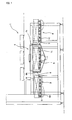
- Figure 1 is a front view showing the basic form of an ultrasonic washing equipment according to the invention
- Figure 2 a plan of the same
- Figure 3 a diagram illustrating one example of a shifting mechanism for an object to be washed
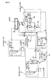
- Figure 4 a circuit diagram showing an example of cleaning liquid circuit of the washing equipment
- Figure 5 through Figure 10 diagrams illustrating multi-tank ultrasonic washing equipment.
- the ultrasonic washing equipment according to the invention is intended to make more efficient, for instance when putting works successively delivered from the machining line or the like to ultrasonic washing, the inputting and retrieval of the works in and out of the washing tank, and at the same to prevent the equipment from increasing in vertical size; it is configured as, for instance, as deburring /washing equipment for valve bodies, which are an automobile component item.
- this ultrasonic washing equipment is provided with a shift route 3 for putting works delivered from a machining line or the like (not shown) into a washing tank 2, the washing tank 2 for washing and deburring the works, and another the shift route 4 for discharging washed works from the washing tank 2.
- a carriage route 5 is also disposed within the washing tank 2, an inlet 6 closable with a door 6h is disposed in the side wall on the side upstream from the washing tank 2 (the feed shift route 3 side), and an outlet 7 closable with a door 7h is disposed in the side wall on the side downstream from the washing tank 2 (the discharge shift route 4 side).
- the shift routes 3 and 4 and the carriage route 5 are enabled to let carry a carrier 8, such as a basket, and a plurality of works can be accommodated within the carrier 8 and carried together as accommodated by the carrier 8.
- a rack member 10 is fitted to the under face of the carrier 8.
- the carrier 8 is moved by engaging this rack member 10 with a plurality each of pinions 11 disposed on the shift routes 3 and 4 and the carriage route 5 side and rotationally driving these pinions 11.
- An ultrasonic oscillator for emitting an ultrasonic wave toward the cleaning liquid is provided within the washing tank 2 and, as will be described afterwards, the cleaning liquid in the washing tank 2 can be replenished or discharged.
- the washing tank 2 is cleared of the cleaning liquid, the door 6h of the inlet 6 is opened, and the pinions 11 of the upstream shift route 3 and the pinions 11 of the carriage route 5 are rotationally driven to feed the carrier 8 into the washing tank 2.
- the door 6h of the inlet 6 is closed to let the cleaning liquid into the washing tank 2. Then an ultrasonic wave is emitted to deburry and wash the works.
- the washing tank 2 is provided with a cleaning liquid charging/discharging circuit 15 for charging and discharging the cleaning liquid in and out of the washing tank 2, an evacuating circuit 16 for making the interior of the washing tank 2 vacuum, a deaerating circuit 17 for deaerating the cleaning liquid, and a circulating circuit 18 for circulating the cleaning liquid in the washing tank 2.
- the cleaning liquid charging/discharging circuit 15 is provided with a storage tank 12 capable of supplying or receiving the cleaning liquid and a water charging/discharging line linking the washing tank 2 and the storage tank 12.
- the circulating circuit 18 circulates part of the cleaning liquid in the washing tank 2 with a circulating pump 21 and clears it of any dirt with a filter 22. Part of the cleaning liquid is deaerated by the deaerating circuit 17 connected midway on this circuit to be cleared of its gaseous content, and the deaerated cleaning liquid is returned to the washing tank 2.
- the deaerating circuit 17 When the cleaning liquid is in the washing tank 2 and circulating in the circulating circuit 18, the deaerating circuit 17 receives part of the circulating cleaning liquid in circulation and, after deaerating it, returns that pat of the liquid to the washing tank 2.
- the circuit receives part of the cleaning liquid in the storage tank 12 and, after deaerating, returns that pat of the liquid to the storage tank 12. Then by removing gases dissolved in the cleaning liquid, the impact of the cavity during the emission of the ultrasonic wave is increased.
- this deaerating circuit 17 is provided with a deaerating module 23, a vacuum pump 24, a circulating pump 25 and so forth.
- the cleaning liquid is sucked into the deaerating module 23 whose internal pressure has been reduced by the vacuum pump 24 and deaerated, and the removed gases are sucked by the vacuum pump 24 and discharged.
- the deaerated cleaning liquid is returned by the circulating pump 25 to either the storage tank 12 or the washing tank 2.
- the inlet 6 and the outlet 7 are designed in shape and size to permit the carrier 8 to pass, and the door 6h of the inlet 6 and the door 7h of the outlet 7 are enabled to move back and forth by the operation of a cylinder unit 27 as shown in Figure 2.
- the doors 6h and 7h move forward to the positions of the inlet 6 and the outlet 7, respectively, they can close the inlet 6 and the outlet 7 to seal the inside.
- they recede they can open the inlet 6 and the outlet 7.
- the cleaning liquid the washing tank 2 is shifted to the storage tank 12 via the water charging/discharging line of the cleaning liquid charging/discharging circuit 15 to prevent the cleaning liquid from flowing out even if the inlet 6 is opened. After that, the door 6h is opened and the pinions 11 of the shift route 3 and the carriage route 5 are rotationally driven. Then the carrier 8 is shifted into the washing tank 2 through the input 6.
- the door 6h is shut to close the inlet 6, and after evacuating the interior of the washing tank 2 with the evacuating circuit 16, the charging side valve of the water charging/discharging line of the cleaning liquid charging/discharging circuit 15 is opened to return the cleaning liquid in the storage tank 12 to the washing tank 2.
- the cleaning liquid has been deaerated within the storage tank 12 by the deaerating circuit 17, and the washing tank 2 is filled with the deaerated cleaning liquid.
- the liquid level is appropriately adjusted as required with a liquid level sensor or the like.
- a liquid level sensor or the like.
- the valve on the discharge side of the water charging/discharging line of the cleaning liquid charging/discharging circuit 15 is opened, the cleaning liquid in the washing tank 2 is shifted to the storage tank 12, and the liquid level is made lower than at the lower end of the outlet 7.
- the pinions 11 of the carriage route 5 and the pinions 11 of the downstream shift route 4 are driven, and the carrier 8 is discharged out of the washing tank 2.
- the door 7h is closed, the cycle returns to its first phase, and the same sequence is repeated.
- Figure 5 is a front view of the multi-tank ultrasonic washing equipment
- Figure 6 is a plan of the same
- Figure 7 illustrates a common door of adjoining tanks
- Figures 8 are drawings illustrating the way the door is opened and closed
- Figure 9 shows an example of cleaning liquid circuit of first and second preparatory tanks
- Figure 10 shows an example of cleaning liquid circuit of the washing tank.
- a first preparatory tank 31 and a second preparatory tank 32 are disposed on the upstream and downstream sides, respectively, of a carriage route with a washing tank 33 between them, the shift route 3 is arranged on the upstream side of the first preparatory tank 31, and the shift route 4 is arranged on the downstream side of the second preparatory tank 32.
- the carrier 8 carried from the upstream shift route 3 is fed into the washing tank 33 via the first preparatory tank 31 and, after going through ultrasonic washing for deburring in the washing tank 2, is discharged outside via the second preparatory tank 32.
- inlets 42 and outlets 43 are provided in the side walls of the first preparatory tank 31, the washing tank 33 and the second preparatory tank 32, and carriage routes 34 are disposed within the tanks 31, 32 and 33.
- An ultrasonic oscillator is arranged only in the washing tank 33 but not in the first preparatory tank 31 or the second preparatory tank 32, and cleaning liquid is charged into or discharge out of only the first preparatory tank 31 and the second preparatory tank 32, but the washing tank 33 holds cleaning liquid all the time.
- Cleaning liquid circuits of the first preparatory tank 31 and the second preparatory tank 32 are of substantially the same form. As shown in Figure 9, there are provided a cleaning liquid charging/discharging circuit 35 for charging or discharging the cleaning liquid into or out of the tanks 31 and 32, an evacuating circuit 36 for making the interior of the tanks 31 and 32 vacuum, a deaerating circuit 37 for deaerating the cleaning liquid, and a circulating circuit 38 for circulating the cleaning liquid in the tanks 31 and 32. These circuits are configured in the substantially same way as their respective counterparts in the foregoing embodiment with some partial exceptions.
- the cleaning liquid charging/discharging circuit 35 is provided with a storage tank 48 and so forth, and the evacuating circuit 36 is provided with a vacuum pump 50 and so forth.
- the deaerating circuit 37 is provided with a deaerating module 51, a vacuum pump 52, a circulating pump 53 and so forth, and the circulating circuit 38 is provided with a circulating pump 54, a filter 55 and so forth.
- the cleaning liquid circuit of the washing tank 33 is provided with a circulating circuit 39 for circulating the cleaning liquid and a deaerating circuit 40 for deaerating the cleaning liquid.
- a circulating circuit 39 for circulating the cleaning liquid
- a deaerating circuit 40 for deaerating the cleaning liquid.
- the circulating circuit 39 is provided with a circulating circuit 56, the filters 57 and so forth, and the deaerating circuit 40 is provided with a deaerating module 58, a vacuum pump 59, a circulating pump 60 and so forth.
- the outlet 43 of the first preparatory tank 31 and the inlet 42 of the washing tank 33 are disposed in mutually opposite positions, and so are the outlet 43 of the washing tank 33 and the inlet 42 of the second preparatory tank 32, and a common door 44 is provided between each couple of these tanks as shown in Figure 6. By opening or closing these doors 44, the outlet 43 and the inlet 42 are respectively caused to communicate with or intercepted from each other.
- each common door 44 is wedge-shaped and can be moved back and forth by the operation of a cylinder unit 45, while the inlet 42 or the outlet 43 is surrounded by a packing material 46 which can be inflated or submerged by elastic force.
- the first preparatory tank 31 is emptied by shifting the cleaning liquid in it to the storage tank 48, and the cleaning liquid is cleared of its gaseous contents by the deaerating circuit 37.
- the carrier 8 is conveyed from the upstream shift route 3, the carrier 8 is let in by opening the door 42h of the inlet 42 of the first preparatory tank 31.
- the door 42h When the carrier 8 is let into the first preparatory tank 31, the door 42h is closed to seal the inside, and after the pressure in the tank is reduced by the evacuating circuit 36, the valve on the charging side of the water charging/discharging line of the cleaning liquid charging/discharging circuit 35 is opened to let the cleaning liquid into the tank 31. And, after adjusting as required the liquid level to equalize it with that of the washing tank 33, the circulating circuit 38 is actuated to circulate the cleaning liquid, and the cleaning liquid is deaerated while being cleared of foreign matter by the filters.
- the operation of the circulating circuit 38 is stopped, and the work is shifted to the washing tank 33. Then, if the common door 44 between the first preparatory tank 31 and the washing tank 33 is opened, communication will be established between the tanks 31 and 33, and the carrier 8 will be fed into the washing tank 33 through the carriage routes 34 in the tanks 31 and 33.
- the carrier 8 is shifted into the second preparatory tank 32 in a similar procedure.
- the second preparatory tank 32 has been filled with cleaning liquid to a prescribed level in advance; when the carrier is fed into the second preparatory tank 32, the circulating circuit 38 of the second preparatory tank 32 is actuated to deaerated the cleaning liquid while clearing it of foreign matter.
- the cleaning liquid charging/discharging circuit 35 shifts the cleaning liquid to the storage tank 48, and after the tank 32 is cleared of cleaning liquid inside, the door 43h of the outlet 43 is opened to discharge the carrier 8.
- the number of tanks can be selected as desired, and the configuration of the cleaning liquid circuit in each tank is only illustrative.
- the shifting mechanism for the carrier 8 may be a cylinder or the like.
- the type of the works, the washing method, and other features can be selected as desired.
- the ultrasonic washing equipment according to the invention has an inlet and an outlet for charging and discharging the object to be washed into and out of the washing tank are provided in side walls of the washing tank of the ultrasonic washing equipment, and the object to be washed is charged and discharged sideways through these inlet and outlet, there is no need to move the object to be washed up and down, the works successively delivered from the machining line, and moreover the equipment is not increased in vertical size.
- a plurality of tanks in substantially the same shape as the washing tank are arranged along one line beside the inlet and outlet of the washing tank, their inlet and outlet are positioned opposite each other and a common door is disposed between the inlet and outlet, it is made possible to enhance the washing effect by the use of the plurality of tanks and to achieve a rinsing effect, moreover enabling the equipment to be reduced in size.
Landscapes
- Cleaning By Liquid Or Steam (AREA)
- Cleaning And De-Greasing Of Metallic Materials By Chemical Methods (AREA)
Abstract
This is an ultrasonic washing technique to enhance, when an object to be
washed is subjected to ultrasonic washing, the efficiency of charging and discharging
the object to be washed in and out of a washing tank while preventing the apparatus
from getting larger in the vertical direction. An inlet (6) and an outlet (7) are
provided on the side wall of the washing tank (2), with closable doors (6h) and (7h)
and, after the object to be washed (carrier (8)) carried along an upstream shift route
(3) is put in through the inlet (6), it is shut with the door (6h) for into a sealed closure,
cleaning liquid deaerated in a storage tank is let into a washing tank (2) to subject the
object to be washed to ultrasonic washing. After that, the cleaning liquid in the
washing tank (2) is returned to the storage tank and the door (7h) of the outlet (7) is
opened to discharge sideways the object to be washed (carrier (8)) through the outlet
(7) via a downstream shift route (4). And this operation is repeated.
Description
The present invention relates to an ultrasonic washing technique that allows
fast and efficient washing for deburring wheeled vehicle components or the like
which have been machined.
It is already known that complexly shaped automobile components, such as
valve bodies, which have been machined, can be very efficiently deburried by the
impact of powerful cavitation by ultrasonic washing, resulting in successful removal
of extremely small burrs. By a method generally used by such ultrasonic washing
equipment, an object to be washed is put into a washing tank containing cleaning
liquid from the top of the washing tank and, after the liquid is irradiated with an
ultrasonic wave to subject of the object to ultrasonic deburring, the object to be
washed is retrieved from the washing tank (see for instance Patent Document 1).
However, this method of putting the object to be washed into the washing
tank from above and retrieving it by pulling up involves a problem of incapable of
efficient washing of works which are successively delivered from the machining line
via a conveyance path or the like, such as components of wheeled vehicles, by
efficiently shifting them into or retrieving them out of the washing tank.
Moreover, in order to move the object to be washed up and down, the
equipment is inevitably increased in vertical size, and a lifting mechanism is also
needed for the works, entailing an additional equipment cost.
In view of this problem, an object of the present invention is to improve the
efficiency of putting and retrieving the object to be washed in and out of the washing
tank when it is to undergo ultrasonic washing and further to prevent the equipment
from increased in vertical size.
In order to achieve the object stated above, the invention provides ultrasonic
washing equipment intended for ultrasonic washing of an object to be washed by
putting it into a washing tank containing deaerated cleaning liquid, wherein an inlet
and an outlet for charging and discharging the object to be washed in and out of the
washing tank are provided in side walls of the washing tank, these inlet and outlet are
provided with closable doors, a shifting mechanism for an object to be washed
capable of charging the object to be washed into the washing tank from a side of the
washing tank and discharging the object to be washed in the washing tank toward a
side of the washing tank is provided in the vicinities of these inlet and outlet, and the
cleaning liquid in the washing tank is enabled by a cleaning liquid
charging/discharging mechanism to be charged into and discharged out of the
washing tank.
As stated in Claim 3, the object to be washed is put in from a side of the
washing tank through the inlet in the side wall of the washing tank, and after closing
the inlet with the door, deaerated cleaning liquid is let into the washing tank to
subject the object to be washed to ultrasonic washing, and after the washing and after
emptying the washing tank of the cleaning liquid and opening the door of the outlet
in the side wall of the washing tank, the object to be washed is discharged through
the outlet toward a side of the washing tank.
And if this operation is repeated, the works successively delivered from the
machining line can be efficiently washed, and moreover the equipment will not
increase in vertical size.
The way of opening and closing the doors of the inlet and the outlet here
among other features can be freely selected only if they can pass the object to be
washed in an open state and sealing the side of the washing tank in a closed state.
Also, the shifting mechanism for an object to be washed among other features
can be selected as desired; for instance a pinion-rack mechanism, a cylinder pressing
mechanism or some other system can be used.
Further, the specific configuration or the like of the cleaning liquid
charging/discharging mechanism can be selected as desired; for instance an
evacuation system, a pumping system or some other system can be used, though it is
preferable from the view point of shortening the cycle time to enable the cleaning
liquid to be charged or discharged in a short period of time.
Further according to the invention, a plurality of tanks of substantially the
same shape as the washing tank are arranged along one line beside the inlet and
outlet of the washing tank, the washing tank and these tanks adjoining each other are
disposed with their inlet and outlet arranged in mutually opposite positions, a
common door is provided between each couple of these inlet and outlet, and by
opening or closing these doors the outlet and inlet are enabled to communicate with
or intercepted from each other.
By arranging the washing tank the plurality of tanks along one line and
washing the object to be washed while it is successively shifted from the upstream
tank to the downstream tank, it is made possible to enhance, for instance, the
washing effect or the rinsing effect; if in this arrangement a common door is
provided between each couple of these inlet and outlet of the adjoining washing tank
and other tank, and the outlet and inlet are enabled to communicate with or
intercepted from each other by opening or closing these common doors, the object to
be washed can be smoothly shifted to another tank, so that works successively
delivered via a carriage route or the like can be smoothly washed. In addition, the
use of the common doors enable the equipment to be reduced in size.
Embodiments of the present invention will be described below with reference
to the accompanying drawings.
Here, Figure 1 is a front view showing the basic form of an ultrasonic
washing equipment according to the invention; Figure 2, a plan of the same; Figure 3,
a diagram illustrating one example of a shifting mechanism for an object to be
washed; Figure 4, a circuit diagram showing an example of cleaning liquid circuit of
the washing equipment; and Figure 5 through Figure 10, diagrams illustrating
multi-tank ultrasonic washing equipment.
The ultrasonic washing equipment according to the invention is intended to
make more efficient, for instance when putting works successively delivered from
the machining line or the like to ultrasonic washing, the inputting and retrieval of the
works in and out of the washing tank, and at the same to prevent the equipment from
increasing in vertical size; it is configured as, for instance, as deburring /washing
equipment for valve bodies, which are an automobile component item.
Thus, this ultrasonic washing equipment 1, as shown in Figure 1 and Figure 2,
is provided with a shift route 3 for putting works delivered from a machining line or
the like (not shown) into a washing tank 2, the washing tank 2 for washing and
deburring the works, and another the shift route 4 for discharging washed works
from the washing tank 2. A carriage route 5 is also disposed within the washing
tank 2, an inlet 6 closable with a door 6h is disposed in the side wall on the side
upstream from the washing tank 2 (the feed shift route 3 side), and an outlet 7
closable with a door 7h is disposed in the side wall on the side downstream from the
washing tank 2 (the discharge shift route 4 side).
The shift routes 3 and 4 and the carriage route 5 are enabled to let carry a
carrier 8, such as a basket, and a plurality of works can be accommodated within the
carrier 8 and carried together as accommodated by the carrier 8. In this
embodiment, as shown in Figure 3, a rack member 10 is fitted to the under face of
the carrier 8. The carrier 8 is moved by engaging this rack member 10 with a
plurality each of pinions 11 disposed on the shift routes 3 and 4 and the carriage
route 5 side and rotationally driving these pinions 11.
An ultrasonic oscillator for emitting an ultrasonic wave toward the cleaning
liquid is provided within the washing tank 2 and, as will be described afterwards, the
cleaning liquid in the washing tank 2 can be replenished or discharged.
The washing tank 2 is cleared of the cleaning liquid, the door 6h of the inlet 6
is opened, and the pinions 11 of the upstream shift route 3 and the pinions 11 of the
carriage route 5 are rotationally driven to feed the carrier 8 into the washing tank 2.
When the feeding is completed, the door 6h of the inlet 6 is closed to let the cleaning
liquid into the washing tank 2. Then an ultrasonic wave is emitted to deburry and
wash the works.
When the washing is completed, the cleaning liquid is discharged and the
door 7h of the outlet 7 is opened, the pinions 11 of the carriage route 5 and the
pinions 11 of the downstream shift route 4 are rotationally driven to discharge the
carrier 8 out of the washing tank 2.
One example of cleaning liquid circuit of the washing tank 2 will be described
with reference to Figure 4.
The washing tank 2 is provided with a cleaning liquid charging/discharging
circuit 15 for charging and discharging the cleaning liquid in and out of the washing
tank 2, an evacuating circuit 16 for making the interior of the washing tank 2 vacuum,
a deaerating circuit 17 for deaerating the cleaning liquid, and a circulating circuit 18
for circulating the cleaning liquid in the washing tank 2. The cleaning liquid
charging/discharging circuit 15 is provided with a storage tank 12 capable of
supplying or receiving the cleaning liquid and a water charging/discharging line
linking the washing tank 2 and the storage tank 12.
When a valve on the discharging side of the water charging/discharging line
of the cleaning liquid charging/discharging circuit 15, the cleaning liquid in the
washing tank 2 is discharged by its own weight into the storage tank 12. When the
cleaning liquid in the storage tank 12 is to be returned into the washing tank 2, a
valve on the charging side of the water charging/discharging line is opened after
reducing the pressure within the washing tank 2 by working the vacuum pump 20 of
the evacuating circuit 16, and the cleaning liquid is sucked into the washing tank 2.
When the pressure in the washing tank 2 is to be restored to the atmospheric
level, the valve of an atmospheric opening line 26 is opened.
The circulating circuit 18 circulates part of the cleaning liquid in the washing
tank 2 with a circulating pump 21 and clears it of any dirt with a filter 22. Part of
the cleaning liquid is deaerated by the deaerating circuit 17 connected midway on
this circuit to be cleared of its gaseous content, and the deaerated cleaning liquid is
returned to the washing tank 2.
When the cleaning liquid is in the washing tank 2 and circulating in the
circulating circuit 18, the deaerating circuit 17 receives part of the circulating
cleaning liquid in circulation and, after deaerating it, returns that pat of the liquid to
the washing tank 2. When the cleaning liquid is in the storage tank 12, the circuit
receives part of the cleaning liquid in the storage tank 12 and, after deaerating,
returns that pat of the liquid to the storage tank 12. Then by removing gases
dissolved in the cleaning liquid, the impact of the cavity during the emission of the
ultrasonic wave is increased.
For this purpose, this deaerating circuit 17 is provided with a deaerating
module 23, a vacuum pump 24, a circulating pump 25 and so forth. The cleaning
liquid is sucked into the deaerating module 23 whose internal pressure has been
reduced by the vacuum pump 24 and deaerated, and the removed gases are sucked by
the vacuum pump 24 and discharged. The deaerated cleaning liquid is returned by
the circulating pump 25 to either the storage tank 12 or the washing tank 2.
The inlet 6 and the outlet 7 are designed in shape and size to permit the carrier
8 to pass, and the door 6h of the inlet 6 and the door 7h of the outlet 7 are enabled to
move back and forth by the operation of a cylinder unit 27 as shown in Figure 2.
When the doors 6h and 7h move forward to the positions of the inlet 6 and the outlet
7, respectively, they can close the inlet 6 and the outlet 7 to seal the inside. When
they recede, they can open the inlet 6 and the outlet 7.
The actions and other aspects of the ultrasonic washing equipment 1 will now
be described.
When the carrier 8 is to be fed into the washing tank 2, the cleaning liquid the
washing tank 2 is shifted to the storage tank 12 via the water charging/discharging
line of the cleaning liquid charging/discharging circuit 15 to prevent the cleaning
liquid from flowing out even if the inlet 6 is opened. After that, the door 6h is
opened and the pinions 11 of the shift route 3 and the carriage route 5 are rotationally
driven. Then the carrier 8 is shifted into the washing tank 2 through the input 6.
Then, the door 6h is shut to close the inlet 6, and after evacuating the interior
of the washing tank 2 with the evacuating circuit 16, the charging side valve of the
water charging/discharging line of the cleaning liquid charging/discharging circuit 15
is opened to return the cleaning liquid in the storage tank 12 to the washing tank 2.
By then, the cleaning liquid has been deaerated within the storage tank 12 by
the deaerating circuit 17, and the washing tank 2 is filled with the deaerated cleaning
liquid.
After the internal pressure of the washing tank 2 is returned to the
atmospheric level by opening the valve of the atmospheric opening line 26, the liquid
level is appropriately adjusted as required with a liquid level sensor or the like.
When an ultrasonic wave is emitted by the ultrasonic oscillator into the cleaning
liquid, a powerful cavity is generated in the cleaning liquid, and the heavy impact of
this cavity removes burrs.
In this while the cleaning liquid in the washing tank 2 is circulated by the
circulating circuit 18, cleared of any dirt by the filter 22 and of any dissolved gases
by the deaerating circuit 17, and the heavy impact of the cavity is thereby
maintained.
When ultrasonic washing for deburring is completed, the valve on the
discharge side of the water charging/discharging line of the cleaning liquid
charging/discharging circuit 15 is opened, the cleaning liquid in the washing tank 2 is
shifted to the storage tank 12, and the liquid level is made lower than at the lower
end of the outlet 7. After the door 7h of the outlet 7 is opened, the pinions 11 of the
carriage route 5 and the pinions 11 of the downstream shift route 4 are driven, and
the carrier 8 is discharged out of the washing tank 2. When the discharging ends,
the door 7h is closed, the cycle returns to its first phase, and the same sequence is
repeated.
The works successively delivered from upstream can be efficiently washed in
the procedure described above, and no extra trouble is involved in either charging
into or discharging out of the washing tank 2.
Next will be described an example of configuration of multi-tank type
ultrasonic washing equipment will be described with reference to Figure 5 through
Figure 9.
Here, Figure 5 is a front view of the multi-tank ultrasonic washing equipment;
Figure 6 is a plan of the same; Figure 7 illustrates a common door of adjoining tanks;
Figures 8 are drawings illustrating the way the door is opened and closed; Figure 9
shows an example of cleaning liquid circuit of first and second preparatory tanks;
and Figure 10 shows an example of cleaning liquid circuit of the washing tank.
In this example of configuration, a first preparatory tank 31 and a second
preparatory tank 32 are disposed on the upstream and downstream sides, respectively,
of a carriage route with a washing tank 33 between them, the shift route 3 is arranged
on the upstream side of the first preparatory tank 31, and the shift route 4 is arranged
on the downstream side of the second preparatory tank 32.
And the carrier 8 carried from the upstream shift route 3 is fed into the
washing tank 33 via the first preparatory tank 31 and, after going through ultrasonic
washing for deburring in the washing tank 2, is discharged outside via the second
preparatory tank 32.
For this purpose, inlets 42 and outlets 43 are provided in the side walls of the
first preparatory tank 31, the washing tank 33 and the second preparatory tank 32,
and carriage routes 34 are disposed within the tanks 31, 32 and 33. An ultrasonic
oscillator is arranged only in the washing tank 33 but not in the first preparatory tank
31 or the second preparatory tank 32, and cleaning liquid is charged into or discharge
out of only the first preparatory tank 31 and the second preparatory tank 32, but the
washing tank 33 holds cleaning liquid all the time.
Cleaning liquid circuits of the first preparatory tank 31 and the second
preparatory tank 32 are of substantially the same form. As shown in Figure 9, there
are provided a cleaning liquid charging/discharging circuit 35 for charging or
discharging the cleaning liquid into or out of the tanks 31 and 32, an evacuating
circuit 36 for making the interior of the tanks 31 and 32 vacuum, a deaerating circuit
37 for deaerating the cleaning liquid, and a circulating circuit 38 for circulating the
cleaning liquid in the tanks 31 and 32. These circuits are configured in the
substantially same way as their respective counterparts in the foregoing embodiment
with some partial exceptions.
For instance, the cleaning liquid charging/discharging circuit 35 is provided
with a storage tank 48 and so forth, and the evacuating circuit 36 is provided with a
vacuum pump 50 and so forth. The deaerating circuit 37 is provided with a
deaerating module 51, a vacuum pump 52, a circulating pump 53 and so forth, and
the circulating circuit 38 is provided with a circulating pump 54, a filter 55 and so
forth.
The cleaning liquid circuit of the washing tank 33, as shown in Figure 10, is
provided with a circulating circuit 39 for circulating the cleaning liquid and a
deaerating circuit 40 for deaerating the cleaning liquid. As the circulating circuit 39
circulates the cleaning liquid in the washing tank 33, the liquid is deaerated by the
deaerating circuit 40 while being cleared of foreign matter and the like by filters 57,
and the impact of the cavity is thereby increased.
For this purpose, the circulating circuit 39 is provided with a circulating
circuit 56, the filters 57 and so forth, and the deaerating circuit 40 is provided with a
deaerating module 58, a vacuum pump 59, a circulating pump 60 and so forth.
Incidentally, the outlet 43 of the first preparatory tank 31 and the inlet 42 of
the washing tank 33 are disposed in mutually opposite positions, and so are the outlet
43 of the washing tank 33 and the inlet 42 of the second preparatory tank 32, and a
common door 44 is provided between each couple of these tanks as shown in Figure
6. By opening or closing these doors 44, the outlet 43 and the inlet 42 are
respectively caused to communicate with or intercepted from each other.
Thus, as is evident from Figure 6 and Figure 7, each common door 44 is
wedge-shaped and can be moved back and forth by the operation of a cylinder unit
45, while the inlet 42 or the outlet 43 is surrounded by a packing material 46 which
can be inflated or submerged by elastic force.
And as shown in Figure 8(a), when a common door 44 advances toward the
fronts of an inlet 42 and an outlet 43, the communication is intercepted to seal the
inside; as shown in Figure 8(b), when the door 44 recedes from the fronts of the inlet
42 and the outlet 43, the packing materials 46 on both sides inflate to establish
communication between the inlet 42 and the outlet 43 to prevent the liquid from
leaking out.
The washing method in the ultrasonic washing equipment described above
will be described.
The first preparatory tank 31 is emptied by shifting the cleaning liquid in it to
the storage tank 48, and the cleaning liquid is cleared of its gaseous contents by the
deaerating circuit 37. When the carrier 8 is conveyed from the upstream shift route
3, the carrier 8 is let in by opening the door 42h of the inlet 42 of the first preparatory
tank 31.
When the carrier 8 is let into the first preparatory tank 31, the door 42h is
closed to seal the inside, and after the pressure in the tank is reduced by the
evacuating circuit 36, the valve on the charging side of the water
charging/discharging line of the cleaning liquid charging/discharging circuit 35 is
opened to let the cleaning liquid into the tank 31. And, after adjusting as required
the liquid level to equalize it with that of the washing tank 33, the circulating circuit
38 is actuated to circulate the cleaning liquid, and the cleaning liquid is deaerated
while being cleared of foreign matter by the filters.
When the work is cleared of sticking foreign matter and the cleaning liquid
has been deaerated to a desired level, the operation of the circulating circuit 38 is
stopped, and the work is shifted to the washing tank 33. Then, if the common door
44 between the first preparatory tank 31 and the washing tank 33 is opened,
communication will be established between the tanks 31 and 33, and the carrier 8
will be fed into the washing tank 33 through the carriage routes 34 in the tanks 31
and 33.
And when the carrier 33 is fed into the washing tank 33, the common doors
44 is closed to seal the inside, and ultrasonic washing is started.
When the ultrasonic washing in the washing tank 33 is completed, the carrier
8 is shifted into the second preparatory tank 32 in a similar procedure. When the
common door 44 between the washing tank 33 and the second preparatory tank 32 is
to be opened in this process, the second preparatory tank 32 has been filled with
cleaning liquid to a prescribed level in advance; when the carrier is fed into the
second preparatory tank 32, the circulating circuit 38 of the second preparatory tank
32 is actuated to deaerated the cleaning liquid while clearing it of foreign matter.
After a rinsing effect has been achieved, the cleaning liquid charging/discharging
circuit 35 shifts the cleaning liquid to the storage tank 48, and after the tank 32 is
cleared of cleaning liquid inside, the door 43h of the outlet 43 is opened to discharge
the carrier 8.
And by repeating this operation in the tanks 31, 33 and 32, the works
successively delivered to them can be efficiently washed in a cyclic process.
To add, the present invention is not limited to the embodiments described
above. What has substantially the same configuration and exerts substantially the
same effect as what is described in the Claims of the invention belongs to the
technical scope of the invention.
For instance, the number of tanks can be selected as desired, and the
configuration of the cleaning liquid circuit in each tank is only illustrative. Also,
the shifting mechanism for the carrier 8 may be a cylinder or the like. Further, the
type of the works, the washing method, and other features can be selected as desired.
Since the ultrasonic washing equipment according to the invention has an
inlet and an outlet for charging and discharging the object to be washed into and out
of the washing tank are provided in side walls of the washing tank of the ultrasonic
washing equipment, and the object to be washed is charged and discharged sideways
through these inlet and outlet, there is no need to move the object to be washed up
and down, the works successively delivered from the machining line, and moreover
the equipment is not increased in vertical size.
Further, if a plurality of tanks in substantially the same shape as the washing
tank are arranged along one line beside the inlet and outlet of the washing tank, their
inlet and outlet are positioned opposite each other and a common door is disposed
between the inlet and outlet, it is made possible to enhance the washing effect by the
use of the plurality of tanks and to achieve a rinsing effect, moreover enabling the
equipment to be reduced in size.
Claims (3)
- Ultrasonic washing equipment intended for ultrasonic washing of an object to be washed by putting it into a washing tank containing deaerated cleaning liquid, characterized in that an inlet and an outlet for charging and discharging the object to be washed in and out of the washing tank are provided in side walls of said washing tank, these inlet and outlet are provided with closable doors, a shifting mechanism for an object to be washed capable of charging the object to be washed into the washing tank from a side of the washing tank and discharging the object to be washed in the washing tank toward a side of the washing tank is provided in the vicinities of these inlet and outlet, and the cleaning liquid in said washing tank is enabled by a cleaning liquid charging/discharging mechanism to be charged into and discharged out of the washing tank.
- The ultrasonic washing equipment according to claim 1, characterized in that a plurality of tanks of substantially the same shape as the washing tank are arranged along one line beside the inlet and outlet of said washing tank, the washing tank and these tanks adjoining each other are disposed with their inlet and outlet arranged in mutually opposite positions, a common door is provided between each couple of these inlet and outlet, and by opening or closing these doors said outlet and inlet are enabled to communicate with or intercepted from each other.
- An ultrasonic washing method characterized in that it comprises a step of putting an object to be washed from a side of a washing tank through an inlet in a side wall of the washing tank and, after closing the inlet with a door, letting deaerated cleaning liquid into the washing tank, a step of subjecting the object to be washed to ultrasonic washing within the washing tank, and a step of discharging the object to be washed through the outlet toward a side of the washing tank after the washing and after emptying the washing tank of the cleaning liquid and opening the door of an outlet in a side wall of the washing tank.
Applications Claiming Priority (3)
| Application Number | Priority Date | Filing Date | Title |
|---|---|---|---|
| JP2002293252A JP4129484B2 (en) | 2002-10-07 | 2002-10-07 | Ultrasonic cleaning apparatus and ultrasonic cleaning method |
| JP2002293252 | 2002-10-07 | ||
| PCT/JP2003/012833 WO2004030838A1 (en) | 2002-10-07 | 2003-10-07 | Ultrsonic washing equipment and ultrasonic washing method |
Publications (2)
| Publication Number | Publication Date |
|---|---|
| EP1557224A1 true EP1557224A1 (en) | 2005-07-27 |
| EP1557224A4 EP1557224A4 (en) | 2007-06-13 |
Family
ID=32064002
Family Applications (1)
| Application Number | Title | Priority Date | Filing Date |
|---|---|---|---|
| EP03751361A Withdrawn EP1557224A4 (en) | 2002-10-07 | 2003-10-07 | ULTRASONIC WASHING EQUIPMENT AND ULTRASONIC WASHING METHOD |
Country Status (7)
| Country | Link |
|---|---|
| US (1) | US20060137727A1 (en) |
| EP (1) | EP1557224A4 (en) |
| JP (1) | JP4129484B2 (en) |
| CN (1) | CN1723091A (en) |
| AU (1) | AU2003271113A1 (en) |
| CA (1) | CA2501592A1 (en) |
| WO (1) | WO2004030838A1 (en) |
Families Citing this family (13)
| Publication number | Priority date | Publication date | Assignee | Title |
|---|---|---|---|---|
| DE102006022831A1 (en) * | 2006-05-16 | 2007-11-22 | Siemens Ag | Method of controlling a grinding machine and numerically controlled grinding machine |
| JP5086123B2 (en) * | 2008-02-15 | 2012-11-28 | 株式会社ディスコ | Processing waste liquid treatment equipment |
| JP5149035B2 (en) * | 2008-02-28 | 2013-02-20 | 株式会社ディスコ | Processing waste liquid treatment equipment |
| CN102671883A (en) * | 2012-05-18 | 2012-09-19 | 上海思恩电子技术(东台)有限公司 | Cleaning machine with supporting and thrusting mechanism |
| CN105983553A (en) * | 2015-05-18 | 2016-10-05 | 张家港市超声电气有限公司 | Ultrasonic cleaning device and cleaning method |
| CN108014647A (en) * | 2017-12-26 | 2018-05-11 | 苏州市华测检测技术有限公司 | The ultrasonic cleaning apparatus of bioxin sampling membrane |
| CN108325932B (en) * | 2018-02-01 | 2024-04-02 | 长安大学 | Full-automatic rotating film oven sample bottle cleaning instrument |
| JP2019181355A (en) * | 2018-04-06 | 2019-10-24 | 株式会社ブルー・スターR&D | Ultrasonic cleaning method and ultrasonic cleaning device of object to be cleaned |
| CN108246709B (en) * | 2018-04-16 | 2023-07-14 | 绵阳市朝育机械有限公司 | A degreasing and cleaning system |
| CN109201596B (en) * | 2018-09-03 | 2021-01-15 | 贵州华旭光电技术有限公司 | Liquid crystal screen cleaning device |
| CN109868482A (en) * | 2019-03-11 | 2019-06-11 | 常德力元新材料有限责任公司 | A kind of preparation system and method for Punching steel strip |
| CN112642795B (en) * | 2020-12-01 | 2022-05-10 | 哈尔滨岛田大鹏工业股份有限公司 | Energy-saving ultrasonic cleaner |
| CN112775099A (en) * | 2021-01-27 | 2021-05-11 | 南京工业职业技术大学 | Spare part belt cleaning device is used in new energy automobile production |
Family Cites Families (16)
| Publication number | Priority date | Publication date | Assignee | Title |
|---|---|---|---|---|
| CH355336A (en) * | 1957-12-11 | 1961-06-30 | Technochemie Ag | Process for cleaning metal parts |
| DE2013939A1 (en) * | 1970-03-24 | 1971-10-07 | Eser U | Machine part washing device |
| DE3002472C2 (en) * | 1980-01-24 | 1982-03-04 | Interatom Internationale Atomreaktorbau Gmbh, 5060 Bergisch Gladbach | Method and device for cleaning workpieces wetted with alkali metal |
| JP3030313B2 (en) * | 1992-02-12 | 2000-04-10 | 住特フェライト株式会社 | Continuous ultrasonic cleaning equipment |
| JPH05315313A (en) * | 1992-05-07 | 1993-11-26 | Fujitsu Ltd | Leaf-type ultrasonic processing equipment |
| JP2897537B2 (en) * | 1992-06-16 | 1999-05-31 | 日本電気株式会社 | Substrate cleaning device |
| DE4220927C2 (en) * | 1992-06-25 | 1994-08-18 | Werner Meisner | Method and device for transporting cleaning containers for soiled objects in a washing system |
| DE4317862A1 (en) * | 1993-05-28 | 1994-12-01 | Aichelin Ind Ofen | Method and device for cleaning metallic workpieces |
| TW318190B (en) * | 1993-10-06 | 1997-10-21 | Hitachi Shipbuilding Eng Co | |
| JPH09253592A (en) * | 1996-03-25 | 1997-09-30 | Ii M Ii:Kk | Completely sealed cleaning device |
| JPH10335294A (en) * | 1997-06-05 | 1998-12-18 | Toshiba Corp | Substrate cleaning apparatus, cleaning method, and semiconductor device manufactured using the method |
| US6307184B1 (en) * | 1999-07-12 | 2001-10-23 | Fsi International, Inc. | Thermal processing chamber for heating and cooling wafer-like objects |
| JP2001170583A (en) * | 1999-12-15 | 2001-06-26 | Kanegafuchi Chem Ind Co Ltd | Ultrasonic cleaning device and ultrasonic cleaning method |
| JP2001332523A (en) * | 2000-05-19 | 2001-11-30 | Dainippon Screen Mfg Co Ltd | Substrate processing equipment |
| JP2001340820A (en) * | 2000-05-31 | 2001-12-11 | Shibaura Mechatronics Corp | Ultrasonic cleaning equipment |
| US6659116B1 (en) * | 2000-06-26 | 2003-12-09 | Lam Research Corporation | System for wafer carrier in-process clean and rinse |
-
2002
- 2002-10-07 JP JP2002293252A patent/JP4129484B2/en not_active Expired - Fee Related
-
2003
- 2003-10-07 EP EP03751361A patent/EP1557224A4/en not_active Withdrawn
- 2003-10-07 US US10/530,623 patent/US20060137727A1/en not_active Abandoned
- 2003-10-07 CN CNA2003801053241A patent/CN1723091A/en active Pending
- 2003-10-07 CA CA002501592A patent/CA2501592A1/en not_active Abandoned
- 2003-10-07 AU AU2003271113A patent/AU2003271113A1/en not_active Abandoned
- 2003-10-07 WO PCT/JP2003/012833 patent/WO2004030838A1/en not_active Ceased
Also Published As
| Publication number | Publication date |
|---|---|
| CN1723091A (en) | 2006-01-18 |
| US20060137727A1 (en) | 2006-06-29 |
| WO2004030838A1 (en) | 2004-04-15 |
| JP2004122064A (en) | 2004-04-22 |
| EP1557224A4 (en) | 2007-06-13 |
| CA2501592A1 (en) | 2004-04-15 |
| AU2003271113A8 (en) | 2004-04-23 |
| JP4129484B2 (en) | 2008-08-06 |
| AU2003271113A1 (en) | 2004-04-23 |
Similar Documents
| Publication | Publication Date | Title |
|---|---|---|
| US20060137727A1 (en) | Ultrasonic washing apparatus and ultrasonic washing method | |
| US20080196741A1 (en) | Washing device and its work conveying method | |
| CZ264099A3 (en) | Industrial cleaning equipment | |
| AU753719B2 (en) | Chip conveyor and chip separating and collecting device used for the chip conveyor | |
| JP6437949B2 (en) | Emulsion cleaning device | |
| KR20230034232A (en) | Processing Stations, Processing Plants, and Methods for Processing Workpieces | |
| US5276998A (en) | Method and apparatus for washing and cleaning a workpiece | |
| MX2009002001A (en) | Cleaning device having a flood chamber. | |
| JP2966240B2 (en) | Electric discharge machine | |
| JPH05263459A (en) | Suction pressure vessel | |
| CN216785009U (en) | Processing apparatus for processing workpieces | |
| CN114453313A (en) | Method for removing oil wax from metal | |
| JPH0796233B2 (en) | Water cleaning device for molding dies | |
| CN112719267A (en) | Large-scale 3D metal printing complete machine powder circulation system with workpiece taking station function and circulation method thereof | |
| KR100594345B1 (en) | Cleaning equipment | |
| JP2017170425A (en) | Workpiece cleaning method and workpiece cleaning device | |
| US3350224A (en) | Washing small parts | |
| KR20030090425A (en) | Vehicle to clean water collecting tanks | |
| JP2002147178A (en) | Tunnel excavator dumping equipment | |
| CN112193212B (en) | Internal glass cleaning device for excavator and use method | |
| JP2598914Y2 (en) | Washing and transporting equipment for dredged soil | |
| CN105016093B (en) | A kind of container of bulk transportation unloads case apparatus | |
| KR200375905Y1 (en) | Washing Device for Worked Machine parts | |
| KR101911648B1 (en) | Apparatus for cleaning the engine of car | |
| CN224222144U (en) | Through type vacuum cleaner |
Legal Events
| Date | Code | Title | Description |
|---|---|---|---|
| PUAI | Public reference made under article 153(3) epc to a published international application that has entered the european phase |
Free format text: ORIGINAL CODE: 0009012 |
|
| 17P | Request for examination filed |
Effective date: 20050407 |
|
| AK | Designated contracting states |
Kind code of ref document: A1 Designated state(s): AT BE BG CH CY CZ DE DK EE ES FI FR GB GR HU IE IT LI LU MC NL PT RO SE SI SK TR |
|
| AX | Request for extension of the european patent |
Extension state: AL LT LV MK |
|
| DAX | Request for extension of the european patent (deleted) | ||
| A4 | Supplementary search report drawn up and despatched |
Effective date: 20070511 |
|
| STAA | Information on the status of an ep patent application or granted ep patent |
Free format text: STATUS: THE APPLICATION HAS BEEN WITHDRAWN |
|
| 18W | Application withdrawn |
Effective date: 20080222 |