EP1557113A1 - Schliessvorrichtung, insbesondere für Möbelschubladen - Google Patents
Schliessvorrichtung, insbesondere für Möbelschubladen Download PDFInfo
- Publication number
- EP1557113A1 EP1557113A1 EP05000300A EP05000300A EP1557113A1 EP 1557113 A1 EP1557113 A1 EP 1557113A1 EP 05000300 A EP05000300 A EP 05000300A EP 05000300 A EP05000300 A EP 05000300A EP 1557113 A1 EP1557113 A1 EP 1557113A1
- Authority
- EP
- European Patent Office
- Prior art keywords
- locking device
- drawer
- spring
- biasing
- rail
- Prior art date
- Legal status (The legal status is an assumption and is not a legal conclusion. Google has not performed a legal analysis and makes no representation as to the accuracy of the status listed.)
- Granted
Links
Images


Classifications
-
- A—HUMAN NECESSITIES
- A47—FURNITURE; DOMESTIC ARTICLES OR APPLIANCES; COFFEE MILLS; SPICE MILLS; SUCTION CLEANERS IN GENERAL
- A47B—TABLES; DESKS; OFFICE FURNITURE; CABINETS; DRAWERS; GENERAL DETAILS OF FURNITURE
- A47B88/00—Drawers for tables, cabinets or like furniture; Guides for drawers
- A47B88/40—Sliding drawers; Slides or guides therefor
- A47B88/453—Actuated drawers
- A47B88/46—Actuated drawers operated by mechanically-stored energy, e.g. by springs
- A47B88/467—Actuated drawers operated by mechanically-stored energy, e.g. by springs self-closing
-
- E—FIXED CONSTRUCTIONS
- E05—LOCKS; KEYS; WINDOW OR DOOR FITTINGS; SAFES
- E05Y—INDEXING SCHEME ASSOCIATED WITH SUBCLASSES E05D AND E05F, RELATING TO CONSTRUCTION ELEMENTS, ELECTRIC CONTROL, POWER SUPPLY, POWER SIGNAL OR TRANSMISSION, USER INTERFACES, MOUNTING OR COUPLING, DETAILS, ACCESSORIES, AUXILIARY OPERATIONS NOT OTHERWISE PROVIDED FOR, APPLICATION THEREOF
- E05Y2201/00—Constructional elements; Accessories therefor
- E05Y2201/40—Motors; Magnets; Springs; Weights; Accessories therefor
- E05Y2201/404—Function thereof
- E05Y2201/41—Function thereof for closing
- E05Y2201/412—Function thereof for closing for the final closing movement
Definitions
- the invention relates to a locking device, in particular for furniture drawers according to the preamble of independent claim 1.
- Closures for furniture drawers are already numerous from the state known in the art, which is a uniform and / or complete closing allow the drawer.
- the object of the present invention is a locking device as Automatic closure, in particular for furniture drawers, so to shape and to develop, which better to different weights of the movable Furniture parts can be customized.
- the locking device a Automatic retraction is, with the biasing force of the energy storage before or during or after installation of automatic retraction in the guide or the Drawer is adjustable and for adjusting the biasing force of the Energy storage at least one separate Vorencies- or adjustment is provided, wherein the energy storage at least one compression spring or Tension spring includes, whose axial length by the bias or Adjustment is changeable.
- the advantage here is that the biasing force of the energy store depends on the load Drawer may be dependent, which affects the closing of the drawer and that a more variable and sensitive adjustment of the biasing force of the Energy storage can take place in the form of a compression or tension spring, as in Compared to other types of springs with compression or tension springs on the one hand the Spring constant is relatively low, on the other hand, the Einstellwegs Colour relatively large is. In addition, if a damping system is present, it is also advantageous that the closing forces of both systems can be optimized.
- An energy store with more biasing force is preferably for heavy Suitable for drawers.
- An energy storage with less biasing force is preferably used in light drawers.
- the energy store is a Compression spring, wherein a plunger acts as a guide element for this compression spring, the is mounted between ram end and coupling device.
- the energy store is a Mainspring.
- the tension spring is between this element and the coupling device assembled.
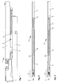
- FIGS. 1 to 6 show several embodiments of a retraction automatic 5 as a closing device with a compression spring 8 as an energy store.
- Fig. 1 the drawer slide 1 is shown in the closed position.
- the Automatic retraction 5 is mounted on the carcass rail 4.
- the driving pin 6 is connected to the drawer rail 2. He is from the coupling device 21st the automatic intake 5 seized.
- the drawer slide 1 can also be a Middle rail 3 between the drawer rail 2 and the carcass rail 4th exhibit.
- Fig. 2 shows an automatic retraction 5, which belongs to the prior art.
- the Compression spring 8 is on the plunger 9 between the wedge 10 and the plate 23rd held, or pressed with bias.
- the wedge 10 is located at the end of the plunger 9th
- Fig. 3 is a first variant for the adjustment of the biasing force of Compression spring 8 shown.
- a biasing element 11 is between the wedge 10 and the end of the plunger 9 mounted.
- the compression spring 8 is more biased as the compression spring 8 of Fig. 2.
- Such a retraction 5 is rather used for a heavy duty drawer. It would be possible, To use biasing elements 11 with different lengths, and / or to combine several together and / or the biasing member 11 axially slidable in the housing 7 of the automatic intake 5 to make it in different positions can be locked.
- Fig. 4 is a second variant for the adjustment of the biasing force shown.
- the plunger 9 has axially spaced holes 12 at its End portion, wherein the wedge 10 also has a hole 12, in which a pin 13 releasably transversely or obliquely engages the longitudinal axis and the wedge 10 with the plunger 9 in the desired preload length fixed.
- Fig. 5 and Fig. 6 is a third variant for the adjustment of Biasing force shown.
- the plunger 9 is shorter than the plunger of Figures 1-4 and axially drilled at its free end and in this bore 15 is a Internal thread introduced.
- a screw 14 is mounted in the bore 15. For a heavy drawer, the screw 14 is preferably complete screwed in (Fig. 5) and for a light drawer, the position of Fig. 6 prefers.
- FIGS. 7 to 10 show embodiments of an automatic retraction mechanism 5 as Closing device shown with a tension spring 22 as energy storage.
- Fig. 7 and Fig. 8 the drawer slide 1 is shown in the closed position.
- the automatic intake 5 is mounted on the carcass rail 4.
- the driving pin 6 is connected to the drawer rail 2. He is gripped by the coupling device 21 of the automatic retraction 5.
- a biasing element 16 is fixed.
- the tension spring 22 is fixed between the bottom 16 a of the biasing member 16 and the coupling device 21.
- the biasing element 16 has a plurality of latching positions. For example, in Fig. 7, the axially forward locking edge 17 of the rear appendage portion 16b of the biasing member 16 rests on the rear end face 19 of the body rail 4, for a minimum biasing force of the tension spring 22.
- Fig. 7 the axially forward locking edge 17 of the rear appendage portion 16b of the biasing member 16 rests on the rear end face 19 of the body rail 4, for a minimum biasing force of the tension spring 22.
- the length of the housing 7 is for the smallest desired Bias force of the tension spring 22 should fit. Larger preload forces be by pushing apart of the biasing element 16 and the Housing 7, as well as locking the biasing element 16 reaches.
- Fig. 11 and Fig. 12 is another embodiment of an automatic retraction 5 shown as a closing device with a tension spring 22 as energy storage, wherein the biasing element 16 is mounted in the housing 7 of the automatic retraction 5 / is locked.
- the housing 7 has at least two holes 24 in which the block 25 of the Biasing element 16 stores.
- the biasing element 16 is in Housing 7 guided axially displaceable.
- the biasing force of the tension spring 22 is greater for the automatic retraction 5 of 11 as for the automatic feed 5 of FIG. 12th
Landscapes
- Engineering & Computer Science (AREA)
- Mechanical Engineering (AREA)
- Drawers Of Furniture (AREA)
Abstract
Description
- Ein zusätzlicher Teil wird zwischen Stößelende und Druckfeder montiert.
- Der Stößel hat mehrere Rastpositionen, in denen das Stößelende fixiert wird.
- Das Stößelende ist als Schraube ausgebildet.
- Fig. 1 :
- Seitenansicht einer Schubladenführung mit einer ersten Schließvorrichtung;
- Fig. 2 :
- Ansicht von oben einer bekannten Ausführungsform einer Einzugsautomatik;
- Fig. 3 :
- Ansicht von oben eines ersten Beispiels der erfindungsgemäßen Einzugsautomatik;
- Fig. 4 :
- Ansicht von oben eines zweiten Beispiels der erfindungsgemäßen Einzugsautomatik;
- Fig. 5 :
- Ansicht von oben eines dritten Beispiels der erfindungsgemäßen Einzugsautomatik in einer ersten Position;
- Fig. 6 :
- Ansicht von oben eines dritten Beispiels der erfindungsgemäßen Einzugsautomatik in einer zweiten Position;
- Fig. 7 :
- Seitenansicht einer Schubladenführung mit einer zweiten Schließvorrichtung in einer ersten Position;
- Fig. 8 :
- Seitenansicht einer Schubladenführung mit einer zweiten Schließvorrichtung in einer anderen Position;
- Fig. 9 :
- Ansicht von oben der Schließvorrichtung der Fig. 7;
- Fig. 10 :
- Ansicht von oben der Schließvorrichtung der Fig. 8;
- Fig. 11 :
- Ansicht von oben einer dritten Schließvorrichtung;
- Fig. 12 :
- Ansicht von unten der dritten Schließvorrichtung.
In Fig. 1 bis Fig. 6 sind mehrere Ausführungsformen einer Einzugsautomatik 5 als Schließvorrichtung mit einer Druckfeder 8 als Energiespeicher gezeigt.
Das Vorspannungselement 16 hat mehrere Rastpositionen. Zum Beispiel, in der Fig. 7 liegt die axial vorn liegende Rastkante 17 des hinteren Anhangteils 16b des Vorspannungselements 16 auf der hinteren Stirnseite 19 der Korpusschiene 4 auf, für eine minimale Vorspannungskraft der Zugfeder 22. In der Fig. 8 liegt die axial hinten liegende Rastkante 18 des hinteren Anhangteils 16b des Vorspannungselements 16 auf dem Anschlag 20 des hinteren Anhangteils 7a Gehäuses 7 der Einzugsautomatik 5 an. Eine andere Möglichkeit (nicht dargestellt) wäre, dass die Rastkante 17 des Vorspannungselements 16 auf dem Anschlag 20 des Gehäuses 7 der Einzugsautomatik 5 anliegen würde.
In der Fig. 9 ist die Vorspannungskraft der Zugfeder 22 minimal, da das Vorspannungselement 16 am Ende des Gehäuses 7 verrastet ist.
- 1.
- Schubladenführung
- 2.
- Schubladenschiene
- 3.
- Mittelschiene
- 4.
- Korpusschiene
- 5.
- Einzugsautomatik
- 6.
- Mitnehmerzapfen
- 7.
- Gehäuse; 7a hinteres Anhangteil von 7
- 8.
- Druckfeder
- 9.
- Stößel
- 10
- Keil
- 11.
- Vorspannungselement
- 12.
- Loch
- 13.
- Stift
- 14.
- Schraube
- 15.
- Bohrung
- 16.
- Vorspannungselement; 16a Boden von 16; 16b hinteres Anhangteil von 16
- 17.
- Rastkante
- 18.
- Rastkante
- 19.
- hintere Stirnseite der Korpusschiene 4
- 20.
- Anschlag
- 21.
- Koppelvorrichtung
- 22.
- Zugfeder
- 23.
- Blech
- 24.
- Loch
- 25.
- Klotz
Claims (15)
- Schließvorrichtung, insbesondere für Möbelschubladen, wobei an jeder Seite der Schublade mindestens eine an der Schublade befestigte Schubladenschiene (2) und eine an einem Möbelkorpus befestigte Korpusschiene (4) und bei Vollauszugsystemen auch eine Mittelschiene (3) vorgesehen sind, und die Schließvorrichtung mindestens eine Einzugsautomatik (5) mit einem Energiespeicher (8, 22) aufweist, wobei die Vorspannungskraft des Energiespeichers (8, 22) vor oder bei oder nach der Montage der Einzugsautomatik (5) in der Schubladenführung (1) bzw. der Schublade einstellbar ist, und wobei für die Einstellung der Vorspannungskraft des Energiespeichers (8, 22) mindestens ein separates Vorspannungs- oder Verstellelement (11, 13, 14, 16) vorgesehen ist, dadurch gekennzeichnet, dass der Energiespeicher (8, 22) mindestens eine Druckfeder (8) oder Zugfeder (22) beinhaltet, deren axiale Länge durch das Vorspannungs- oder Verstellelement (11, 13, 14, 16) veränderbar ist.
- Schließvorrichtung nach Anspruch 1, dadurch gekennzeichnet, dass das separate Vorspannungs- oder Verstellelement (11, 13, 14, 16) mindestens ein in die Kraftwirklinie der Feder (8) einbringbares Hülsenteil (11) mit unterschiedlich wählbaren Längen beinhaltet.
- Schließvorrichtung nach Anspruch 1, dadurch gekennzeichnet, dass das separate Vorspannungs- oder Verstellelement (11, 13, 14, 16) mindestens ein quer/schräg zur Kraftwirklinie der Feder (8) einbringbarer Stift (13) beinhaltet.
- Schließvorrichtung nach Anspruch 1, dadurch gekennzeichnet, dass das separate Vorspannungs- oder Verstellelement (11, 13, 14, 16) mindestens eine axial zur Kraftwirklinie der Feder (8) verstellbare Schraube (14) beinhaltet.
- Schließvorrichtung nach Anspruch 1, dadurch gekennzeichnet, dass das separate Vorspannungs- oder Verstellelement (16) in der Kraftwirklinie der Feder (22) teleskopisch verschiebbar und stufenweise oder stufenlos verrastbar ausgebildet ist.
- Schließvorrichtung nach Anspruch 1, dadurch gekennzeichnet, dass die Feder (22) im Innenraum des axial teleskopisch verschiebbaren Vorspannungs- oder Verstellelements (7, 16) aufgenommen ist und sich einerseits daran abstützt und andererseits an der Koppelvorrichtung (21) im Gehäuse (7) der der Einzugsautomatik (5).
- Schließvorrichtung nach Anspruch 1 oder 6, dadurch gekennzeichnet, dass durch Einschieben eines Dämpfers oder eines zusätzlichen Schließelementes in die Kraftwirkungslinie der Feder (8, 22) deren Vorspannung automatisch verändert bzw. erhöht wird.
- Schließvorrichtung nach Anspruch Fehler! Verweisquelle konnte nicht gefunden werden. bis 7, dadurch gekennzeichnet, dass der Energiespeicher (8, 22) mindestens eine Torsionsfeder beinhaltet, deren Winkelverdrehung oder Gesamtaußendurchmesser durch das Vorspannungs- oder Verstellelement veränderbar ist.
- Schließvorrichtung nach Anspruch 1 bis 8, dadurch gekennzeichnet, dass die Vorspannungskraft des Energiespeichers (8, 22) wiederholt einstellbar ist.
- Schließvorrichtung nach Anspruch 1 bis 9, dadurch gekennzeichnet, dass die Vorspannungskraft des Energiespeichers (8, 22) stufenweise und/oder kontinuierlich stufenlos einstellbar ist.
- Schließvorrichtung nach Anspruch 1 bis 10, dadurch gekennzeichnet, dass die Einzugsautomatik (5) an einer der Schienen (2 oder 3 oder 4) gelagert ist.
- Schließvorrichtung nach Anspruch 1 bis 11, dadurch gekennzeichnet, dass die Einzugsautomatik (5) an der Korpusschiene (4) gelagert ist und der Mitnehmerzapfen (6) an der Schubladenschiene (2) oder der Mittelschiene (3).
- Schließvorrichtung nach Anspruch 1 bis 11, dadurch gekennzeichnet, dass die Einzugsautomatik (5) an der Schubladenschiene (2) oder der Mittelschiene (3) gelagert ist und der Mitnehmerzapfen (6) an der Korpusschiene (4).
- Schließvorrichtung nach Anspruch 1 bis 10, dadurch gekennzeichnet, dass die Einzugsautomatik (5) von der Schubladenführung (1) losgelöst an der Schublade angeordnet ist.
- Schließvorrichtung nach Anspruch 14, dadurch gekennzeichnet, dass die Einzugsautomatik (5) in der Mitte der Schublade montiert ist.
Applications Claiming Priority (2)
| Application Number | Priority Date | Filing Date | Title |
|---|---|---|---|
| DE202004000840U DE202004000840U1 (de) | 2004-01-20 | 2004-01-20 | Schließvorrichtung, insbesondere für Möbelschubladen |
| DE202004000840U | 2004-01-20 |
Publications (2)
| Publication Number | Publication Date |
|---|---|
| EP1557113A1 true EP1557113A1 (de) | 2005-07-27 |
| EP1557113B1 EP1557113B1 (de) | 2011-03-23 |
Family
ID=34178121
Family Applications (1)
| Application Number | Title | Priority Date | Filing Date |
|---|---|---|---|
| EP05000300A Expired - Lifetime EP1557113B1 (de) | 2004-01-20 | 2005-01-08 | Schliessvorrichtung, insbesondere für Möbelschubladen |
Country Status (3)
| Country | Link |
|---|---|
| EP (1) | EP1557113B1 (de) |
| AT (2) | AT8215U1 (de) |
| DE (2) | DE202004000840U1 (de) |
Cited By (2)
| Publication number | Priority date | Publication date | Assignee | Title |
|---|---|---|---|---|
| DE202006004718U1 (de) * | 2006-03-22 | 2007-08-02 | Grass Gmbh | Vorrichtung für die Bewegungsbeeinflussung von zueinander bewegbaren Möbelteilen und Möbel |
| EP2850970A1 (de) * | 2013-09-18 | 2015-03-25 | Gslide Corporation | Seitlich arretiertes Kugellagergleitschienenanordnung mit Federkrafteinstellbarkeit des Selbstarretierungsmechanismus |
Families Citing this family (7)
| Publication number | Priority date | Publication date | Assignee | Title |
|---|---|---|---|---|
| DE202006019009U1 (de) * | 2006-12-14 | 2008-04-24 | Paul Hettich Gmbh & Co. Kg | Teleskopführungsschiene für Möbelauszüge wie Schubkästen o.dgl. |
| EP2128368A1 (de) * | 2008-05-29 | 2009-12-02 | Mix S.r.L | Stoppvorrichtung für Flügel von Schiebetüren |
| DE102009049429B4 (de) | 2009-10-14 | 2014-08-21 | Karl Simon Gmbh & Co. Kg | Schiebeanordnung |
| DE102010016133A1 (de) * | 2010-03-25 | 2011-09-29 | Paul Hettich Gmbh & Co. Kg | Selbsteinzugsvorrichtung und Auszugsführung |
| ES2577508T3 (es) * | 2010-05-25 | 2016-07-15 | King Slide Works Co., Ltd. | Dispositivo de regulación de energía elástica para ensamblaje corredizo |
| DE102013104886A1 (de) | 2013-05-13 | 2014-11-13 | Karl Simon Gmbh & Co. Kg | Schiebeanordnung |
| AT18075U1 (de) * | 2022-10-14 | 2023-12-15 | Blum Gmbh Julius | Antriebsvorrichtung für einen Möbelbeschlag oder einen Baubeschlag |
Citations (5)
| Publication number | Priority date | Publication date | Assignee | Title |
|---|---|---|---|---|
| DE8907511U1 (de) | 1988-06-22 | 1989-08-03 | Fulterer Gesellschaft m.b.H., Lustenau | Auszug |
| US6340078B1 (en) * | 1998-08-06 | 2002-01-22 | Grass Gmbh | Braking device with closing servo control for movable cabinet/furniture parts |
| EP1188397A1 (de) | 2000-09-19 | 2002-03-20 | Arturo Salice S.p.A. | Schliesseinheit für das Verlangsamen schiebbarer Teile von Möbelstücken |
| AT5674U2 (de) | 2002-07-22 | 2002-10-25 | Fulterer Gmbh | Gedämpfte selbsteinzugseinrichtung |
| DE202004000714U1 (de) * | 2004-01-16 | 2004-11-18 | Grass Gmbh | Schubladensystem |
-
2004
- 2004-01-20 DE DE202004000840U patent/DE202004000840U1/de not_active Expired - Lifetime
- 2004-12-27 AT AT0095104U patent/AT8215U1/de not_active IP Right Cessation
-
2005
- 2005-01-08 DE DE502005011148T patent/DE502005011148D1/de not_active Expired - Lifetime
- 2005-01-08 AT AT05000300T patent/ATE502542T1/de active
- 2005-01-08 EP EP05000300A patent/EP1557113B1/de not_active Expired - Lifetime
Patent Citations (5)
| Publication number | Priority date | Publication date | Assignee | Title |
|---|---|---|---|---|
| DE8907511U1 (de) | 1988-06-22 | 1989-08-03 | Fulterer Gesellschaft m.b.H., Lustenau | Auszug |
| US6340078B1 (en) * | 1998-08-06 | 2002-01-22 | Grass Gmbh | Braking device with closing servo control for movable cabinet/furniture parts |
| EP1188397A1 (de) | 2000-09-19 | 2002-03-20 | Arturo Salice S.p.A. | Schliesseinheit für das Verlangsamen schiebbarer Teile von Möbelstücken |
| AT5674U2 (de) | 2002-07-22 | 2002-10-25 | Fulterer Gmbh | Gedämpfte selbsteinzugseinrichtung |
| DE202004000714U1 (de) * | 2004-01-16 | 2004-11-18 | Grass Gmbh | Schubladensystem |
Cited By (4)
| Publication number | Priority date | Publication date | Assignee | Title |
|---|---|---|---|---|
| DE202006004718U1 (de) * | 2006-03-22 | 2007-08-02 | Grass Gmbh | Vorrichtung für die Bewegungsbeeinflussung von zueinander bewegbaren Möbelteilen und Möbel |
| US7883162B2 (en) | 2006-03-22 | 2011-02-08 | Grass Gmbh | Device for influencing the movement of furniture parts which can be moved with respect to one another, and piece of furniture |
| EP2850970A1 (de) * | 2013-09-18 | 2015-03-25 | Gslide Corporation | Seitlich arretiertes Kugellagergleitschienenanordnung mit Federkrafteinstellbarkeit des Selbstarretierungsmechanismus |
| AU2014206194B2 (en) * | 2013-09-18 | 2017-02-16 | Gslide Corporation | Side-Locking Ball Bearing Sliding Rail Assembly with Auto-Closing Mechanism Spring Force Adjustability |
Also Published As
| Publication number | Publication date |
|---|---|
| DE502005011148D1 (de) | 2011-05-05 |
| AT8215U1 (de) | 2006-04-15 |
| ATE502542T1 (de) | 2011-04-15 |
| DE202004000840U1 (de) | 2005-02-03 |
| EP1557113B1 (de) | 2011-03-23 |
Similar Documents
| Publication | Publication Date | Title |
|---|---|---|
| AT511066B1 (de) | Befestigungsvorrichtung zum befestigen einer frontblende an einer schublade | |
| EP2279680B1 (de) | Öffnungs- und Schließvorrichtung | |
| EP2948023B1 (de) | Beschleunigungsvorrichtung für bewegbare möbel- oder haushaltsgeräteteile | |
| EP2445376B1 (de) | Selbsteinzugsvorrichtung und auszugsführung | |
| EP2266436B1 (de) | Öffnungs- und Schließvorrichtung für ein Schubelement und Möbel | |
| DE102017107461A1 (de) | Bewegungsanordnung | |
| DE202010013193U1 (de) | Öffnungs- und Schließvorrichtung für bewegbare Möbelteile und Ausstoßvorrichtung | |
| EP2174572A1 (de) | Öffnungs- und Schließvorrichtung für ein Schubelement | |
| AT3620U1 (de) | Bremsvorrichtung mit schliessfolgeregler für bewegliche möbelteile | |
| DE102015117004B3 (de) | Bewegungseinrichtung für Schubladen | |
| EP3563725A1 (de) | Antriebsvorrichtung für ein bewegbares möbelteil | |
| EP1374733A1 (de) | Schubladenführung | |
| WO2012084595A1 (de) | ÖFFNUNGS- UND SCHLIEßVORRICHTUNG FÜR BEWEGBARE MÖBELTEILE | |
| WO2012084594A1 (de) | ÖFFNUNGS- UND SCHLIEßVORRICHTUNG FÜR BEWEGBARE MÖBELTEILE UND AUSSTOßVORRICHTUNG | |
| EP3181013A1 (de) | Auswerferanordnung für ein bewegbares möbelteil | |
| EP1557113B1 (de) | Schliessvorrichtung, insbesondere für Möbelschubladen | |
| WO2012084592A1 (de) | ÖFFNUNGS- UND SCHLIEßVORRICHTUNG FÜR BEWEGBARE MÖBELTEILE | |
| EP3147440B1 (de) | Einzugvorrichtung für schiebetüren | |
| EP3675691B1 (de) | Einzugsvorrichtung zum einziehen eines bewegbaren teils eines möbels oder haushaltsgeräts in eine endlage | |
| DE102016124619A1 (de) | Mehrfach-Arretiervorrichtung für einen Arretierbeschlag für eine Zarge, Zarge und Schubkasten | |
| DE102016113116B4 (de) | Antriebsvorrichtung für ein bewegbares Möbelteil und Verfahren zum Öffnen und Schließen eines bewegbaren Möbelteils | |
| DE202017103117U1 (de) | Vorrichtung zur Bewegungsbeeinflussung eines Möbelteils und Möbel | |
| DE202016003562U1 (de) | Anordnung mit einer Aktions-Spiralfeder zur Erzeugung einer Kraft und mit einem Rastmechanismus zum Auslösen der gespannten und zum Spannen der entspannten Aktions-Spiralfeder | |
| DE102011122269B4 (de) | Vorrichtung zur Bewegungsbeeinflussung | |
| EP1817984A1 (de) | Vorrichtung zur Beeinflussung der Bewegung von relativ zueinander bewegbaren Möbelteilen, insbesondere für Schubladenführungen sowie Schubladenführung mit einer solchen Vorrichtung |
Legal Events
| Date | Code | Title | Description |
|---|---|---|---|
| PUAI | Public reference made under article 153(3) epc to a published international application that has entered the european phase |
Free format text: ORIGINAL CODE: 0009012 |
|
| AK | Designated contracting states |
Kind code of ref document: A1 Designated state(s): AT BE BG CH CY CZ DE DK EE ES FI FR GB GR HU IE IS IT LI LT LU MC NL PL PT RO SE SI SK TR |
|
| AX | Request for extension of the european patent |
Extension state: AL BA HR LV MK YU |
|
| 17P | Request for examination filed |
Effective date: 20050917 |
|
| AKX | Designation fees paid |
Designated state(s): AT BE BG CH CY CZ DE DK EE ES FI FR GB GR HU IE IS IT LI LT LU MC NL PL PT RO SE SI SK TR |
|
| 17Q | First examination report despatched |
Effective date: 20060125 |
|
| GRAP | Despatch of communication of intention to grant a patent |
Free format text: ORIGINAL CODE: EPIDOSNIGR1 |
|
| GRAS | Grant fee paid |
Free format text: ORIGINAL CODE: EPIDOSNIGR3 |
|
| GRAA | (expected) grant |
Free format text: ORIGINAL CODE: 0009210 |
|
| AK | Designated contracting states |
Kind code of ref document: B1 Designated state(s): AT BE BG CH CY CZ DE DK EE ES FI FR GB GR HU IE IS IT LI LT LU MC NL PL PT RO SE SI SK TR |
|
| REG | Reference to a national code |
Ref country code: GB Ref legal event code: FG4D Free format text: NOT ENGLISH |
|
| REG | Reference to a national code |
Ref country code: CH Ref legal event code: EP |
|
| REG | Reference to a national code |
Ref country code: IE Ref legal event code: FG4D |
|
| REF | Corresponds to: |
Ref document number: 502005011148 Country of ref document: DE Date of ref document: 20110505 Kind code of ref document: P |
|
| REG | Reference to a national code |
Ref country code: DE Ref legal event code: R096 Ref document number: 502005011148 Country of ref document: DE Effective date: 20110505 |
|
| REG | Reference to a national code |
Ref country code: NL Ref legal event code: VDEP Effective date: 20110323 |
|
| PG25 | Lapsed in a contracting state [announced via postgrant information from national office to epo] |
Ref country code: LT Free format text: LAPSE BECAUSE OF FAILURE TO SUBMIT A TRANSLATION OF THE DESCRIPTION OR TO PAY THE FEE WITHIN THE PRESCRIBED TIME-LIMIT Effective date: 20110323 Ref country code: SE Free format text: LAPSE BECAUSE OF FAILURE TO SUBMIT A TRANSLATION OF THE DESCRIPTION OR TO PAY THE FEE WITHIN THE PRESCRIBED TIME-LIMIT Effective date: 20110323 Ref country code: GR Free format text: LAPSE BECAUSE OF FAILURE TO SUBMIT A TRANSLATION OF THE DESCRIPTION OR TO PAY THE FEE WITHIN THE PRESCRIBED TIME-LIMIT Effective date: 20110624 |
|
| LTIE | Lt: invalidation of european patent or patent extension |
Effective date: 20110323 |
|
| PG25 | Lapsed in a contracting state [announced via postgrant information from national office to epo] |
Ref country code: BG Free format text: LAPSE BECAUSE OF FAILURE TO SUBMIT A TRANSLATION OF THE DESCRIPTION OR TO PAY THE FEE WITHIN THE PRESCRIBED TIME-LIMIT Effective date: 20110623 Ref country code: SI Free format text: LAPSE BECAUSE OF FAILURE TO SUBMIT A TRANSLATION OF THE DESCRIPTION OR TO PAY THE FEE WITHIN THE PRESCRIBED TIME-LIMIT Effective date: 20110323 Ref country code: CY Free format text: LAPSE BECAUSE OF FAILURE TO SUBMIT A TRANSLATION OF THE DESCRIPTION OR TO PAY THE FEE WITHIN THE PRESCRIBED TIME-LIMIT Effective date: 20110323 Ref country code: FI Free format text: LAPSE BECAUSE OF FAILURE TO SUBMIT A TRANSLATION OF THE DESCRIPTION OR TO PAY THE FEE WITHIN THE PRESCRIBED TIME-LIMIT Effective date: 20110323 |
|
| REG | Reference to a national code |
Ref country code: IE Ref legal event code: FD4D |
|
| PG25 | Lapsed in a contracting state [announced via postgrant information from national office to epo] |
Ref country code: PT Free format text: LAPSE BECAUSE OF FAILURE TO SUBMIT A TRANSLATION OF THE DESCRIPTION OR TO PAY THE FEE WITHIN THE PRESCRIBED TIME-LIMIT Effective date: 20110725 Ref country code: EE Free format text: LAPSE BECAUSE OF FAILURE TO SUBMIT A TRANSLATION OF THE DESCRIPTION OR TO PAY THE FEE WITHIN THE PRESCRIBED TIME-LIMIT Effective date: 20110323 |
|
| PG25 | Lapsed in a contracting state [announced via postgrant information from national office to epo] |
Ref country code: ES Free format text: LAPSE BECAUSE OF FAILURE TO SUBMIT A TRANSLATION OF THE DESCRIPTION OR TO PAY THE FEE WITHIN THE PRESCRIBED TIME-LIMIT Effective date: 20110704 Ref country code: RO Free format text: LAPSE BECAUSE OF FAILURE TO SUBMIT A TRANSLATION OF THE DESCRIPTION OR TO PAY THE FEE WITHIN THE PRESCRIBED TIME-LIMIT Effective date: 20110323 Ref country code: SK Free format text: LAPSE BECAUSE OF FAILURE TO SUBMIT A TRANSLATION OF THE DESCRIPTION OR TO PAY THE FEE WITHIN THE PRESCRIBED TIME-LIMIT Effective date: 20110323 Ref country code: IS Free format text: LAPSE BECAUSE OF FAILURE TO SUBMIT A TRANSLATION OF THE DESCRIPTION OR TO PAY THE FEE WITHIN THE PRESCRIBED TIME-LIMIT Effective date: 20110723 Ref country code: CZ Free format text: LAPSE BECAUSE OF FAILURE TO SUBMIT A TRANSLATION OF THE DESCRIPTION OR TO PAY THE FEE WITHIN THE PRESCRIBED TIME-LIMIT Effective date: 20110323 |
|
| PG25 | Lapsed in a contracting state [announced via postgrant information from national office to epo] |
Ref country code: NL Free format text: LAPSE BECAUSE OF FAILURE TO SUBMIT A TRANSLATION OF THE DESCRIPTION OR TO PAY THE FEE WITHIN THE PRESCRIBED TIME-LIMIT Effective date: 20110323 |
|
| PLBE | No opposition filed within time limit |
Free format text: ORIGINAL CODE: 0009261 |
|
| STAA | Information on the status of an ep patent application or granted ep patent |
Free format text: STATUS: NO OPPOSITION FILED WITHIN TIME LIMIT |
|
| PG25 | Lapsed in a contracting state [announced via postgrant information from national office to epo] |
Ref country code: IE Free format text: LAPSE BECAUSE OF FAILURE TO SUBMIT A TRANSLATION OF THE DESCRIPTION OR TO PAY THE FEE WITHIN THE PRESCRIBED TIME-LIMIT Effective date: 20110323 |
|
| 26N | No opposition filed |
Effective date: 20111227 |
|
| PG25 | Lapsed in a contracting state [announced via postgrant information from national office to epo] |
Ref country code: PL Free format text: LAPSE BECAUSE OF FAILURE TO SUBMIT A TRANSLATION OF THE DESCRIPTION OR TO PAY THE FEE WITHIN THE PRESCRIBED TIME-LIMIT Effective date: 20110323 Ref country code: DK Free format text: LAPSE BECAUSE OF FAILURE TO SUBMIT A TRANSLATION OF THE DESCRIPTION OR TO PAY THE FEE WITHIN THE PRESCRIBED TIME-LIMIT Effective date: 20110323 |
|
| REG | Reference to a national code |
Ref country code: DE Ref legal event code: R097 Ref document number: 502005011148 Country of ref document: DE Effective date: 20111227 |
|
| PG25 | Lapsed in a contracting state [announced via postgrant information from national office to epo] |
Ref country code: IT Free format text: LAPSE BECAUSE OF FAILURE TO SUBMIT A TRANSLATION OF THE DESCRIPTION OR TO PAY THE FEE WITHIN THE PRESCRIBED TIME-LIMIT Effective date: 20110323 |
|
| BERE | Be: lapsed |
Owner name: GRASS GMBH Effective date: 20120131 |
|
| PG25 | Lapsed in a contracting state [announced via postgrant information from national office to epo] |
Ref country code: MC Free format text: LAPSE BECAUSE OF NON-PAYMENT OF DUE FEES Effective date: 20120131 |
|
| REG | Reference to a national code |
Ref country code: CH Ref legal event code: PL |
|
| GBPC | Gb: european patent ceased through non-payment of renewal fee |
Effective date: 20120108 |
|
| REG | Reference to a national code |
Ref country code: FR Ref legal event code: ST Effective date: 20120928 |
|
| PG25 | Lapsed in a contracting state [announced via postgrant information from national office to epo] |
Ref country code: LI Free format text: LAPSE BECAUSE OF NON-PAYMENT OF DUE FEES Effective date: 20120131 Ref country code: GB Free format text: LAPSE BECAUSE OF NON-PAYMENT OF DUE FEES Effective date: 20120108 Ref country code: CH Free format text: LAPSE BECAUSE OF NON-PAYMENT OF DUE FEES Effective date: 20120131 |
|
| PG25 | Lapsed in a contracting state [announced via postgrant information from national office to epo] |
Ref country code: FR Free format text: LAPSE BECAUSE OF NON-PAYMENT OF DUE FEES Effective date: 20120131 Ref country code: BE Free format text: LAPSE BECAUSE OF NON-PAYMENT OF DUE FEES Effective date: 20120131 |
|
| PG25 | Lapsed in a contracting state [announced via postgrant information from national office to epo] |
Ref country code: TR Free format text: LAPSE BECAUSE OF FAILURE TO SUBMIT A TRANSLATION OF THE DESCRIPTION OR TO PAY THE FEE WITHIN THE PRESCRIBED TIME-LIMIT Effective date: 20110323 |
|
| PG25 | Lapsed in a contracting state [announced via postgrant information from national office to epo] |
Ref country code: LU Free format text: LAPSE BECAUSE OF NON-PAYMENT OF DUE FEES Effective date: 20120108 |
|
| PG25 | Lapsed in a contracting state [announced via postgrant information from national office to epo] |
Ref country code: HU Free format text: LAPSE BECAUSE OF FAILURE TO SUBMIT A TRANSLATION OF THE DESCRIPTION OR TO PAY THE FEE WITHIN THE PRESCRIBED TIME-LIMIT Effective date: 20050108 |
|
| REG | Reference to a national code |
Ref country code: DE Ref legal event code: R079 Ref document number: 502005011148 Country of ref document: DE Free format text: PREVIOUS MAIN CLASS: A47B0088040000 Ipc: A47B0088400000 |
|
| PGFP | Annual fee paid to national office [announced via postgrant information from national office to epo] |
Ref country code: DE Payment date: 20181204 Year of fee payment: 15 |
|
| PGFP | Annual fee paid to national office [announced via postgrant information from national office to epo] |
Ref country code: AT Payment date: 20181213 Year of fee payment: 15 |
|
| REG | Reference to a national code |
Ref country code: DE Ref legal event code: R119 Ref document number: 502005011148 Country of ref document: DE |
|
| REG | Reference to a national code |
Ref country code: AT Ref legal event code: MM01 Ref document number: 502542 Country of ref document: AT Kind code of ref document: T Effective date: 20200108 |
|
| PG25 | Lapsed in a contracting state [announced via postgrant information from national office to epo] |
Ref country code: DE Free format text: LAPSE BECAUSE OF NON-PAYMENT OF DUE FEES Effective date: 20200801 |
|
| PG25 | Lapsed in a contracting state [announced via postgrant information from national office to epo] |
Ref country code: AT Free format text: LAPSE BECAUSE OF NON-PAYMENT OF DUE FEES Effective date: 20200108 |