EP1556744B1 - Systeme de commande informatique de donnees neutres pour une machine-outil servant a la fabrication de pieces usinees comportant une surface d'enveloppe filetee et machine-outil associee - Google Patents
Systeme de commande informatique de donnees neutres pour une machine-outil servant a la fabrication de pieces usinees comportant une surface d'enveloppe filetee et machine-outil associee Download PDFInfo
- Publication number
- EP1556744B1 EP1556744B1 EP03785630A EP03785630A EP1556744B1 EP 1556744 B1 EP1556744 B1 EP 1556744B1 EP 03785630 A EP03785630 A EP 03785630A EP 03785630 A EP03785630 A EP 03785630A EP 1556744 B1 EP1556744 B1 EP 1556744B1
- Authority
- EP
- European Patent Office
- Prior art keywords
- axis
- machine tool
- loop
- relation
- closed
- Prior art date
- Legal status (The legal status is an assumption and is not a legal conclusion. Google has not performed a legal analysis and makes no representation as to the accuracy of the status listed.)
- Expired - Lifetime
Links
- 230000007935 neutral effect Effects 0.000 title abstract description 8
- 238000004590 computer program Methods 0.000 claims abstract description 15
- 238000012545 processing Methods 0.000 claims abstract description 9
- 238000000227 grinding Methods 0.000 claims description 55
- 230000006870 function Effects 0.000 claims description 43
- 238000000034 method Methods 0.000 claims description 15
- 230000001419 dependent effect Effects 0.000 claims description 13
- 238000006073 displacement reaction Methods 0.000 claims description 9
- 230000015572 biosynthetic process Effects 0.000 claims description 7
- 238000003754 machining Methods 0.000 claims description 3
- 230000036961 partial effect Effects 0.000 claims description 3
- 230000004913 activation Effects 0.000 claims 8
- 230000003213 activating effect Effects 0.000 claims 2
- 238000012544 monitoring process Methods 0.000 claims 1
- 238000004519 manufacturing process Methods 0.000 description 17
- 230000033001 locomotion Effects 0.000 description 12
- 230000001105 regulatory effect Effects 0.000 description 10
- 230000001276 controlling effect Effects 0.000 description 6
- 230000008859 change Effects 0.000 description 5
- 238000005096 rolling process Methods 0.000 description 5
- 230000008569 process Effects 0.000 description 3
- 238000005520 cutting process Methods 0.000 description 2
- 238000013461 design Methods 0.000 description 2
- 238000004898 kneading Methods 0.000 description 2
- 238000003801 milling Methods 0.000 description 2
- 230000006978 adaptation Effects 0.000 description 1
- 238000013459 approach Methods 0.000 description 1
- 230000001143 conditioned effect Effects 0.000 description 1
- 238000013499 data model Methods 0.000 description 1
- 238000013500 data storage Methods 0.000 description 1
- 230000000694 effects Effects 0.000 description 1
- 238000012986 modification Methods 0.000 description 1
- 230000004048 modification Effects 0.000 description 1
- 230000000717 retained effect Effects 0.000 description 1
- 230000011218 segmentation Effects 0.000 description 1
- 210000002023 somite Anatomy 0.000 description 1
- 230000036962 time dependent Effects 0.000 description 1
Images


Classifications
-
- B—PERFORMING OPERATIONS; TRANSPORTING
- B23—MACHINE TOOLS; METAL-WORKING NOT OTHERWISE PROVIDED FOR
- B23Q—DETAILS, COMPONENTS, OR ACCESSORIES FOR MACHINE TOOLS, e.g. ARRANGEMENTS FOR COPYING OR CONTROLLING; MACHINE TOOLS IN GENERAL CHARACTERISED BY THE CONSTRUCTION OF PARTICULAR DETAILS OR COMPONENTS; COMBINATIONS OR ASSOCIATIONS OF METAL-WORKING MACHINES, NOT DIRECTED TO A PARTICULAR RESULT
- B23Q15/00—Automatic control or regulation of feed movement, cutting velocity or position of tool or work
- B23Q15/007—Automatic control or regulation of feed movement, cutting velocity or position of tool or work while the tool acts upon the workpiece
-
- G—PHYSICS
- G05—CONTROLLING; REGULATING
- G05B—CONTROL OR REGULATING SYSTEMS IN GENERAL; FUNCTIONAL ELEMENTS OF SUCH SYSTEMS; MONITORING OR TESTING ARRANGEMENTS FOR SUCH SYSTEMS OR ELEMENTS
- G05B19/00—Programme-control systems
- G05B19/02—Programme-control systems electric
- G05B19/18—Numerical control [NC], i.e. automatically operating machines, in particular machine tools, e.g. in a manufacturing environment, so as to execute positioning, movement or co-ordinated operations by means of programme data in numerical form
- G05B19/414—Structure of the control system, e.g. common controller or multiprocessor systems, interface to servo, programmable interface controller
- G05B19/4142—Structure of the control system, e.g. common controller or multiprocessor systems, interface to servo, programmable interface controller characterised by the use of a microprocessor
-
- B—PERFORMING OPERATIONS; TRANSPORTING
- B23—MACHINE TOOLS; METAL-WORKING NOT OTHERWISE PROVIDED FOR
- B23Q—DETAILS, COMPONENTS, OR ACCESSORIES FOR MACHINE TOOLS, e.g. ARRANGEMENTS FOR COPYING OR CONTROLLING; MACHINE TOOLS IN GENERAL CHARACTERISED BY THE CONSTRUCTION OF PARTICULAR DETAILS OR COMPONENTS; COMBINATIONS OR ASSOCIATIONS OF METAL-WORKING MACHINES, NOT DIRECTED TO A PARTICULAR RESULT
- B23Q17/00—Arrangements for observing, indicating or measuring on machine tools
- B23Q17/22—Arrangements for observing, indicating or measuring on machine tools for indicating or measuring existing or desired position of tool or work
-
- G—PHYSICS
- G05—CONTROLLING; REGULATING
- G05B—CONTROL OR REGULATING SYSTEMS IN GENERAL; FUNCTIONAL ELEMENTS OF SUCH SYSTEMS; MONITORING OR TESTING ARRANGEMENTS FOR SUCH SYSTEMS OR ELEMENTS
- G05B19/00—Programme-control systems
- G05B19/02—Programme-control systems electric
- G05B19/18—Numerical control [NC], i.e. automatically operating machines, in particular machine tools, e.g. in a manufacturing environment, so as to execute positioning, movement or co-ordinated operations by means of programme data in numerical form
- G05B19/414—Structure of the control system, e.g. common controller or multiprocessor systems, interface to servo, programmable interface controller
-
- G—PHYSICS
- G05—CONTROLLING; REGULATING
- G05B—CONTROL OR REGULATING SYSTEMS IN GENERAL; FUNCTIONAL ELEMENTS OF SUCH SYSTEMS; MONITORING OR TESTING ARRANGEMENTS FOR SUCH SYSTEMS OR ELEMENTS
- G05B19/00—Programme-control systems
- G05B19/02—Programme-control systems electric
- G05B19/18—Numerical control [NC], i.e. automatically operating machines, in particular machine tools, e.g. in a manufacturing environment, so as to execute positioning, movement or co-ordinated operations by means of programme data in numerical form
- G05B19/4155—Numerical control [NC], i.e. automatically operating machines, in particular machine tools, e.g. in a manufacturing environment, so as to execute positioning, movement or co-ordinated operations by means of programme data in numerical form characterised by programme execution, i.e. part programme or machine function execution, e.g. selection of a programme
-
- G—PHYSICS
- G05—CONTROLLING; REGULATING
- G05B—CONTROL OR REGULATING SYSTEMS IN GENERAL; FUNCTIONAL ELEMENTS OF SUCH SYSTEMS; MONITORING OR TESTING ARRANGEMENTS FOR SUCH SYSTEMS OR ELEMENTS
- G05B2219/00—Program-control systems
- G05B2219/30—Nc systems
- G05B2219/50—Machine tool, machine tool null till machine tool work handling
- G05B2219/50229—Synchronize axis by simulating several virtual axis to control real axis
Definitions
- the present invention relates to a neutral data computer control system for a machine tool having a computer system, computer program and computer program products, and an associated machine tool.
- Multi-axis positioning systems as they also machine tools require, the synchronization of the individual movements with each other, so that a defined curve is traversed in three-dimensional space. This is achieved in that one of the axes not only their own positioning, but also serves as a guide or guide axis of the synchronization of the other axes to be positioned.
- the coefficients a 0 , a 1 , a 2 a 3 and a 4 serve as further parameters of the position control of the respective axis controlled by the function f ( ⁇ ).
- leading axis used in the prior art is always one of the controllable mechanical axes of the machine tool.
- bevel gear cutting machines which work according to the rolling process and therefore, as in the case of EP 0 784 525 Having a cradle is usually this always necessary cradle as a leading axis, so therefore their rolling motion used as a guide movement for the synchronization of the other axis movements. In this way exists - also independent of the further concrete
- the rolling process can be used uniformly as a leading axis.
- a non-existent positionable pivot axis for pivoting workpiece and tool against each other by means of a rotation of the tool axis in the vertical by a pivot axis for pivoting workpiece and tool against each other by means of a rotation of the workpiece axis in the horizontal to be replaced without the machine control parameters a radial delivery axis or a positionable axis of rotation of a clamping head for rotation of the workpiece in the workpiece holder would be affected.
- the formation of the axial positions for the control of the mechanical axes can thus be kept completely independent of any actual movement of each axis of the machine tool, thus making it possible, when changing the machine to be controlled - within the geometrically possible - to recreate only the machine control parameters that are used to control axes that are additionally present on the new machine.
- the machine control parameters for axes that are encountered before and after the change of the machine can be maintained. In the case of the above-mentioned polynomials, this means, for example, that the coefficients a i, j defining the trajectory need not be newly formed for these axes.
- the virtual axis in the sense of the present invention does not serve its own control of mechanical Axes, in particular no software synthesis additional, in the mechanical reality of the machine tool to be controlled no equivalent finding axes, but only the synchronization of the control of other axes.
- a virtual axis is parameterized as a leading axis for other axes, and then during operation of the machine for machining the workpiece, the respective mechanical axes by the control and / or regulating device be controlled by a freely selectable function or relation, which of the value of the parameterized as a leading axis for other axes, formed by the control and / or regulating device by means of a dependent on the time arbitrary function or relation, virtual axis and also the value of other parameters depends so as to achieve with the aid of the virtual master axis, the synchronization of the axis positions with each other.
- the multiaxial machine tool according to the invention preferably has at least five controllable mechanical axes for positioning the workpiece and the tool in relation to one another, which enables the production of rotationally symmetrical workpieces. If one also wants to manufacture non-rotationally symmetrical workpieces, such as screws, then at least one additional axis, which is provided for pivoting the workpiece and the grinding disk against each other in the horizontal, as will be seen.
- a positionable displacement axis also denoted by ⁇ , be provided for controlling a feed position of the grinding wheel along the grinding wheel axis.
- the multi-axis machine tool according to the invention also has a pivot axis, also denoted by ⁇ , as a mechanical axis for pivoting workpiece and grinding wheel against each other by means of a rotation of the grinding wheel axis or its parallel projection in the horizontal plane, also labeled A, on, which also already mentioned Production of non-rotationally symmetrical workpieces allowed.
- a pivot axis also denoted by ⁇
- ⁇ a mechanical axis for pivoting workpiece and grinding wheel against each other by means of a rotation of the grinding wheel axis or its parallel projection in the horizontal plane, also labeled A, on, which also already mentioned Production of non-rotationally symmetrical workpieces allowed.
- this can also be achieved by a mechanical pivot axis, also denoted by ⁇ , for pivoting workpiece and grinding wheel against each other by means of a rotation of the workpiece axis or its parallel projection in the horizontal plane, also designated A.
- ⁇ a mechanical axis and a displacement axis, also referred to with ⁇ , be provided, which serves the vertical displacement of the workpiece and grinding wheel, against each other.
- the virtual axis itself is formed by the control and / or regulating device by means of a freely selectable function or relation, which depends on the time.
- the virtual axis is formed according to the present invention by means of a freely selectable function or relation, this can be done so that this virtual master axis is good over the entire manufacturing process without Leitachs Pizza, since in this way any conditional on the manufacturing process dependence of the leading axis due to their complete freedom of choice can be avoided.
- the present invention is advantageously also in the case of the operation of only one candidate type of machine, since in this case when using the optional virtual axis according to the invention no Leitachs monotone of the kind described occur more and thus no errors occurring as a result more on the workpieces come to light. If, on the other hand, the virtual master axis is selected, process-related dependencies may not be ruled out, which may then lead to the numerically unfavorably conditioned systems already mentioned.
- a freely selectable function comes in particular, as already in o.a. Example set forth, a polynomial function, but for example, a circle relation in question. Also, a freely selectable relation can also be defined by a value table.
- the control of the respective mechanical axis by the control and / or regulating device takes place by means of a freely selectable function or relation whereby the respective mechanical axis, as already stated at the outset, depends on the value of a virtually formed axis acting as a guide axis to achieve the synchronization of the axis positions with each other.
- the respective axis is also made dependent on the value of further parameters for controlling the desired position values.
- a polynomial function which is also dependent on the value of one of the virtual axes and polynomial coefficients can serve as a freely selectable function.
- a circle relation which is the value of one of the virtual axes and circle constants, preferably a circle radius and a given by a coordinate pair center and a direction of rotation.
- a relation formed by a coordinate table it is preferably formed by an X-coordinate, a Y-coordinate and a normal angle, preferably viewed in the frontal section.
- the multi-axis machine tool is characterized in that a memory is also provided, are stored in the machine control parameters, which is accessed by the control and / or regulating device, which is a flexible realization of the present invention a computer control allows.
- a data structure can be provided which allows the parameterization of the virtual axis as a leading axis for other axes, whereby it is also possible that there is a data structure that also allows the parameterization of any mechanical axis as a leading axis for other axes, such in order to be able to use older machine control parameters that have not yet been matched to the computer control system according to the invention.
- the function or relationship definition for the formation of the virtual axis as well as the function or relationship definition for the control of the respective mechanical axis by the control and / or regulating device can be flexibly stored in the memory.
- data fields can be used to identify predefined function or relation types, which are used for the function or relation definition of the respective mechanical axis.
- predefined function types are preferably about a polynomial function, about sixth degree, with polynomial coefficients as parameters or in turn a circle relation with circle radius and given by a coordinate pair center and a direction of rotation as parameters in question.
- a coordinate table with coordinates can also be predefined as a relation type; wherein preferably an X-coordinate, a Y-coordinate and a normal angle, preferably in the cross-sectional view, are used as coordinates.
- a multi-axis machine tool in the memory, in which machine control parameters are stored, which is accessed by the control and / or regulating device, there is a data structure for receiving an identification by the drive the respective mechanical axis by the control and / or regulating device machined workpiece edge, preferably a label for a right or a left flank, is provided.
- This parameter is required by the machine in the case of non-symmetrical grinding wheels, such as for making screws, to drive the respective flank with the correct side of the tool.
- this control parameter enables a force control or regulation corresponding to the respective edge.
- the memory storing machine control parameters accessed by the controller, there is also a data structure comprising at least one group of machine control parameters corresponding to a portion of the workpiece as a segment under a common segment identification , preferably a segment number, preferably always such a group of machine control parameters are combined as a segment, in which the same axis is parameterized as a leading axis.
- the structuring of the machine control parameters into segments makes it possible to map a segmentation of the workpiece given in reality also in the structuring of the machine control parameters, which improves their clarity and thus also the possibility of their assignment to workpiece cuts.
- Machine tools with a memory thus serve to represent machine control parameters in this memory, which trigger machine functions for workpiece production during operation of the machine. This can be done not only by a deposit in the memory of the machine, but also by reading a provided with appropriate machine control parameters disk, such as a floppy disk, a CD or a DVD or by reading an electronic carrier signal with these machine control parameters in the Multi-axis machine tool according to the invention, for example via a data line, as it is preferably also used in a data network.
- a data carrier or such a data carrier signal is constructed in accordance with the present invention for reading the data constructed as described above according to the invention into the multi-axis machine tool according to the invention for controlling it in accordance with the present invention.
- such a data carrier or such an electronic carrier signal according to claim 29, according to the invention parameterized with machine control parameters for reading in a multi-axis machine tool, wherein the data carrier or the electronic carrier signal, the machine tool by means of this data structure in the reading or after reading o.a. activates inventive method.
- the implementation of the present invention is a method for generating machine control parameters for a multi-axis machine tool, which according to the invention characterized in that it generates a data carrier or an electronic carrier signal with machine control parameters as shown above.
- this method can also be implemented on a computer system having at least one data processing unit and at least one memory, usually as a computer program, for example, having the corresponding instructions which are set up to carry out the method.
- a computer program can be present in any form, but in particular as a computer program product on a computer-readable medium, such as floppy disk, CD or DVD, wherein it has computer program code means, in each case after loading the computer program, a computer through the program for Implementation of the method according to the invention is caused.
- it can also be present, for example, as a computer program product which has a computer program on an electronic carrier signal in which, after the computer program has been loaded, a computer is caused by the program for carrying out the method according to the invention.
- the first machine 2 (in addition to other axes) has a mechanical pivot axis ⁇ for pivoting workpiece and grinding wheel against each other by means of a rotation of the grinding wheel axis or its parallel projection in the horizontal plane A; a possibility that the second machine 2a is missing.
- this has a pivot axis ⁇ for pivoting workpiece and grinding wheel against each other by means of a rotation of the workpiece axis or its parallel projection in the horizontal plane A.
- the computer system 1 for the first inventive machine 2 are also used for the second inventive machine tool 2a when the generated machine control parameters make use of a virtual master axis according to the present invention.
- Both machines 2, 2a have a virtual leading axis, so that only the machine control parameters for the pivot axis ⁇ instead of the pivot axis ⁇ must be formed in a machine change from the first machine 2 to the second machine 2a. All other machine control parameters, on the other hand, can be retained since they are coupled via the virtual master axis.
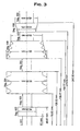
- Fig. 3 shows a workpiece with screw shell surface for production on a multi-axis machine tool according to the invention with 9 different segments.
- the machine control parameters according to the present invention will be exemplified below for the segment 8, a conical kneading element Seg. 8, where the virtual master axis is denoted by x: ⁇ B> Table. 1: ⁇ / b> Segment 008: 2.
Claims (38)
- Machine-outil (2) à plusieurs axes pour la fabrication de pièces dotées d'une surface d'enveloppe filetée, qui présente
un porte-pièce qui sert à reprendre une pièce,
un outil,
des axes mécaniques asservis destinés à l'usinage de la pièce ou au positionnement mutuel de la pièce et de l'outil, ainsi que
un dispositif de commande et/ou de régulation pour la commande des axes,
caractérisée en ce que
la commande de chaque axe mécanique par le dispositif de commande et/ou de régulation s'effectue au moyen d'une fonction ou relation sélectionnée librement, qui dépend de la valeur d'un axe virtuel paramétrable en tant qu'axe de référence pour les autres axes et également de la valeur d'autres paramètres, l'axe virtuel étant formé par le dispositif de commande et/ou de régulation au moyen d'une fonction ou relation qui dépend du temps et qui peut être sélectionnée librement. - Machine-outil (2) à plusieurs axes selon la revendication 1, caractérisée en ce que l'axe virtuel est formé par le dispositif de commande et/ou de régulation au moyen d'une fonction polynomiale.
- Machine-outil (2) à plusieurs axes selon la revendication 1, caractérisée en ce que l'axe virtuel est formé par le dispositif de commande et/ou de régulation au moyen d'une relation circulaire.
- Machine-outil (2) à plusieurs axes selon la revendication 1, caractérisée en ce que l'axe virtuel est formé par le dispositif de commande et/ou de régulation au moyen d'une relation donnée par un tableau de valeurs.
- Machine-outil (2) à plusieurs axes selon l'une des revendications 1 à 4, caractérisée en ce que la commande de chaque axe mécanique par le dispositif de commande et/ou de régulation s'effectue au moyen d'une fonction polynomiale qui dépend de la valeur de l'un des axes virtuels et des coefficients du polynôme.
- Machine-outil (2) à plusieurs axes selon l'une des revendications 1 à 4, caractérisée en ce que la commande de chaque axe mécanique par le dispositif de commande et/ou de régulation s'effectue au moyen d'une relation circulaire qui dépend de la valeur d'un des axes virtuels et de constantes d'un cercle, de préférence le rayon du cercle, son centre donné par une paire de coordonnées ou un sens de rotation.
- Machine-outil (2) à plusieurs axes selon l'une des revendications 1 à 4, caractérisée en ce que la commande de chaque axe mécanique par le dispositif de commande et/ou de régulation s'effectue au moyen d'une relation sélectionnée librement qui est fournie par un tableau de coordonnées.
- Machine-outil (2) à plusieurs axes selon la revendication 7, caractérisée en ce que l'on utilise comme coordonnées du tableau de coordonnées une coordonnée X, une coordonnée Y et un angle normal, de préférence vus en coupe frontale.
- Machine-outil (2) à plusieurs axes selon l'une des revendications 1 à 8, caractérisée en ce qu'au moins cinq axes mécaniques asservis sont prévus pour le positionnement mutuel entre la pièce et l'outil.
- Machine-outil (2) à plusieurs axes selon la revendication 9, caractérisée en ce que l'on utilise comme outil un disque de meulage et comme axes mécaniques au moins :un axe positionnable d'orientation radiale (χ) pour le disque de meulage,un chariot de meulage (ζ) qui peut être positionné à l'horizontale et perpendiculairement à l'axe d'orientation radiale pour le positionnement du disque de meulage dans la direction de déplacement du chariot de meulage,un axe positionnable de rotation (β) d'une tête de serrage qui permet de faire tourner la pièce dans le porte-pièce,un axe positionnable de pivotement (τ) pour l'inclinaison mutuelle de la pièce et du disque de meulage au moyen d'une rotation de l'axe du disque de meulage ou de sa projection parallèle dans le plan vertical (B) ainsi queun axe de rotation (ω) pour l'entraînement du disque de meulage.
- Machine-outil (2) à plusieurs axes selon la revendication 10, caractérisée en ce qu'elle prévoit également comme axe mécanique un axe positionnable de déplacement (δ) pour le contrôle de la position d'avancement du disque de meulage le long de l'axe du disque de meulage.
- Machine-outil (2) à plusieurs axes selon les revendications 10 ou 11, caractérisée en ce qu'elle prévoit également comme axe mécanique un axe de pivotement (σ) pour l'inclinaison mutuelle entre la pièce et le disque de meulage au moyen d'une rotation de l'axe du disque de meulage ou de sa projection parallèle dans le plan horizontal (A).
- Machine-outil (2) à plusieurs axes selon l'une des revendications 10 à 12, caractérisée en ce qu'elle prévoit également comme axe mécanique un axe de déplacement (η) pour le déplacement vertical mutuel entre la pièce et le disque de meulage.
- Machine-outil (2) à plusieurs axes selon l'une des revendications 10 à 13, caractérisée en ce qu'elle prévoit également comme axe mécanique un axe de pivotement (γ) pour l'inclinaison mutuelle entre la pièce et le disque de meulage au moyen d'une rotation de l'axe de la pièce ou de sa projection parallèle dans le plan horizontal (A).
- Machine-outil (2) à plusieurs axes selon l'une des revendications 1 à 14, caractérisée en ce qu'elle prévoit également une mémoire dans laquelle sont conservés des paramètres de commande de la machine auxquels le dispositif de commande et/ou de régulation peut accéder.
- Machine-outil (2) à plusieurs axes selon la revendication 15, caractérisée en ce qu'une structure de données qui permet de paramétrer un axe virtuel comme axe de référence pour d'autres axes est prévue dans la mémoire dans laquelle sont conservés les paramètres de commande de la machine auxquels le dispositif de commande et/ou de régulation peut accéder.
- Machine-outil (2) à plusieurs axes selon la revendication 16, caractérisée en ce qu'une structure de données qui permet également de paramétrer des axes mécaniques quelconques comme axes de référence pour d'autres axes est conservée dans la mémoire dans laquelle sont conservés les paramètres de commande de la machine auxquels le dispositif de commande et/ou de régulation peut accéder.
- Machine-outil (2) à plusieurs axes selon l'une des revendications 15 à 17, caractérisée en ce qu'une structure de données qui est prévue pour reprendre une définition de fonction ou de relation en vue de la formation de l'axe virtuel par le dispositif de commande et/ou de régulation est prévue dans la mémoire dans laquelle sont conservés les paramètres de commande de la machine auxquels le dispositif de commande et/ou de régulation peut accéder.
- Machine-outil (2) à plusieurs axes selon l'une des revendications 15 à 18, caractérisée en ce qu'une structure de données qui est prévue pour reprendre la définition d'une fonction ou d'une relation pour la commande des différents axes mécaniques par le dispositif de commande et/ou de régulation est prévue dans la mémoire dans laquelle sont conservés les paramètres de commande de la machine auxquels le dispositif de commande et/ou de régulation peut accéder.
- Machine-outil (2) à plusieurs axes selon la revendication 19, caractérisée en ce qu'elle prévoit au moins un type prédéfini de fonction ou de relation et en ce que la structure de données présente au moins un champ de données d'identification du type prédéfini de fonction ou de relation qui est utilisé pour la définition de la fonction de la relation de chaque axe mécanique.
- Machine-outil (2) à plusieurs axes selon la revendication 20, caractérisée en ce que comme type de fonction, elle prédéfinit une fonction polynomiale, de préférence du sixième degré, dont les paramètres sont les coefficients du polynôme.
- Machine-outil (2) à plusieurs axes selon les revendications 20 ou 21, caractérisée en ce que comme type de relation, elle prédéfinit une relation circulaire avec comme paramètres le rayon du cercle, le centre donné par une paire de coordonnées et un sens de rotation.
- Machine-outil (2) à plusieurs axes selon l'une des revendications 20 à 22, caractérisée en ce qu'elle prédéfinit comme type de relation un tableau de coordonnées dont les paramètres sont des coordonnées.
- Machine-outil (2) à plusieurs axes selon la revendication 23, caractérisée en ce qu'elle utilise comme coordonnées une coordonnée X, une coordonnée Y et un angle normal, de préférence vus en coupe frontale.
- Machine-outil (2) à plusieurs axes selon l'une des revendications 15 à 24, caractérisée en ce qu'une structure de données qui reprend une caractéristique du flanc de la pièce usinée par la commande de l'axe mécanique concerné par le dispositif de commande et/ou de régulation et de préférence une caractéristique d'un flanc droit ou d'un flanc gauche est prévue dans la mémoire dans laquelle sont conservés les paramètres de commande de la machine auxquels le dispositif de commande et/ou de régulation peut accéder.
- Machine-outil (2) à plusieurs axes selon l'une des revendications 15 à 24, caractérisée en ce qu'une structure de données qui rassemble au moins un groupe de paramètres de commande de machine qui correspond à une partie de la pièce, sous la forme d'un segment doté d'une identification commune de segment et de préférence d'un numéro de segment est prévue dans la mémoire dans laquelle sont conservés les paramètres de commande de la machine auxquels le dispositif de commande et/ou de régulation peut accéder.
- Machine-outil (2) à plusieurs axes selon la revendication 26, caractérisée en ce que dans un segment sont rassemblés toujours un groupe de paramètres de commande de machine qui paramètre le même axe comme axe de référence.
- Procédé de commande d'une machine-outil (2) à plusieurs axes selon l'une des revendications 1 à 27, dans lequel :un axe virtuel est d'abord paramétré comme axe de référence pour d'autres axes,et ensuite, pendant que la machine fonctionne pour usiner la pièce,les différents axes mécaniques sont commandés par le dispositif de commande et/ou de régulation au moyen d'une fonction ou relation sélectionnée librement qui dépend de la valeur de l'axe virtuel paramétré comme axe de référence pour d'autres axes, et formé par le dispositif de commande et/ou de régulation au moyen d'une fonction ou relation sélectionnée librement et dépendant du temps, et également de la valeur d'autres paramètres.
- Support de données ou signal électronique de support (3) qui contiennent des paramètres de commande de machine destinés à être lus dans une machine-outil (2) à plusieurs axes selon l'une des revendications 1 à 27, caractérisé en ce que
sur le support de données ou sur le signal électronique de support sont prévus :au moins une structure de données qui présente un champ de données qui permet la paramétrisation d'un axe virtuel comme axe de référence pour d'autres axes,au moins une structure de données qui est prévue pour reprendre la définition d'une fonction ou relation en vue de la formation de l'axe virtuel par le dispositif de commande et/ou de régulation etau moins une structure de données qui est prévue pour reprendre la définition d'une fonction ou d'une relation pour la commande de chaque axe mécanique par le dispositif de commande et/ou de régulation eten ce que le support de données ou le signal électronique de support (3) commandent la machine-outil (2) lors de la lecture ou après la lecture au moyen de cette structure de données, par le procédé selon la revendication 28. - Support de données ou signal électronique de support (3) qui contiennent des paramètres de commande de machine selon la revendication 29, destinés à être lus dans une machine-outil (2) à plusieurs axes selon l'une des revendications 1 à 27, caractérisés en ce que la structure de données présente au moins un champ de données destiné à l'identification d'au moins un type prédéfini de fonction ou de relation, de préférence un type de fonction polynomiale, un type de relation circulaire ou un type de tableau de coordonnées qui sont utilisés pour la définition de la fonction ou de la relation de chaque axe mécanique.
- Support de données ou signal électronique de support (3) qui contiennent des paramètres de commande de machine selon l'une des revendications 29 ou 30 destinés à être lus dans une machine-outil (2) à plusieurs axes selon l'une des revendications 1 à 27, caractérisés en ce qu'au moins une structure de données prévue pour reprendre une caractéristique du flanc de la pièce usinée par la commande de chaque axe mécanique par le dispositif de commande et/ou de régulation, de préférence une caractéristique d'un flanc droit ou d'un flanc gauche, est prévue sur le support de données ou sur le signal électronique de support.
- Support de données ou signal électronique de support (3) qui contiennent des paramètres de commande de machine selon l'une des revendications 29 à 31 destinés à être lus dans une machine-outil (2) à plusieurs axes selon l'une des revendications 1 à 27, caractérisés en ce qu'au moins une structure de données qui rassemble au moins un groupe de paramètres de commande de machine qui correspond à une partie de la pièce, comme segment sous une identification commune de segment, de préférence un numéro de segment, est prévue sur le support de données ou dans le signal électronique de support.
- Support de données ou signal électronique de support (3) qui contiennent des paramètres de commande de machine selon la revendication 32 destinés à être lus dans une machine-outil (2) à plusieurs axes selon l'une des revendications 1 à 27, caractérisés en ce que les mêmes groupes de paramètres de commande de machine sont toujours rassemblés en tant que segment dans lequel le même axe est paramétré comme axe de référence.
- Support de données ou signal électronique de support (3) qui contiennent des paramètres de commande de machine selon l'une des revendications 29 à 33 destinés à être lus dans une machine-outil (2) à plusieurs axes selon l'une des revendications 1 à 27, caractérisés en ce qu'au moins une structure de données qui permet également de paramétrer des axes mécaniques quelconques comme axe de référence pour d'autres axes est prévue sur le support de données ou sur le signal électronique de données.
- Machine-outil (2) à plusieurs axes selon l'une des revendications 1 à 27, caractérisée en ce qu'elle présente en outre des moyens pour lire dans la mémoire des paramètres de commande de machine pour le dispositif de commande et/ou de régulation qui proviennent d'un support de données ou d'un signal électronique de support (3) selon l'une des revendications 29 à 34.
- Procédé de formation de paramètres de commande de machine pour une machine-outil à plusieurs axes selon l'une des revendications 1 à 27 et 35, caractérisé en ce qu'il forme au moins un support de données ou un signal électronique de support (3) qui contiennent des paramètres de commande de machine selon l'une des revendications 29 à 34.
- Système informatique (1) destiné à former des paramètres de commande de machine pour une machine-outil (2) à plusieurs axes selon l'une des revendications 1 à 27 et 35, qui présente au moins une unité de traitement de données et au moins une mémoire, caractérisé en ce que l'unité de traitement de données est programmée de manière à former au moins un support de données ou un signal électronique de données (3) qui contiennent des paramètres de commande de machine selon l'une des revendications 29 à 34.
- Programme informatique qui présente des moyens de codage de programme en vue de mettre en oeuvre le procédé selon la revendication 36 lorsque le programme est exécuté sur un ordinateur.
Applications Claiming Priority (1)
| Application Number | Priority Date | Filing Date | Title |
|---|---|---|---|
| PCT/EP2003/011568 WO2005047995A1 (fr) | 2003-10-17 | 2003-10-17 | Systeme de commande informatique de donnees neutres pour une machine-outil servant a la fabrication de pieces usinees comportant une surface d'enveloppe filetee et machine-outil associee |
Publications (2)
| Publication Number | Publication Date |
|---|---|
| EP1556744A1 EP1556744A1 (fr) | 2005-07-27 |
| EP1556744B1 true EP1556744B1 (fr) | 2008-01-09 |
Family
ID=34585835
Family Applications (1)
| Application Number | Title | Priority Date | Filing Date |
|---|---|---|---|
| EP03785630A Expired - Lifetime EP1556744B1 (fr) | 2003-10-17 | 2003-10-17 | Systeme de commande informatique de donnees neutres pour une machine-outil servant a la fabrication de pieces usinees comportant une surface d'enveloppe filetee et machine-outil associee |
Country Status (12)
| Country | Link |
|---|---|
| US (2) | US7925372B2 (fr) |
| EP (1) | EP1556744B1 (fr) |
| JP (1) | JP4959982B2 (fr) |
| KR (1) | KR101261059B1 (fr) |
| CN (1) | CN100437406C (fr) |
| AT (1) | ATE383600T1 (fr) |
| AU (1) | AU2003294699A1 (fr) |
| CA (1) | CA2539360C (fr) |
| DE (1) | DE50308990D1 (fr) |
| ES (1) | ES2299744T3 (fr) |
| MX (1) | MXPA06003915A (fr) |
| WO (1) | WO2005047995A1 (fr) |
Families Citing this family (7)
| Publication number | Priority date | Publication date | Assignee | Title |
|---|---|---|---|---|
| CA2623961C (fr) | 2005-10-04 | 2013-08-06 | The Gleason Works | Fabrication de roues droites coniques |
| JP4841269B2 (ja) * | 2006-02-28 | 2011-12-21 | 株式会社ニデック | 眼鏡レンズ加工装置 |
| JP5401757B2 (ja) * | 2006-11-30 | 2014-01-29 | 株式会社ジェイテクト | 加工装置 |
| DE102010039491A1 (de) * | 2010-08-18 | 2012-02-23 | Deckel Maho Pfronten Gmbh | Verfahren und Vorrichtung zum Erzeugen von Steuerdaten zur Ausbildung einer Zahnflanke durch fräsende Bearbeitung eines Werkstücks an einer Werkzeugmaschine |
| US20120046777A1 (en) * | 2010-08-19 | 2012-02-23 | Imhoff Jamie L | Integrated machining and part inspection method |
| DE102010041489A1 (de) * | 2010-09-27 | 2012-03-29 | Deckel Maho Pfronten Gmbh | Verfahren zum Herstellen eines eine Pfeilverzahnung aufweisenden Zahnrads und Verfahren und Vorrichtung zum Erzeugen von Steuerdaten zur Ausbildung einer Pfeilverzahnung auf einem Werkstück |
| CN114643391B (zh) * | 2022-03-23 | 2023-07-07 | 广州数控设备有限公司 | 一种针对蜗杆进行铣削和磨削相结合的自动加工方法 |
Family Cites Families (44)
| Publication number | Priority date | Publication date | Assignee | Title |
|---|---|---|---|---|
| US4405829A (en) | 1977-12-14 | 1983-09-20 | Massachusetts Institute Of Technology | Cryptographic communications system and method |
| US4329096A (en) * | 1979-01-24 | 1982-05-11 | Power Engineering And Manufacturing, Ltd. | Gear cutter |
| JPS57111792A (en) | 1980-12-29 | 1982-07-12 | Fanuc Ltd | Program copying preventing system |
| JPS6127649U (ja) | 1984-07-26 | 1986-02-19 | 宣行 杉村 | Nc旋盤のねじ用タツチセンサ |
| US4672549A (en) | 1984-11-01 | 1987-06-09 | Saxton Richard E | Coil spring forming machine |
| JPS62150438A (ja) | 1985-12-24 | 1987-07-04 | Omron Tateisi Electronics Co | 制御機器のプログラムプロテクト装置 |
| GB8622941D0 (en) | 1986-09-24 | 1986-10-29 | Gen Electric Co Plc | Computer system |
| EP0709157B1 (fr) * | 1987-08-24 | 2001-11-07 | The Gleason Works | Machine à plusieurs axes pour le taillage des engrenages coniques et hypoides |
| DE3752009T3 (de) | 1987-08-24 | 2004-04-01 | The Gleason Works | Mehrfachachsenzahnradwälzmaschine zur herstellung von kegelrädern und hypoidrädern |
| AU664372B2 (en) * | 1991-06-04 | 1995-11-16 | Anca Pty Ltd | Improvements in or relating to computer numerically controlled machines |
| JP2658633B2 (ja) | 1991-07-10 | 1997-09-30 | 三菱電機株式会社 | 通信装置 |
| US5175962A (en) * | 1991-09-05 | 1993-01-05 | The Gleason Works | Method of and apparatus for machining spur and helical gears |
| JP2697399B2 (ja) * | 1991-09-13 | 1998-01-14 | 三菱電機株式会社 | 位置決め装置及びそのプログラム表示方法 |
| WO1994022655A1 (fr) * | 1993-04-05 | 1994-10-13 | Procontrol Ag | Machine de moulage par injection a entrainement electrique et son procede de guidage |
| JPH07129207A (ja) | 1993-10-28 | 1995-05-19 | Fanuc Ltd | 数値制御システム |
| DE4342648A1 (de) | 1993-12-14 | 1995-06-29 | Hermann J Prof Dr Stadtfeld | Verfahren zur kontrollierten Entwicklung von Kegelrädern und Vorrichtung zur Durchführung des Verfahrens |
| US5573449A (en) | 1994-03-16 | 1996-11-12 | The Gleason Works | Threaded grinding wheel, method of dressing, and grinding a workpiece therewith |
| US5580298A (en) * | 1994-09-27 | 1996-12-03 | The Gleason Works | Method of producing tooth flank surface modifications |
| US5892900A (en) | 1996-08-30 | 1999-04-06 | Intertrust Technologies Corp. | Systems and methods for secure transaction management and electronic rights protection |
| ATE211271T1 (de) | 1995-06-26 | 2002-01-15 | Siemens Ag | Numerisches steuerverfahren |
| DE19545083A1 (de) * | 1995-12-04 | 1997-06-05 | Grundig Emv | Verfahren zur Steuerung einer mehrachsigen Werkzeugmaschine |
| AUPO206596A0 (en) | 1996-08-30 | 1996-09-26 | Anca Pty Ltd | Tool grinding simulation system |
| US5844191A (en) | 1997-07-31 | 1998-12-01 | Westinghouse Electric Corporation | Method of and system for manufacturing a helical cutter |
| US5868051A (en) | 1997-08-28 | 1999-02-09 | Pakos Group | Method and apparatus for machining with a pivoting cutting tool |
| WO1999047300A1 (fr) | 1998-03-18 | 1999-09-23 | The Gleason Works | Meule filetee et procede de decrassage |
| JP3713141B2 (ja) | 1998-05-19 | 2005-11-02 | インターナショナル・ビジネス・マシーンズ・コーポレーション | プログラムの不正実行防止方法 |
| US6489741B1 (en) | 1998-08-25 | 2002-12-03 | Genmark Automation, Inc. | Robot motion compensation system |
| JP2000076063A (ja) | 1998-08-31 | 2000-03-14 | Open Loop:Kk | 認証システム、認証装置及び記録媒体 |
| US20010020228A1 (en) | 1999-07-09 | 2001-09-06 | International Business Machines Corporation | Umethod, system and program for managing relationships among entities to exchange encryption keys for use in providing access and authorization to resources |
| DE19935320A1 (de) | 1999-07-28 | 2001-02-08 | Schneider Automation Gmbh | Verfahren zur Überwachung eines Werkstückes während eines Transport- und/oder Fertigungsprozesses |
| DE10008973B4 (de) | 2000-02-25 | 2004-10-07 | Bayerische Motoren Werke Ag | Autorisierungsverfahren mit Zertifikat |
| DE10125383B4 (de) | 2000-12-15 | 2006-12-14 | Siemens Ag | Verschlüsselung von Steuerungsprogrammen |
| WO2002063824A1 (fr) | 2001-02-05 | 2002-08-15 | Dieter Otten | Protocole, systeme et dispositifs de telecommunication pour effectuer un vote electronique de maniere anonyme et authentique |
| US6687566B2 (en) | 2001-04-27 | 2004-02-03 | Okuma Corporation | Method of machining a female screw and dressing a grinding wheel for female screw machining |
| DE10124800A1 (de) | 2001-05-21 | 2002-12-12 | Siemens Ag | Prozessautomatisierungssystem und Prozessgerät für ein Prozessautomatisierungssystem |
| JP4770076B2 (ja) * | 2001-07-02 | 2011-09-07 | 三菱電機株式会社 | 数値制御装置 |
| ITVI20010149A1 (it) | 2001-07-04 | 2003-01-04 | Adriano Cazzavillan | Metodo per coordinare e sincronizzare il movimento di assi servo-assistiti |
| JP2003044109A (ja) * | 2001-07-27 | 2003-02-14 | Yaskawa Electric Corp | ワ−ク座標系設定手段を持つ多軸工作機械の数値制御装置 |
| GB2403441B (en) | 2001-09-17 | 2005-02-16 | Uni Screw Worldwide Inc | Method of manufacturing a cold forming punch |
| DE10149175A1 (de) * | 2001-10-04 | 2003-04-17 | Heidenhain Gmbh Dr Johannes | Verfahren zur Bahnsteuerung |
| JP4316850B2 (ja) | 2002-09-26 | 2009-08-19 | 森精機興産株式会社 | 複合加工工作機械における加工方法 |
| US7003373B2 (en) * | 2002-09-27 | 2006-02-21 | Siemens Aktiengesellschaft | Method and device for numerical control |
| DE10261592B3 (de) * | 2002-12-24 | 2004-10-28 | Reis Gmbh & Co. Maschinenfabrik | Knickarmroboter |
| US6985793B2 (en) | 2003-01-31 | 2006-01-10 | Delphi Technologies, Inc. | Horizontally structured CAD/CAM coordinate system for manufacturing design |
-
2003
- 2003-10-17 MX MXPA06003915A patent/MXPA06003915A/es active IP Right Grant
- 2003-10-17 AT AT03785630T patent/ATE383600T1/de active
- 2003-10-17 CN CNB2003801105458A patent/CN100437406C/zh not_active Expired - Fee Related
- 2003-10-17 KR KR1020067008886A patent/KR101261059B1/ko not_active IP Right Cessation
- 2003-10-17 ES ES03785630T patent/ES2299744T3/es not_active Expired - Lifetime
- 2003-10-17 US US10/575,532 patent/US7925372B2/en not_active Expired - Fee Related
- 2003-10-17 CA CA2539360A patent/CA2539360C/fr not_active Expired - Fee Related
- 2003-10-17 DE DE50308990T patent/DE50308990D1/de not_active Expired - Lifetime
- 2003-10-17 AU AU2003294699A patent/AU2003294699A1/en not_active Abandoned
- 2003-10-17 WO PCT/EP2003/011568 patent/WO2005047995A1/fr active IP Right Grant
- 2003-10-17 EP EP03785630A patent/EP1556744B1/fr not_active Expired - Lifetime
- 2003-10-17 JP JP2005510541A patent/JP4959982B2/ja not_active Expired - Fee Related
-
2006
- 2006-07-07 US US11/483,275 patent/US7983786B2/en not_active Expired - Fee Related
Also Published As
| Publication number | Publication date |
|---|---|
| JP4959982B2 (ja) | 2012-06-27 |
| US20060253218A1 (en) | 2006-11-09 |
| CN100437406C (zh) | 2008-11-26 |
| US7983786B2 (en) | 2011-07-19 |
| KR20060123135A (ko) | 2006-12-01 |
| CA2539360A1 (fr) | 2005-05-26 |
| JP2007515298A (ja) | 2007-06-14 |
| US20070112455A1 (en) | 2007-05-17 |
| US7925372B2 (en) | 2011-04-12 |
| WO2005047995A1 (fr) | 2005-05-26 |
| ATE383600T1 (de) | 2008-01-15 |
| AU2003294699A1 (en) | 2004-06-06 |
| ES2299744T3 (es) | 2008-06-01 |
| AU2003294699A8 (en) | 2005-06-06 |
| CN1860421A (zh) | 2006-11-08 |
| KR101261059B1 (ko) | 2013-05-06 |
| EP1556744A1 (fr) | 2005-07-27 |
| CA2539360C (fr) | 2013-11-26 |
| DE50308990D1 (de) | 2008-02-21 |
| MXPA06003915A (es) | 2006-07-05 |
Similar Documents
| Publication | Publication Date | Title |
|---|---|---|
| EP2946865B1 (fr) | Procédé de détermination de position de développantes pour des engrenages | |
| EP1981674B1 (fr) | Procede d'usinage de roues coniques dans un procede de division avec compensation complete des erreurs de division | |
| EP3546101B1 (fr) | Procédé et dispositif servant à tailler des roues d'usinage par décolletage en développante | |
| EP2923790B1 (fr) | Procédé de meulage de roues coniques dans un procédé de rectification en bout | |
| EP3724598B1 (fr) | Procédé et dispositif de mesure d'un outil pour l'usinage par génération | |
| DE2307493C3 (de) | Steuereinrichtung an einer Zahnflankenschleifmaschine zum Herstellen von Zahnflanken mit Korrektur in Breiten- und Höhenrichtung | |
| EP3061564A1 (fr) | Dispositif de fraisage pour la fabrication de verre de lunette comprenant deux stations de fraisage | |
| EP3147059B1 (fr) | Procede de fabrication d'une piece usinee presentant une geometrie de denture modifiee | |
| DE202017106229U1 (de) | Bearbeitungsvorrichtung | |
| EP3118699A2 (fr) | Procede de fabrication d'une piece dentee comprenant une geometrie de surface modifiee | |
| EP1556744B1 (fr) | Systeme de commande informatique de donnees neutres pour une machine-outil servant a la fabrication de pieces usinees comportant une surface d'enveloppe filetee et machine-outil associee | |
| EP3945381A1 (fr) | Fabrication de surfaces déterminables à l'aide des segments coniques au moyen d'une machine-outil | |
| EP0477398B1 (fr) | Procédé d'usinage de pièces avec une machine à commande numérique | |
| DE112016007167B4 (de) | Numerische Steuervorrichtung | |
| DE102012201732B4 (de) | Numerisch gesteuerte Werkzeugmaschine und Verfahren zum Steuern eines automatischen rotatorischen Ausrichtvorgangs eines Zahnrads an der Werkzeugmaschine | |
| DE3700887C2 (fr) | ||
| EP1796862A1 (fr) | Dispositif et procede pour usiner des roues dentees dans le cadre du procede de division, avec un temps de division reduit | |
| EP3139230A2 (fr) | Procede de fabrication d'une piece dentee comprenant une geometrie de surface modifiee | |
| DE102015008972A1 (de) | Verfahren zur Herstellung eines oder mehrerer Werkstücke | |
| DE3919301C2 (de) | Verfahren zum Schleifen eines Innengewindes eines Werkstücks | |
| EP2492766A1 (fr) | Procédé et dispositif de commande du mouvement d'un élément de machine d'une machine-outil pour la fabrication d'une roue dentée | |
| DE102019005405A1 (de) | Verfahren zum Hartfeinbearbeiten zweier Verzahnungen an einem Werkstück | |
| DE3908844A1 (de) | Numerische steuerung fuer werkzeugmaschinen oder roboter | |
| EP0563412A1 (fr) | Machine-outil à commande numérique avec interruption et reprise d'usinage | |
| DE102010026989B4 (de) | Verfahren und Vorrichtung zur spannenden Fertigung von Bogenverzahnungen an Kegelrädern |
Legal Events
| Date | Code | Title | Description |
|---|---|---|---|
| PUAI | Public reference made under article 153(3) epc to a published international application that has entered the european phase |
Free format text: ORIGINAL CODE: 0009012 |
|
| 17P | Request for examination filed |
Effective date: 20041102 |
|
| AK | Designated contracting states |
Kind code of ref document: A1 Designated state(s): AT BE BG CH CY CZ DE DK EE ES FI FR GB GR HU IE IT LI LU MC NL PT RO SE SI SK TR |
|
| AX | Request for extension of the european patent |
Extension state: AL LT LV MK |
|
| RIN1 | Information on inventor provided before grant (corrected) |
Inventor name: LONDON, WOLFGANG Inventor name: BLUMBERG, MANFRED Inventor name: DIRRICHS, STEFAN Inventor name: TOEPFER, GARY |
|
| 17Q | First examination report despatched |
Effective date: 20060330 |
|
| DAX | Request for extension of the european patent (deleted) | ||
| GRAP | Despatch of communication of intention to grant a patent |
Free format text: ORIGINAL CODE: EPIDOSNIGR1 |
|
| GRAS | Grant fee paid |
Free format text: ORIGINAL CODE: EPIDOSNIGR3 |
|
| GRAA | (expected) grant |
Free format text: ORIGINAL CODE: 0009210 |
|
| AK | Designated contracting states |
Kind code of ref document: B1 Designated state(s): AT BE BG CH CY CZ DE DK EE ES FI FR GB GR HU IE IT LI LU MC NL PT RO SE SI SK TR |
|
| REG | Reference to a national code |
Ref country code: GB Ref legal event code: FG4D Free format text: NOT ENGLISH |
|
| REG | Reference to a national code |
Ref country code: CH Ref legal event code: EP |
|
| REG | Reference to a national code |
Ref country code: IE Ref legal event code: FG4D Free format text: LANGUAGE OF EP DOCUMENT: GERMAN |
|
| REF | Corresponds to: |
Ref document number: 50308990 Country of ref document: DE Date of ref document: 20080221 Kind code of ref document: P |
|
| REG | Reference to a national code |
Ref country code: SE Ref legal event code: TRGR |
|
| REG | Reference to a national code |
Ref country code: CH Ref legal event code: NV Representative=s name: SUSI PRYDE-HAENI BSC |
|
| GBT | Gb: translation of ep patent filed (gb section 77(6)(a)/1977) |
Effective date: 20080414 |
|
| PG25 | Lapsed in a contracting state [announced via postgrant information from national office to epo] |
Ref country code: SI Free format text: LAPSE BECAUSE OF FAILURE TO SUBMIT A TRANSLATION OF THE DESCRIPTION OR TO PAY THE FEE WITHIN THE PRESCRIBED TIME-LIMIT Effective date: 20080109 |
|
| REG | Reference to a national code |
Ref country code: ES Ref legal event code: FG2A Ref document number: 2299744 Country of ref document: ES Kind code of ref document: T3 |
|
| PG25 | Lapsed in a contracting state [announced via postgrant information from national office to epo] |
Ref country code: BG Free format text: LAPSE BECAUSE OF FAILURE TO SUBMIT A TRANSLATION OF THE DESCRIPTION OR TO PAY THE FEE WITHIN THE PRESCRIBED TIME-LIMIT Effective date: 20080409 |
|
| ET | Fr: translation filed | ||
| PG25 | Lapsed in a contracting state [announced via postgrant information from national office to epo] |
Ref country code: PT Free format text: LAPSE BECAUSE OF FAILURE TO SUBMIT A TRANSLATION OF THE DESCRIPTION OR TO PAY THE FEE WITHIN THE PRESCRIBED TIME-LIMIT Effective date: 20080609 |
|
| REG | Reference to a national code |
Ref country code: IE Ref legal event code: FD4D |
|
| PG25 | Lapsed in a contracting state [announced via postgrant information from national office to epo] |
Ref country code: IE Free format text: LAPSE BECAUSE OF FAILURE TO SUBMIT A TRANSLATION OF THE DESCRIPTION OR TO PAY THE FEE WITHIN THE PRESCRIBED TIME-LIMIT Effective date: 20080109 Ref country code: CZ Free format text: LAPSE BECAUSE OF FAILURE TO SUBMIT A TRANSLATION OF THE DESCRIPTION OR TO PAY THE FEE WITHIN THE PRESCRIBED TIME-LIMIT Effective date: 20080109 Ref country code: DK Free format text: LAPSE BECAUSE OF FAILURE TO SUBMIT A TRANSLATION OF THE DESCRIPTION OR TO PAY THE FEE WITHIN THE PRESCRIBED TIME-LIMIT Effective date: 20080109 Ref country code: SK Free format text: LAPSE BECAUSE OF FAILURE TO SUBMIT A TRANSLATION OF THE DESCRIPTION OR TO PAY THE FEE WITHIN THE PRESCRIBED TIME-LIMIT Effective date: 20080109 |
|
| PLBE | No opposition filed within time limit |
Free format text: ORIGINAL CODE: 0009261 |
|
| STAA | Information on the status of an ep patent application or granted ep patent |
Free format text: STATUS: NO OPPOSITION FILED WITHIN TIME LIMIT |
|
| PG25 | Lapsed in a contracting state [announced via postgrant information from national office to epo] |
Ref country code: RO Free format text: LAPSE BECAUSE OF FAILURE TO SUBMIT A TRANSLATION OF THE DESCRIPTION OR TO PAY THE FEE WITHIN THE PRESCRIBED TIME-LIMIT Effective date: 20080109 |
|
| 26N | No opposition filed |
Effective date: 20081010 |
|
| PG25 | Lapsed in a contracting state [announced via postgrant information from national office to epo] |
Ref country code: EE Free format text: LAPSE BECAUSE OF FAILURE TO SUBMIT A TRANSLATION OF THE DESCRIPTION OR TO PAY THE FEE WITHIN THE PRESCRIBED TIME-LIMIT Effective date: 20080109 |
|
| PG25 | Lapsed in a contracting state [announced via postgrant information from national office to epo] |
Ref country code: MC Free format text: LAPSE BECAUSE OF NON-PAYMENT OF DUE FEES Effective date: 20081031 |
|
| PG25 | Lapsed in a contracting state [announced via postgrant information from national office to epo] |
Ref country code: CY Free format text: LAPSE BECAUSE OF FAILURE TO SUBMIT A TRANSLATION OF THE DESCRIPTION OR TO PAY THE FEE WITHIN THE PRESCRIBED TIME-LIMIT Effective date: 20080109 |
|
| PG25 | Lapsed in a contracting state [announced via postgrant information from national office to epo] |
Ref country code: LU Free format text: LAPSE BECAUSE OF NON-PAYMENT OF DUE FEES Effective date: 20081017 Ref country code: HU Free format text: LAPSE BECAUSE OF FAILURE TO SUBMIT A TRANSLATION OF THE DESCRIPTION OR TO PAY THE FEE WITHIN THE PRESCRIBED TIME-LIMIT Effective date: 20080710 |
|
| PG25 | Lapsed in a contracting state [announced via postgrant information from national office to epo] |
Ref country code: TR Free format text: LAPSE BECAUSE OF FAILURE TO SUBMIT A TRANSLATION OF THE DESCRIPTION OR TO PAY THE FEE WITHIN THE PRESCRIBED TIME-LIMIT Effective date: 20080109 |
|
| PG25 | Lapsed in a contracting state [announced via postgrant information from national office to epo] |
Ref country code: GR Free format text: LAPSE BECAUSE OF FAILURE TO SUBMIT A TRANSLATION OF THE DESCRIPTION OR TO PAY THE FEE WITHIN THE PRESCRIBED TIME-LIMIT Effective date: 20080410 |
|
| REG | Reference to a national code |
Ref country code: DE Ref legal event code: R082 Ref document number: 50308990 Country of ref document: DE Representative=s name: KIANI & SPRINGORUM PATENT- U. RECHTSANWAELTE, DE |
|
| REG | Reference to a national code |
Ref country code: DE Ref legal event code: R081 Ref document number: 50308990 Country of ref document: DE Owner name: KLINGELNBERG GMBH, DE Free format text: FORMER OWNER: TRINARY ANLAGENBAU GMBH, 41063 MOENCHENGLADBACH, DE Effective date: 20140811 Ref country code: DE Ref legal event code: R082 Ref document number: 50308990 Country of ref document: DE Representative=s name: KIANI & SPRINGORUM PATENT- U. RECHTSANWAELTE, DE Effective date: 20140811 Ref country code: DE Ref legal event code: R082 Ref document number: 50308990 Country of ref document: DE Representative=s name: KIANI & SPRINGORUM PATENT- UND RECHTSANWAELTE, DE Effective date: 20140811 |
|
| REG | Reference to a national code |
Ref country code: GB Ref legal event code: 732E Free format text: REGISTERED BETWEEN 20140911 AND 20140917 |
|
| REG | Reference to a national code |
Ref country code: CH Ref legal event code: PUE Owner name: KLINGELNBERG GMBH, DE Free format text: FORMER OWNER: TRINARY ANLAGENBAU GMBH, DE |
|
| REG | Reference to a national code |
Ref country code: ES Ref legal event code: PC2A Owner name: KLINGELNBERG GMBH Effective date: 20150213 |
|
| REG | Reference to a national code |
Ref country code: FR Ref legal event code: TP Owner name: KLINGELNBERG GMBH, DE Effective date: 20150128 |
|
| REG | Reference to a national code |
Ref country code: NL Ref legal event code: SD Effective date: 20150617 |
|
| REG | Reference to a national code |
Ref country code: AT Ref legal event code: PC Ref document number: 383600 Country of ref document: AT Kind code of ref document: T Owner name: KLINGELNBERG GMBH, DE Effective date: 20150602 |
|
| REG | Reference to a national code |
Ref country code: FR Ref legal event code: PLFP Year of fee payment: 13 |
|
| REG | Reference to a national code |
Ref country code: FR Ref legal event code: PLFP Year of fee payment: 14 |
|
| REG | Reference to a national code |
Ref country code: FR Ref legal event code: PLFP Year of fee payment: 15 |
|
| PGFP | Annual fee paid to national office [announced via postgrant information from national office to epo] |
Ref country code: FI Payment date: 20171020 Year of fee payment: 15 Ref country code: DE Payment date: 20171019 Year of fee payment: 15 Ref country code: FR Payment date: 20171024 Year of fee payment: 15 |
|
| PGFP | Annual fee paid to national office [announced via postgrant information from national office to epo] |
Ref country code: BE Payment date: 20171019 Year of fee payment: 15 Ref country code: AT Payment date: 20171020 Year of fee payment: 15 Ref country code: GB Payment date: 20171019 Year of fee payment: 15 Ref country code: CH Payment date: 20171019 Year of fee payment: 15 Ref country code: SE Payment date: 20171019 Year of fee payment: 15 Ref country code: NL Payment date: 20171019 Year of fee payment: 15 Ref country code: IT Payment date: 20171023 Year of fee payment: 15 Ref country code: ES Payment date: 20171121 Year of fee payment: 15 |
|
| REG | Reference to a national code |
Ref country code: DE Ref legal event code: R119 Ref document number: 50308990 Country of ref document: DE |
|
| REG | Reference to a national code |
Ref country code: SE Ref legal event code: EUG |
|
| REG | Reference to a national code |
Ref country code: CH Ref legal event code: PL |
|
| REG | Reference to a national code |
Ref country code: NL Ref legal event code: MM Effective date: 20181101 |
|
| REG | Reference to a national code |
Ref country code: AT Ref legal event code: MM01 Ref document number: 383600 Country of ref document: AT Kind code of ref document: T Effective date: 20181017 |
|
| GBPC | Gb: european patent ceased through non-payment of renewal fee |
Effective date: 20181017 |
|
| REG | Reference to a national code |
Ref country code: BE Ref legal event code: MM Effective date: 20181031 Ref country code: BE Ref legal event code: PD Owner name: KLINGELNBERG GMBH; DE Free format text: DETAILS ASSIGNMENT: CHANGE OF OWNER(S), AFFECTATION / CESSION; FORMER OWNER NAME: TRINARY ANLAGENBAU GMBH Effective date: 20150112 |
|
| PG25 | Lapsed in a contracting state [announced via postgrant information from national office to epo] |
Ref country code: SE Free format text: LAPSE BECAUSE OF NON-PAYMENT OF DUE FEES Effective date: 20181018 Ref country code: DE Free format text: LAPSE BECAUSE OF NON-PAYMENT OF DUE FEES Effective date: 20190501 Ref country code: FI Free format text: LAPSE BECAUSE OF NON-PAYMENT OF DUE FEES Effective date: 20181017 Ref country code: NL Free format text: LAPSE BECAUSE OF NON-PAYMENT OF DUE FEES Effective date: 20181101 |
|
| PG25 | Lapsed in a contracting state [announced via postgrant information from national office to epo] |
Ref country code: BE Free format text: LAPSE BECAUSE OF NON-PAYMENT OF DUE FEES Effective date: 20181031 Ref country code: FR Free format text: LAPSE BECAUSE OF NON-PAYMENT OF DUE FEES Effective date: 20181031 Ref country code: CH Free format text: LAPSE BECAUSE OF NON-PAYMENT OF DUE FEES Effective date: 20181031 Ref country code: LI Free format text: LAPSE BECAUSE OF NON-PAYMENT OF DUE FEES Effective date: 20181031 |
|
| PG25 | Lapsed in a contracting state [announced via postgrant information from national office to epo] |
Ref country code: IT Free format text: LAPSE BECAUSE OF NON-PAYMENT OF DUE FEES Effective date: 20181017 Ref country code: AT Free format text: LAPSE BECAUSE OF NON-PAYMENT OF DUE FEES Effective date: 20181017 Ref country code: GB Free format text: LAPSE BECAUSE OF NON-PAYMENT OF DUE FEES Effective date: 20181017 |
|
| REG | Reference to a national code |
Ref country code: ES Ref legal event code: FD2A Effective date: 20191202 |
|
| PG25 | Lapsed in a contracting state [announced via postgrant information from national office to epo] |
Ref country code: ES Free format text: LAPSE BECAUSE OF NON-PAYMENT OF DUE FEES Effective date: 20181018 |