EP1556744B1 - Neutral data computer control system for a machine tool used to produce workpieces with a threaded surface and associated machine tool - Google Patents
Neutral data computer control system for a machine tool used to produce workpieces with a threaded surface and associated machine tool Download PDFInfo
- Publication number
- EP1556744B1 EP1556744B1 EP03785630A EP03785630A EP1556744B1 EP 1556744 B1 EP1556744 B1 EP 1556744B1 EP 03785630 A EP03785630 A EP 03785630A EP 03785630 A EP03785630 A EP 03785630A EP 1556744 B1 EP1556744 B1 EP 1556744B1
- Authority
- EP
- European Patent Office
- Prior art keywords
- axis
- machine tool
- loop
- relation
- closed
- Prior art date
- Legal status (The legal status is an assumption and is not a legal conclusion. Google has not performed a legal analysis and makes no representation as to the accuracy of the status listed.)
- Expired - Lifetime
Links
- 230000007935 neutral effect Effects 0.000 title abstract description 8
- 238000004590 computer program Methods 0.000 claims abstract description 15
- 238000012545 processing Methods 0.000 claims abstract description 9
- 238000000227 grinding Methods 0.000 claims description 55
- 230000006870 function Effects 0.000 claims description 43
- 238000000034 method Methods 0.000 claims description 15
- 230000001419 dependent effect Effects 0.000 claims description 13
- 238000006073 displacement reaction Methods 0.000 claims description 9
- 230000015572 biosynthetic process Effects 0.000 claims description 7
- 238000003754 machining Methods 0.000 claims description 3
- 230000036961 partial effect Effects 0.000 claims description 3
- 230000004913 activation Effects 0.000 claims 8
- 230000003213 activating effect Effects 0.000 claims 2
- 238000012544 monitoring process Methods 0.000 claims 1
- 238000004519 manufacturing process Methods 0.000 description 17
- 230000033001 locomotion Effects 0.000 description 12
- 230000001105 regulatory effect Effects 0.000 description 10
- 230000001276 controlling effect Effects 0.000 description 6
- 230000008859 change Effects 0.000 description 5
- 238000005096 rolling process Methods 0.000 description 5
- 230000008569 process Effects 0.000 description 3
- 238000005520 cutting process Methods 0.000 description 2
- 238000013461 design Methods 0.000 description 2
- 238000004898 kneading Methods 0.000 description 2
- 238000003801 milling Methods 0.000 description 2
- 230000006978 adaptation Effects 0.000 description 1
- 238000013459 approach Methods 0.000 description 1
- 230000001143 conditioned effect Effects 0.000 description 1
- 238000013499 data model Methods 0.000 description 1
- 238000013500 data storage Methods 0.000 description 1
- 230000000694 effects Effects 0.000 description 1
- 238000012986 modification Methods 0.000 description 1
- 230000004048 modification Effects 0.000 description 1
- 230000000717 retained effect Effects 0.000 description 1
- 230000011218 segmentation Effects 0.000 description 1
- 210000002023 somite Anatomy 0.000 description 1
- 230000036962 time dependent Effects 0.000 description 1
Images


Classifications
-
- B—PERFORMING OPERATIONS; TRANSPORTING
- B23—MACHINE TOOLS; METAL-WORKING NOT OTHERWISE PROVIDED FOR
- B23Q—DETAILS, COMPONENTS, OR ACCESSORIES FOR MACHINE TOOLS, e.g. ARRANGEMENTS FOR COPYING OR CONTROLLING; MACHINE TOOLS IN GENERAL CHARACTERISED BY THE CONSTRUCTION OF PARTICULAR DETAILS OR COMPONENTS; COMBINATIONS OR ASSOCIATIONS OF METAL-WORKING MACHINES, NOT DIRECTED TO A PARTICULAR RESULT
- B23Q15/00—Automatic control or regulation of feed movement, cutting velocity or position of tool or work
- B23Q15/007—Automatic control or regulation of feed movement, cutting velocity or position of tool or work while the tool acts upon the workpiece
-
- G—PHYSICS
- G05—CONTROLLING; REGULATING
- G05B—CONTROL OR REGULATING SYSTEMS IN GENERAL; FUNCTIONAL ELEMENTS OF SUCH SYSTEMS; MONITORING OR TESTING ARRANGEMENTS FOR SUCH SYSTEMS OR ELEMENTS
- G05B19/00—Programme-control systems
- G05B19/02—Programme-control systems electric
- G05B19/18—Numerical control [NC], i.e. automatically operating machines, in particular machine tools, e.g. in a manufacturing environment, so as to execute positioning, movement or co-ordinated operations by means of programme data in numerical form
- G05B19/414—Structure of the control system, e.g. common controller or multiprocessor systems, interface to servo, programmable interface controller
- G05B19/4142—Structure of the control system, e.g. common controller or multiprocessor systems, interface to servo, programmable interface controller characterised by the use of a microprocessor
-
- B—PERFORMING OPERATIONS; TRANSPORTING
- B23—MACHINE TOOLS; METAL-WORKING NOT OTHERWISE PROVIDED FOR
- B23Q—DETAILS, COMPONENTS, OR ACCESSORIES FOR MACHINE TOOLS, e.g. ARRANGEMENTS FOR COPYING OR CONTROLLING; MACHINE TOOLS IN GENERAL CHARACTERISED BY THE CONSTRUCTION OF PARTICULAR DETAILS OR COMPONENTS; COMBINATIONS OR ASSOCIATIONS OF METAL-WORKING MACHINES, NOT DIRECTED TO A PARTICULAR RESULT
- B23Q17/00—Arrangements for observing, indicating or measuring on machine tools
- B23Q17/22—Arrangements for observing, indicating or measuring on machine tools for indicating or measuring existing or desired position of tool or work
-
- G—PHYSICS
- G05—CONTROLLING; REGULATING
- G05B—CONTROL OR REGULATING SYSTEMS IN GENERAL; FUNCTIONAL ELEMENTS OF SUCH SYSTEMS; MONITORING OR TESTING ARRANGEMENTS FOR SUCH SYSTEMS OR ELEMENTS
- G05B19/00—Programme-control systems
- G05B19/02—Programme-control systems electric
- G05B19/18—Numerical control [NC], i.e. automatically operating machines, in particular machine tools, e.g. in a manufacturing environment, so as to execute positioning, movement or co-ordinated operations by means of programme data in numerical form
- G05B19/414—Structure of the control system, e.g. common controller or multiprocessor systems, interface to servo, programmable interface controller
-
- G—PHYSICS
- G05—CONTROLLING; REGULATING
- G05B—CONTROL OR REGULATING SYSTEMS IN GENERAL; FUNCTIONAL ELEMENTS OF SUCH SYSTEMS; MONITORING OR TESTING ARRANGEMENTS FOR SUCH SYSTEMS OR ELEMENTS
- G05B19/00—Programme-control systems
- G05B19/02—Programme-control systems electric
- G05B19/18—Numerical control [NC], i.e. automatically operating machines, in particular machine tools, e.g. in a manufacturing environment, so as to execute positioning, movement or co-ordinated operations by means of programme data in numerical form
- G05B19/4155—Numerical control [NC], i.e. automatically operating machines, in particular machine tools, e.g. in a manufacturing environment, so as to execute positioning, movement or co-ordinated operations by means of programme data in numerical form characterised by programme execution, i.e. part programme or machine function execution, e.g. selection of a programme
-
- G—PHYSICS
- G05—CONTROLLING; REGULATING
- G05B—CONTROL OR REGULATING SYSTEMS IN GENERAL; FUNCTIONAL ELEMENTS OF SUCH SYSTEMS; MONITORING OR TESTING ARRANGEMENTS FOR SUCH SYSTEMS OR ELEMENTS
- G05B2219/00—Program-control systems
- G05B2219/30—Nc systems
- G05B2219/50—Machine tool, machine tool null till machine tool work handling
- G05B2219/50229—Synchronize axis by simulating several virtual axis to control real axis
Definitions
- the present invention relates to a neutral data computer control system for a machine tool having a computer system, computer program and computer program products, and an associated machine tool.
- Multi-axis positioning systems as they also machine tools require, the synchronization of the individual movements with each other, so that a defined curve is traversed in three-dimensional space. This is achieved in that one of the axes not only their own positioning, but also serves as a guide or guide axis of the synchronization of the other axes to be positioned.
- the coefficients a 0 , a 1 , a 2 a 3 and a 4 serve as further parameters of the position control of the respective axis controlled by the function f ( ⁇ ).
- leading axis used in the prior art is always one of the controllable mechanical axes of the machine tool.
- bevel gear cutting machines which work according to the rolling process and therefore, as in the case of EP 0 784 525 Having a cradle is usually this always necessary cradle as a leading axis, so therefore their rolling motion used as a guide movement for the synchronization of the other axis movements. In this way exists - also independent of the further concrete
- the rolling process can be used uniformly as a leading axis.
- a non-existent positionable pivot axis for pivoting workpiece and tool against each other by means of a rotation of the tool axis in the vertical by a pivot axis for pivoting workpiece and tool against each other by means of a rotation of the workpiece axis in the horizontal to be replaced without the machine control parameters a radial delivery axis or a positionable axis of rotation of a clamping head for rotation of the workpiece in the workpiece holder would be affected.
- the formation of the axial positions for the control of the mechanical axes can thus be kept completely independent of any actual movement of each axis of the machine tool, thus making it possible, when changing the machine to be controlled - within the geometrically possible - to recreate only the machine control parameters that are used to control axes that are additionally present on the new machine.
- the machine control parameters for axes that are encountered before and after the change of the machine can be maintained. In the case of the above-mentioned polynomials, this means, for example, that the coefficients a i, j defining the trajectory need not be newly formed for these axes.
- the virtual axis in the sense of the present invention does not serve its own control of mechanical Axes, in particular no software synthesis additional, in the mechanical reality of the machine tool to be controlled no equivalent finding axes, but only the synchronization of the control of other axes.
- a virtual axis is parameterized as a leading axis for other axes, and then during operation of the machine for machining the workpiece, the respective mechanical axes by the control and / or regulating device be controlled by a freely selectable function or relation, which of the value of the parameterized as a leading axis for other axes, formed by the control and / or regulating device by means of a dependent on the time arbitrary function or relation, virtual axis and also the value of other parameters depends so as to achieve with the aid of the virtual master axis, the synchronization of the axis positions with each other.
- the multiaxial machine tool according to the invention preferably has at least five controllable mechanical axes for positioning the workpiece and the tool in relation to one another, which enables the production of rotationally symmetrical workpieces. If one also wants to manufacture non-rotationally symmetrical workpieces, such as screws, then at least one additional axis, which is provided for pivoting the workpiece and the grinding disk against each other in the horizontal, as will be seen.
- a positionable displacement axis also denoted by ⁇ , be provided for controlling a feed position of the grinding wheel along the grinding wheel axis.
- the multi-axis machine tool according to the invention also has a pivot axis, also denoted by ⁇ , as a mechanical axis for pivoting workpiece and grinding wheel against each other by means of a rotation of the grinding wheel axis or its parallel projection in the horizontal plane, also labeled A, on, which also already mentioned Production of non-rotationally symmetrical workpieces allowed.
- a pivot axis also denoted by ⁇
- ⁇ a mechanical axis for pivoting workpiece and grinding wheel against each other by means of a rotation of the grinding wheel axis or its parallel projection in the horizontal plane, also labeled A, on, which also already mentioned Production of non-rotationally symmetrical workpieces allowed.
- this can also be achieved by a mechanical pivot axis, also denoted by ⁇ , for pivoting workpiece and grinding wheel against each other by means of a rotation of the workpiece axis or its parallel projection in the horizontal plane, also designated A.
- ⁇ a mechanical axis and a displacement axis, also referred to with ⁇ , be provided, which serves the vertical displacement of the workpiece and grinding wheel, against each other.
- the virtual axis itself is formed by the control and / or regulating device by means of a freely selectable function or relation, which depends on the time.
- the virtual axis is formed according to the present invention by means of a freely selectable function or relation, this can be done so that this virtual master axis is good over the entire manufacturing process without Leitachs Pizza, since in this way any conditional on the manufacturing process dependence of the leading axis due to their complete freedom of choice can be avoided.
- the present invention is advantageously also in the case of the operation of only one candidate type of machine, since in this case when using the optional virtual axis according to the invention no Leitachs monotone of the kind described occur more and thus no errors occurring as a result more on the workpieces come to light. If, on the other hand, the virtual master axis is selected, process-related dependencies may not be ruled out, which may then lead to the numerically unfavorably conditioned systems already mentioned.
- a freely selectable function comes in particular, as already in o.a. Example set forth, a polynomial function, but for example, a circle relation in question. Also, a freely selectable relation can also be defined by a value table.
- the control of the respective mechanical axis by the control and / or regulating device takes place by means of a freely selectable function or relation whereby the respective mechanical axis, as already stated at the outset, depends on the value of a virtually formed axis acting as a guide axis to achieve the synchronization of the axis positions with each other.
- the respective axis is also made dependent on the value of further parameters for controlling the desired position values.
- a polynomial function which is also dependent on the value of one of the virtual axes and polynomial coefficients can serve as a freely selectable function.
- a circle relation which is the value of one of the virtual axes and circle constants, preferably a circle radius and a given by a coordinate pair center and a direction of rotation.
- a relation formed by a coordinate table it is preferably formed by an X-coordinate, a Y-coordinate and a normal angle, preferably viewed in the frontal section.
- the multi-axis machine tool is characterized in that a memory is also provided, are stored in the machine control parameters, which is accessed by the control and / or regulating device, which is a flexible realization of the present invention a computer control allows.
- a data structure can be provided which allows the parameterization of the virtual axis as a leading axis for other axes, whereby it is also possible that there is a data structure that also allows the parameterization of any mechanical axis as a leading axis for other axes, such in order to be able to use older machine control parameters that have not yet been matched to the computer control system according to the invention.
- the function or relationship definition for the formation of the virtual axis as well as the function or relationship definition for the control of the respective mechanical axis by the control and / or regulating device can be flexibly stored in the memory.
- data fields can be used to identify predefined function or relation types, which are used for the function or relation definition of the respective mechanical axis.
- predefined function types are preferably about a polynomial function, about sixth degree, with polynomial coefficients as parameters or in turn a circle relation with circle radius and given by a coordinate pair center and a direction of rotation as parameters in question.
- a coordinate table with coordinates can also be predefined as a relation type; wherein preferably an X-coordinate, a Y-coordinate and a normal angle, preferably in the cross-sectional view, are used as coordinates.
- a multi-axis machine tool in the memory, in which machine control parameters are stored, which is accessed by the control and / or regulating device, there is a data structure for receiving an identification by the drive the respective mechanical axis by the control and / or regulating device machined workpiece edge, preferably a label for a right or a left flank, is provided.
- This parameter is required by the machine in the case of non-symmetrical grinding wheels, such as for making screws, to drive the respective flank with the correct side of the tool.
- this control parameter enables a force control or regulation corresponding to the respective edge.
- the memory storing machine control parameters accessed by the controller, there is also a data structure comprising at least one group of machine control parameters corresponding to a portion of the workpiece as a segment under a common segment identification , preferably a segment number, preferably always such a group of machine control parameters are combined as a segment, in which the same axis is parameterized as a leading axis.
- the structuring of the machine control parameters into segments makes it possible to map a segmentation of the workpiece given in reality also in the structuring of the machine control parameters, which improves their clarity and thus also the possibility of their assignment to workpiece cuts.
- Machine tools with a memory thus serve to represent machine control parameters in this memory, which trigger machine functions for workpiece production during operation of the machine. This can be done not only by a deposit in the memory of the machine, but also by reading a provided with appropriate machine control parameters disk, such as a floppy disk, a CD or a DVD or by reading an electronic carrier signal with these machine control parameters in the Multi-axis machine tool according to the invention, for example via a data line, as it is preferably also used in a data network.
- a data carrier or such a data carrier signal is constructed in accordance with the present invention for reading the data constructed as described above according to the invention into the multi-axis machine tool according to the invention for controlling it in accordance with the present invention.
- such a data carrier or such an electronic carrier signal according to claim 29, according to the invention parameterized with machine control parameters for reading in a multi-axis machine tool, wherein the data carrier or the electronic carrier signal, the machine tool by means of this data structure in the reading or after reading o.a. activates inventive method.
- the implementation of the present invention is a method for generating machine control parameters for a multi-axis machine tool, which according to the invention characterized in that it generates a data carrier or an electronic carrier signal with machine control parameters as shown above.
- this method can also be implemented on a computer system having at least one data processing unit and at least one memory, usually as a computer program, for example, having the corresponding instructions which are set up to carry out the method.
- a computer program can be present in any form, but in particular as a computer program product on a computer-readable medium, such as floppy disk, CD or DVD, wherein it has computer program code means, in each case after loading the computer program, a computer through the program for Implementation of the method according to the invention is caused.
- it can also be present, for example, as a computer program product which has a computer program on an electronic carrier signal in which, after the computer program has been loaded, a computer is caused by the program for carrying out the method according to the invention.
- the first machine 2 (in addition to other axes) has a mechanical pivot axis ⁇ for pivoting workpiece and grinding wheel against each other by means of a rotation of the grinding wheel axis or its parallel projection in the horizontal plane A; a possibility that the second machine 2a is missing.
- this has a pivot axis ⁇ for pivoting workpiece and grinding wheel against each other by means of a rotation of the workpiece axis or its parallel projection in the horizontal plane A.
- the computer system 1 for the first inventive machine 2 are also used for the second inventive machine tool 2a when the generated machine control parameters make use of a virtual master axis according to the present invention.
- Both machines 2, 2a have a virtual leading axis, so that only the machine control parameters for the pivot axis ⁇ instead of the pivot axis ⁇ must be formed in a machine change from the first machine 2 to the second machine 2a. All other machine control parameters, on the other hand, can be retained since they are coupled via the virtual master axis.
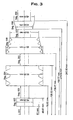
- Fig. 3 shows a workpiece with screw shell surface for production on a multi-axis machine tool according to the invention with 9 different segments.
- the machine control parameters according to the present invention will be exemplified below for the segment 8, a conical kneading element Seg. 8, where the virtual master axis is denoted by x: ⁇ B> Table. 1: ⁇ / b> Segment 008: 2.
Abstract
Description
Die vorliegende Erfindung betrifft ein Neutraldaten-Computersteuerungssystem für eine Werkzeugmaschine mit Computersystem, Computerprogramm und Computerprogrammprodukten, sowie einer zugehörigen Werkzeugmaschine.The present invention relates to a neutral data computer control system for a machine tool having a computer system, computer program and computer program products, and an associated machine tool.
Bei der Fertigung von Werkzeugmaschinen tritt heutzutage vor dem Hintergrund mehr und mehr vernetzter Fertigungsprozesse und deren Standardisierung in der Industrie das Problem in den Vordergrund, auch die zur Ansteuerung der Werkzeugmaschinen notwendigen Computersysteme mit in diesen Prozeß mit einzubeziehen. Hierbei ist es ein Ziel, soweit technisch möglich, einheitliche Maschinensteuerungssysteme vorzusehen, die dem Anwender - etwa beim Wechsel eines konkreten Maschinentyps oder auch zur verbesserten Datenhaltung und Archivierung - eine möglichst hohe Einheitlichkeit der Maschinensteuerparameter für die Produkte aus seinem Werkstückprogramm bietet.In the manufacture of machine tools nowadays, in the context of more and more interlinked production processes and their standardization in industry, the problem comes to the fore, including also the computer systems necessary for controlling the machine tools in this process. Here, it is a goal, as far as technically possible, to provide uniform machine control systems, which offer the user - for example when changing a specific machine type or for improved data storage and archiving - the highest possible uniformity of the machine control parameters for the products from his workpiece program.
Derartige Ansätze werden für verschiedene Werkzeugmaschinentypen schon seit einiger Zeit verfolgt, so auch für Kegelradverzahnungsmaschinen, denen hier die Aufmerksamkeit gilt.Such approaches have been pursued for various types of machine tools for some time, including bevel gear machines, which are the focus here.
Für Kegelradverzahnungsmaschinen existieren hier etwa Lösungen, bei denen die dortigen Maschinensteuerparameter einer ganzen Maschinenfamilie in einem einheitlichen Datenmodell mit allen in der Maschinenfamilie infrage kommenden anzusteuernden Achsen zusammengefaßt werden, welches dann im Einzelfall auf die jeweilige reale Maschine - sofern dies möglich ist, also die mit den Maschinensteuerparametern angesteuerten Achsen auch tatsächlich vorhanden sind - abgebildet wird.For bevel gear machines, there are solutions in which the machine control parameters of an entire machine family are combined in a uniform data model with all the axes that are to be controlled in the machine family which is then in the individual case on the respective real machine - if this is possible, ie the driven with the machine control parameters axes are actually available - is displayed.
Für Verzahnungsmaschinen zum Formfräsen oder -schleifen von Werkstücken mit Schraubenmantelfläche, also insbesondere Stirnräder, Schnecken und Rotoren existiert - obwohl selbstverständlich aus den o.a. Gründen auch hier wünschenswert - ein solches System hingegen noch nicht.For gear cutting machines for form milling or grinding of workpieces with screw shell surface, ie in particular spur gears, screws and rotors exists - although of course from the o.a. Reasons desirable here too - such a system, however, not yet.
Der Grund hierfür liegt in einer besonderen technischen Schwierigkeit, die beim Formschleifen dieser Werkstücke zu bewältigen ist: Mehrachsige Positioniersysteme, wie sie auch Werkzeugmaschinen benötigen, bedürfen der Synchronisation der einzelnen Bewegungen untereinander, so daß eine definierte Kurve im dreidimensionalen Raum durchfahren wird. Dies wird dadurch erreicht, daß eine der Achsen nicht nur ihrer eigenen Positionierung, sondern als Leit- oder Führungsachse auch der Synchronisierung der anderen zu positionierenden Achsen dient.The reason for this lies in a particular technical difficulty that must be overcome in the form of grinding these workpieces: Multi-axis positioning systems, as they also machine tools require, the synchronization of the individual movements with each other, so that a defined curve is traversed in three-dimensional space. This is achieved in that one of the axes not only their own positioning, but also serves as a guide or guide axis of the synchronization of the other axes to be positioned.
Ein solches Verfahren nach dem Stand der Technik findet sich etwa in der 
Als Leitachse dient dabei nach dem Stand der Technik immer eine der ansteuerbaren mechanischen Achsen der Werkzeugmaschine. Bei Kegelradverzahnungsmaschinen, die nach dem Wälzverfahren arbeiten und daher, wie auch im Falle der
Ausgestaltung des jeweiligen Maschinentyps - immer eine Maschinenachse, die wälzprozeßbedingt einheitlich als Leitachse verwendet werden kann.Design of the respective machine type - always a machine axis, the rolling process can be used uniformly as a leading axis.
Für Formschleifmaschinen hingegen, die keine Wiege oder vergleichbare Achse aufweisen, stellt sich für den Fall eines Vereinheitlichungsversuches der Maschinensteuerparameter für unterschiedliche Maschinentypen sogleich das Problem der geeigneten Wahl einer solchen einheitlichen Leitachse oder aber die Frage nach dem etwaigen Verzicht hierauf.For form grinding machines, however, which have no cradle or comparable axis, arises in the case of a unification attempt, the machine control parameters for different types of machines immediately the problem of the appropriate choice of such a uniform lead or the question of the possible waiver.
Grundsätzlich ist es hierbei natürlich möglich, auf eine solche einheitliche Leitachse zu verzichten und stattdessen die jeweilig im Einzelfall als Leitachse verwendete Achse in den Maschinensteuerparametern anzugeben. Eine solche Möglichkeit zu schaffen, kann bereits zu einer gewissen Vereinheitlichung der Maschinensteuerparameter führen. Gleichwohl ist dies unbefriedigend, da sich dann im Falle eines Maschinentypwechsels auf eine Maschine, die die ausgewählte Leitachse nicht aufweist, nicht nur das Problem stellt, neue Maschinensteuerparameter für die Leitachse zu erstellen, sondern es zudem aufgrund der o.a. dargestellten Abhängigkeiten der anderen Achsen von der Leitachse auch immer sogleich erforderlich wird, auch für alle anderen von der Leitachse abhängigen Achsen neue Maschinensteuerparameter zu generieren. Ist hingegen eine andere als die Leitachse nicht vorhanden, so kann versucht werden, deren Positionierergebnis am Werkstück dadurch zu erreichen, daß andere nun auf dem neuen Maschinentyp stattdessen vorhandene weitere Achsen durch Maschinensteuerparameter entsprechend angesteuert werden, wobei die übrigen Achsen mit ihren jeweiligen Maschinensteuerparametern unberührt bleiben.Basically, it is of course possible to dispense with such a uniform master axis and instead specify the axis used in each case as a leading axis in the machine control parameters. Creating such a possibility can already lead to a certain standardization of the machine control parameters. However, this is unsatisfactory, since then in the case of a machine type change to a machine that does not have the selected master axis, not only the problem is to create new machine control parameters for the leading axis, but also due to the o.a. Dependent dependencies of the other axes of the master axis is also always required to generate new machine control parameters for all other dependent of the leading axis axes. If, on the other hand, there is no other than the leading axis, it can be attempted to achieve its positioning result on the workpiece by means of other machine axes that are now controlled by the machine control parameters instead of the new machine type, the remaining axes remaining unaffected by their respective machine control parameters ,
So kann dann etwa eine nicht vorhandene positionierbare Schwenkachse zur Verschwenkung von Werkstück und Werkzeug gegeneinander mittels einer Drehung der Werkzeugachse in der Vertikalen durch eine Schwenkachse zur Verschwenkung von Werkstück und Werkzeug gegeneinander mittels einer Drehung der Werkstückachse in der Horizontalen ersetzt werden, ohne daß die Maschinensteuerparameter etwa einer Radialzustellungsachse oder einer positionierbaren Drehachse eines Spannkopfes zur Drehung des Werkstücks in der Werkstückhalterung betroffen wären.Thus, for example, a non-existent positionable pivot axis for pivoting workpiece and tool against each other by means of a rotation of the tool axis in the vertical by a pivot axis for pivoting workpiece and tool against each other by means of a rotation of the workpiece axis in the horizontal to be replaced without the machine control parameters a radial delivery axis or a positionable axis of rotation of a clamping head for rotation of the workpiece in the workpiece holder would be affected.
Voraussetzung hierfür ist jedoch, daß eine für das gesamte Steuerungskonzept aller infrage kommenden Maschinentypen einheitliche Leitachse angegeben werden kann. Dies scheitert im Falle von Formschleifmaschinen, wie bereits o.a. schon daran, daß hier - im Gegensatz zu Maschinen, die nach einem Wälzverfahren arbeiten - keine grundsätzlich immer notwendige Wälzbewegung existiert, die immer als Leitbewegung zu dienen vermag.However, a prerequisite for this is that a uniform master axis can be specified for all types of machine that are suitable for the entire control concept. This fails in the case of form grinding machines, as already o.a. The fact that here - in contrast to machines that work according to a rolling process - no basically always necessary rolling motion exists, which is always able to serve as a guiding movement.
Es ist daher Aufgabe der vorliegenden Erfindung ein Computersteuerungssystem für eine Werkzeugmaschine zur Herstellung von Werkstücken mit Schraubenmantelfläche anzugeben, daß eine Verwendung der jeweiligen Maschinensteuerparameter für unterschiedliche Maschinentypen mit unterschiedlichen ansteuerbaren Achsen so erlaubt, daß bei einem Wechsel der anzusteuernden Maschine -- im Rahmen des geometrisch Möglichen - möglichst wenige Maschinensteuerparameter zur Ansteuerung der Achsen neu gebildet werden müssen.It is therefore an object of the present invention to provide a computer control system for a machine tool for the production of workpieces with Schraubenmantelfläche that use of the respective machine control parameters for different machine types with different controllable axes so that when changing the machine to be controlled - in the context of geometrically possible - As few machine control parameters for controlling the axes must be formed again.
Dies wird durch eine mehrachsige Werkzeugmaschine zur Herstellung von Werkstücken mit Schraubenmantelfläche nach Anspruch 1 erreicht.This is achieved by a multi-axis machine tool for the production of workpieces with screw jacket surface according to
Auf diese Weise wird eine zusätzliche virtuelle Achse geschaffen, die selbst keine mechanische Achse der Werkzeugmaschine ansteuert, gleichwohl aber andere Achsen zu synchronisieren vermag. Dies kann etwa durch ein nur von der Zeit abhängiges Polynom, wie folgt geschehen 
![]()
![]()

![]()
![]()
Durch das Vorsehen einer solchen virtuellen Achse kann somit die Bildung der Achspositionen für die Ansteuerung der mechanischen Achsen völlig unabhängig von jedweder tatsächlichen Bewegung jeder Achse der Werkzeugmaschine gehalten werden, wodurch es daher möglich wird, bei einem Wechsel der anzusteuernden Maschine - im Rahmen des geometrisch Möglichen - nur die Maschinensteuerparameter neu zu bilden, die der Ansteuerung von Achsen dienen, die bei der neuen Maschine zusätzlich vorhanden sind. Hingegen können die Maschinensteuerparameter für Achsen, die vor und nach dem Wechsel der Maschine anzutreffen sind, beibehalten werden. Im Falle der o.a. Polynome heißt dies etwa, daß die die Bahnkurve definierenden Koeffizienten ai,j für diese Achsen nicht neu gebildet werden müssen.By providing such a virtual axis, the formation of the axial positions for the control of the mechanical axes can thus be kept completely independent of any actual movement of each axis of the machine tool, thus making it possible, when changing the machine to be controlled - within the geometrically possible - to recreate only the machine control parameters that are used to control axes that are additionally present on the new machine. On the other hand, the machine control parameters for axes that are encountered before and after the change of the machine can be maintained. In the case of the above-mentioned polynomials, this means, for example, that the coefficients a i, j defining the trajectory need not be newly formed for these axes.
Zum hier verwendeten Begriff der virtuellen Achse sei im Hinblick auf die Verwendung dieses Begrifffes im Stand der Technik angemerkt, daß hier in soweit eine einheitliche Begriffsbildung vorliegt, als daß es sich hierbei um eine nur in der jeweiligen verwendeten Steuer- und/oder Regeleinrichtung gebildete Achse handelt, die kein unmittelbares Pendant in den tatsächlich vorhandenen mechanischen Achsen der jeweiligen Werkzeugmaschine haben. Unterschiede zum Stand der Technik etwa nach der
Demgemäß wird der erfindungsgemäße Erfolg auch durch ein Verfahren nach Anspruch 28 erreicht, wobei zunächst eine virtuelle Achse als Leitachse für andere Achsen parametriert wird, und sodann während des Betriebs der Maschine zur Bearbeitung des Werkstücks die jeweiligen mechanischen Achsen durch die Steuer- und/oder Regeleinrichtung mittels einer frei wählbaren Funktion oder Relation angesteuert werden, welche vom Wert der als Leitachse für andere Achsen parametrierten, durch die Steuer- und/oder Regeleinrichtung mittels einer von der Zeit abhängigen frei wählbaren Funktion oder Relation gebildeten, virtuellen Achse und auch vom Wert weiterer Parameter abhängig ist, um so mit Hilfe der virtuellen Leitachse die Synchronisation der Achspositionen untereinander zu erreichen.Accordingly, the inventive achievement is also achieved by a method according to claim 28, wherein first a virtual axis is parameterized as a leading axis for other axes, and then during operation of the machine for machining the workpiece, the respective mechanical axes by the control and / or regulating device be controlled by a freely selectable function or relation, which of the value of the parameterized as a leading axis for other axes, formed by the control and / or regulating device by means of a dependent on the time arbitrary function or relation, virtual axis and also the value of other parameters depends so as to achieve with the aid of the virtual master axis, the synchronization of the axis positions with each other.
Vorzugsweise weist die erfindungsgemäße mehrachsige Werkzeugmaschine mindestens fünf ansteuerbare mechanische Achsen zur Positionierung von Werkstück und Werkzeug in Relation zueinander auf, was die Fertigung rotationssymmetrischer Werkstücke ermöglicht. Will man auch nichtrotationssymmetrische Werkstücke, wie etwa Schnecken fertigen, so bedarf es zumindest einer zusätzlichen Achse, die zur Verschwenkung von Werkstück und Schleifscheibe gegeneinander in der Horizontalen vorgesehen ist, wie noch zu sehen sein wird.The multiaxial machine tool according to the invention preferably has at least five controllable mechanical axes for positioning the workpiece and the tool in relation to one another, which enables the production of rotationally symmetrical workpieces. If one also wants to manufacture non-rotationally symmetrical workpieces, such as screws, then at least one additional axis, which is provided for pivoting the workpiece and the grinding disk against each other in the horizontal, as will be seen.
Besonders bevorzugterweise ist die mehrachsige Werkzeugmaschine nach der vorliegenden Erfindung dadurch gekennzeichnet, daß als Werkzeug eine Schleifscheibe und als mechanische Achsen mindestens eine
- positionierbare Radialzustellungsachse, auch mit χ bezeichnet, für die Schleifscheibe,
- ein in Relation zur Radialzustellungsachse horizontal orthogonal positionierbarer Schleifschlitten, auch mit ζ bezeichnet, zur Positionierung der Schleifscheibe in Verschieberichtung des Schleifschlittens,
- eine positionierbare Drehachse, auch mit β bezeichnet, eines Spannkopfes zur Drehung des Werkstücks in der Werkstückhalterung,
- eine positionierbare Schwenkachse, auch mit τ bezeichnet, zur Verschwenkung von Werkstück und Schleifscheibe gegeneinander mittels einer Drehung der Schleifscheibenachse oder ihrer Parallelprojektion in der vertikalen Ebene, auch mit B bezeichnet, sowie
- eine Drehachse, auch mit ω bezeichnet, für den Antrieb der Schleifscheibe vorgesehen sind.
- positionable radial delivery axis, also denoted by χ, for the grinding wheel,
- a horizontally orthogonal positionable in relation to Radialzustellungsachse grinding carriage, also denoted by ζ, for positioning of the grinding wheel in the direction of the sliding carriage,
- a positionable axis of rotation, also designated β, of a clamping head for rotating the workpiece in the workpiece holder,
- a positionable pivot axis, also denoted by τ, for pivoting workpiece and grinding wheel against each other by means of a rotation of the grinding wheel axis or its parallel projection in the vertical plane, also designated B, as well as
- a rotation axis, also denoted by ω, are provided for driving the grinding wheel.
Auch kann als mechanische Achse eine positionierbare Verschiebeachse, auch mit δ bezeichnet, zur Kontrolle einer Vorschubposition der Schleifscheibe entlang der Schleifscheibenachse vorgesehen sein.Also, as a mechanical axis a positionable displacement axis, also denoted by δ, be provided for controlling a feed position of the grinding wheel along the grinding wheel axis.
Bevorzugterweise weist die erfindungsgemäße mehrachsige Werkzeugmaschine auch eine Schwenkachse, auch bezeichnet mit σ, als mechanische Achse zur Verschwenkung von Werkstück und Schleifscheibe gegeneinander mittels einer Drehung der Schleifscheibenachse oder ihrer Parallelprojektion in der horizontalen Ebene, auch bezeichnet mit A, auf, was auch die schon angesprochene Fertigung nicht rotationssysmmetrischer Werkstücke erlaubt.Preferably, the multi-axis machine tool according to the invention also has a pivot axis, also denoted by σ, as a mechanical axis for pivoting workpiece and grinding wheel against each other by means of a rotation of the grinding wheel axis or its parallel projection in the horizontal plane, also labeled A, on, which also already mentioned Production of non-rotationally symmetrical workpieces allowed.
Alternativ oder auch zusätzlich kann dies auch durch eine mechanische Schwenkachse, auch mit γ bezeichnet, zur Verschwenkung von Werkstück und Schleifscheibe gegeneinander mittels einer Drehung der Werkstückachse oder ihrer Parallelprojektion in der horizontalen Ebene, auch mit A bezeichnet, erreicht werden.Alternatively or additionally, this can also be achieved by a mechanical pivot axis, also denoted by γ, for pivoting workpiece and grinding wheel against each other by means of a rotation of the workpiece axis or its parallel projection in the horizontal plane, also designated A.
Ferner kann als mechanische Achse auch eine Verschiebeachse, auch bezeichnet mit η, vorgesehen sein, die der vertikalen Verschiebung von Werkstück und Schleifscheibe, gegeneinander dient.Furthermore, as a mechanical axis and a displacement axis, also referred to with η, be provided, which serves the vertical displacement of the workpiece and grinding wheel, against each other.
Die virtuelle Achse selbst wird durch die Steuer- und/oder Regeleinrichtung mittels einer frei wählbaren Funktion oder Relation gebildet, die von der Zeit abhängig ist.The virtual axis itself is formed by the control and / or regulating device by means of a freely selectable function or relation, which depends on the time.
Die vorliegende Erfindung, die die virtuelle Achse mittels einer frei wählbaren Funktion oder Relation bildet, weist auch einige besondere Vorteile auf:
- Beim Schleifen von Werkstücken mit Schraubenmantelfläche, wie insbesondere Stirnrädern (einer Schraubenfläche die u.U. auch eine Steigung von Null des Gewindeganges, nämlich bei Geradverzahnungen, aufweist), Schnecken oder Rotoren ist es oft so, daß hier eine einzige nicht-virtuelle Leitachse für den gesamten Werkstückfertigungsprozeß oftmals nicht ausreicht, da deren Führungs-oder Leitbewegung in Anbetracht der in der Realität begrenzten numerischen Genauigkeit oftmals zu minimal wird, um in Abhängigkeit hiervon noch Ansteurungsfunktionen (oder -relationen) mit genügender Bewegung für die anderen Achsen berechnen zu können. Besonders deutlich wird dies etwa für den Fall, wo etwa ein in Relation zu einer Radialzustellungsachse horinzontal orthogonal positionierbarer Schleifschlitten zur Positionierung der Schleifscheibe in Verschieberichtung des Schleifschlittens als Leitachse Verwendung findet und dann auf dem Werkstück eine orthogonal zur Werkstückdrehachse verlaufende Kante etwa als Abschluß einer Schraubenmantelfläche zu fräsen ist, wie dies etwa bei Werkstücken vorkommt, die mehrere voneinander, etwa durch runde Achsabschnitte separierte oder zumindest von ihrer Geometrie unterschiedliche Schraubenflächen aufweisen. (In diesem Zusammenhang sei angeführt, daß auch Werkstücke mit solchen teilweisen oder abschnittsweisen Schraubenflächen als Werkstücke mit Schraubenmatelfläche i.S. der vorliegenden Erfindung angesehen werden.) Bei dem vorgenannten Fall kommt nämlich die Bewegung des Schleifschlittens an der Stelle der Senkrechten zur Werkstückachse vollständig zum Stehen und kann somit selbst bei unbegrenzter numerischer Auflösung nicht mehr als Führungsbewegung dienen; der Schleifschlitten ist mithin als Leitachse an dieser Stelle unbrauchbar. Es ist daher erforderlich, an derartigen Stellen einen Leitachsenwechsel durchzuführen, was einheitliche Maschinensteuerparameter für unterschiedliche Maschinenmodelle um so mehr erschwert, da dann im Falle eines Maschinentypwechsels die eingangs bereits erwähnten Anpassungsschwierigkeiten auf die neue Maschine u.U. für jede verwendete Leitachse auftreten. Überdies sei bemerkt, daß ein derartiger Achswechsel an der Stelle des Werkstücks, wo er vollzogen wird, aufgrund der hiermit verbundenen Unstetigkeit der Ansteuerung der Achsen infolge dessen immer auch zu unerwünschten Fertigungsspuren auf dem zu erstellenden Werkstück führt.
- When grinding workpieces with screw shell surface, such as in particular spur gears (a helical surface may also have a pitch of zero thread, namely straight teeth, has), screws or rotors, it is often the case here that a single non-virtual master axis for the entire workpiece manufacturing process often insufficient, because their guiding or guiding motion often becomes too small in view of the numerical accuracy limited in reality, in order to be able to compute, as a result, still driving functions (or relations) with sufficient movement for the other axes. This becomes particularly clear, for example, in the case where, for example, a grinding carriage which is horizontally orthogonally positionable in relation to a radial delivery axis is used as guide axis for positioning the grinding wheel in the direction of displacement of the grinding carriage and then on the workpiece an edge running orthogonally to the workpiece rotation axis as closure of a screw lateral surface Milling is, as occurs for example in workpieces that have several mutually separated, for example by round shaft sections or at least different from their geometry screw surfaces. (In this connection, it should be noted that workpieces having such partial or sectional screw surfaces are also considered as workpieces having a screw surface according to the present invention.) In the aforementioned case, namely, the movement of the grinding carriage at the location of the perpendicular to the workpiece axis comes to a complete standstill and can thus no longer serve as a guide movement even with unlimited numerical resolution; The grinding carriage is thus useless as a guide at this point. It is therefore necessary to perform a Leitachsenwechsel in such places, which makes uniform machine control parameters for different machine models all the more difficult, since then occur in the case of a machine type change already mentioned above adaptation difficulties on the new machine for each leading axis used. Moreover, it should be noted that a Such axle change at the location of the workpiece, where it is performed, due to the associated discontinuity of the control of the axes as a result of which always leads to undesirable manufacturing traces on the workpiece to be created.
Wird nun die virtuelle Achse nach der vorliegenden Erfindung mittels einer frei wählbaren Funktion oder Relation gebildet, so kann dies so geschehen, daß diese virtuelle Leitachse über den gesamten Fertigungsprozeß ohne Leitachswechsel taugt, da auf diese Weise jede durch den Fertigungprozeß bedingte Abhängigkeit der Leitachse aufgrund deren völliger Wahlfreiheit vermieden werden kann. Auf diese Weise eignet sich die vorliegende Erfindung vorteilhafterweise auch für den Fall des Betriebs nur eines einzigen infrage kommenden Maschinentyps, da in diesem Falle bei der Verwendung der wahlfreien erfindungsgemäßen virtuellen Achse keine Leitachswechselprobleme der eingangs geschilderten Art mehr auftreten und somit auch keine infolge dessen auftretenden Fehler mehr an den Werkstücken zutage treten. Wählt man hingegen die virtuelle Leitachse fest, so sind prozeßbedingte Abhängigkeiten womöglich nicht auszuschließen, was dann zu den bereits erwähnten numerisch ungünstig konditionierten Systemen führen kann.Now, if the virtual axis is formed according to the present invention by means of a freely selectable function or relation, this can be done so that this virtual master axis is good over the entire manufacturing process without Leitachswechsel, since in this way any conditional on the manufacturing process dependence of the leading axis due to their complete freedom of choice can be avoided. In this way, the present invention is advantageously also in the case of the operation of only one candidate type of machine, since in this case when using the optional virtual axis according to the invention no Leitachswechselprobleme of the kind described occur more and thus no errors occurring as a result more on the workpieces come to light. If, on the other hand, the virtual master axis is selected, process-related dependencies may not be ruled out, which may then lead to the numerically unfavorably conditioned systems already mentioned.
Als frei wählbare Funktion kommt insbesondere, wie ja auch schon im o.a. Beispiel dargelegt, eine Polynomfunktion, aber beispielsweise auch eine Kreisrelation infrage. Auch kann eine frei wählbare Relation ebenso durch eine Wertetabelle definiert werden.As a freely selectable function comes in particular, as already in o.a. Example set forth, a polynomial function, but for example, a circle relation in question. Also, a freely selectable relation can also be defined by a value table.
Auch die Ansteuerung der jeweiligen mechanischen Achse durch die Steuer- und/oder Regeleinrichtung erfolgt mittels einer frei wählbaren Funktion oder Relation wobei die jeweilige mechanische Achse, wie ja auch schon eingangs dargelegt, vom Wert einer als Leitachse fungierenden virtuell gebildeten Achse abhängig ist, um so die Synchronisation der Achspositionen untereinander zu erreichen.The control of the respective mechanical axis by the control and / or regulating device takes place by means of a freely selectable function or relation whereby the respective mechanical axis, as already stated at the outset, depends on the value of a virtually formed axis acting as a guide axis to achieve the synchronization of the axis positions with each other.
Auch wird die jeweilige Achse dabei zur Ansteuerung der gewünschten Positionswerte vom Wert weiterer Parameter abhängig gemacht. Wie bereits dargelegt kann dabei als frei wählbare Funktion eine Polynomfunktion dienen, die auch vom Wert einer der virtuellen Achsen und Polynomkoeffizienten abhängig ist.The respective axis is also made dependent on the value of further parameters for controlling the desired position values. As already stated, a polynomial function which is also dependent on the value of one of the virtual axes and polynomial coefficients can serve as a freely selectable function.
Ebenso eignet sich als frei wählbare Relation für die jeweilige mechanische Achse aber auch eine Kreisrelation, die vom Wert einer der virtuellen Achsen und Kreiskonstanten, vorzugsweise einem Kreisradius und einem durch ein Koordinatenpaar gegebenen Mittelpunkt sowie einer Drehrichtung abhängig ist.Likewise suitable as a freely selectable relation for the respective mechanical axis but also a circle relation, which is the value of one of the virtual axes and circle constants, preferably a circle radius and a given by a coordinate pair center and a direction of rotation.
Gleiches gilt für die Ansteuerung der jeweiligen mechanischen Achse, die durch die Steuer- und/oder Regeleinrichtung mittels einer frei wählbaren Relation erfolgt, welche durch eine Tabelle von Koordinaten gegeben ist, ebenso wie für alle anderen, für die Erreichung der angestrebten Werkstückgeometrie geeignet erscheinenden Funktionen und/oder Relationen.The same applies to the control of the respective mechanical axis, which is done by the control and / or regulating device by means of a freely selectable relation, which is given by a table of coordinates, as well as for all other functions appearing suitable for the achievement of the desired workpiece geometry and / or relations.
Im Falle der Verwendung einer durch eine Koordinatentabelle gebildeten Relation, wird diese vorzugsweise durch eine X-Koordinate, eine Y-Koordinate und einen Normalenwinkel, vorzugsweise im Stirnschnitt betrachtet, gebildet.In the case of using a relation formed by a coordinate table, it is preferably formed by an X-coordinate, a Y-coordinate and a normal angle, preferably viewed in the frontal section.
In einer weiteren bevorzugten Ausführungsform nach der vorliegenden Erfindung ist die mehrachsige Werkzeugmaschine dadurch gekennzeichnet, daß auch ein Speicher vorgesehen ist, in dem Maschinensteuerparameter gespeichert sind, auf die seitens der Steuer- und/oder Regeleinrichtung zugegriffen wird, was eine flexible Realisierung der vorliegenden Erfindung durch eine Computersteuerung ermöglicht.In a further preferred embodiment according to the present invention, the multi-axis machine tool is characterized in that a memory is also provided, are stored in the machine control parameters, which is accessed by the control and / or regulating device, which is a flexible realization of the present invention a computer control allows.
In diesem Speicher kann nämlich eine Datenstruktur vorgesehen werden, die die Parametrierung der virtuellen Achse als Leitachse für andere Achsen erlaubt, wobei es auch möglich ist, daß hier eine Datenstruktur vorliegt, die auch die Parametrierung irgendeiner mechanischen Achse als Leitachse für andere Achsen erlaubt, etwa um auch ältere, noch nicht auf das erfindungsgemäße Computersteuerungssystem abgestimmte Maschinensteuerparameter verwenden zu können.Namely, in this memory, a data structure can be provided which allows the parameterization of the virtual axis as a leading axis for other axes, whereby it is also possible that there is a data structure that also allows the parameterization of any mechanical axis as a leading axis for other axes, such in order to be able to use older machine control parameters that have not yet been matched to the computer control system according to the invention.
Auch die Funktions- oder Relationsdefinition für die Bildung der virtuellen Achse wie auch die Funktions- oder Relationsdefinition für die Ansteuerung der jeweiligen mechanischen Achse durch die Steuer- und/oder Regeleinrichtung kann in dem Speicher flexibel abgelegt werden.Also, the function or relationship definition for the formation of the virtual axis as well as the function or relationship definition for the control of the respective mechanical axis by the control and / or regulating device can be flexibly stored in the memory.
Dabei können Datenfelder zur Identifikation vordefinierter Funktions- oder Relationstypen dienen, welcher für die Funktions- oder Relationsdefinition der jeweiligen mechanischen Achse verwendet wird. Eine solche Vordefinition häufig verwendeter Funktions- und/oder Relationstypen erleichtert dabei die Hinterlegung der Definition im Speicher. Als solchermaßen vordefinierte Funktionstypen kommen vorzugsweise etwa eine Polynomfunktion, etwa sechsten Grades, mit Polynomkoeffizienten als Parametern oder auch wiederum eine Kreisrelation mit Kreisradius und einem durch ein Koordinatenpaar gegebenen Mittelpunkt sowie einer Drehrichtung als Parametern infrage. Ebenso kann als Relationstyp aber auch eine Koordinatentabelle mit Koordinaten als Parametern vordefiniert sein; wobei bevorzugterweise als Koordinaten jeweils eine X-Koordinate, eine Y-Koordinate und ein Normalenwinkel, vorzugsweise im Stirnschnitt betrachtet, verwendet werden.In this case, data fields can be used to identify predefined function or relation types, which are used for the function or relation definition of the respective mechanical axis. Such a predefinition of frequently used function and / or relation types facilitates the deposit of the definition in the memory. As such predefined function types are preferably about a polynomial function, about sixth degree, with polynomial coefficients as parameters or in turn a circle relation with circle radius and given by a coordinate pair center and a direction of rotation as parameters in question. Likewise, a coordinate table with coordinates can also be predefined as a relation type; wherein preferably an X-coordinate, a Y-coordinate and a normal angle, preferably in the cross-sectional view, are used as coordinates.
In einer weiteren bevorzugten Ausführungsform einer mehrachsigen Werkzeugmaschine nach der vorliegenden Erfindung, liegt in dem Speicher, in dem Maschinensteuerparameter gespeichert sind, auf die seitens der Steuer- und/oder Regeleinrichtung zugegriffen wird, eine Datenstruktur vor, die zur Aufnahme einer Kennzeichnung der durch die Ansteuerung der jeweiligen mechanischen Achse durch die Steuer- und/oder Regeleinrichtung bearbeiteten Werkstückflanke, vorzugsweise einer Kennzeichnung für eine rechte oder eine linke Flanke, vorgesehen ist. Dieser Parameter wird von der Maschine im Falle nicht symmetrisch ausgebildeter Schleifscheiben, wie etwa zur Fertigung von Schnecken benötigt, um die jeweilige Flanke mit der richtigen Seite des Werzeugs anzufahren. Auch ermöglicht dieser Steuerparameter eine der jeweiligen Flanke entsprechende Kraftsteuerung oder - regelung.In a further preferred embodiment of a multi-axis machine tool according to the present invention, in the memory, in which machine control parameters are stored, which is accessed by the control and / or regulating device, there is a data structure for receiving an identification by the drive the respective mechanical axis by the control and / or regulating device machined workpiece edge, preferably a label for a right or a left flank, is provided. This parameter is required by the machine in the case of non-symmetrical grinding wheels, such as for making screws, to drive the respective flank with the correct side of the tool. Also, this control parameter enables a force control or regulation corresponding to the respective edge.
Vorzugsweise liegt in dem Speicher, in dem Maschinensteuerparameter gespeichert sind, auf die seitens der Steuer- und/oder Regeleinrichtung zugegriffen wird, auch eine Datenstruktur vor, die zumindest eine Gruppe von Maschinensteuerparametern, die einem Teilbereich des Werkstücks entspricht, als Segment unter einer gemeinsamen Segmentidentifikation, vorzugsweise einer Segmentnummer, zusammenfasst, wobei vorzugsweise immer eine solche Gruppe von Maschinensteuerparamtern als Segment zusammengefaßt sind, bei denen die gleiche Achse als Leitachse parametriert ist.Preferably, in the memory storing machine control parameters accessed by the controller, there is also a data structure comprising at least one group of machine control parameters corresponding to a portion of the workpiece as a segment under a common segment identification , preferably a segment number, preferably always such a group of machine control parameters are combined as a segment, in which the same axis is parameterized as a leading axis.
Die Strukturierung der Maschinensteuerparameter zu Segmenten ermöglicht es, eine in der Realität gegebene Segmentierung des Werkstücks auch in der Strukturierung der Maschinensteuerparameter abzubilden, was deren Übersichtlichkeit und damit auch die Möglichkeit ihrer Zuordnung zu Werkstückanschnitten verbessert.The structuring of the machine control parameters into segments makes it possible to map a segmentation of the workpiece given in reality also in the structuring of the machine control parameters, which improves their clarity and thus also the possibility of their assignment to workpiece cuts.
Die vorstehend beschriebenen Ausführungsformen einer erfindungsgemäßen mehrachsigenThe above-described embodiments of a multi-axis according to the invention
Werkzeugmaschine mit einem Speicher dienen somit der Abbildung von Maschinensteuer-parametern in diesem Speicher, welche im Betrieb der Maschine Maschinenfunktionen zur Werkstückfertigung auslösen. Dies kann aber nicht nur durch eine Hinterlegung im Speicher der Maschine geschehen, sondern auch durch das Einlesen eines mit entsprechenden Maschinensteuerparametern versehenen Datenträgers, wie etwa einer Diskette, einer CD oder auch einer DVD oder auch durch das Einlesen eines elektronischen Trägersignals mit diesen Maschinensteuerparametern in die erfindungsgemäße mehrachsige Werkzeugmaschine, etwa über eine Datenleitung, wie sie vorzugsweise auch in einem Datennetzwerk Verwendung findet. Ein solcher Datenträger oder ein solches Datenträgersignal ist dabei entsprechend der hier vorliegenden Erfindung zum Einlesen der wie vorstehend beschrieben erfindungsgemäß aufgebauten Daten in die erfindungsgemäße mehrachsige Werkzeugmaschine zu deren Steuerung entsprechend der hier vorliegenden Erfindung aufgebaut.Machine tools with a memory thus serve to represent machine control parameters in this memory, which trigger machine functions for workpiece production during operation of the machine. This can be done not only by a deposit in the memory of the machine, but also by reading a provided with appropriate machine control parameters disk, such as a floppy disk, a CD or a DVD or by reading an electronic carrier signal with these machine control parameters in the Multi-axis machine tool according to the invention, for example via a data line, as it is preferably also used in a data network. Such a data carrier or such a data carrier signal is constructed in accordance with the present invention for reading the data constructed as described above according to the invention into the multi-axis machine tool according to the invention for controlling it in accordance with the present invention.
In jedem Falle ist ein solcher Datenträger oder ein solches elektronisches Trägersignal entsprechend Anspruch 29, erfindungsgemäß mit Maschinensteuerparametern zum Einlesen in eine mehrachsige Werkzeugmaschine parametriert, wobei der Datenträger oder das elektronische Trägersignal die Werkzeugmaschine mittels dieser Datenstruktur bei dem Einlesen oder nach dem Einlesen nach dem o.a. erfindungsgemäßen Verfahren ansteuert.In any case, such a data carrier or such an electronic carrier signal according to claim 29, according to the invention parameterized with machine control parameters for reading in a multi-axis machine tool, wherein the data carrier or the electronic carrier signal, the machine tool by means of this data structure in the reading or after reading o.a. activates inventive method.
Auch dient der Durchführung der vorliegenden Erfindung ein Verfahren zur Erzeugung von Maschinensteuerparametern für eine mehrachsige Werkzeugmaschine, welches erfindungsgemäß dadurch gekennzeichnet ist, daß es einen Datenträger oder ein elektronisches Trägersignal mit Maschinensteuerparametern wie vorstehend dargestellt erzeugt. Selbstverständlich kann dieses Verfahren auch auf einem Computersystem mit mindestens einer Datenverarbeitungseinheit und mindestens einem Speicher realisiert sein, üblicherweise etwa als Computerprogramm, wobei es die entsprechenden Instruktionen aufweist, die zur Durchführung des Verfahrens eingerichtet sind. Ein solches Computerprogramm kann dabei in jeder Form vorliegen, insbesondere aber auch als Computerprogrammprodukt auf einem computerlesbaren Medium, wie etwa Diskette, CD oder DVD, wobei es Computerprogramm-Code-Mittel aufweist, bei dem jeweils nach Laden des Computerprogramms ein Computer durch das Programm zur Durchführung des erfindungsgemäßen Verfahrens veranlaßt wird. Es kann aber etwa auch als Computerprogrammprodukt, welches ein Computerprogramm auf einem elektronischen Trägersignal aufweist, bei dem jeweils nach Laden des Computerprogramms ein Computer durch das Programm zur Durchführung des erfindungsgemäßen Verfahrens veranlaßt wird, vorliegen.Also, the implementation of the present invention is a method for generating machine control parameters for a multi-axis machine tool, which according to the invention characterized in that it generates a data carrier or an electronic carrier signal with machine control parameters as shown above. Of course, this method can also be implemented on a computer system having at least one data processing unit and at least one memory, usually as a computer program, for example, having the corresponding instructions which are set up to carry out the method. Such a computer program can be present in any form, but in particular as a computer program product on a computer-readable medium, such as floppy disk, CD or DVD, wherein it has computer program code means, in each case after loading the computer program, a computer through the program for Implementation of the method according to the invention is caused. However, it can also be present, for example, as a computer program product which has a computer program on an electronic carrier signal in which, after the computer program has been loaded, a computer is caused by the program for carrying out the method according to the invention.
Aus den vorstehend beschriebenen einzelnen unterschiedlichen Elementen der vorliegenden Erfindung kann in Gesamtheit gesehen ein Neutraldaten-Computersteuerungssystem für eine mehrachsige Werkzeugmaschine zur Herstellung von Werkstücken mit Schraubenmantelfläche mit
- einem erfindunsggemäßen Computersystem zur Erzeugung von Maschinensteuerparametern für eine mehrachsige Werkzeugmaschine mit mindestens einer Datenverarbeitungseinheit und mindestens einem Speicher, wobei die Datenverarbeitungseinheit programmtechnisch so eingerichtet ist, daß sie zumindest einen Datenträger oder ein elektronisches Trägersignal mit Maschinensteuerparametern nach der vorliegenden Erfindung erzeugt, oder
- einem solchen Computerprogramm oder Computerprogrammprodukt,
- und mindestens einer erfindungsgemäßen mehrachsigen Werkzeugmaschine vorgesehen sein. Details eines solchen Systems nach der vorliegenden Erfindung können im weiteren den Ausführungsbeispielen entnommen werden.
- a computer system according to the invention for generating machine control parameters for a multi-axis machine tool having at least one data processing unit and at least one memory, wherein the data processing unit is programmatically arranged to generate at least one data carrier or electronic carrier signal with machine control parameters according to the present invention, or
- such a computer program or computer program product,
- and at least one multi-axis machine tool according to the invention be provided. Details of such a system according to the present invention can be found in the further embodiments.
Im folgenden werden nicht einschränkend zu verstehende Ausführungsbeispiele der vorliegenden Erfindung anhand der Zeichnung besprochen. In dieser zeigen:
- Fig.1
- ein erfindungsgemäßes Neutraldaten-Computersteuerungssystem für eine mehrachsige Werkzeugmaschine zur Herstellung von Werkstücken mit Schraubenmantelfläche,
- Fig.2
- ein abstraktes Modell einer erfindungsgemäßen mehrachsigen Werkzeugmaschine zur Herstellung von Werkstücken mit Schraubenmantelfläche mit diversen mechanischen Achsen, und
- Fig.3
- ein Werkstück mit Schraubenmantelfläche zur Herstellung auf einer erfindungsgemäßen mehrachsigen Werkzeugmaschine.
- Fig.1
- a neutral data computer control system according to the invention for a multi-axis machine tool for producing workpieces having a screw jacket surface,
- Fig.2
- an abstract model of a multi-axis machine tool according to the invention for the production of workpieces with screw shell surface with various mechanical axes, and
- Figure 3
- a workpiece with screw shell surface for production on a multi-axis machine tool according to the invention.
Fig. 1 zeigt ein erfindungsgemäßes Neutraldaten-Computersteuerungssystem für eine mehrachsige Werkzeugmaschine zur Herstellung von Werkstücken mit Schraubenmantelfläche und zwar
mit .
- einem erfindungsgemäßen Computersystem 1 zur Erzeugung von Maschinensteuerparametern für eine mehrachsige Werkzeugmaschine 2, 2a mit mindestens einer Datenverarbeitungseinheit und mindestens einem Speicher, wobei die Datenverarbeitungseinheit programmtechnisch so eingerichtet ist, daß sie hier in einem Datennetzwerk
ein elektronisches Trägersignal 3 mit Maschinensteuerparametern nach der vorliegenden Erfindung erzeugt - und einer ersten erfindungsgemäßen mehrachsigen Werkzeugmaschine 2 sowie einer zweiten solchen 2a.
With .
- a
computer system 1 according to the invention for generating machine control parameters for amulti-axis machine tool electronic carrier signal 3 with machine control parameters according to the present invention in a data network here - and a first
multi-axis machine tool 2 according to the invention and a second such 2a.
Vorliegend ist es nun so, daß die erste Maschine 2 (neben anderen Achsen) eine mechanische Schwenkachse σ zur Verschwenkung von Werkstück und Schleifscheibe gegeneinander mittels einer Drehung der Schleifscheibenachse oder ihrer Parallelprojektion in der horizontalen Ebene A aufweist; eine Möglichkeit die der zweiten Maschine 2a fehlt. Diese verfügt jedoch über eine Schwenkachse γ zur Verschwenkung von Werkstück und Schleifscheibe gegeneinander mittels einer Drehung der Werkstückachse oder ihrer Parallelprojektion in der horizontalen Ebene A. Im vorliegenden Neutraldaten-Computersystem ist es nun leicht möglich, Maschinensteuerparameter, die vom Computersystem 1 für die erste erfindungsgemäße Maschine 2 erzeugt wurden, auch für die zweite erfindungsgemäße Werkzeugmaschine 2a zu verwenden, wenn die erzeugten Maschinensteuerparameter von einer virtuellen Leitachse nach der vorliegenden Erfindung Gebrauch machen. Beide Maschinen 2, 2a verfügen über eine virtuelle Leitachse, so daß bei einem Maschinenwechsel von der ersten Maschine 2 zur zweiten Maschine 2a nur die Maschinensteuerparameter für die Schwenkachse γ statt der Schwenkachse σ gebildet werden müssen. Alle anderen Maschinensteuerparameter können hingegen, da über die virtuelle Leitachse gekoppelt, beibehalten werden.In the present case, it is now so that the first machine 2 (in addition to other axes) has a mechanical pivot axis σ for pivoting workpiece and grinding wheel against each other by means of a rotation of the grinding wheel axis or its parallel projection in the horizontal plane A; a possibility that the
Fig. 2 zeigt ein abstraktes (verschiedene konkrete Ausgestaltungsmöglichkeiten übergreifendes) Modell einer erfindungsgemäßen mehrachsigen Werkzeugmaschine zur Herstellung von Werkstücken mit Schraubenmantelfläche mit diversen mechanischen Achsen und zwar mit
- einer positionierbaren Radialzustellungsachse χ für die Schleifscheibe,
- einem in Relation zur Radialzustellungsachse horizontal orthogonal positionierbaren Schleifschlitten ζ zur Positionierung der Schleifscheibe in Verschieberichtung des Schleifschlittens,
- einer positionierbaren Drehachse β eines Spannkopfes zur Drehung des Werkstücks in der Werkstückhalterung, einer positionierbare Schwenkachse τ zur Verschwenkung von Werkstück und Schleifscheibe gegeneinander mittels einer Drehung der Schleifscheibenachse oder ihrer Parallelprojektion in der vertikalen Ebene B,
- einer Drehachse ω für den Antrieb der Schleifscheibe,
- einer positionierbaren Verschiebeachse δ zur Kontrolle einer Vorschubposition der Schleifscheibe entlang der Schleifscheibenachse,
- einer Schwenkachse σ zur Verschwenkung von Werkstück und Schleifscheibe gegeneinander mittels einer Drehung der Schleifscheibenachse oder ihrer Parallelprojektion in der horizontalen Ebene A,
- einer Verschiebeachse η zur vertikalen Verschiebung von Werkstück und Schleifscheibe gegeneinander, sowie
- einer Schwenkachse γ zur Verschwenkung von Werkstück und Schleifscheibe gegeneinander mittels einer Drehung der Werkstückachse oder ihrer Parallelprojektion in der horizontalen Ebene A
- a positionable radial delivery axis χ for the grinding wheel,
- a grinding carriage ζ horizontally orthogonally positionable in relation to the radial delivery axis for positioning the grinding wheel in the sliding direction of the grinding carriage,
- a positionable axis of rotation β of a clamping head for rotation of the workpiece in the workpiece holder, a positionable pivot axis τ for pivoting workpiece and grinding wheel against each other by means of a rotation of the grinding wheel axis or its parallel projection in the vertical plane B,
- a rotation axis ω for driving the grinding wheel,
- a positionable displacement axis δ for controlling a feed position of the grinding wheel along the grinding wheel axis,
- a pivot axis σ for pivoting workpiece and grinding wheel against each other by means of a rotation of the grinding wheel axis or its parallel projection in the horizontal plane A,
- a displacement axis η for vertical displacement of workpiece and grinding wheel against each other, as well
- a pivot axis γ for pivoting workpiece and grinding wheel against each other by means of a rotation of the workpiece axis or its parallel projection in the horizontal plane A.
Fig. 3 zeigt ein Werkstück mit Schraubenmantelfläche zur Herstellung auf einer erfindungsgemäßen mehrachsigen Werkzeugmaschine mit 9 verschiedenen Segmenten. Unter Bezugnahme auf das in Fig. 2 veranschaulichte abstrakte Modell sollen nachfolgend die Maschinensteuerparameter entsprechend der vorliegenden Erfindung beispielhaft für das Segment 8, ein konisches Knetelement Seg. 8 angegeben werden, wobei hier die virtuelle Leitachse mit x bezeichnet wird:
![]()
![]()
![]()
![]()
Zur Erläuterung derartiger Tabelle (vorstehend in Tab.1 nicht alle Optionen verwendet), die eine Ausführungsform der funktionalen Datenstrukturen nach der vorliegenden Erfindung wiedergibt :
- Spalte 1:
- Achsenbezeichnung
- Spalte 2:
- Einheit
- Spalte 3:
- Segmentnummer = Kennbuchstabe für die Art der Neutraldaten (und zwar C für Kreis, P für Polynom [6. Grades], K für Koordinaten [Punkte] einer Tabelle von Koordinaten) und Kennbuchstabe für welche Flanke (R für rechte Flanke; L für linke Flanke; B für beide Flanken)
- Weitere Spalten:
- Wertetabelle mit XStart und XEnde als Bereichsgrenzen und den Werten für Parameter A, B, C, D, E, F und G (beim Polymotor), R, A, B, C (beim Kreis) sowie A, B, C (bei einer Tabelle von Koordinaten) zu den Relationen und/oder Funktionen nach folgender Maßgabe:
- Kreis [C als Kennbuchstabe]:
-

- Column 1:
- axis label
- Column 2:
- unit
- Column 3:
- Segment number = code letter for the type of neutral data (namely C for circle, P for polynomial [6th degree], K for coordinates [points] of a table of coordinates) and code letter for which edge (R for right flank, L for left flank ; B for both flanks)
- Other columns:
- Value table with X start and X end as range limits and the values for parameters A, B, C, D, E, F and G (for the poly motor), R, A, B, C (for the circle) and A, B, C ( in a table of coordinates) to the relations and / or functions as follows:
- Circle [C as suffix letter]:
-
Polynom [P als Kennbuchstabe]: Y = A + B.x + C·x2 + D·x3 + E·x4 + F·x5 + G·x6 Polynomial [P code letter]: Y = A + Bx + C * x 2 + D · x 3 + x 4 + E · F · G · x 5 + x 6
Koordinaten (Punkte) einer Tabelle von Koordinaten [K als Kennbuchstabe]:Coordinates (points) of a table of coordinates [K as code letter]:
Wert in Spalte A: X-Koordinate, Wert in Spalte B: Y-Koordinate, Wert in Spalte C: Normalenwinkel, immer abgespeichert im StirnschnittValue in column A: X-coordinate, value in column B: Y-coordinate, value in column C: normal angle, always stored in the face section

Claims (38)
- Multiaxis machine tool (2) for producing workpieces having a helicoidal generated surface, which has
a workpiece holder for receiving a workpiece,
a tool,
activatable mechanical axes for machining the workpiece or for positioning the workpiece and the tool in relation to each other, and also
an open-loop and/or closed-loop control device for activating axes,
characterized in that
the activation of the respective mechanical axis by the open-loop and/or closed-loop control device takes place by means of a freely selectable function or relation which is dependent on the value of a virtual axis, which can be parameterized as a guiding axis for other axes and is also dependent on the value of further parameters, the virtual axis being formed by the open-loop and/or closed-loop control device by means of a freely selectable function or relation dependent on time. - Multiaxis machine tool (2) according to Claim 1, characterized in that the virtual axis is formed by the open-loop and/or closed-loop control device by means of a polynomial function.
- Multiaxis machine tool (2) according to Claim 1, characterized in that the virtual axis is formed by the open-loop and/or closed-loop control device by means of a circular relation.
- Multiaxis machine tool (2) according to Claim 1, characterized in that the virtual axis is formed by the open-loop and/or closed-loop control device by means of a relation given by a table of values.
- Multiaxis machine tool (2) according to one of Claims 1 to 4, characterized in that the activation of the respective mechanical axis by the open-loop and/or closed-loop control device takes place by means of a polynomial function which is dependent on the value of one of the virtual axes and polynomial coefficients.
- Multiaxis machine tool (2) according to one of Claims 1 to 4, characterized in that the activation of the respective mechanical axis by the open-loop and/or closed-loop control device takes place by means of a circular relation which is dependent on the value of one of the virtual axes and circle constants, preferably a circle radius and a centre point, given by a pair of coordinates, and a direction of rotation.
- Multiaxis machine tool (2) according to one of Claims 1 to 4, characterized in that the activation of the respective mechanical axis by the open-loop and/or closed-loop control device takes place by means of a freely selectable relation which is given by a table of coordinates.
- Multiaxis machine tool (2) according to Claim 7, characterized in that an X coordinate, a Y coordinate and a normal angle, preferably as viewed in end-on section, are used as coordinates of the table of coordinates.
- Multiaxis machine tool (2) according to one of Claims 1 to 8, characterized in that at least five activatable mechanical axes are provided for the positioning of the workpiece and the tool in relation to each other.
- Multiaxis machine tool (2) according to Claim 9, characterized in that a grinding wheel is provided as the tool and, as mechanical axes, at least one
positionable radial infeed axis (χ) is provided for the grinding wheel,
a grinding slide (ζ) which can be positioned horizontally and orthogonally in relation to the radial infeed axis is provided for the positioning of the grinding wheel in the direction of displacement of the grinding slide,
a positionable rotating axis (β) of a clamping head is provided for the rotation of the workpiece in the workpiece holder,
a positionable pivoting axis (τ) is provided for the pivoting of the workpiece and the grinding wheel with respect to each other by means of a rotation of the grinding wheel axis or its parallel projection in the vertical plane (B),
and a rotating axis (ω) is provided for the driving of the grinding wheel. - Multiaxis machine tool (2) according to Claim 10, characterized in that a positionable displacing axis (δ) for the monitoring of a displacing position of the grinding wheel along the grinding wheel axis is also provided as a mechanical axis.
- Multiaxis machine tool (2) according to Claim 10 or 11, characterized in that a pivoting axis (σ) for the pivoting of the workpiece and the grinding wheel with respect to each other by means of a rotation of the grinding wheel axis or its parallel projection in the horizontal plane (A) is also provided as a mechanical axis.
- Multiaxis machine tool (2) according to one of Claims 10 to 12, characterized in that a displacing axis (η) for the vertical displacement of the workpiece and the grinding wheel with respect to each other is also provided as a mechanical axis.
- Multiaxis machine tool (2) according to one of Claims 10 to 13, characterized in that a pivoting axis (γ) for the pivoting of the workpiece and the grinding wheel with respect to each other by means of a rotation of the workpiece axis or its parallel projection in the horizontal plane (A) is also provided as a mechanical axis.
- Multiaxis machine tool (2) according to one of Claims 1 to 14, characterized in that a memory is also provided, stored in which are machine control parameters which are accessed by the open-loop and/or closed-loop control device.
- Multiaxis machine tool (2) according to Claim 15, characterized in that in the memory in which machine control parameters accessed by the open-loop and/or closed-loop control device are stored there is a data structure which allows the parameterization of a virtual axis as a guiding axis for other axes.
- Multiaxis machine tool (2) according to Claim 16, characterized in that in the memory in which machine control parameters accessed by the open-loop and/or closed-loop control device are stored there is a data structure which also allows the parameterization of any mechanical axis as a guiding axis for other axes.
- Multiaxis machine tool (2) according to one of Claims 15 to 17, characterized in that in the memory in which machine control parameters accessed by the open-loop and/or closed-loop control device are stored there is a data structure which is intended for receiving a definition of the function or relation for the formation of the virtual axis by the open-loop and/or closed-loop control device.
- Multiaxis machine tool (2) according to one of Claims 15 to 18, characterized in that in the memory in which machine control parameters accessed by the open-loop and/or closed-loop control device are stored there is a data structure which is intended for receiving a definition of the function or relation for the activation of the respective mechanical axis by the open-loop and/or closed-loop control device.
- Multiaxis machine tool (2) according to Claim 19, characterized in that at least one predefined type of function or relation is provided and the data structure has at least one data field for the identification of the predefined type of function or relation, used for the definition of a function or relation of the respective mechanical axis.
- Multiaxis machine tool (2) according to Claim 20, characterized in that a polynomial function, preferably of the sixth degree, with polynomial coefficients as parameters is predefined as a type of function.
- Multiaxis machine tool (2) according to Claim 20 or 21, characterized in that a circular relation with a circle radius and a centre point, given by a pair of coordinates, and a rotating direction as parameters is predefined as a type of relation.
- Multiaxis machine tool (2) according to one of Claims 20 to 22, characterized in that a table of coordinates with coordinates as parameters is predefined as a type of relation.
- Multiaxis machine tool (2) according to Claim 23, characterized in that an X coordinate, a Y coordinate and a normal angle, preferably as viewed in end-on section, are used in each case as coordinates.
- Multiaxis machine tool (2) according to one of Claims 15 to 24, characterized in that in the memory in which machine control parameters accessed by the open-loop and/or closed-loop control device are stored there is a data structure which is intended for receiving an identification of the workpiece flank being machined by the activation of the respective mechanical axis by the open-loop and/or closed-loop control device, preferably an identification for a flank on the right or on the left.
- Multiaxis machine tool (2) according to one of Claims 15 to 25, characterized in that in the memory in which machine control parameters accessed by the open-loop and/or closed-loop control device are stored there is a data structure which combines at least one group of machine control parameters corresponding to a partial region of the workpiece, as a segment under a common segment identification, preferably a segment number.
- Multiaxis machine tool (2) according to Claim 26, characterized in that such a group of machine control parameters for which the same axis is parameterized as the guiding axis are always combined as a segment.
- Method of activating a multiaxis machine tool (2) according to one of Claims 1 to 27,
a virtual axis initially being parameterized as a guiding axis for other axes,
and then, during the operation of the machine for machining the workpiece,
the respective mechanical axes being activated by the open-loop and/or closed-loop control device by means of a freely selectable function or relation which is dependent on the value of the virtual axis, which is parameterized as a guiding axis for other axes and is formed by the open-loop and/or closed-loop control device by means of a freely selectable function or relation dependent on time, and also is dependent on the value of further parameters. - Data carrier or electronic carrier signal (3) with machine control parameters for reading into a multiaxis machine tool (2) according to one of Claims 1 to 27, characterized in that
on the data carrier or the electronic carrier signal
there is at least one data structure which has a data field which allows the parameterization of a virtual axis as a guiding axis for other axes,
and there is at least one data structure which is intended for receiving a definition of a function or relation for the formation of the virtual axis by the open-loop and/or closed-loop control device
and there is at least one data structure which is intended for receiving a definition of a function or relation for the activation of the respective mechanical axis by the open-loop and/or closed-loop control device, and
the data carrier or the electronic carrier signal (3) activates the machine tool (2) during the reading-in or after the reading-in by means of this data structure on the basis of the method according to Claim 28. - Data carrier or electronic carrier signal (3) with machine control parameters according to Claim 29 for reading into a multiaxis machine tool (2) according to one of Claims 1 to 27, characterized in that the data structure has at least one data field for the identification of at least one predefined type of function or relation, preferably a type of polynomial function, a type of circular relation or a type of table of coordinates, which is used for the definition of the function or relation of the respective mechanical axis.
- Data carrier or electronic carrier signal (3) with machine control parameters according to one of Claims 29 or 30 for reading into a multiaxis machine tool (2) according to one of Claims 1 to 27, characterized in that on the data carrier or the electronic carrier signal there is at least one data structure which is intended for receiving an identification of the workpiece flank being machined by the activation of the respective mechanical axis by the open-loop and/or closed-loop control device, preferably an identification for a flank on the right or on the left.
- Data carrier or electronic carrier signal (3) with machine control parameters according to one of Claims 29 to 31 for reading into a multiaxis machine tool (2) according to one of Claims 1 to 27, characterized in that on the data carrier or the electronic carrier signal there is at least one data structure which combines at least one group of machine control parameters corresponding to a partial region of the workpiece, as a segment under a common segment identification, preferably a segment number.
- Data carrier or electronic carrier signal (3) with machine control parameters according to Claim 32 for reading into a multiaxis machine tool (2) according to one of Claims 1 to 27, characterized in that such a group of machine control parameters for which the same axis is parameterized as the guiding axis are always combined as a segment.
- Data carrier or electronic carrier signal (3) with machine control parameters according to one of Claims 29 to 33 for reading into a multiaxis machine tool (2) according to one of Claims 1 to 27, characterized in that on the data carrier or the electronic carrier signal there is at least one data structure which also allows the parameterization of a mechanical axis as a guiding axis for other axes.
- Multiaxis machine tool (2) according to one of Claims 1 to 27, characterized in that it also has means for reading machine control parameters for the open-loop and/or closed-loop control device from a data carrier or electronic carrier signal (3) according to one of Claims 29 to 34 into the memory.
- Method of generating machine control parameters for a multiaxis machine tool according to one of Claims 1 to 27 and 35, characterized in that
at least one data carrier or an electronic carrier signal (3) with machine control parameters according to one of Claims 29 to 34 is generated. - Computer system (1) for generating machine control parameters for a multiaxis machine tool (2) according to one of Claims 1 to 27 and 35 with at least one data processing unit and at least one memory, characterized in that the data processing unit is set up in programming terms in such a way that it generates at least one data carrier or an electronic carrier signal (3) with machine control parameters according to one of Claims 29 to 34.
- Computer program having program coding means for carrying out the method according to Claim 36, when the program is executed on a computer.
Applications Claiming Priority (1)
| Application Number | Priority Date | Filing Date | Title |
|---|---|---|---|
| PCT/EP2003/011568 WO2005047995A1 (en) | 2003-10-17 | 2003-10-17 | Neutral data computer control system for a machine tool used to produce workpieces with a threaded surface and associated machine tool |
Publications (2)
| Publication Number | Publication Date |
|---|---|
| EP1556744A1 EP1556744A1 (en) | 2005-07-27 |
| EP1556744B1 true EP1556744B1 (en) | 2008-01-09 |
Family
ID=34585835
Family Applications (1)
| Application Number | Title | Priority Date | Filing Date |
|---|---|---|---|
| EP03785630A Expired - Lifetime EP1556744B1 (en) | 2003-10-17 | 2003-10-17 | Neutral data computer control system for a machine tool used to produce workpieces with a threaded surface and associated machine tool |
Country Status (12)
| Country | Link |
|---|---|
| US (2) | US7925372B2 (en) |
| EP (1) | EP1556744B1 (en) |
| JP (1) | JP4959982B2 (en) |
| KR (1) | KR101261059B1 (en) |
| CN (1) | CN100437406C (en) |
| AT (1) | ATE383600T1 (en) |
| AU (1) | AU2003294699A1 (en) |
| CA (1) | CA2539360C (en) |
| DE (1) | DE50308990D1 (en) |
| ES (1) | ES2299744T3 (en) |
| MX (1) | MXPA06003915A (en) |
| WO (1) | WO2005047995A1 (en) |
Families Citing this family (7)
| Publication number | Priority date | Publication date | Assignee | Title |
|---|---|---|---|---|
| CA2623961C (en) | 2005-10-04 | 2013-08-06 | The Gleason Works | Manufacturing straight bevel gears |
| JP4841269B2 (en) * | 2006-02-28 | 2011-12-21 | 株式会社ニデック | Eyeglass lens processing equipment |
| JP5401757B2 (en) * | 2006-11-30 | 2014-01-29 | 株式会社ジェイテクト | Processing equipment |
| DE102010039491A1 (en) * | 2010-08-18 | 2012-02-23 | Deckel Maho Pfronten Gmbh | Method and device for generating control data for forming a tooth flank by milling machining of a workpiece on a machine tool |
| US20120046777A1 (en) * | 2010-08-19 | 2012-02-23 | Imhoff Jamie L | Integrated machining and part inspection method |
| DE102010041489A1 (en) * | 2010-09-27 | 2012-03-29 | Deckel Maho Pfronten Gmbh | A method for producing a gear having an arrow toothing and method and apparatus for generating control data for forming an arrow toothing on a workpiece |
| CN114643391B (en) * | 2022-03-23 | 2023-07-07 | 广州数控设备有限公司 | Automatic machining method combining milling and grinding for worm |
Family Cites Families (44)
| Publication number | Priority date | Publication date | Assignee | Title |
|---|---|---|---|---|
| US4405829A (en) | 1977-12-14 | 1983-09-20 | Massachusetts Institute Of Technology | Cryptographic communications system and method |
| US4329096A (en) * | 1979-01-24 | 1982-05-11 | Power Engineering And Manufacturing, Ltd. | Gear cutter |
| JPS57111792A (en) | 1980-12-29 | 1982-07-12 | Fanuc Ltd | Program copying preventing system |
| JPS6127649U (en) * | 1984-07-26 | 1986-02-19 | 宣行 杉村 | Touch sensor for screws on NC lathe |
| US4672549A (en) * | 1984-11-01 | 1987-06-09 | Saxton Richard E | Coil spring forming machine |
| JPS62150438A (en) | 1985-12-24 | 1987-07-04 | Omron Tateisi Electronics Co | Program protect device for control equipment |
| GB8622941D0 (en) | 1986-09-24 | 1986-10-29 | Gen Electric Co Plc | Computer system |
| US4981402A (en) | 1987-08-24 | 1991-01-01 | The Gleason Works | Multi-axis bevel and hypoid gear generating machine |
| KR890701263A (en) | 1987-08-24 | 1989-12-19 | 랄프 이.하퍼 | Multi Axis Bevel and Hypoid Gear Forming Machine |
| US5471395A (en) * | 1991-06-04 | 1995-11-28 | Anca Pty. Ltd. | Control of CNC machine tools |
| JP2658633B2 (en) | 1991-07-10 | 1997-09-30 | 三菱電機株式会社 | Communication device |
| US5175962A (en) * | 1991-09-05 | 1993-01-05 | The Gleason Works | Method of and apparatus for machining spur and helical gears |
| JP2697399B2 (en) * | 1991-09-13 | 1998-01-14 | 三菱電機株式会社 | Positioning device and program display method thereof |
| DE59309065D1 (en) * | 1993-04-05 | 1998-11-19 | Procontrol Ag | INJECTION MOLDING MACHINE WITH ELECTRIC DRIVE AND METHOD FOR GUIDING THE SAME |
| JPH07129207A (en) | 1993-10-28 | 1995-05-19 | Fanuc Ltd | Numerical control system |
| DE4342648A1 (en) | 1993-12-14 | 1995-06-29 | Hermann J Prof Dr Stadtfeld | System for flexible automated manufacture of hypoid wheel pairs |
| US5573449A (en) * | 1994-03-16 | 1996-11-12 | The Gleason Works | Threaded grinding wheel, method of dressing, and grinding a workpiece therewith |
| US5580298A (en) | 1994-09-27 | 1996-12-03 | The Gleason Works | Method of producing tooth flank surface modifications |
| US5892900A (en) | 1996-08-30 | 1999-04-06 | Intertrust Technologies Corp. | Systems and methods for secure transaction management and electronic rights protection |
| EP0751447B1 (en) * | 1995-06-26 | 2001-12-19 | Siemens Aktiengesellschaft | Numerical control method |
| DE19545083A1 (en) | 1995-12-04 | 1997-06-05 | Grundig Emv | Method for controlling a multi-axis machine tool |
| AUPO206596A0 (en) | 1996-08-30 | 1996-09-26 | Anca Pty Ltd | Tool grinding simulation system |
| US5844191A (en) * | 1997-07-31 | 1998-12-01 | Westinghouse Electric Corporation | Method of and system for manufacturing a helical cutter |
| US5868051A (en) * | 1997-08-28 | 1999-02-09 | Pakos Group | Method and apparatus for machining with a pivoting cutting tool |
| US6217409B1 (en) * | 1998-03-18 | 2001-04-17 | The Gleason Works | Threaded grinding wheel and method of dressing |
| JP3713141B2 (en) | 1998-05-19 | 2005-11-02 | インターナショナル・ビジネス・マシーンズ・コーポレーション | How to prevent unauthorized execution of programs |
| US6489741B1 (en) * | 1998-08-25 | 2002-12-03 | Genmark Automation, Inc. | Robot motion compensation system |
| JP2000076063A (en) | 1998-08-31 | 2000-03-14 | Open Loop:Kk | System and device for certification and recording medium |
| US20010020228A1 (en) | 1999-07-09 | 2001-09-06 | International Business Machines Corporation | Umethod, system and program for managing relationships among entities to exchange encryption keys for use in providing access and authorization to resources |
| DE19935320A1 (en) | 1999-07-28 | 2001-02-08 | Schneider Automation Gmbh | Monitoring workpiece during transport and/or manufacturing process involves detecting failure of workpiece agent associated with workpiece, another agent taking over monitoring |
| DE10008973B4 (en) | 2000-02-25 | 2004-10-07 | Bayerische Motoren Werke Ag | Authorization procedure with certificate |
| DE10125383B4 (en) | 2000-12-15 | 2006-12-14 | Siemens Ag | Encryption of control programs |
| EP1358734A1 (en) | 2001-02-05 | 2003-11-05 | Dieter Otten | Telecommunications protocol, system and devices for anonymous, validated electronic polling |
| US6687566B2 (en) * | 2001-04-27 | 2004-02-03 | Okuma Corporation | Method of machining a female screw and dressing a grinding wheel for female screw machining |
| DE10124800A1 (en) | 2001-05-21 | 2002-12-12 | Siemens Ag | Process automation system and process device for a process automation system |
| JP4770076B2 (en) * | 2001-07-02 | 2011-09-07 | 三菱電機株式会社 | Numerical controller |
| ITVI20010149A1 (en) | 2001-07-04 | 2003-01-04 | Adriano Cazzavillan | METHOD TO COORDINATE AND SYNCHRONIZE THE MOVEMENT OF SERVO-ASSISTED AXES |
| JP2003044109A (en) | 2001-07-27 | 2003-02-14 | Yaskawa Electric Corp | Numerical controller for multiaxial machine tool with work coordinate system setting means |
| GB2403441B (en) * | 2001-09-17 | 2005-02-16 | Uni Screw Worldwide Inc | Method of manufacturing a cold forming punch |
| DE10149175A1 (en) * | 2001-10-04 | 2003-04-17 | Heidenhain Gmbh Dr Johannes | Tracking control for machine tool, includes program segment for velocity control applied separately to linear- and angular axes |
| JP4316850B2 (en) * | 2002-09-26 | 2009-08-19 | 森精機興産株式会社 | Machining method in complex machine tool |
| US7003373B2 (en) * | 2002-09-27 | 2006-02-21 | Siemens Aktiengesellschaft | Method and device for numerical control |
| DE10261592B3 (en) * | 2002-12-24 | 2004-10-28 | Reis Gmbh & Co. Maschinenfabrik | articulated robot |
| US6985793B2 (en) * | 2003-01-31 | 2006-01-10 | Delphi Technologies, Inc. | Horizontally structured CAD/CAM coordinate system for manufacturing design |
-
2003
- 2003-10-17 EP EP03785630A patent/EP1556744B1/en not_active Expired - Lifetime
- 2003-10-17 AT AT03785630T patent/ATE383600T1/en active
- 2003-10-17 JP JP2005510541A patent/JP4959982B2/en not_active Expired - Fee Related
- 2003-10-17 MX MXPA06003915A patent/MXPA06003915A/en active IP Right Grant
- 2003-10-17 CN CNB2003801105458A patent/CN100437406C/en not_active Expired - Fee Related
- 2003-10-17 WO PCT/EP2003/011568 patent/WO2005047995A1/en active IP Right Grant
- 2003-10-17 ES ES03785630T patent/ES2299744T3/en not_active Expired - Lifetime
- 2003-10-17 CA CA2539360A patent/CA2539360C/en not_active Expired - Fee Related
- 2003-10-17 KR KR1020067008886A patent/KR101261059B1/en not_active IP Right Cessation
- 2003-10-17 AU AU2003294699A patent/AU2003294699A1/en not_active Abandoned
- 2003-10-17 DE DE50308990T patent/DE50308990D1/en not_active Expired - Lifetime
- 2003-10-17 US US10/575,532 patent/US7925372B2/en not_active Expired - Fee Related
-
2006
- 2006-07-07 US US11/483,275 patent/US7983786B2/en not_active Expired - Fee Related
Also Published As
| Publication number | Publication date |
|---|---|
| CA2539360A1 (en) | 2005-05-26 |
| CN1860421A (en) | 2006-11-08 |
| DE50308990D1 (en) | 2008-02-21 |
| WO2005047995A1 (en) | 2005-05-26 |
| KR20060123135A (en) | 2006-12-01 |
| KR101261059B1 (en) | 2013-05-06 |
| ES2299744T3 (en) | 2008-06-01 |
| EP1556744A1 (en) | 2005-07-27 |
| AU2003294699A1 (en) | 2004-06-06 |
| JP4959982B2 (en) | 2012-06-27 |
| US7983786B2 (en) | 2011-07-19 |
| JP2007515298A (en) | 2007-06-14 |
| ATE383600T1 (en) | 2008-01-15 |
| AU2003294699A8 (en) | 2005-06-06 |
| CN100437406C (en) | 2008-11-26 |
| CA2539360C (en) | 2013-11-26 |
| US7925372B2 (en) | 2011-04-12 |
| US20060253218A1 (en) | 2006-11-09 |
| US20070112455A1 (en) | 2007-05-17 |
| MXPA06003915A (en) | 2006-07-05 |
Similar Documents
| Publication | Publication Date | Title |
|---|---|---|
| EP2946865B1 (en) | Method for determining the position of involute gearing in gear teeth | |
| EP1981674B1 (en) | Method for machining bevel gears in a pitching method with complete pitch error compensation | |
| EP3546101B1 (en) | Method and device for gear cutting work wheels by means of gear skiving | |
| EP2923790B1 (en) | Method for grinding bevel gears in a single indexing method | |
| EP3724598B1 (en) | Method and device for measuring a roll machining tool | |
| DE2307493C3 (en) | Control device on a tooth flank grinding machine for producing tooth flanks with correction in width and height direction | |
| DE102015008963A1 (en) | Method for dressing a tool | |
| EP3061564A1 (en) | Milling device for spectacle glass manufacturing with two milling stations | |
| EP3147059B1 (en) | Method for the production of a workpiece with modified toothing geometry | |
| DE202017106229U1 (en) | processing device | |
| EP3118699A2 (en) | Method for producing a toothed workpiece with modified surface geometry | |
| EP1556744B1 (en) | Neutral data computer control system for a machine tool used to produce workpieces with a threaded surface and associated machine tool | |
| EP3945381A1 (en) | Production of surfaces determinable by means of cone segments using a machine tool | |
| EP0477398B1 (en) | Method to machine workpieces with a numerical controlled machine | |
| DE112016007167B4 (en) | Numerical control device | |
| DE102012201732B4 (en) | Numerically controlled machine tool and method for controlling an automatic rotary alignment process of a gear on the machine tool | |
| DE3700887C2 (en) | ||
| EP1796862A1 (en) | Device and method for machining gear wheels in a division method with a reduced division time | |
| EP3139230A2 (en) | Method for producing a toothed workpiece with modified surface geometry | |
| DE102015008972A1 (en) | Method for producing one or more workpieces | |
| DE3919301C2 (en) | Method for grinding an internal thread of a workpiece | |
| EP2492766A1 (en) | Method and device for controlling the movement of a machine element of a machine tool for producing a gear wheel | |
| DE102019005405A1 (en) | Process for hard finishing two gears on a workpiece | |
| DE3908844A1 (en) | Numerical control for machine tools or robots | |
| EP0563412A1 (en) | Numerical control of machine-tools with interrupt and restart of machining process |
Legal Events
| Date | Code | Title | Description |
|---|---|---|---|
| PUAI | Public reference made under article 153(3) epc to a published international application that has entered the european phase |
Free format text: ORIGINAL CODE: 0009012 |
|
| 17P | Request for examination filed |
Effective date: 20041102 |
|
| AK | Designated contracting states |
Kind code of ref document: A1 Designated state(s): AT BE BG CH CY CZ DE DK EE ES FI FR GB GR HU IE IT LI LU MC NL PT RO SE SI SK TR |
|
| AX | Request for extension of the european patent |
Extension state: AL LT LV MK |
|
| RIN1 | Information on inventor provided before grant (corrected) |
Inventor name: LONDON, WOLFGANG Inventor name: BLUMBERG, MANFRED Inventor name: DIRRICHS, STEFAN Inventor name: TOEPFER, GARY |
|
| 17Q | First examination report despatched |
Effective date: 20060330 |
|
| DAX | Request for extension of the european patent (deleted) | ||
| GRAP | Despatch of communication of intention to grant a patent |
Free format text: ORIGINAL CODE: EPIDOSNIGR1 |
|
| GRAS | Grant fee paid |
Free format text: ORIGINAL CODE: EPIDOSNIGR3 |
|
| GRAA | (expected) grant |
Free format text: ORIGINAL CODE: 0009210 |
|
| AK | Designated contracting states |
Kind code of ref document: B1 Designated state(s): AT BE BG CH CY CZ DE DK EE ES FI FR GB GR HU IE IT LI LU MC NL PT RO SE SI SK TR |
|
| REG | Reference to a national code |
Ref country code: GB Ref legal event code: FG4D Free format text: NOT ENGLISH |
|
| REG | Reference to a national code |
Ref country code: CH Ref legal event code: EP |
|
| REG | Reference to a national code |
Ref country code: IE Ref legal event code: FG4D Free format text: LANGUAGE OF EP DOCUMENT: GERMAN |
|
| REF | Corresponds to: |
Ref document number: 50308990 Country of ref document: DE Date of ref document: 20080221 Kind code of ref document: P |
|
| REG | Reference to a national code |
Ref country code: SE Ref legal event code: TRGR |
|
| REG | Reference to a national code |
Ref country code: CH Ref legal event code: NV Representative=s name: SUSI PRYDE-HAENI BSC |
|
| GBT | Gb: translation of ep patent filed (gb section 77(6)(a)/1977) |
Effective date: 20080414 |
|
| PG25 | Lapsed in a contracting state [announced via postgrant information from national office to epo] |
Ref country code: SI Free format text: LAPSE BECAUSE OF FAILURE TO SUBMIT A TRANSLATION OF THE DESCRIPTION OR TO PAY THE FEE WITHIN THE PRESCRIBED TIME-LIMIT Effective date: 20080109 |
|
| REG | Reference to a national code |
Ref country code: ES Ref legal event code: FG2A Ref document number: 2299744 Country of ref document: ES Kind code of ref document: T3 |
|
| PG25 | Lapsed in a contracting state [announced via postgrant information from national office to epo] |
Ref country code: BG Free format text: LAPSE BECAUSE OF FAILURE TO SUBMIT A TRANSLATION OF THE DESCRIPTION OR TO PAY THE FEE WITHIN THE PRESCRIBED TIME-LIMIT Effective date: 20080409 |
|
| ET | Fr: translation filed | ||
| PG25 | Lapsed in a contracting state [announced via postgrant information from national office to epo] |
Ref country code: PT Free format text: LAPSE BECAUSE OF FAILURE TO SUBMIT A TRANSLATION OF THE DESCRIPTION OR TO PAY THE FEE WITHIN THE PRESCRIBED TIME-LIMIT Effective date: 20080609 |
|
| REG | Reference to a national code |
Ref country code: IE Ref legal event code: FD4D |
|
| PG25 | Lapsed in a contracting state [announced via postgrant information from national office to epo] |
Ref country code: IE Free format text: LAPSE BECAUSE OF FAILURE TO SUBMIT A TRANSLATION OF THE DESCRIPTION OR TO PAY THE FEE WITHIN THE PRESCRIBED TIME-LIMIT Effective date: 20080109 Ref country code: CZ Free format text: LAPSE BECAUSE OF FAILURE TO SUBMIT A TRANSLATION OF THE DESCRIPTION OR TO PAY THE FEE WITHIN THE PRESCRIBED TIME-LIMIT Effective date: 20080109 Ref country code: DK Free format text: LAPSE BECAUSE OF FAILURE TO SUBMIT A TRANSLATION OF THE DESCRIPTION OR TO PAY THE FEE WITHIN THE PRESCRIBED TIME-LIMIT Effective date: 20080109 Ref country code: SK Free format text: LAPSE BECAUSE OF FAILURE TO SUBMIT A TRANSLATION OF THE DESCRIPTION OR TO PAY THE FEE WITHIN THE PRESCRIBED TIME-LIMIT Effective date: 20080109 |
|
| PLBE | No opposition filed within time limit |
Free format text: ORIGINAL CODE: 0009261 |
|
| STAA | Information on the status of an ep patent application or granted ep patent |
Free format text: STATUS: NO OPPOSITION FILED WITHIN TIME LIMIT |
|
| PG25 | Lapsed in a contracting state [announced via postgrant information from national office to epo] |
Ref country code: RO Free format text: LAPSE BECAUSE OF FAILURE TO SUBMIT A TRANSLATION OF THE DESCRIPTION OR TO PAY THE FEE WITHIN THE PRESCRIBED TIME-LIMIT Effective date: 20080109 |
|
| 26N | No opposition filed |
Effective date: 20081010 |
|
| PG25 | Lapsed in a contracting state [announced via postgrant information from national office to epo] |
Ref country code: EE Free format text: LAPSE BECAUSE OF FAILURE TO SUBMIT A TRANSLATION OF THE DESCRIPTION OR TO PAY THE FEE WITHIN THE PRESCRIBED TIME-LIMIT Effective date: 20080109 |
|
| PG25 | Lapsed in a contracting state [announced via postgrant information from national office to epo] |
Ref country code: MC Free format text: LAPSE BECAUSE OF NON-PAYMENT OF DUE FEES Effective date: 20081031 |
|
| PG25 | Lapsed in a contracting state [announced via postgrant information from national office to epo] |
Ref country code: CY Free format text: LAPSE BECAUSE OF FAILURE TO SUBMIT A TRANSLATION OF THE DESCRIPTION OR TO PAY THE FEE WITHIN THE PRESCRIBED TIME-LIMIT Effective date: 20080109 |
|
| PG25 | Lapsed in a contracting state [announced via postgrant information from national office to epo] |
Ref country code: LU Free format text: LAPSE BECAUSE OF NON-PAYMENT OF DUE FEES Effective date: 20081017 Ref country code: HU Free format text: LAPSE BECAUSE OF FAILURE TO SUBMIT A TRANSLATION OF THE DESCRIPTION OR TO PAY THE FEE WITHIN THE PRESCRIBED TIME-LIMIT Effective date: 20080710 |
|
| PG25 | Lapsed in a contracting state [announced via postgrant information from national office to epo] |
Ref country code: TR Free format text: LAPSE BECAUSE OF FAILURE TO SUBMIT A TRANSLATION OF THE DESCRIPTION OR TO PAY THE FEE WITHIN THE PRESCRIBED TIME-LIMIT Effective date: 20080109 |
|
| PG25 | Lapsed in a contracting state [announced via postgrant information from national office to epo] |
Ref country code: GR Free format text: LAPSE BECAUSE OF FAILURE TO SUBMIT A TRANSLATION OF THE DESCRIPTION OR TO PAY THE FEE WITHIN THE PRESCRIBED TIME-LIMIT Effective date: 20080410 |
|
| REG | Reference to a national code |
Ref country code: DE Ref legal event code: R082 Ref document number: 50308990 Country of ref document: DE Representative=s name: KIANI & SPRINGORUM PATENT- U. RECHTSANWAELTE, DE |
|
| REG | Reference to a national code |
Ref country code: DE Ref legal event code: R081 Ref document number: 50308990 Country of ref document: DE Owner name: KLINGELNBERG GMBH, DE Free format text: FORMER OWNER: TRINARY ANLAGENBAU GMBH, 41063 MOENCHENGLADBACH, DE Effective date: 20140811 Ref country code: DE Ref legal event code: R082 Ref document number: 50308990 Country of ref document: DE Representative=s name: KIANI & SPRINGORUM PATENT- U. RECHTSANWAELTE, DE Effective date: 20140811 Ref country code: DE Ref legal event code: R082 Ref document number: 50308990 Country of ref document: DE Representative=s name: KIANI & SPRINGORUM PATENT- UND RECHTSANWAELTE, DE Effective date: 20140811 |
|
| REG | Reference to a national code |
Ref country code: GB Ref legal event code: 732E Free format text: REGISTERED BETWEEN 20140911 AND 20140917 |
|
| REG | Reference to a national code |
Ref country code: CH Ref legal event code: PUE Owner name: KLINGELNBERG GMBH, DE Free format text: FORMER OWNER: TRINARY ANLAGENBAU GMBH, DE |
|
| REG | Reference to a national code |
Ref country code: ES Ref legal event code: PC2A Owner name: KLINGELNBERG GMBH Effective date: 20150213 |
|
| REG | Reference to a national code |
Ref country code: FR Ref legal event code: TP Owner name: KLINGELNBERG GMBH, DE Effective date: 20150128 |
|
| REG | Reference to a national code |
Ref country code: NL Ref legal event code: SD Effective date: 20150617 |
|
| REG | Reference to a national code |
Ref country code: AT Ref legal event code: PC Ref document number: 383600 Country of ref document: AT Kind code of ref document: T Owner name: KLINGELNBERG GMBH, DE Effective date: 20150602 |
|
| REG | Reference to a national code |
Ref country code: FR Ref legal event code: PLFP Year of fee payment: 13 |
|
| REG | Reference to a national code |
Ref country code: FR Ref legal event code: PLFP Year of fee payment: 14 |
|
| REG | Reference to a national code |
Ref country code: FR Ref legal event code: PLFP Year of fee payment: 15 |
|
| PGFP | Annual fee paid to national office [announced via postgrant information from national office to epo] |
Ref country code: FI Payment date: 20171020 Year of fee payment: 15 Ref country code: DE Payment date: 20171019 Year of fee payment: 15 Ref country code: FR Payment date: 20171024 Year of fee payment: 15 |
|
| PGFP | Annual fee paid to national office [announced via postgrant information from national office to epo] |
Ref country code: BE Payment date: 20171019 Year of fee payment: 15 Ref country code: AT Payment date: 20171020 Year of fee payment: 15 Ref country code: GB Payment date: 20171019 Year of fee payment: 15 Ref country code: CH Payment date: 20171019 Year of fee payment: 15 Ref country code: SE Payment date: 20171019 Year of fee payment: 15 Ref country code: NL Payment date: 20171019 Year of fee payment: 15 Ref country code: IT Payment date: 20171023 Year of fee payment: 15 Ref country code: ES Payment date: 20171121 Year of fee payment: 15 |
|
| REG | Reference to a national code |
Ref country code: DE Ref legal event code: R119 Ref document number: 50308990 Country of ref document: DE |
|
| REG | Reference to a national code |
Ref country code: SE Ref legal event code: EUG |
|
| REG | Reference to a national code |
Ref country code: CH Ref legal event code: PL |
|
| REG | Reference to a national code |
Ref country code: NL Ref legal event code: MM Effective date: 20181101 |
|
| REG | Reference to a national code |
Ref country code: AT Ref legal event code: MM01 Ref document number: 383600 Country of ref document: AT Kind code of ref document: T Effective date: 20181017 |
|
| GBPC | Gb: european patent ceased through non-payment of renewal fee |
Effective date: 20181017 |
|
| REG | Reference to a national code |
Ref country code: BE Ref legal event code: MM Effective date: 20181031 Ref country code: BE Ref legal event code: PD Owner name: KLINGELNBERG GMBH; DE Free format text: DETAILS ASSIGNMENT: CHANGE OF OWNER(S), AFFECTATION / CESSION; FORMER OWNER NAME: TRINARY ANLAGENBAU GMBH Effective date: 20150112 |
|
| PG25 | Lapsed in a contracting state [announced via postgrant information from national office to epo] |
Ref country code: SE Free format text: LAPSE BECAUSE OF NON-PAYMENT OF DUE FEES Effective date: 20181018 Ref country code: DE Free format text: LAPSE BECAUSE OF NON-PAYMENT OF DUE FEES Effective date: 20190501 Ref country code: FI Free format text: LAPSE BECAUSE OF NON-PAYMENT OF DUE FEES Effective date: 20181017 Ref country code: NL Free format text: LAPSE BECAUSE OF NON-PAYMENT OF DUE FEES Effective date: 20181101 |
|
| PG25 | Lapsed in a contracting state [announced via postgrant information from national office to epo] |
Ref country code: BE Free format text: LAPSE BECAUSE OF NON-PAYMENT OF DUE FEES Effective date: 20181031 Ref country code: FR Free format text: LAPSE BECAUSE OF NON-PAYMENT OF DUE FEES Effective date: 20181031 Ref country code: CH Free format text: LAPSE BECAUSE OF NON-PAYMENT OF DUE FEES Effective date: 20181031 Ref country code: LI Free format text: LAPSE BECAUSE OF NON-PAYMENT OF DUE FEES Effective date: 20181031 |
|
| PG25 | Lapsed in a contracting state [announced via postgrant information from national office to epo] |
Ref country code: IT Free format text: LAPSE BECAUSE OF NON-PAYMENT OF DUE FEES Effective date: 20181017 Ref country code: AT Free format text: LAPSE BECAUSE OF NON-PAYMENT OF DUE FEES Effective date: 20181017 Ref country code: GB Free format text: LAPSE BECAUSE OF NON-PAYMENT OF DUE FEES Effective date: 20181017 |
|
| REG | Reference to a national code |
Ref country code: ES Ref legal event code: FD2A Effective date: 20191202 |
|
| PG25 | Lapsed in a contracting state [announced via postgrant information from national office to epo] |
Ref country code: ES Free format text: LAPSE BECAUSE OF NON-PAYMENT OF DUE FEES Effective date: 20181018 |