EP1556646B1 - Verfahren zum füllen eines behälters mit mindestens einer flexiblen komponente - Google Patents
Verfahren zum füllen eines behälters mit mindestens einer flexiblen komponente Download PDFInfo
- Publication number
- EP1556646B1 EP1556646B1 EP03774628.6A EP03774628A EP1556646B1 EP 1556646 B1 EP1556646 B1 EP 1556646B1 EP 03774628 A EP03774628 A EP 03774628A EP 1556646 B1 EP1556646 B1 EP 1556646B1
- Authority
- EP
- European Patent Office
- Prior art keywords
- container
- interior volume
- fluid
- relaxed state
- flexible component
- Prior art date
- Legal status (The legal status is an assumption and is not a legal conclusion. Google has not performed a legal analysis and makes no representation as to the accuracy of the status listed.)
- Expired - Lifetime
Links
- 238000000034 method Methods 0.000 title claims abstract description 36
- 238000011049 filling Methods 0.000 title claims abstract description 32
- 239000012530 fluid Substances 0.000 claims abstract description 75
- 238000007789 sealing Methods 0.000 claims abstract description 21
- 230000000717 retained effect Effects 0.000 claims description 7
- 230000014759 maintenance of location Effects 0.000 claims description 2
- 230000008569 process Effects 0.000 abstract description 5
- 239000007789 gas Substances 0.000 description 14
- 239000003570 air Substances 0.000 description 12
- 230000005499 meniscus Effects 0.000 description 8
- 238000005429 filling process Methods 0.000 description 6
- 230000007246 mechanism Effects 0.000 description 6
- 238000013461 design Methods 0.000 description 4
- NOESYZHRGYRDHS-UHFFFAOYSA-N insulin Chemical compound N1C(=O)C(NC(=O)C(CCC(N)=O)NC(=O)C(CCC(O)=O)NC(=O)C(C(C)C)NC(=O)C(NC(=O)CN)C(C)CC)CSSCC(C(NC(CO)C(=O)NC(CC(C)C)C(=O)NC(CC=2C=CC(O)=CC=2)C(=O)NC(CCC(N)=O)C(=O)NC(CC(C)C)C(=O)NC(CCC(O)=O)C(=O)NC(CC(N)=O)C(=O)NC(CC=2C=CC(O)=CC=2)C(=O)NC(CSSCC(NC(=O)C(C(C)C)NC(=O)C(CC(C)C)NC(=O)C(CC=2C=CC(O)=CC=2)NC(=O)C(CC(C)C)NC(=O)C(C)NC(=O)C(CCC(O)=O)NC(=O)C(C(C)C)NC(=O)C(CC(C)C)NC(=O)C(CC=2NC=NC=2)NC(=O)C(CO)NC(=O)CNC2=O)C(=O)NCC(=O)NC(CCC(O)=O)C(=O)NC(CCCNC(N)=N)C(=O)NCC(=O)NC(CC=3C=CC=CC=3)C(=O)NC(CC=3C=CC=CC=3)C(=O)NC(CC=3C=CC(O)=CC=3)C(=O)NC(C(C)O)C(=O)N3C(CCC3)C(=O)NC(CCCCN)C(=O)NC(C)C(O)=O)C(=O)NC(CC(N)=O)C(O)=O)=O)NC(=O)C(C(C)CC)NC(=O)C(CO)NC(=O)C(C(C)O)NC(=O)C1CSSCC2NC(=O)C(CC(C)C)NC(=O)C(NC(=O)C(CCC(N)=O)NC(=O)C(CC(N)=O)NC(=O)C(NC(=O)C(N)CC=1C=CC=CC=1)C(C)C)CC1=CN=CN1 NOESYZHRGYRDHS-UHFFFAOYSA-N 0.000 description 4
- 239000012080 ambient air Substances 0.000 description 3
- 238000004519 manufacturing process Methods 0.000 description 3
- 239000000463 material Substances 0.000 description 3
- 102000004877 Insulin Human genes 0.000 description 2
- 108090001061 Insulin Proteins 0.000 description 2
- 239000013543 active substance Substances 0.000 description 2
- 230000008901 benefit Effects 0.000 description 2
- 230000000975 bioactive effect Effects 0.000 description 2
- 239000000356 contaminant Substances 0.000 description 2
- 229940079593 drug Drugs 0.000 description 2
- 239000003814 drug Substances 0.000 description 2
- 238000005516 engineering process Methods 0.000 description 2
- 239000011796 hollow space material Substances 0.000 description 2
- 229940125396 insulin Drugs 0.000 description 2
- 239000007788 liquid Substances 0.000 description 2
- 239000000203 mixture Substances 0.000 description 2
- 230000009467 reduction Effects 0.000 description 2
- 239000000126 substance Substances 0.000 description 2
- 238000010977 unit operation Methods 0.000 description 2
- 238000012371 Aseptic Filling Methods 0.000 description 1
- FAPWRFPIFSIZLT-UHFFFAOYSA-M Sodium chloride Chemical compound [Na+].[Cl-] FAPWRFPIFSIZLT-UHFFFAOYSA-M 0.000 description 1
- 239000008186 active pharmaceutical agent Substances 0.000 description 1
- 238000009835 boiling Methods 0.000 description 1
- 238000004891 communication Methods 0.000 description 1
- 230000008030 elimination Effects 0.000 description 1
- 238000003379 elimination reaction Methods 0.000 description 1
- 230000007717 exclusion Effects 0.000 description 1
- 239000000945 filler Substances 0.000 description 1
- 239000011521 glass Substances 0.000 description 1
- 239000011261 inert gas Substances 0.000 description 1
- 238000003780 insertion Methods 0.000 description 1
- 230000037431 insertion Effects 0.000 description 1
- 238000007689 inspection Methods 0.000 description 1
- 230000001788 irregular Effects 0.000 description 1
- 238000002372 labelling Methods 0.000 description 1
- 230000003287 optical effect Effects 0.000 description 1
- 238000004806 packaging method and process Methods 0.000 description 1
- 238000012856 packing Methods 0.000 description 1
- 230000037361 pathway Effects 0.000 description 1
- 230000000704 physical effect Effects 0.000 description 1
- 239000000843 powder Substances 0.000 description 1
- 102000004169 proteins and genes Human genes 0.000 description 1
- 108090000623 proteins and genes Proteins 0.000 description 1
- 238000007665 sagging Methods 0.000 description 1
- 238000010008 shearing Methods 0.000 description 1
- 239000007787 solid Substances 0.000 description 1
- 238000010561 standard procedure Methods 0.000 description 1
- 238000012800 visualization Methods 0.000 description 1
- 239000002699 waste material Substances 0.000 description 1
- 238000009736 wetting Methods 0.000 description 1
Images


Classifications
-
- B—PERFORMING OPERATIONS; TRANSPORTING
- B65—CONVEYING; PACKING; STORING; HANDLING THIN OR FILAMENTARY MATERIAL
- B65B—MACHINES, APPARATUS OR DEVICES FOR, OR METHODS OF, PACKAGING ARTICLES OR MATERIALS; UNPACKING
- B65B31/00—Packaging articles or materials under special atmospheric or gaseous conditions; Adding propellants to aerosol containers
- B65B31/02—Filling, closing, or filling and closing, containers or wrappers in chambers maintained under vacuum or superatmospheric pressure or containing a special atmosphere, e.g. of inert gas
-
- A—HUMAN NECESSITIES
- A61—MEDICAL OR VETERINARY SCIENCE; HYGIENE
- A61J—CONTAINERS SPECIALLY ADAPTED FOR MEDICAL OR PHARMACEUTICAL PURPOSES; DEVICES OR METHODS SPECIALLY ADAPTED FOR BRINGING PHARMACEUTICAL PRODUCTS INTO PARTICULAR PHYSICAL OR ADMINISTERING FORMS; DEVICES FOR ADMINISTERING FOOD OR MEDICINES ORALLY; BABY COMFORTERS; DEVICES FOR RECEIVING SPITTLE
- A61J1/00—Containers specially adapted for medical or pharmaceutical purposes
- A61J1/14—Details; Accessories therefor
- A61J1/20—Arrangements for transferring or mixing fluids, e.g. from vial to syringe
-
- B—PERFORMING OPERATIONS; TRANSPORTING
- B65—CONVEYING; PACKING; STORING; HANDLING THIN OR FILAMENTARY MATERIAL
- B65B—MACHINES, APPARATUS OR DEVICES FOR, OR METHODS OF, PACKAGING ARTICLES OR MATERIALS; UNPACKING
- B65B3/00—Packaging plastic material, semiliquids, liquids or mixed solids and liquids, in individual containers or receptacles, e.g. bags, sacks, boxes, cartons, cans, or jars
- B65B3/003—Filling medical containers such as ampoules, vials, syringes or the like
-
- A—HUMAN NECESSITIES
- A61—MEDICAL OR VETERINARY SCIENCE; HYGIENE
- A61J—CONTAINERS SPECIALLY ADAPTED FOR MEDICAL OR PHARMACEUTICAL PURPOSES; DEVICES OR METHODS SPECIALLY ADAPTED FOR BRINGING PHARMACEUTICAL PRODUCTS INTO PARTICULAR PHYSICAL OR ADMINISTERING FORMS; DEVICES FOR ADMINISTERING FOOD OR MEDICINES ORALLY; BABY COMFORTERS; DEVICES FOR RECEIVING SPITTLE
- A61J1/00—Containers specially adapted for medical or pharmaceutical purposes
- A61J1/05—Containers specially adapted for medical or pharmaceutical purposes for collecting, storing or administering blood, plasma or medical fluids ; Infusion or perfusion containers
- A61J1/10—Bag-type containers
-
- A—HUMAN NECESSITIES
- A61—MEDICAL OR VETERINARY SCIENCE; HYGIENE
- A61J—CONTAINERS SPECIALLY ADAPTED FOR MEDICAL OR PHARMACEUTICAL PURPOSES; DEVICES OR METHODS SPECIALLY ADAPTED FOR BRINGING PHARMACEUTICAL PRODUCTS INTO PARTICULAR PHYSICAL OR ADMINISTERING FORMS; DEVICES FOR ADMINISTERING FOOD OR MEDICINES ORALLY; BABY COMFORTERS; DEVICES FOR RECEIVING SPITTLE
- A61J3/00—Devices or methods specially adapted for bringing pharmaceutical products into particular physical or administering forms
- A61J3/002—Compounding apparatus specially for enteral or parenteral nutritive solutions
Definitions
- This invention relates to methods for filling and sealing fluid containing containers, more particular to methods for filling and sealing a container in which one or more sides of the container are flexible.
- Standard containers are generally rigid and allow the container to stand upright or prevent it from collapsing in on itself, thereby reducing the container's interior fluid holding volume. This feature also allows the standard container to be placed on a conveying surface during the filling process without the necessity for externally supporting the container or its sides.
- standard containers include, but are not limited to glass cartridges and syringes.
- Non-standard containers such as IV bags or the reservoirs for devices such as a microinfuser, possess at least one flexible component.
- the flexible component of these non-standard containers creates several problems when trying to fill the container with liquids on an automated fluid filling line using existing fill head technology.
- the flexible component has the potential to cling to other components of the container or to slump, and thereby interfere with the filling process. This can be especially troublesome where the fluid contains substances, such as proteins, which can be degraded by shearing forces during the filling process.
- the container must be supported during the fluid filling and sealing process to allow it to be positioned properly with relation to the filling and sealing equipment. Furthermore, the headspace inside these, as well as standard containers, needs to be eliminated or at least minimized for many reasons, such as for improved stability and shelf-life, but standard container filling and sealing equipment cannot manage such non-standard containers.
- US 5 555 705 A discloses a method of filling and sealing a package with a product.
- a container having a deformable bottom is filled with a product having a volume less than the container volume.
- the product to be filled into the container is a powder or a similar material.
- the container bottom is bi-stable, which means that it is stationary in either the up or down positions of the container.
- the container bottom may be deformed from an upper position into a lower position by charging the cavity of the container with a product from a filler.
- the product has a volume less than the container volume but equal to the filled volume.
- a continuous top lid is placed onto the container and positioned adjacent to a sealing surface of the container rim. In this position enough headspace exists to permit the proper lid placement without squeezing the product.
- the filled container supported on an anvil is then transferred into a vacuum chamber the vacuum lowers the pressure of the headspace gas.
- the sealing head is lowered and the lid is sealed to the sealing surface of the container.
- the container is than removed from the vacuum chamber back to atmospheric pressure and, as a result thereof, the bottom is inverted upwardly thereby forcing the product to fill the headspace voids.
- the present invention is directed to methods for filling containers adapted to contain one or more fluids where the container comprises at least one fluid receiving opening, at least one flexible component having at least one external surface and at least one internal surface, a relaxed state interior volume and a non-relaxed state interior volume where the non-relaxed state volume is equal to or greater than the relaxed state volume.
- the container is releasably retained and placed in a position to receive a fluid to be dispensed therein.
- the interior volume of the container in its relaxed state is opened or otherwise expanded to its non-relaxed state interior volume. This expansion may be performed separately from, or essentially simultaneously with, the dispensing of a fluid into the interior volume of the container.
- the headspace within the interior of the container is then eliminated or minimized. The minimization of the headspace may be accomplished by utilizing at least two methods. These methods may be performed separately, essentially simultaneously or, one method may be utilized to the exclusion of the other.
- both the exterior of the at least one flexible component and the interior, fluid containing volume of said fluid containing container are subjected to an environment having a pressure of less than the ambient atmosphere prior to sealing the at least one fluid receiving opening. Once the environment of reduced pressure reaches a predetermined level the container is sealed and the environment is then increased to ambient pressure before, or essentially simultaneously with the release of the container.
- An alternate embodiment comprises the manipulation of the fluid meniscus formed within the interior volume of the container to increase or reduce the headspace to a predetermined range prior to the sealing and release of the container.
- the fluid meniscus may or may not be manipulated while the container and interior volume are being subjected to the reduced pressure environment of the preferred embodiment.
- the requirements of the fluid contained within the container after filling will determine which methods of minimizing the headspace will be utilized
- Non-standard containers those having one or more components (such as a side or bottom wall) that are flexible, are not so easily handled during the fluid filling process. Because of the flexible nature of the at least one component in these non-standard containers, the flexible component has a tendency to sag, or slump, and can easily reduce the internal volume of the container, hereinafter "relaxed state interior volume".
- Such non-standard containers are not only difficult to handle, as they generally will not stand in a filling position unaided, but the slumping of the flexible component(s) can interfere will the fluid filling process in numerous ways.
- flexible component means a component of a container, generally a container sidewall, that is unable to maintain, unaided, a vertical or horizontal position without, sagging, slumping or otherwise collapsing, or partially collapsing, under its own weight, or the weight of the container's contents.
- a flexible component may or may not have physical properties that allow it to expand or stretch.
- a flexible component may also comprise one or more layers of materials and the materials may be dissimilar or not.
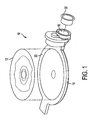
- FIG. 1 is an exploded view of a container 10 that is utilized as a biologically active agent reservoir to be housed in an infuser, not shown.
- the reservoir 10 has a flexible film component 12 covering and sealingly adhered to rigid component 14 along rigid component edge surface 30 for retaining a fluid, such as a liquid biologically active agent or pharmaceutical agent, therein. It is envisioned that a saline solution, or other fluid compositions may also be used.
- the fluid not shown, is dispensed into the interior volume 18, FIG. 5 , through fluid receiving opening 16.
- a hollow conical, funnel-like structure 20 is located within the fluid receiving opening 16.
- the conical structure 20 can help guide a dispensing nozzle 22, see FIG. 9 , to aid in dispensing of the fluid into the interior volume 18, thereby easing the necessity of precisely aligning the opening and the dispensing nozzle.
- Conical structure 20 may be integrally molded or formed in the rigid component 14, or it may be a separate component and inserted into the fluid receiving opening 16 prior to the dispersing of the fluid.
- a filling head with local reservoir evacuation In a standard filing line design a filling head with local reservoir evacuation is used.
- Filling lines traditionally handle cylindrical containers that are easier to orient and are more amenable to filling.
- Such actions are made more difficult or impossible when the standard filling line has to handle non-standard containers. Further complicating this is when the non-standard containers must be filled and sealed under aseptic conditions.
- precise orientation of the container in relation to the filling equipment is important as misalignment can result in wetting of the neck of the container opening.
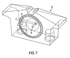
- a container retaining device 24 is used, see FIGS. 6 , 7 and 8 .
- the retaining device 24 can be used separately or combined with other retaining devices in a magazine, not shown, or the retaining device 24 may have interlocking elements thereon, also not shown, to allow the retaining device 24 to mate with others to form a magazine.
- the magazine may resemble a slide tray for a 35mm projector, and may be round, like a carousel, rectangular, square or any other shape desired.
- the reservoir retaining device 24 will allow a dense packing of the reservoirs 10 for the entire sequence of unit operations that occur along a fill and seal line.
- the reservoirs 10 are held securely within the retaining device 24 with their fluid receiving openings 16 oriented to ensure positive location for the fluid dispensing apparatus, preferably automated, see FIG. 9 , and to provide support for any physical contact necessary for the sealing of the reservoir 10 after filling.
- the retaining device 24 may also have teeth along one or more edges, not shown, to provide a means for proper location and orientation of each reservoir under the fluid dispensing apparatus. Alternatively the fluid dispensing apparatus could index with respect to retaining device 24 and the fluid receiving opening 16.
- Another advantage of retaining the container 10 is that the retainer 24 and container 10 may be raised to the filling nozzle 22, see FIG. 9 , rather than the standard method of lowering the fill nozzle, and associated equipment down to the container opening 16. Raising the container 10 to the nozzle 22 minimizes the chances and opportunities for particulate contaminants to become dislodged on overhanging equipment and end up inside the container.
- a magazine especially one in which the retaining device and magazine or integral, provides a preferred means to present irregular, non-standard containers in a traditional fashion to conventional filling technology, especially when those containers take a different form than the reservoirs 10 shown.
- a magazine can achieve a number of specific functions to accomplish this, such as: facilitating transport between filling unit operations; facilitating transport of the reservoirs from the fabrication area to the filling area, including those cases where the parts would be shipped to other manufacturing facilities; positioning and holding the retaining device for filling; providing an optical pathway for drug visualization including the means to back-light and thoroughly inspect through proper lighting; using lights, light pipes, mirrors, etc. for full reservoir inspection; and providing adequate space between reservoirs to ensure full expansion of the flexible sides to provide for specific fill volumes.
- the retaining devices 24 and magazines are also sterilizable and reusable.
- a magazines When used as the shipping container a magazines also provides a means to ensure that the parts arrive undamaged and that they retain their orientation.
- the retaining device 24 itself, whether or not combined into a magazine, can individually also perform these various functions if so desired.
- the aseptic filling and sealing process can preferably be accomplished in the manner described below.
- the non-relaxed state volume 18 of reservoir 10 is preferably greater than the fluid fill volume which is the interior volume of the reservoir 10 when the reservoir 10 has been filled with fluid to its desired and predetermined volume. If a container, different from container 10 is utilized, the non-relaxed state interior volume may or may not be greater than the fill volume.
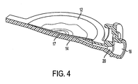
- the expansion of the relaxed state interior volume 17 is accomplished by manipulating the at least one flexible component 12 of container/reservoir 10, which in the embodiments shown is flexible film 12. Flexible film 12 is preferably moved, or expanded, from its relaxed state 17, shown in FIG.
- O-ring 28 creates a seal with the edge surface 30 of container 10.
- the vacuum created within the retaining device hollow space 31 expands flexible component 12 to the container non-relaxed interior volume 18, FIGS. 3 and 5 .
- Flexible component 12 may also be expanded to achieve the fullest interior volume by other means, such as by inflating the interior with a gas through the fluid receiving opening or other opening if the container has one.
- the gas such as an inert gas, for example, can be pushed into the reservoir in any number of ways such as a seal against the reservoir inlet, a jet of air from just above the fluid receiving opening would provide sufficient pressure to inflate the reservoir without making contact. It is preferred that a gas jet or nozzle, with its opening just above the fluid receiving opening, would put out a short puff as the reservoir passes by. This jet of gas will be of sufficient duration to expand the sides of the reservoir for filling.
- the flexible component of the reservoir will generally maintain its shape while the reservoir is empty, since the container is supported while being retained.
- the use of air, or other gases generally requires that the gas be filtered to remove particulate contaminants, especially when an aseptic environment must be maintained.
- the empty container 10 can be tare weighed.
- the expanded container is then raised to a traditional filling dip tube, the dispensing tip of which passes through the fluid receiving opening 16 and the interior volume is filled to a predetermined level range using traditional time based fill control.
- the weight can also be checked to verify proper fill volume.
- the filled container 10 is then placed within an environment capable of enveloping both the fluid containing internal volume and at least the external surface of the flexible component with an area of pressure less than the ambient air pressure, such as a vacuum chamber.
- the air within the vacuum chamber is evacuated to a predetermined pressure range and in a preferred embodiment, a stopper 32 is partially inserted in the fluid receiving opening 16.
- the stopper 32 may contain a small side vent, like a Vacutainer® stopper, or preferably be solid. Alternatively another sealing method may be employed not using a 'stopper'. Since the air is removed from both the interior and exterior of the container 10 no movement of the meniscus within the interior volume occurs due to the balanced pressure. The reduction of pressure does, however, drive out much of the balance of the non-condensable and dissolved gases so care needs to be exercised that the pressure reduction does not cause the fluid within the container 10 to boil. By setting the predetermined pressure range to equal or exceed the vapor pressure of the fluid, boiling should not occur.
- the rate at which the pressure is reduced does not to exceed the rate at which evacuated air can escape the interior of the container through the opening 16 otherwise the fluid will be entrained and expelled by the expanding air.
- This third volume will generally, but not necessarily, be less than the non-relaxed state volume 18, and greater than, equal to, or in some instances, less than the relaxed state volume 17 of the container 10.
- the reduced pressure environment also allows for the manipulation of the flexible component 12 to raise or lower the level of the meniscus so that the headspace volume within the interior comes within a predetermined acceptable range.
- the stopper is driven home to seal the reservoir. Once removed from the vacuum chamber, the apparent headspace collapses at atmospheric pressure and the minute remaining headspace, if any, will generally dissolve into the drug solution.
- the stopper may also be further secured in the port by staking, insertion of a plug that is welded, press fit, glued or by swaging. Once filled, labeling and final packaging occur as is traditionally done.
- Protrusion 11 of non-standard container 10 which in the embodiment shown is a reservoir for a small microinfuser device, is pushed into the protrusion receiving guide 25 of retaining device 24.
- Guide 25 serves to support and help retain reservoir 10.
- Guide 25 also serves to orient reservoir flexible component 12 facing the hollowed out portion 31 of retaining device 24 and the O-ring 28 in contact with the edge surface 30 of the rigid plastic base 14 to which the flexible film 12 is non-releasably attached or affixed.
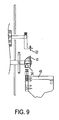
- Retaining device 24 is placed on a lift mechanism 40 which mated with the underside of retaining device 24, not shown, and which also contains gas passages therein which in turn mate with internal gas passages 27 of retainer device 14. Gas passages terminate at port 26.
- a vacuum source in fluid communication with the lifting mechanism 40 and retaining device 24, is activated causing flexible film 12 to be pulled into the hollow space 31 and thereby expanding the interior volume of reservoir 10 from its collapsed, relaxed state to an expanded non-relaxed, or stretched state.
- Lift mechanism 40 raises retaining device 24 and reservoir 10 retained therein up to a fluid dispensing nozzle or needle 41 until the fluid dispensing needle 41 is within fluid receiving opening 16.
- Conical structure 20 acts as a guide for dispensing needle 41 to assure proper positioning for filling. Fluid dispensing needle 41 dispenses a predetermined amount of fluid into the interior volume of reservoir 10 as is known in the art.
- Lifting mechanism 40 then lowers the retaining device 24 and retained reservoir 10 away from fluid dispensing needle 41 after the fluid has been dispensed therein.
- Lift mechanism 40 then positions the retaining device 24 and fluid filled reservoir 10 into an vacuum chamber to create an environment of air pressure less than that of the ambient air pressure on both the external surfaces and internal surfaces of the reservoir 10 and fluid contained therein.
- flexible component 12 is flexed to raise or lower the fluid meniscus and the associated headspace volume to a predetermined range of acceptable limits. Once the meniscus level has been attained the fluid receiving opening is stoppered and sealed.
- the retaining device 24 for releasably retaining the container 10 can be modified or design to releasable retain the device in which the container 10 itself is housed, such as an assembled or partially assembled microinfuser for example.
Landscapes
- Mechanical Engineering (AREA)
- Health & Medical Sciences (AREA)
- Engineering & Computer Science (AREA)
- Life Sciences & Earth Sciences (AREA)
- Dispersion Chemistry (AREA)
- Pharmacology & Pharmacy (AREA)
- Chemical & Material Sciences (AREA)
- Animal Behavior & Ethology (AREA)
- General Health & Medical Sciences (AREA)
- Public Health (AREA)
- Veterinary Medicine (AREA)
- Basic Packing Technique (AREA)
- Vacuum Packaging (AREA)
- Medical Preparation Storing Or Oral Administration Devices (AREA)
Claims (10)
- Verfahren zum Befüllen und Abdichten von Behältern (10) mit mindestens einer Fluidaufnahmeöffnung (16), mindestens einem flexiblen Teil (12), mindestens einem starren Teil (14), einem Innenvolumen (17) im entspannten Zustand und einem Innenvolumen (17) im nicht entspannten Zustand, wobei das Volumen (18) im nicht entspannten Zustand größer als das Volumen (18) im entspannten Zustand ist, und wobei das mindestens eine flexible Teil mindestens eine Außenfläche und mindestens eine Innenfläche aufweist, und wobei der Behälter (10) durch das Zusammenfügen des starren Teils (14) und des flexiblen Teils (12) gebildet wird, wobei das Verfahren aufweist:lösbares Halten des Behälters, wobei das Halten das Bewegen des mindestens einen flexiblen Teils ermöglicht;Positionieren des gehaltenen Behälters (10) in einer Position zur Aufnahme eines in diesem zu haltenden Fluids über die mindestens eine Fluidaufnahmeöffnung (16);Ausdehnen des im entspannten Zustand eingenommenen Innenvolumens (17) des Behälters zu dem im nicht entspannten Zustand eingenommenen Innenvolumen (18);Ausgeben eines Fluids in das im nicht entspannten Zustand eingenommene Innenvolumen des Behälters;Aussetzen sowohl der Außenseite des mindestens einen flexiblen Teils (12), als auch des Innenvolumens des Fluid enthaltenden Behälters einer Umgebung, die einen vorbestimmten Druckbereich aufweist, wobei der Druckbereich größer oder gleich dem Dampfdruck des Fluids in dem Behälter ist;Abdichten der mindestens einen Fluidaufnahmeöffnung (16) während sich das Innenvolumen und die Außenseite des flexiblen Teils innerhalb des vorbestimmten Druckbereichs befinden;Erhöhen des Drucks der Umgebung auf den umgebenden Atmosphärendruck; undLösen des Behälters aus der lösbar gehaltenen Position.
- Verfahren nach Anspruch 1, bei welchem die Schritte unter aseptischen Bedingungen durchgeführt werden.
- Verfahren nach Anspruch 1, bei welchem die Schritte in der genannten Reihenfolge durchgeführt werden.
- Verfahren nach Anspruch 1, bei welchem die Schritte im Wesentlichen gleichzeitig durchgeführt werden.
- Verfahren nach Anspruch 1, bei welchem das Ausdehnen des im entspannten Zustand eingenommenen Innenvolumens des Behälters zu dem im nicht entspannten Zustand eingenommenen Innenvolumen durch das Biegen des mindestens einen flexiblen Teils (12) erfolgt.
- Verfahren nach Anspruch 1, bei welchem das Ausdehnen des im entspannten Zustand eingenommenen Innenvolumens des Behälters zu dem im nicht entspannten Zustand eingenommenen Innenvolumen durch das Injizieren eines Gases in das Innenvolumen (18) des Behälters erfolgt.
- Verfahren nach Anspruch 1, bei welchem das Ausdehnen des im entspannten Zustand eingenommenen Innenvolumens des Behälters zu dem im nicht entspannten Zustand eingenommenen Innenvolumen durch das Beaufschlagen der Außenseite des flexiblen Teils mit Unterdruck oder verringertem Druck erfolgt.
- Verfahren nach Anspruch 1, bei welchem das Ausdehnen des im entspannten Zustand eingenommenen Innenvolumens des Behälters zu dem im nicht entspannten Zustand eingenommenen Innenvolumen durch physische Handhabung des flexiblen Teils erfolgt.
- Verfahren nach Anspruch 1, bei welchem die Schritte des Ausgebens und des Abdichtens an separaten physischen Stellen durchgeführt werden.
- Verfahren nach Anspruch 1, ferner mit dem Einführen einer Fluidausgabedüse (22) in die mindestens eine Fluidaufnahmeöffnung (16) vor dem Ausgeben des Fluids.
Applications Claiming Priority (3)
| Application Number | Priority Date | Filing Date | Title |
|---|---|---|---|
| US41627702P | 2002-10-07 | 2002-10-07 | |
| US416277P | 2002-10-07 | ||
| PCT/US2003/031758 WO2004033954A2 (en) | 2002-10-07 | 2003-10-07 | Method for filling a container having at least one flexible component |
Publications (3)
| Publication Number | Publication Date |
|---|---|
| EP1556646A2 EP1556646A2 (de) | 2005-07-27 |
| EP1556646A4 EP1556646A4 (de) | 2007-06-20 |
| EP1556646B1 true EP1556646B1 (de) | 2013-12-18 |
Family
ID=32093836
Family Applications (1)
| Application Number | Title | Priority Date | Filing Date |
|---|---|---|---|
| EP03774628.6A Expired - Lifetime EP1556646B1 (de) | 2002-10-07 | 2003-10-07 | Verfahren zum füllen eines behälters mit mindestens einer flexiblen komponente |
Country Status (6)
| Country | Link |
|---|---|
| US (3) | US7024836B2 (de) |
| EP (1) | EP1556646B1 (de) |
| JP (1) | JP4460452B2 (de) |
| AU (1) | AU2003282742A1 (de) |
| ES (1) | ES2449715T3 (de) |
| WO (1) | WO2004033954A2 (de) |
Families Citing this family (25)
| Publication number | Priority date | Publication date | Assignee | Title |
|---|---|---|---|---|
| EP1556646B1 (de) * | 2002-10-07 | 2013-12-18 | Becton, Dickinson and Company | Verfahren zum füllen eines behälters mit mindestens einer flexiblen komponente |
| SE525952C2 (sv) * | 2003-10-02 | 2005-05-31 | Eco Lean Res & Dev As | Metod och anordning för gasfyllning och försegling av en för gasfyllning avsedd kanal i en förpackning av kollapsande slag, samt ett förpackningsämne innefattande en sådan kanal |
| EP2077132A1 (de) | 2008-01-02 | 2009-07-08 | Boehringer Ingelheim Pharma GmbH & Co. KG | Abgabevorrichtung, Aufbewahrungsvorrichtung und Verfahren zur Abgabe einer Formulierung |
| SG189681A1 (en) | 2008-03-17 | 2013-05-31 | Boehringer Ingelheim Int | Reservoir and nebulizer |
| US10011906B2 (en) | 2009-03-31 | 2018-07-03 | Beohringer Ingelheim International Gmbh | Method for coating a surface of a component |
| EP2432531B1 (de) | 2009-05-18 | 2019-03-06 | Boehringer Ingelheim International GmbH | Adapter, inhalationseinrichtung und zerstäuber |
| NZ599295A (en) | 2009-11-25 | 2014-06-27 | Boehringer Ingelheim Int | Nebulizer |
| US10016568B2 (en) | 2009-11-25 | 2018-07-10 | Boehringer Ingelheim International Gmbh | Nebulizer |
| EP2504051B1 (de) | 2009-11-25 | 2019-09-04 | Boehringer Ingelheim International GmbH | Zerstäuber |
| US9943654B2 (en) | 2010-06-24 | 2018-04-17 | Boehringer Ingelheim International Gmbh | Nebulizer |
| EP2694220B1 (de) | 2011-04-01 | 2020-05-06 | Boehringer Ingelheim International GmbH | Medizinisches gerät mit behälter |
| US9827384B2 (en) | 2011-05-23 | 2017-11-28 | Boehringer Ingelheim International Gmbh | Nebulizer |
| WO2013152894A1 (de) | 2012-04-13 | 2013-10-17 | Boehringer Ingelheim International Gmbh | Zerstäuber mit kodiermitteln |
| FR3003550B1 (fr) * | 2013-03-22 | 2016-05-06 | Sartorius Stedim North America Inc | Installation et procede pour la preparation d'un conteneur charge avec un fluide biopharmaceutique. |
| WO2015018904A1 (en) | 2013-08-09 | 2015-02-12 | Boehringer Ingelheim International Gmbh | Nebulizer |
| EP2835146B1 (de) | 2013-08-09 | 2020-09-30 | Boehringer Ingelheim International GmbH | Zerstäuber |
| US9027877B1 (en) * | 2014-04-10 | 2015-05-12 | Google Inc. | Filling apparatus for high-altitude balloons |
| EP3139979B1 (de) | 2014-05-07 | 2023-07-05 | Boehringer Ingelheim International GmbH | Einheit, zerstäuber und verfahren |
| BR112016023932B1 (pt) | 2014-05-07 | 2022-11-29 | Boehringer Ingelheim International Gmbh | Nebulizador |
| DK3139984T3 (da) | 2014-05-07 | 2021-07-19 | Boehringer Ingelheim Int | Forstøver |
| ES2549694B9 (es) * | 2014-10-23 | 2017-01-04 | Grifols, S.A. | Procedimiento de llenado aséptico de una bolsa |
| US9963216B1 (en) | 2016-02-26 | 2018-05-08 | X Development Llc | Filling apparatus for high-altitude balloons |
| US10576018B2 (en) * | 2016-07-19 | 2020-03-03 | Carefusion 303, Inc. | Reconstitution device for IV fluids and method of use |
| US11724087B2 (en) * | 2018-09-11 | 2023-08-15 | Becton, Dickinson And Company | Catheter priming devices, systems and methods |
| KR102264137B1 (ko) * | 2020-09-22 | 2021-06-22 | 대한민국(기상청 국립기상과학원장) | 레윈존데 기구의 파손을 방지하는 회전형 기체 주입 장치 |
Family Cites Families (44)
| Publication number | Priority date | Publication date | Assignee | Title |
|---|---|---|---|---|
| US1931911A (en) * | 1929-10-02 | 1933-10-24 | White Cap Co | Packing method and apparatus |
| US2713543A (en) * | 1951-10-10 | 1955-07-19 | Peters Leo | Beverage package |
| US2831510A (en) * | 1955-02-28 | 1958-04-22 | Clarence F Carter | Filling machine for open mouth bags |
| US3092939A (en) * | 1960-11-25 | 1963-06-11 | Welty Frank | Bulk beverage dispenser and method of preparing same |
| US3299603A (en) * | 1962-03-12 | 1967-01-24 | Continental Can Co | Method of filling pouches |
| US3382642A (en) * | 1965-10-14 | 1968-05-14 | Continental Can Co | Method of filling pouches |
| US4001450A (en) * | 1967-08-01 | 1977-01-04 | Imperial Chemical Industries Limited | Method of packaging carbonated beverages in flexible containers |
| GB1251672A (de) * | 1968-02-29 | 1971-10-27 | ||
| US3722557A (en) * | 1971-03-03 | 1973-03-27 | Baxter Laboratories Inc | Apparatus for adding medicaments to a sealed expandable parenteral fluid container |
| GB1420951A (en) * | 1972-03-28 | 1976-01-14 | Ici Ltd | Method and apparatus for filling and sealing plastics containers |
| US3965946A (en) * | 1975-03-06 | 1976-06-29 | Abbott Laboratories | Vacuum device for an expandable container |
| US4060107A (en) * | 1976-10-26 | 1977-11-29 | Henry Naftulin | Method and apparatus for collecting fluids |
| US4176153A (en) * | 1978-02-10 | 1979-11-27 | Automatic Liquid Packaging, Inc. | Unitary, hermetically-sealed but pierceable dispensing container |
| JPS56113528A (en) * | 1980-02-05 | 1981-09-07 | Dainippon Printing Co Ltd | Germless filling method |
| US4363338A (en) * | 1980-09-08 | 1982-12-14 | Brown Albert M | Liquid filling machine |
| US4448228A (en) * | 1981-01-09 | 1984-05-15 | Aisin Seiki Kabushiki Kaisha | Air bag system having a branched joint |
| CA1182269A (en) * | 1981-08-18 | 1985-02-12 | Wrightcel Limited | Aseptic filling station |
| US4478025A (en) * | 1981-08-31 | 1984-10-23 | Scanlan Gregory P | Vacuum packing device |
| US4524563A (en) * | 1981-12-10 | 1985-06-25 | Tito Manzini & Figli S.P.A. | Process and plant for aseptic filling of pre-sterilized, non-rigid containers |
| US4633654A (en) * | 1984-07-10 | 1987-01-06 | Tokyo Automatic Machinery Works, Ltd. | Air extractor for bag making, filling and packaging machine |
| SE448444B (sv) * | 1985-07-08 | 1987-02-23 | Alfa Laval Food & Dairy Eng | Forslutbar pase samt anvendning av denna |
| DE3602075C1 (de) * | 1986-01-24 | 1987-07-23 | Fresenius Ag | Verfahren und Vorrichtung zum Herstellen von Gemischen pharmazeutischer Fluessigkeiten |
| US4856261A (en) * | 1986-11-27 | 1989-08-15 | Courtaulds Packaging Australia Limited | Forming small flexible containers |
| US4840017A (en) * | 1987-08-03 | 1989-06-20 | Baxter Healthcare Corporation | Method for filling collapsible containers |
| US5428943A (en) | 1988-09-14 | 1995-07-04 | Kal Kan Foods, Inc. | Method of filling and sealing a deformable container |
| GB8824925D0 (en) * | 1988-10-25 | 1988-11-30 | Bowater Packaging Ltd | Aseptic filling apparatus |
| US4924919A (en) * | 1988-11-03 | 1990-05-15 | Balloon Wrap, Inc. | Method of filling a balloon with articles and air |
| US4964261A (en) * | 1989-01-24 | 1990-10-23 | Benn James A | Bag filling method and apparatus for preparing pharmaceutical sterile solutions |
| US5159895A (en) * | 1990-07-09 | 1992-11-03 | Helling Robert W | Packaged article assembly |
| US5170609A (en) * | 1991-01-22 | 1992-12-15 | Hershey Foods Corporation | Fluidic deflator means and method for article packaging |
| US5205109A (en) * | 1991-12-23 | 1993-04-27 | Conway Matthew J | Method and apparatus for expanding a balloon and accessing the interior thereof |
| US5267575A (en) * | 1992-08-05 | 1993-12-07 | C.A.R.E. Of Nevada | User-activated vacuum-assisted condom applicator |
| US5535584A (en) * | 1993-10-19 | 1996-07-16 | California Energy Commission | Performance enhanced gas turbine powerplants |
| SE502182C2 (sv) * | 1994-02-15 | 1995-09-11 | Tetra Laval Holdings & Finance | Fyllning av förpackningsbehållare till en expanderad form varefter fyllgods återsugs så att förpackningen får en förutbestämd volym. |
| DE4439231C1 (de) * | 1994-11-03 | 1996-04-25 | Bernd Hansen | Blasformverfahren zum Herstellen eines verschlossenen Behältnisses und nach diesem Verfahren hergestelltes Behältnis |
| DE19526743A1 (de) * | 1995-07-21 | 1997-01-23 | Wacker Chemie Gmbh | Verfahren zum Befüllen und Entleeren eines Behälters |
| US5806572A (en) * | 1996-03-06 | 1998-09-15 | Voller; Ronald L. | Apparatus for inflating and deflating a dunnage bag |
| US5901865A (en) * | 1996-04-23 | 1999-05-11 | Automatic Liquid Packaging, Inc. | Hermetically sealed container with frangible web and locking lugs and method and apparatus for making same |
| US5673731A (en) * | 1996-05-03 | 1997-10-07 | Morton International, Inc. | Method and apparatus for filling elongated pressurized fluid containers from the side |
| FR2764544B1 (fr) * | 1997-06-16 | 1999-09-24 | Sidel Sa | Tuyere de soufflage de recipients en matiere plastique et installation pourvue d'une telle tuyere |
| US5873764A (en) * | 1998-03-12 | 1999-02-23 | Scherr; Mark J. | Side evacuating balloon inflater |
| IT1311103B1 (it) * | 1999-10-20 | 2002-02-28 | Ulisse Rapparini | Confezionatrice automatica per il condizionamento di sacchetti inatmosfera controllata. |
| US6877533B2 (en) * | 2002-02-11 | 2005-04-12 | Roskam Automatic Machinery, Inc. | Void-fill bag filling system and method |
| EP1556646B1 (de) * | 2002-10-07 | 2013-12-18 | Becton, Dickinson and Company | Verfahren zum füllen eines behälters mit mindestens einer flexiblen komponente |
-
2003
- 2003-10-07 EP EP03774628.6A patent/EP1556646B1/de not_active Expired - Lifetime
- 2003-10-07 WO PCT/US2003/031758 patent/WO2004033954A2/en not_active Ceased
- 2003-10-07 ES ES03774628.6T patent/ES2449715T3/es not_active Expired - Lifetime
- 2003-10-07 AU AU2003282742A patent/AU2003282742A1/en not_active Abandoned
- 2003-10-07 JP JP2004543470A patent/JP4460452B2/ja not_active Expired - Lifetime
- 2003-10-07 US US10/679,271 patent/US7024836B2/en not_active Expired - Lifetime
-
2006
- 2006-02-22 US US11/359,351 patent/US7150138B2/en not_active Expired - Lifetime
- 2006-11-08 US US11/557,798 patent/US20070095424A1/en not_active Abandoned
Also Published As
| Publication number | Publication date |
|---|---|
| WO2004033954A3 (en) | 2004-05-27 |
| AU2003282742A1 (en) | 2004-05-04 |
| AU2003282742A8 (en) | 2004-05-04 |
| ES2449715T3 (es) | 2014-03-20 |
| JP4460452B2 (ja) | 2010-05-12 |
| US20040139700A1 (en) | 2004-07-22 |
| US7150138B2 (en) | 2006-12-19 |
| US20060137297A1 (en) | 2006-06-29 |
| JP2006502061A (ja) | 2006-01-19 |
| US20070095424A1 (en) | 2007-05-03 |
| WO2004033954A2 (en) | 2004-04-22 |
| US7024836B2 (en) | 2006-04-11 |
| EP1556646A2 (de) | 2005-07-27 |
| EP1556646A4 (de) | 2007-06-20 |
Similar Documents
| Publication | Publication Date | Title |
|---|---|---|
| EP1556646B1 (de) | Verfahren zum füllen eines behälters mit mindestens einer flexiblen komponente | |
| CA2398921C (en) | Process of bulk filling | |
| US11560267B2 (en) | Evacuated bottle system | |
| US8919392B2 (en) | Container filling assembly | |
| US20070175538A1 (en) | System and method for filling containers with liquid under varying pressure conditions | |
| US6099510A (en) | Device for withdrawing a liquid from a sealed glass ampoule | |
| CN107530489A (zh) | 用于密封盒的支撑结构、运输或包装容器以及过程 | |
| WO2013055988A1 (en) | Liner-based shipping and dispensing containers for the substantially sterile storage, shipment, and dispense of materials | |
| AU2002211780A1 (en) | Process of bulk filling | |
| EP2763645B1 (de) | Verfahren und vorrichtung zur herstellung einer kapsel | |
| JP2929575B2 (ja) | 密封したガラスアンプルから液体を取り出す方法と装置 | |
| JPH0775672A (ja) | 薬品容器兼注射器における注射筒本体 | |
| JPH07124257A (ja) | 密封容器とその製造方法 | |
| US3719213A (en) | Method for adding medicaments to a sealed expandable parenteral fluid container | |
| JPH0775673A (ja) | 薬品容器兼注射器における注射筒本体 | |
| JPH0780064A (ja) | 薬品容器兼注射器における注射筒本体 | |
| JP3243914B2 (ja) | 密封容器の残存気泡溶解方法 | |
| JPH07124230A (ja) | 容器への中栓打栓方法 | |
| CN117985308A (zh) | 从外包装移出无菌物体的装置、方法和包括该装置的系统 | |
| JP2015066272A (ja) | 注射筒傾き抑制持具 |
Legal Events
| Date | Code | Title | Description |
|---|---|---|---|
| PUAI | Public reference made under article 153(3) epc to a published international application that has entered the european phase |
Free format text: ORIGINAL CODE: 0009012 |
|
| 17P | Request for examination filed |
Effective date: 20050418 |
|
| AK | Designated contracting states |
Kind code of ref document: A2 Designated state(s): AT BE BG CH CY CZ DE DK EE ES FI FR GB GR HU IE IT LI LU MC NL PT RO SE SI SK TR |
|
| AX | Request for extension of the european patent |
Extension state: AL LT LV MK |
|
| RIC1 | Information provided on ipc code assigned before grant |
Ipc: 7B 67B 1/00 A |
|
| DAX | Request for extension of the european patent (deleted) | ||
| A4 | Supplementary search report drawn up and despatched |
Effective date: 20070521 |
|
| RIC1 | Information provided on ipc code assigned before grant |
Ipc: B65B 31/02 20060101ALI20070515BHEP Ipc: B67B 1/00 20060101AFI20050921BHEP Ipc: B65B 3/00 20060101ALI20070515BHEP |
|
| 17Q | First examination report despatched |
Effective date: 20100923 |
|
| GRAP | Despatch of communication of intention to grant a patent |
Free format text: ORIGINAL CODE: EPIDOSNIGR1 |
|
| INTG | Intention to grant announced |
Effective date: 20130701 |
|
| GRAS | Grant fee paid |
Free format text: ORIGINAL CODE: EPIDOSNIGR3 |
|
| GRAA | (expected) grant |
Free format text: ORIGINAL CODE: 0009210 |
|
| AK | Designated contracting states |
Kind code of ref document: B1 Designated state(s): AT BE BG CH CY CZ DE DK EE ES FI FR GB GR HU IE IT LI LU MC NL PT RO SE SI SK TR |
|
| REG | Reference to a national code |
Ref country code: GB Ref legal event code: FG4D |
|
| REG | Reference to a national code |
Ref country code: CH Ref legal event code: EP |
|
| REG | Reference to a national code |
Ref country code: AT Ref legal event code: REF Ref document number: 645538 Country of ref document: AT Kind code of ref document: T Effective date: 20140115 |
|
| REG | Reference to a national code |
Ref country code: IE Ref legal event code: FG4D |
|
| REG | Reference to a national code |
Ref country code: DE Ref legal event code: R096 Ref document number: 60345468 Country of ref document: DE Effective date: 20140206 |
|
| REG | Reference to a national code |
Ref country code: ES Ref legal event code: FG2A Ref document number: 2449715 Country of ref document: ES Kind code of ref document: T3 Effective date: 20140320 |
|
| REG | Reference to a national code |
Ref country code: NL Ref legal event code: VDEP Effective date: 20131218 |
|
| PG25 | Lapsed in a contracting state [announced via postgrant information from national office to epo] |
Ref country code: FI Free format text: LAPSE BECAUSE OF FAILURE TO SUBMIT A TRANSLATION OF THE DESCRIPTION OR TO PAY THE FEE WITHIN THE PRESCRIBED TIME-LIMIT Effective date: 20131218 Ref country code: SE Free format text: LAPSE BECAUSE OF FAILURE TO SUBMIT A TRANSLATION OF THE DESCRIPTION OR TO PAY THE FEE WITHIN THE PRESCRIBED TIME-LIMIT Effective date: 20131218 |
|
| REG | Reference to a national code |
Ref country code: AT Ref legal event code: MK05 Ref document number: 645538 Country of ref document: AT Kind code of ref document: T Effective date: 20131218 |
|
| PG25 | Lapsed in a contracting state [announced via postgrant information from national office to epo] |
Ref country code: EE Free format text: LAPSE BECAUSE OF FAILURE TO SUBMIT A TRANSLATION OF THE DESCRIPTION OR TO PAY THE FEE WITHIN THE PRESCRIBED TIME-LIMIT Effective date: 20131218 Ref country code: BE Free format text: LAPSE BECAUSE OF FAILURE TO SUBMIT A TRANSLATION OF THE DESCRIPTION OR TO PAY THE FEE WITHIN THE PRESCRIBED TIME-LIMIT Effective date: 20131218 |
|
| PG25 | Lapsed in a contracting state [announced via postgrant information from national office to epo] |
Ref country code: NL Free format text: LAPSE BECAUSE OF FAILURE TO SUBMIT A TRANSLATION OF THE DESCRIPTION OR TO PAY THE FEE WITHIN THE PRESCRIBED TIME-LIMIT Effective date: 20131218 Ref country code: AT Free format text: LAPSE BECAUSE OF FAILURE TO SUBMIT A TRANSLATION OF THE DESCRIPTION OR TO PAY THE FEE WITHIN THE PRESCRIBED TIME-LIMIT Effective date: 20131218 Ref country code: SK Free format text: LAPSE BECAUSE OF FAILURE TO SUBMIT A TRANSLATION OF THE DESCRIPTION OR TO PAY THE FEE WITHIN THE PRESCRIBED TIME-LIMIT Effective date: 20131218 Ref country code: CZ Free format text: LAPSE BECAUSE OF FAILURE TO SUBMIT A TRANSLATION OF THE DESCRIPTION OR TO PAY THE FEE WITHIN THE PRESCRIBED TIME-LIMIT Effective date: 20131218 Ref country code: PT Free format text: LAPSE BECAUSE OF FAILURE TO SUBMIT A TRANSLATION OF THE DESCRIPTION OR TO PAY THE FEE WITHIN THE PRESCRIBED TIME-LIMIT Effective date: 20140418 Ref country code: RO Free format text: LAPSE BECAUSE OF FAILURE TO SUBMIT A TRANSLATION OF THE DESCRIPTION OR TO PAY THE FEE WITHIN THE PRESCRIBED TIME-LIMIT Effective date: 20131218 Ref country code: CY Free format text: LAPSE BECAUSE OF FAILURE TO SUBMIT A TRANSLATION OF THE DESCRIPTION OR TO PAY THE FEE WITHIN THE PRESCRIBED TIME-LIMIT Effective date: 20131218 |
|
| REG | Reference to a national code |
Ref country code: DE Ref legal event code: R097 Ref document number: 60345468 Country of ref document: DE |
|
| PLBE | No opposition filed within time limit |
Free format text: ORIGINAL CODE: 0009261 |
|
| STAA | Information on the status of an ep patent application or granted ep patent |
Free format text: STATUS: NO OPPOSITION FILED WITHIN TIME LIMIT |
|
| PG25 | Lapsed in a contracting state [announced via postgrant information from national office to epo] |
Ref country code: DK Free format text: LAPSE BECAUSE OF FAILURE TO SUBMIT A TRANSLATION OF THE DESCRIPTION OR TO PAY THE FEE WITHIN THE PRESCRIBED TIME-LIMIT Effective date: 20131218 |
|
| 26N | No opposition filed |
Effective date: 20140919 |
|
| REG | Reference to a national code |
Ref country code: DE Ref legal event code: R097 Ref document number: 60345468 Country of ref document: DE Effective date: 20140919 |
|
| REG | Reference to a national code |
Ref country code: HU Ref legal event code: AG4A Ref document number: E021708 Country of ref document: HU |
|
| PG25 | Lapsed in a contracting state [announced via postgrant information from national office to epo] |
Ref country code: SI Free format text: LAPSE BECAUSE OF FAILURE TO SUBMIT A TRANSLATION OF THE DESCRIPTION OR TO PAY THE FEE WITHIN THE PRESCRIBED TIME-LIMIT Effective date: 20131218 Ref country code: MC Free format text: LAPSE BECAUSE OF FAILURE TO SUBMIT A TRANSLATION OF THE DESCRIPTION OR TO PAY THE FEE WITHIN THE PRESCRIBED TIME-LIMIT Effective date: 20131218 Ref country code: LU Free format text: LAPSE BECAUSE OF FAILURE TO SUBMIT A TRANSLATION OF THE DESCRIPTION OR TO PAY THE FEE WITHIN THE PRESCRIBED TIME-LIMIT Effective date: 20141007 |
|
| REG | Reference to a national code |
Ref country code: CH Ref legal event code: PL |
|
| REG | Reference to a national code |
Ref country code: IE Ref legal event code: MM4A |
|
| PG25 | Lapsed in a contracting state [announced via postgrant information from national office to epo] |
Ref country code: LI Free format text: LAPSE BECAUSE OF NON-PAYMENT OF DUE FEES Effective date: 20141031 Ref country code: CH Free format text: LAPSE BECAUSE OF NON-PAYMENT OF DUE FEES Effective date: 20141031 |
|
| PG25 | Lapsed in a contracting state [announced via postgrant information from national office to epo] |
Ref country code: IE Free format text: LAPSE BECAUSE OF NON-PAYMENT OF DUE FEES Effective date: 20141007 |
|
| PG25 | Lapsed in a contracting state [announced via postgrant information from national office to epo] |
Ref country code: BG Free format text: LAPSE BECAUSE OF FAILURE TO SUBMIT A TRANSLATION OF THE DESCRIPTION OR TO PAY THE FEE WITHIN THE PRESCRIBED TIME-LIMIT Effective date: 20131218 |
|
| PG25 | Lapsed in a contracting state [announced via postgrant information from national office to epo] |
Ref country code: GR Free format text: LAPSE BECAUSE OF FAILURE TO SUBMIT A TRANSLATION OF THE DESCRIPTION OR TO PAY THE FEE WITHIN THE PRESCRIBED TIME-LIMIT Effective date: 20140319 |
|
| PG25 | Lapsed in a contracting state [announced via postgrant information from national office to epo] |
Ref country code: TR Free format text: LAPSE BECAUSE OF FAILURE TO SUBMIT A TRANSLATION OF THE DESCRIPTION OR TO PAY THE FEE WITHIN THE PRESCRIBED TIME-LIMIT Effective date: 20131218 |
|
| REG | Reference to a national code |
Ref country code: FR Ref legal event code: PLFP Year of fee payment: 14 |
|
| REG | Reference to a national code |
Ref country code: FR Ref legal event code: PLFP Year of fee payment: 15 |
|
| REG | Reference to a national code |
Ref country code: FR Ref legal event code: PLFP Year of fee payment: 16 |
|
| PGFP | Annual fee paid to national office [announced via postgrant information from national office to epo] |
Ref country code: GB Payment date: 20220922 Year of fee payment: 20 |
|
| PGFP | Annual fee paid to national office [announced via postgrant information from national office to epo] |
Ref country code: FR Payment date: 20220921 Year of fee payment: 20 |
|
| PGFP | Annual fee paid to national office [announced via postgrant information from national office to epo] |
Ref country code: IT Payment date: 20220920 Year of fee payment: 20 Ref country code: ES Payment date: 20221102 Year of fee payment: 20 Ref country code: DE Payment date: 20220616 Year of fee payment: 20 |
|
| PGFP | Annual fee paid to national office [announced via postgrant information from national office to epo] |
Ref country code: HU Payment date: 20221001 Year of fee payment: 20 |
|
| REG | Reference to a national code |
Ref country code: DE Ref legal event code: R071 Ref document number: 60345468 Country of ref document: DE |
|
| REG | Reference to a national code |
Ref country code: ES Ref legal event code: FD2A Effective date: 20231026 |
|
| REG | Reference to a national code |
Ref country code: GB Ref legal event code: PE20 Expiry date: 20231006 |
|
| PG25 | Lapsed in a contracting state [announced via postgrant information from national office to epo] |
Ref country code: GB Free format text: LAPSE BECAUSE OF EXPIRATION OF PROTECTION Effective date: 20231006 |
|
| PG25 | Lapsed in a contracting state [announced via postgrant information from national office to epo] |
Ref country code: ES Free format text: LAPSE BECAUSE OF EXPIRATION OF PROTECTION Effective date: 20231008 |
|
| PG25 | Lapsed in a contracting state [announced via postgrant information from national office to epo] |
Ref country code: GB Free format text: LAPSE BECAUSE OF EXPIRATION OF PROTECTION Effective date: 20231006 Ref country code: ES Free format text: LAPSE BECAUSE OF EXPIRATION OF PROTECTION Effective date: 20231008 |