EP1556225B1 - Modularer drucker - Google Patents
Modularer drucker Download PDFInfo
- Publication number
- EP1556225B1 EP1556225B1 EP03776958A EP03776958A EP1556225B1 EP 1556225 B1 EP1556225 B1 EP 1556225B1 EP 03776958 A EP03776958 A EP 03776958A EP 03776958 A EP03776958 A EP 03776958A EP 1556225 B1 EP1556225 B1 EP 1556225B1
- Authority
- EP
- European Patent Office
- Prior art keywords
- control means
- module
- electronic control
- printer
- carrying member
- Prior art date
- Legal status (The legal status is an assumption and is not a legal conclusion. Google has not performed a legal analysis and makes no representation as to the accuracy of the status listed.)
- Expired - Lifetime
Links
Images




Classifications
-
- B—PERFORMING OPERATIONS; TRANSPORTING
- B41—PRINTING; LINING MACHINES; TYPEWRITERS; STAMPS
- B41J—TYPEWRITERS; SELECTIVE PRINTING MECHANISMS, i.e. MECHANISMS PRINTING OTHERWISE THAN FROM A FORME; CORRECTION OF TYPOGRAPHICAL ERRORS
- B41J29/00—Details of, or accessories for, typewriters or selective printing mechanisms not otherwise provided for
Definitions
- the invention is in the field of thermal printing printers. It relates to a printer composed of a plurality of modules whose assembly between them allows to decline a range of separate printers.
- a thermal printing printer mainly comprises a reservoir of a roll-conditioned printing tape, associated with means necessary for conveying the tape and printing it by heating points.
- the problem that the present invention seeks to solve lies in optimizing the use of all or part of the participating components of the printer.
- the object of the present invention is to propose a modular thermal printing printer whose structure makes it possible to respond to the aforementioned problems.
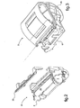
- the second carrier member comprises a first support 9 equipped with cooperating means with first elementary easily reversible interlocking means equipping the first carrier member 17.
- This first support 9 carries the control means 30,31, as well as first electronic control means 11 and means 19, 35, 36 in related relation.
- the second carrier member comprises, not only the first support 9, but also a second support 10 arranged in appearance cover, styling in particular the third module 3 carrying the printing mechanism 4, and the first support 9 of the second module 2.
- this aspect cover 10 advantageously comprises a peripheral shoulder 27 in the middle zone of its thickness, in particular for a configuration of the printer of the invention as a panel printer, or for the receiving a rear closure shell 26 against which the lid, in alternative configurations, adopts a plane support via its peripheral shoulder 27.
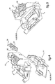
- the second support advantageously constituted by the appearance cover 10 carries second electronic control means 12, 12 'and associated linking means 19, 34, 35, 36. It will be understood that these means 12, 12 'and 19, 34, 35, 36 are substituting electronic control means 11 and associated linking means 19, 34, 35, 36 supported by the first support 9.
- This second support 10 is equipped with means cooperating with second easily reversible elementary fitting means fitted to the first carrier member 17.
- These second electronic control means 12, 12 'and the associated rotating means 19, 34, 35, 36 comprise analogous means to the first electronic control means 11 and to the associated first associating means, for the purposes of said substitution, completed by associated means comprising at least one of the specific management means 14 of the source of electrical energy 20,21, specific electronic control means 15 participating general printing control means and information memory means 16 transmitted remotely by the remote printing control means 6.
- the second electronic control means comprise electronic means 12, 12 'of alternative elementary control by substitution, which are supported by the second support 10.
- First elementary means 12 of these second electronic control means are equipped with connection means 34 with an autonomous source 20 of electrical energy, while second elementary means 12 'of these second control means are equipped with means of control. connection 19 with the power supply network 21 in electrical energy.
- the second support which consists mainly of the appearance cover 10, is easily reversible on the first carrier member 17.
- an electronic card 22, 29 carrying the second means 12,12 'control electronics completed by the means 14, 15, 16 associated is preferably also reported by interlocking easily reversible to the rear face of the cover 10, and behind the first carrier member 17.
- the autonomous source of electrical energy 20 comprises at least one battery carried by the rear face of the electronic card 29.
- the latter 29 is further carrying the first elementary means 12 of the second electronic control means and 34,35,36 associated linking means.
- This battery 20 is advantageously housed in a space between the shell 26 and the electronic card 29, the latter 29 forming a separating partition mechanically and electrostatically protecting the printing mechanisms 4 and control means 12.
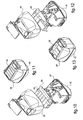
- the shell 26 is preferably equipped on its rear face of easily reversible interlocking means with a base 33, such as a wall or table base shown in Fig.14.
- control means comprise for example at least one pusher 30 for implementing the driving means 7 for driving the strip, and at least one pusher 31 for setting the of the printing mechanism 4, associated with a display means 32 of the operating state of the printer
- the knife 23 is preferably mounted in an easily reversible manner on the frame 5 of the first module 1, and that a support roller 24 of the band against the print head of the printing mechanism 4 is preferably mounted on the first carrier member 17 of the third module 3.
Landscapes
- Accessory Devices And Overall Control Thereof (AREA)
- Printers Characterized By Their Purpose (AREA)
- Printers Or Recording Devices Using Electromagnetic And Radiation Means (AREA)
Claims (17)
- Thermödrucker,im Allgemeinen bestehend aus einer Vielzahl von Modulen, die miteinander auf einfach umkehrbare Weise verbunden sind, um es ausgehend von einer Kombination von Modulen zu ermöglichen, eine Palette von unterschiedlichen Druckern anzubieten, wobei dieser Drucker vereint:a) einen Thermodruckkopf auf ein rollenförmig aufgewickeltes Band, der sich unter der Abhängigkeit von elektronischen Mitteln zur Steuerung seiner Funktion befindet, die mit Mitteln zur Verbindung mit einer elektrischen Energiequelle, allgemeinen Drucksteuerungsmittein bzw. dem Thermodruckkopf versehen sind,b) Mittel zur Beförderung des Bandes von einem Spelcher, der die Rolle enthält, zu dem Thermodruckkopf, wobei diese Beförderungsmittel Antriebsmittel (7) für das Band, eine Rolle zur elastischen Anlage (24) des Bandes am Druckkopf, und ein Messer (23) zum Abtrennen eines bedruckten Bandabschnittes umfassen,c) ein erstes Tragelement für die Bandrolle, in dem der Speicher (25) vorgesehen ist, der die Rolle drehbar lagert,d) ein zweites Trogelement für die elektronischen Steuermitfel, das mit einfach umkehrbaren Einsteckmitteln mit dem ersten Tragelement versehen ist,dadurch gekennzeichnet, dass er umfasst:a) ein erstes Modul (1), das hauptsächlich von einem Druckmeshefnismus (4) gebildet ist, umfassend einen Tragrahmen (5) für den Druckkopf, Antriebsmittel (7) für das Band und einen flexiblen. Stecker (8) zum Verbinden des Druckmechanismus (4) mit den elektronischen Steuermitteln (11, 12,12'),b) ein zweites Modul (2), das hauptsächlich vom zweiten Tragelement (9, 10) gebildet ist, das einerseits die Mittel (30, 31) zur Steuerung der Funktion des Druckers durch den Bediener trägt, die l'eil der allgemeinen Drucksfeuerungsmittel sind, und andererseits die elektronischen Steuermittel (11, 12, 12') sowie die vorgesehenen mittel (19, 34; 35; 36) zum Verbinden mit der elektrischen Energiequelle (20, 21), den Femsteuermittein (6), die Teilderollgemelheh Drucksteuerungsmittel sind, und den Steuermitteln (30, 31) trägt.c) ein drittes Modul (3), das hauptsächlich von dem ersten Tragelement (17) gebildet ist, wobei dieses mit allgemeinen leicht umkehrbaren Einsteckmitteln einerseits des Rahmens (5), der Teil des ersten Moduls (1) ist, und andererseits des zweiten Tragelements (9, 10), das Teil des zweiten Moduls (2) ist, versehen ist.
- Drucker nach Anspruch 1, dadurch gekennzeichnet, dass:das zweite Tragelement eine erste stütze (9) umfasst, die mit Mitteln versehen ist, die mit ersten elementaren leicht umkehrbaren Einsteckmitteln zusammenwirken, mit denen das erste Tragelement (17) versehen ist, wobei diese erste Stütze (9) die Steuermittel (30, 31) sowie erste elektronische Steuermittel (11) und zugehörige Verbindungsmittel (19, 35, 36) trägt.
- Drucker nach Anspruch 2, dadurch gekennzeichnet, dass:das zweite Tragelement ferner eine zweite Stütze (10) umfasst, die zweite elektronische Steuermittel (12, 12') und zugehörige Verbindungsmittel (19, 34; 35, 36) trägt die die elektronischen Steuermittel (11) und die zugehörigen verbindungsmittel (19, 34, 35, 36) ersetzen, wobei diese zweite Stütze (10) mit Mitteln versehen ist, die mit zweiten elementaren einfach umkehrbaren Einsteckmitteln zusammenwirken, mit denen das erste Tragelement (17) versehen ist, wobei diese zweiten elektronischen Steuermittel (12, 12') und die zugehörigen verbindungsmittel (19, 24, 35, 36) Mittel analog zu den ersten elektronischen Steuermitteln (11) und zu den ersten zugenorigen Verbindungsmitteln umfassen ergänzt durch mindestens irgendeines von spezifischen Steuermitteln (14) der elektrischen Energiequelle (20, 21), spezifischen e-lektrönischen Steuermitteln (15), die Teil der allgemeinen Drucksteuerungsmittel sind, und von Speichermitteln, (16) für Informationen, die von den Ferndrucksteuerungsmittein (6) fernübertragen werden,
- Drucker nach Anspruch 3, dadurch gekennzeichnet, dass:die zweiten elektronischen Steuermittel elementare elektronische, durch Ersatz alternative Steuermittel (12, 12') umfassen, die von der zweiten Stütze (10) getragen werden, wobei erste elementare Mittel (12) dieser zweiten elektronischen Steuermittel mit Mitteln (34) zur Verbindung mit einer autonomen elektrischen Energiequelle (20) versehen sind, während zweite elementare Mittel (12') dieser zweiten Steuermittel mit Mitteln (19) zur Verbindung mit dem elektrischen Energieversorgungsnetz (21) versehen sind.
- Drucker nach Anspruch 3, dadurch gekennzeichnet, dass:die zweite Stütze hauptsächlich von einem Sichtdeckel (10) zum einfach umkehrbaren Einstecken auf das erste Tragelement (17), gebildet ist, wobei auf die Rückseite dieses Deckels (10) und den hinteren Bereich des Tragelements (17) durch einfach umkehrbares Einstecken eine Elektronikkarte (22, 29) aufgesetzt ist, die die zweiten) elektronischen Steuermittel (12, 12'), ergänzt durch die zugehörigen Mittel (14, 15, 16), trägt.
- Drucker nach Anspruch 5, dadurch gekennzeichnet, dass:der Deckel (10) im Mittelbereich seiner Dicke einen Umfangsabsatz (27) zur flachen Anlage an eine Platte umfasst.
- Drucker nach Anspruch 6, dadurch gekennzeichnet, dass:er eine hintere Verschlussschale (26) umfasst, an die der Deckel (10) mit Hilfe seines Umfangsabsatzes (27) angelegt wird.
- Drucker nach einem der Ansprüche 4, 5 und 7, dadurch gekennzeichnet, dass:die autonome elektrische Energiequelle (20) mindestens eine Batterie umfasst, die von der Rückseite der Elektronikkarte (29) getragen wird und die ferner erste elementare Mittel (12) der zweiten elektronischen Steuermittel und der zugehörigen Verbindungsmittel (34,35, 36) trägt, wobei diese Batterie (20) in einem Raum angeordnet ist, der zwischen der Schale (26) und der Elektronikkarte (29) vorgesehen ist, wobei diese letztgenannte (29) eine mechanisch und elektrostatisch schützende Trennwand der Druckmechanismen (4) und der Kontrollmittel (12) bildet.
- Drucker nach einem der Ansprüche 7 und 8, dadurch gekennzeichnet, dass:die Schale (26) auf ihrer Rückseite mit leicht umkehrbaren Einsteckmitteln mit einem Sockel (33) Versehen ist.
- Drucker nach einem der vorhergehenden Ansprüche, dadurch gekennzeichnet, dass:die Steuermittel (30. 31) mindestens einen Drücker (30) für den Einsatz der Bondantdebsmittel (7) und mindestens einen Drücker (31) für den Einsatz des Druckmeithanismus (4), umfassen, die mit einem Mittel (32) zur Anzeige des Betriebszustandes des Druckers verbunden sind.
- Drucker nach einem der vorhergehenden Ansprüche, dadurch gekennzeichnet, dass:das Messer (23) leicht umkehrbar auf dem Rahmen (5) des ersten Moduls (1) montiert ist.
- Drucker nach einem der vorhergehenden Ansprüche, dadurch gekennzeichnet dassdie Stützrolle (24) auf dem ersten Tragelement (17) des dritten Moduls (3) montiert ist.
- Anwendung eines Druckers nach Anspruch 1 für einen Basisdrucker, dadurch gekennzeichnet, dass er umfasst:a) ein erstes Modul (1), das haupisächich von einem Druckmecharr1snlus (4) gebildet ist, umfassend einen Tragrahmen (5) für einen Druckkopf, Antriebsmittel (7) für das Band, einen flexiblen Stecker (8) zum Verbinden des Druckmechanismus (4) mit elektronischen Fernsteuermitteln (11) und ein Messer (23) zum Abtrennen eines bedruckten Bandteils.b) ein zweites Modul (2), das hauptsächlich von einem zweiten Tragelement (9) gebildet ist, das einerseits auf einfach umkehrbare Welse die Mittel (30, 31) zur Steuerung der Funktion des Druckers trägt, und andererseits die elektronischen Steuermittel (11), die mit Mitteln (35, 19, 36) zum Verbinden mit elektronischen Fernsteuermitteln (6), mit einer entfernten elektrischen Energiequelle (21) und mit den Steuermitteln (30,31) versehen sind, trägt,c) ein drittes Modul (3), das hauptsächlich von dem ersten Tragelement (17) gebildet ist, das auf leicht umkehrbare Weise einerseits den Rahmen (5), der Teil des ersten Moduls (1) ist, und eine Rolle (24) zur Anlage des Bandes an den Druckkopf und andererseits das zweite Tragelement (9), das Teil des zweiten Moduls (2) ist, trägt.
- Anwendung eines Druckers nach Anspruch 1 für einen Plattendrucker, dadurch gekennzeichnet, dass er umfasst:c) ein erstes Modul (1), das hauptsächich von einem Druckmechanismus (4) gebildet ist, umfassend einen Tragrahmen (5) für einen Druckkopf. Antriebsmittel (7) für das Band, einen flexiblen Stecker (8) zum Verbinden des Druckmechanismus (4) mit elektronischen Fernsteuermitteln (11) und ein Messer (23) zum Abtrennen eines bedruckten Bandteils,b) ein zweites Modul (2), das hauplsächlich von einem zweiten Tragelement (9) gebildet ist, das einerseits auf einfach umkehrbare Weise Mittel (30, 31) zur steuerung der Funktion des Druckers durch den Bediener trägt, und andererseits elektronische Steuermittel (11), die mit Mitteln (35, 19, 36) zum verbinden mit elektronischen Fernsteuermitteln (6), mit einer entfernten elektrischen Energiequelle (21) und mit den Steuermitteln (30, 31) versehen sind, trägt,c) ein drittes Modul (3), das hauptsächlich von einem ersten Tragelement (17) gebildet ist, das auf leicht umkehrbare Weise einerseits den Rahmen (5), der Teil des ersten Moduls (1) ist, und eine Rolle (24) zur Anlage des Bandes an den Druckkopf und andererseits das zweite Tragelement (9), das Teil des zweiten Moduls (2) ist, tragt.d) einen Sichtdeckel (10) zum leicht umkehrbaren Einstecken auf das erste Tragelement (17), der im Mittelbereich seiner Dicke einen Umfangsabsatz (27) zur flachen Anlage an eine Platte umfasst.
- Anwendung eines Druckers nach Anspruch 1 für einen Plattendrucker, dadurch gekennzeichnet, dass er umfasst:a) ein erstes Modul (1), das hauptsächlich von einem Druckmechanismus (4) gebildet ist, umfassend einen Tragrahmen (5) für einen Druckkopf, Antriebsmittel (7) für das Band, einen flexiblen Stecker (8) zum Verbinden des Druckmechanismus (4) mit elektronischen Fernsteuermitteln (12, 12') und ein Messer (23) zum Abtrennen eines bedruckten Bandteils.b) ein zweites Modul (2), das hauptsächlich von einem zweiten Tragelement (9) gebildet ist, das einerseits auf einfach umkehrbare Weise Mittel (30, 31) zur Steuerung der Funktion des Druckers durch den Bediener trägt, und andererseits elektronische Steuermittel (12, 12'), die mit Mitteln (35, 19, 34, 36) zum Verbinden mit elektronischen Druckfernsteuerungsmitteln (6), mit einer elektrischen Energiequelle (20, 21) und mit den Steuermitteln (30, 31) versehen sind, tragt, wobei diese elektronischen Steuermittel (12, 12') durch mindestens ein beliebiges van spezifischen Steuermitteln (14) der elektrischen Energiequelle (20, 21), von integrierten elektronischen Steuermitteln (15) und Mitteln (16) zur Speicherung von Informationen, die durch die Druckfernsteuerungsmittel (6) fernübertragen werden, ergänzt sindc) ein drittes Modul (3), das hauptsächlich von einem ersten Tragelement (17) gebildet ist, das auf leicht umkehrbare Weise einerseits den Rahmen (5), der Teil des ersten Moduls (1) ist, und eine Rolle (24) zur Anlage des Bandes an den Druckkopf und andererseits das zweite Tragelement (9), das Teil des zweiten Moduls (2) ist, trägt.d) einen Sichtdeckel (10) zum leicht umkehrbaren Einstecken auf das erste Tragelement (17), der im Mittelbereich seiner Dicke einen Umfangsabsatz (27) zur flachen Anlage an eine Platte umfasst.
- Anwendung eines Druckers nach Anspruch 1 für einen tragbaren Drucker, dadurch gekennzeichnet, dass er umfasst:d) ein erstes Modul (1), das hauptsächlich von einem Druckmechanismus (4) gebildet ist, umfassend einen Tragrahmen (5) für einen Druckkopf, Antriebsmittel (7) für das Band, einen flexiblen Stecker (8) zum Verbinden des Druckmechanismus (4) mit elektronischen Fernsteuermitteln (12) und ein Messer (23) zum Abfrennen eines bedruckten Bandteils,b) ein zweites Modul (2), das hauptsächlich von einem zweiten Tragelement gebildet ist, das aus einer ersten Stütze (9) und einer zweiten Stütze (10) besteht, wobei die erste Stütze (9) Mittel (30, 31) zur Steuerung der Funktion des Druckers durch den Bediener Trägt, wobei die zweite Stütze (10) als Sichtdeckel angeordnet ist und auf einfach Umkehrbare Weise einerseits eine Batterie (20), die eine elektrische Energiequelle darstellt, und andererseits elektronische Steuermittel (12), die mit Mitteln (35, 34, 36) zum Verbinden mit elektronischen Fernsteuermitteln (6), mit einer elektrischen Energiequelle (20) und mit den Steuermitteln (30, 31) versehen sind trägt, wobei diese elektronischen Steuermittel (12) durch mindestens ein bellebiges von spezifischen Steuermitteln (14) der elektrischen Energiequelle (20), von integrierten elektronischen Steuermitteln (15) und Mitteln (16) zur Speicherung von Informationen, die durch die Druckfernsteuerungsmittel (6) ferrübertragen werden, ergänzt sind,c) ein drittes Modul (3), das hauptsächlich von einem ersten Tragelement (17) gebildet ist, das auf leicht umkehrbare Weise einerseits den Rahmen (5), der Teil des ersten Moduls (1) ist, und eine Rolle (24) zur Anlage des Bandes an den Druckkopf und andererseits die erste Stütze (9) und die zweite Stütze (10), die das zweite Tragelement bilden, trägt,d) eine hintere Verschlussschale (26), die leicht umkehrbar auf die zweite Stütze (10) aufgesetzt wird, wobei diese Schale (26) einen Raum für die Aufnahme der Batterie (20) zwischen der Rückseite des Druckers und einer Karte (29) ausspart, die die elektronischen Mittel (12, 14, 15, 16) des zweiten Moduls (2) und der Batterie (20) trägt, wobei diese Karte (29) eine mechanisch und elektrostatisch isolierende Trennwand darstellt.
- Anwendung eines Druckers nach Anspruch 1 für einen Bürodrucker, dadurch gekennzeichnet, dass er umfasst:a) ein erstes Modul (1), das hauptsächlich von einem Druckmechanismus (4) gebildet ist, umfassend einen Tragrahmen (5) für einen Druckkopf, Antriebsmittel (7) für das Band, einen flexiblen Stecker (8) zum Verbinden des Druckmechanismus (4) mit elektronischen Fernsteuermitteln (12') und ein Messer (23) zum Abtrennen eines bedruckten Bandteils,b) ein zweites Modul (2), das hauptsächlich Von einem zweiten Tragelement gebildet ist, das aus einer ersten Stütze (9) und einer zweiten Stütze (10) besteht, wobei die erste stütze (9) Mittel (30, 31) zur Steuerung der Funktion des Druckers durch den Bediener trägt, wobei die zweite Stolze (10) als Sichtdeckel angeordnet ist und auf einfach umkehrbare Weise die elektronischen steuermittel (12'), die mit Mitteln (35, 19, 36) zum Verbinden mit elektronischen Drucklernsteuerungsmitteln (6), mit einer elektrischen Energiequelle (21) und Mit den Steuermitteln (30. 31) Versehen sind, trägt, wobei diese elektronischen Steuermittel (12) durch mindestens ein beliebiges von spezifischen Steuermitteln (14) der elektrischen Energiequelle (21), von integrierten elektronischen Steuermitteln (15) und Mitteln (16) zur Speicherung, von Informationen, die durch die Druckfernsteuerungsmittel (6) fernübertragen werden, ergänzt sind, wobei die elektrische Energiequelle (21) eine entfernte Quelle ist,c) ein drittes Modul (3), cas hauptsächlich von einem ersten Tragelement (17) gebildet ist, das auf leicht umkehrbare Weise einerseits den Rahmen (5), der Teil des ersten Moduls (1) ist, und eine Rolle (24) zur Anlage des Bandes an den Druckkopf und andererseits die erste Stütze (9) und die zweite Stütze (10), die das zweite Tragelement bilden, trägt,d) eine hintere Verschlussschale (26), die leicht umkehrbar auf die zweite Stütze (10) aufgesetzt wird,
Applications Claiming Priority (3)
| Application Number | Priority Date | Filing Date | Title |
|---|---|---|---|
| FR0213289 | 2002-10-19 | ||
| FR0213289A FR2845943B1 (fr) | 2002-10-19 | 2002-10-19 | Imprimante modulaire pour, a partir d'une imprimante de base, composer une imprimante de bureau, et/ou de panneau et/ou portable |
| PCT/FR2003/002933 WO2004037544A1 (fr) | 2002-10-19 | 2003-10-07 | Imprimante modulaire |
Publications (2)
| Publication Number | Publication Date |
|---|---|
| EP1556225A1 EP1556225A1 (de) | 2005-07-27 |
| EP1556225B1 true EP1556225B1 (de) | 2007-05-02 |
Family
ID=32050663
Family Applications (1)
| Application Number | Title | Priority Date | Filing Date |
|---|---|---|---|
| EP03776958A Expired - Lifetime EP1556225B1 (de) | 2002-10-19 | 2003-10-07 | Modularer drucker |
Country Status (8)
| Country | Link |
|---|---|
| US (1) | US20060104694A1 (de) |
| EP (1) | EP1556225B1 (de) |
| AT (1) | ATE361201T1 (de) |
| AU (1) | AU2003286217A1 (de) |
| DE (1) | DE60313647T2 (de) |
| ES (1) | ES2286482T3 (de) |
| FR (1) | FR2845943B1 (de) |
| WO (1) | WO2004037544A1 (de) |
Families Citing this family (4)
| Publication number | Priority date | Publication date | Assignee | Title |
|---|---|---|---|---|
| BRPI0600440B1 (pt) * | 2006-03-06 | 2018-10-09 | Bematech Ind E Comercio De Equipamentos Eletronicos S/A | impressora com cartucho modular |
| BRPI0600439B1 (pt) | 2006-03-06 | 2019-01-22 | Bematech S A | impressora térmica e respectivo método de acionamento |
| FR2974030B1 (fr) * | 2011-04-12 | 2021-03-05 | Evolis | Imprimante de cartes plastiques |
| CN116061571B (zh) * | 2023-02-08 | 2025-04-22 | 得实打印机(江门)有限公司 | 模块化热敏打印机 |
Family Cites Families (13)
| Publication number | Priority date | Publication date | Assignee | Title |
|---|---|---|---|---|
| US4549825A (en) * | 1983-02-08 | 1985-10-29 | Post Technologies, Inc. | Thermal printer for a low cost electronic mail terminal |
| EP0199201B1 (de) * | 1985-04-26 | 1991-07-31 | Kabushiki Kaisha Sato | Thermischer Etikettendrucker |
| US4881839A (en) * | 1988-06-14 | 1989-11-21 | Texas Instruments Incorporated | Portable electronic data handling/data entry system |
| US5180232A (en) * | 1988-07-08 | 1993-01-19 | Norand Corporation | Modular printer system |
| DE3934792A1 (de) * | 1989-10-16 | 1991-04-25 | Mannesmann Ag | Drucker, insbesondere matrixnadeldrucker |
| US5347115A (en) * | 1990-01-12 | 1994-09-13 | Norand Corporation | Portable modular work station including printer and portable data collection terminal |
| US5110226A (en) * | 1990-10-19 | 1992-05-05 | Norand Corporation | Battery operated data entry terminal device and printer attachment |
| US5276527A (en) * | 1991-02-14 | 1994-01-04 | Tokyo Electric Co., Ltd. | Compact portable recording apparatus with thin, flat case, and which receives recording paper on an upper surface thereof |
| US5483624A (en) * | 1992-03-27 | 1996-01-09 | Monarch Marking Systems, Inc. | Programmable hand held labeler |
| EP0813974B1 (de) * | 1996-06-18 | 2003-03-12 | SCITEX DIGITAL PRINTING, Inc. | Kontinuierlich arbeitender Farbstrahldruckkopf |
| CA2269061A1 (en) * | 1996-10-18 | 1998-04-30 | Axiohm Transaction Solutions, Inc. | Printing apparatus |
| US6241407B1 (en) * | 1999-09-16 | 2001-06-05 | Monarch Marking Systems, Inc. | Portable printer |
| US6203221B1 (en) * | 1999-10-07 | 2001-03-20 | Axiohm Transaction Solution, Inc. | Modular printer |
-
2002
- 2002-10-19 FR FR0213289A patent/FR2845943B1/fr not_active Expired - Fee Related
-
2003
- 2003-10-07 ES ES03776958T patent/ES2286482T3/es not_active Expired - Lifetime
- 2003-10-07 WO PCT/FR2003/002933 patent/WO2004037544A1/fr not_active Ceased
- 2003-10-07 AU AU2003286217A patent/AU2003286217A1/en not_active Abandoned
- 2003-10-07 EP EP03776958A patent/EP1556225B1/de not_active Expired - Lifetime
- 2003-10-07 US US10/531,878 patent/US20060104694A1/en not_active Abandoned
- 2003-10-07 DE DE60313647T patent/DE60313647T2/de not_active Expired - Lifetime
- 2003-10-07 AT AT03776958T patent/ATE361201T1/de not_active IP Right Cessation
Also Published As
| Publication number | Publication date |
|---|---|
| ES2286482T3 (es) | 2007-12-01 |
| US20060104694A1 (en) | 2006-05-18 |
| FR2845943A1 (fr) | 2004-04-23 |
| AU2003286217A1 (en) | 2004-05-13 |
| DE60313647D1 (de) | 2007-06-14 |
| WO2004037544A1 (fr) | 2004-05-06 |
| ATE361201T1 (de) | 2007-05-15 |
| DE60313647T2 (de) | 2008-01-31 |
| EP1556225A1 (de) | 2005-07-27 |
| FR2845943B1 (fr) | 2005-02-11 |
Similar Documents
| Publication | Publication Date | Title |
|---|---|---|
| EP0588077B1 (de) | Kompaktes elektronisches Gerät und Zusammensetzungsverfahren | |
| US8075207B2 (en) | Portable printer | |
| WO1999040500A3 (en) | Thermally efficient portable computer incorporating deploying cpu module | |
| JPH08501400A (ja) | 携帯可能な販売端末装置 | |
| KR20010099800A (ko) | 내장형 프린터를 구비한 디지털 카메라 디바이스 | |
| USD493152S1 (en) | Server blade chassis midplane printed circuit board with cover | |
| USD403662S (en) | Uninterruptible power supply | |
| EP0698237A1 (de) | Peripheriegeraet fuer rechner mit tastatur und bildschirm | |
| USD513495S1 (en) | Electrical outlet box | |
| USD406100S (en) | Enclosure for an uninterruptible power supply | |
| FR2845943A1 (fr) | Imprimante modulaire pour, a partir d'une imprimante de base, composer une imprimante de bureau, et/ou de panneau et/ou portable | |
| JPH11254788A (ja) | 画像記録装置 | |
| USD494585S1 (en) | Keypad and keypad housing | |
| USD503745S1 (en) | Mask for a display unit and display unit for an electronic display board | |
| JP5360563B2 (ja) | 印字ラベル作成装置 | |
| USD484897S1 (en) | Portable electric furnace | |
| EP1140514B1 (de) | Vorrichtung zur fotoidentifikation | |
| USD269271S (en) | Electronic digital control panel and display unit | |
| JP2007276491A (ja) | 携帯プリンタ装置 | |
| RU2249240C2 (ru) | Устройство камеры печатания на гуммированной бумаге | |
| US20070253152A1 (en) | Computer DC power source output device | |
| US8934230B2 (en) | Portable computer with easy assembly | |
| JP6893833B2 (ja) | プリンタ | |
| JP2006155515A (ja) | 商品販売データ処理装置 | |
| CN206633618U (zh) | 条码打印机 |
Legal Events
| Date | Code | Title | Description |
|---|---|---|---|
| PUAI | Public reference made under article 153(3) epc to a published international application that has entered the european phase |
Free format text: ORIGINAL CODE: 0009012 |
|
| 17P | Request for examination filed |
Effective date: 20050519 |
|
| AK | Designated contracting states |
Kind code of ref document: A1 Designated state(s): AT BE BG CH CY CZ DE DK EE ES FI FR GB GR HU IE IT LI LU MC NL PT RO SE SI SK TR |
|
| AX | Request for extension of the european patent |
Extension state: AL LT LV MK |
|
| DAX | Request for extension of the european patent (deleted) | ||
| GRAP | Despatch of communication of intention to grant a patent |
Free format text: ORIGINAL CODE: EPIDOSNIGR1 |
|
| GRAS | Grant fee paid |
Free format text: ORIGINAL CODE: EPIDOSNIGR3 |
|
| GRAA | (expected) grant |
Free format text: ORIGINAL CODE: 0009210 |
|
| AK | Designated contracting states |
Kind code of ref document: B1 Designated state(s): AT BE BG CH CY CZ DE DK EE ES FI FR GB GR HU IE IT LI LU MC NL PT RO SE SI SK TR |
|
| PG25 | Lapsed in a contracting state [announced via postgrant information from national office to epo] |
Ref country code: FI Free format text: LAPSE BECAUSE OF FAILURE TO SUBMIT A TRANSLATION OF THE DESCRIPTION OR TO PAY THE FEE WITHIN THE PRESCRIBED TIME-LIMIT Effective date: 20070502 |
|
| REG | Reference to a national code |
Ref country code: GB Ref legal event code: FG4D Free format text: NOT ENGLISH |
|
| REG | Reference to a national code |
Ref country code: CH Ref legal event code: EP |
|
| REG | Reference to a national code |
Ref country code: IE Ref legal event code: FG4D Free format text: LANGUAGE OF EP DOCUMENT: FRENCH |
|
| REF | Corresponds to: |
Ref document number: 60313647 Country of ref document: DE Date of ref document: 20070614 Kind code of ref document: P |
|
| PG25 | Lapsed in a contracting state [announced via postgrant information from national office to epo] |
Ref country code: SE Free format text: LAPSE BECAUSE OF FAILURE TO SUBMIT A TRANSLATION OF THE DESCRIPTION OR TO PAY THE FEE WITHIN THE PRESCRIBED TIME-LIMIT Effective date: 20070802 |
|
| GBT | Gb: translation of ep patent filed (gb section 77(6)(a)/1977) |
Effective date: 20070813 |
|
| NLV1 | Nl: lapsed or annulled due to failure to fulfill the requirements of art. 29p and 29m of the patents act | ||
| PG25 | Lapsed in a contracting state [announced via postgrant information from national office to epo] |
Ref country code: AT Free format text: LAPSE BECAUSE OF FAILURE TO SUBMIT A TRANSLATION OF THE DESCRIPTION OR TO PAY THE FEE WITHIN THE PRESCRIBED TIME-LIMIT Effective date: 20070502 |
|
| REG | Reference to a national code |
Ref country code: ES Ref legal event code: FG2A Ref document number: 2286482 Country of ref document: ES Kind code of ref document: T3 |
|
| REG | Reference to a national code |
Ref country code: IE Ref legal event code: FD4D |
|
| PG25 | Lapsed in a contracting state [announced via postgrant information from national office to epo] |
Ref country code: PT Free format text: LAPSE BECAUSE OF FAILURE TO SUBMIT A TRANSLATION OF THE DESCRIPTION OR TO PAY THE FEE WITHIN THE PRESCRIBED TIME-LIMIT Effective date: 20071002 Ref country code: BG Free format text: LAPSE BECAUSE OF FAILURE TO SUBMIT A TRANSLATION OF THE DESCRIPTION OR TO PAY THE FEE WITHIN THE PRESCRIBED TIME-LIMIT Effective date: 20070802 Ref country code: DK Free format text: LAPSE BECAUSE OF FAILURE TO SUBMIT A TRANSLATION OF THE DESCRIPTION OR TO PAY THE FEE WITHIN THE PRESCRIBED TIME-LIMIT Effective date: 20070502 Ref country code: NL Free format text: LAPSE BECAUSE OF FAILURE TO SUBMIT A TRANSLATION OF THE DESCRIPTION OR TO PAY THE FEE WITHIN THE PRESCRIBED TIME-LIMIT Effective date: 20070502 Ref country code: IE Free format text: LAPSE BECAUSE OF FAILURE TO SUBMIT A TRANSLATION OF THE DESCRIPTION OR TO PAY THE FEE WITHIN THE PRESCRIBED TIME-LIMIT Effective date: 20070502 Ref country code: SI Free format text: LAPSE BECAUSE OF FAILURE TO SUBMIT A TRANSLATION OF THE DESCRIPTION OR TO PAY THE FEE WITHIN THE PRESCRIBED TIME-LIMIT Effective date: 20070502 Ref country code: CZ Free format text: LAPSE BECAUSE OF FAILURE TO SUBMIT A TRANSLATION OF THE DESCRIPTION OR TO PAY THE FEE WITHIN THE PRESCRIBED TIME-LIMIT Effective date: 20070502 |
|
| PG25 | Lapsed in a contracting state [announced via postgrant information from national office to epo] |
Ref country code: SK Free format text: LAPSE BECAUSE OF FAILURE TO SUBMIT A TRANSLATION OF THE DESCRIPTION OR TO PAY THE FEE WITHIN THE PRESCRIBED TIME-LIMIT Effective date: 20070502 |
|
| RAP2 | Party data changed (patent owner data changed or rights of a patent transferred) |
Owner name: APS ENGINEERING |
|
| RIN2 | Information on inventor provided after grant (corrected) |
Inventor name: DENIS MONTAGUTELLI |
|
| PLBE | No opposition filed within time limit |
Free format text: ORIGINAL CODE: 0009261 |
|
| STAA | Information on the status of an ep patent application or granted ep patent |
Free format text: STATUS: NO OPPOSITION FILED WITHIN TIME LIMIT |
|
| 26N | No opposition filed |
Effective date: 20080205 |
|
| BERE | Be: lapsed |
Owner name: MONTAGUTELLI, DENIS Effective date: 20071031 |
|
| PG25 | Lapsed in a contracting state [announced via postgrant information from national office to epo] |
Ref country code: GR Free format text: LAPSE BECAUSE OF FAILURE TO SUBMIT A TRANSLATION OF THE DESCRIPTION OR TO PAY THE FEE WITHIN THE PRESCRIBED TIME-LIMIT Effective date: 20070803 |
|
| PG25 | Lapsed in a contracting state [announced via postgrant information from national office to epo] |
Ref country code: RO Free format text: LAPSE BECAUSE OF FAILURE TO SUBMIT A TRANSLATION OF THE DESCRIPTION OR TO PAY THE FEE WITHIN THE PRESCRIBED TIME-LIMIT Effective date: 20070502 Ref country code: MC Free format text: LAPSE BECAUSE OF NON-PAYMENT OF DUE FEES Effective date: 20071031 |
|
| REG | Reference to a national code |
Ref country code: FR Ref legal event code: TP |
|
| REG | Reference to a national code |
Ref country code: CH Ref legal event code: PL |
|
| PG25 | Lapsed in a contracting state [announced via postgrant information from national office to epo] |
Ref country code: LI Free format text: LAPSE BECAUSE OF NON-PAYMENT OF DUE FEES Effective date: 20071031 Ref country code: CH Free format text: LAPSE BECAUSE OF NON-PAYMENT OF DUE FEES Effective date: 20071031 |
|
| PG25 | Lapsed in a contracting state [announced via postgrant information from national office to epo] |
Ref country code: BE Free format text: LAPSE BECAUSE OF NON-PAYMENT OF DUE FEES Effective date: 20071031 |
|
| PG25 | Lapsed in a contracting state [announced via postgrant information from national office to epo] |
Ref country code: EE Free format text: LAPSE BECAUSE OF FAILURE TO SUBMIT A TRANSLATION OF THE DESCRIPTION OR TO PAY THE FEE WITHIN THE PRESCRIBED TIME-LIMIT Effective date: 20070502 |
|
| PG25 | Lapsed in a contracting state [announced via postgrant information from national office to epo] |
Ref country code: CY Free format text: LAPSE BECAUSE OF FAILURE TO SUBMIT A TRANSLATION OF THE DESCRIPTION OR TO PAY THE FEE WITHIN THE PRESCRIBED TIME-LIMIT Effective date: 20070502 |
|
| PG25 | Lapsed in a contracting state [announced via postgrant information from national office to epo] |
Ref country code: LU Free format text: LAPSE BECAUSE OF NON-PAYMENT OF DUE FEES Effective date: 20071007 |
|
| PG25 | Lapsed in a contracting state [announced via postgrant information from national office to epo] |
Ref country code: TR Free format text: LAPSE BECAUSE OF FAILURE TO SUBMIT A TRANSLATION OF THE DESCRIPTION OR TO PAY THE FEE WITHIN THE PRESCRIBED TIME-LIMIT Effective date: 20070502 Ref country code: HU Free format text: LAPSE BECAUSE OF FAILURE TO SUBMIT A TRANSLATION OF THE DESCRIPTION OR TO PAY THE FEE WITHIN THE PRESCRIBED TIME-LIMIT Effective date: 20071103 |
|
| PGFP | Annual fee paid to national office [announced via postgrant information from national office to epo] |
Ref country code: GB Payment date: 20090918 Year of fee payment: 7 |
|
| PGFP | Annual fee paid to national office [announced via postgrant information from national office to epo] |
Ref country code: DE Payment date: 20090918 Year of fee payment: 7 Ref country code: ES Payment date: 20090922 Year of fee payment: 7 |
|
| PGFP | Annual fee paid to national office [announced via postgrant information from national office to epo] |
Ref country code: IT Payment date: 20091021 Year of fee payment: 7 |
|
| GBPC | Gb: european patent ceased through non-payment of renewal fee |
Effective date: 20101007 |
|
| PG25 | Lapsed in a contracting state [announced via postgrant information from national office to epo] |
Ref country code: FR Free format text: LAPSE BECAUSE OF NON-PAYMENT OF DUE FEES Effective date: 20101102 |
|
| REG | Reference to a national code |
Ref country code: FR Ref legal event code: ST Effective date: 20110630 |
|
| PG25 | Lapsed in a contracting state [announced via postgrant information from national office to epo] |
Ref country code: GB Free format text: LAPSE BECAUSE OF NON-PAYMENT OF DUE FEES Effective date: 20101007 |
|
| REG | Reference to a national code |
Ref country code: DE Ref legal event code: R119 Ref document number: 60313647 Country of ref document: DE Effective date: 20110502 |
|
| PGFP | Annual fee paid to national office [announced via postgrant information from national office to epo] |
Ref country code: FR Payment date: 20090928 Year of fee payment: 7 |
|
| REG | Reference to a national code |
Ref country code: ES Ref legal event code: FD2A Effective date: 20111118 |
|
| PG25 | Lapsed in a contracting state [announced via postgrant information from national office to epo] |
Ref country code: IT Free format text: LAPSE BECAUSE OF NON-PAYMENT OF DUE FEES Effective date: 20101007 |
|
| PG25 | Lapsed in a contracting state [announced via postgrant information from national office to epo] |
Ref country code: ES Free format text: LAPSE BECAUSE OF NON-PAYMENT OF DUE FEES Effective date: 20101008 |
|
| PG25 | Lapsed in a contracting state [announced via postgrant information from national office to epo] |
Ref country code: DE Free format text: LAPSE BECAUSE OF NON-PAYMENT OF DUE FEES Effective date: 20110502 |