EP1555857B1 - Central power supply having several DC output circuits - Google Patents
Central power supply having several DC output circuits Download PDFInfo
- Publication number
- EP1555857B1 EP1555857B1 EP04028165.1A EP04028165A EP1555857B1 EP 1555857 B1 EP1555857 B1 EP 1555857B1 EP 04028165 A EP04028165 A EP 04028165A EP 1555857 B1 EP1555857 B1 EP 1555857B1
- Authority
- EP
- European Patent Office
- Prior art keywords
- voltage
- output circuit
- central unit
- output circuits
- operating devices
- Prior art date
- Legal status (The legal status is an assumption and is not a legal conclusion. Google has not performed a legal analysis and makes no representation as to the accuracy of the status listed.)
- Active
Links
Images

Classifications
-
- H—ELECTRICITY
- H05—ELECTRIC TECHNIQUES NOT OTHERWISE PROVIDED FOR
- H05B—ELECTRIC HEATING; ELECTRIC LIGHT SOURCES NOT OTHERWISE PROVIDED FOR; CIRCUIT ARRANGEMENTS FOR ELECTRIC LIGHT SOURCES, IN GENERAL
- H05B41/00—Circuit arrangements or apparatus for igniting or operating discharge lamps
- H05B41/14—Circuit arrangements
- H05B41/24—Circuit arrangements in which the lamp is fed by high frequency ac, or with separate oscillator frequency
- H05B41/245—Circuit arrangements in which the lamp is fed by high frequency ac, or with separate oscillator frequency for a plurality of lamps
-
- H—ELECTRICITY
- H05—ELECTRIC TECHNIQUES NOT OTHERWISE PROVIDED FOR
- H05B—ELECTRIC HEATING; ELECTRIC LIGHT SOURCES NOT OTHERWISE PROVIDED FOR; CIRCUIT ARRANGEMENTS FOR ELECTRIC LIGHT SOURCES, IN GENERAL
- H05B47/00—Circuit arrangements for operating light sources in general, i.e. where the type of light source is not relevant
- H05B47/10—Controlling the light source
- H05B47/175—Controlling the light source by remote control
Definitions
- the present invention relates to a system having the features of the preamble of claim 1.
- a system is according to WO 94/27419 A known.
- this known system only one DC output circuit is provided for the supply of all operating devices.
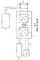
- the light source is a gas discharge lamp 5, which is controlled by an electric ballast (ECG) 1 as a control gear.
- ECG electric ballast
- this electronic ballast 1 has a rectifier with power factor correction circuit (PFC, Power Factor Correction) 2, an electrolyte storage capacitor 4 and an RF inverter 3, which in turn via its output circuit 6, the gas discharge lamp 5 drives.
- the DC voltage (bus voltage) is therefore only present within the ECG.
- an emergency lighting control 7 may be provided.
- the rectifier 2 in the electronic ballast 1 is usually supplied with alternating voltage 9, for example mains voltage.
- the invention assumes that the unit rectifier / PFC is no longer provided locally in each operating device, but centrally for several operating devices.
- the connection between this control center and the individual operating devices takes place via a DC output circuit.
- the object of the invention is to propose a control for light-emitting devices, which further allows a cost-effective production of operating devices, while ensuring a flexible and adapted to the needs of the connected equipment supply despite the central configuration.
- the central processing unit may further include a power factor correction (PFC) circuit.
- PFC power factor correction
- the output circuits with different DC voltage levels can be assigned operating devices for different types of light sources (for example gas discharge lamp, LED, etc.).
- the central unit can also have a pure digital signal output circuit, which therefore does not serve for the power supply.
- an operating device may be connected, which has a power supply independent of the central unit, in particular a mains AC power supply.
- One of the output circuits of the central unit may be connected to ground, wherein at least two further output circuits have DC voltage levels which are designed symmetrically around the ground potential.
- these two further output circuits can also be designed asymmetrically around the ground potential.
- At least one operating device may be connected to output circuits having different DC levels.
- An output circuit can serve, for example, for the provision of the lamp operating power and at least one further output circuit for the provision of a low-voltage power supply of logic components in a control gear.
- At least one of the operating devices may be an electronic ballast (ECG) for gas discharge lamps, which is an inverter having.
- ECG electronic ballast
- the operating device may also be referred to as output converter.
- drive signals can be transmitted via at least one of the output circuits in accordance with a powerline technique, these drive signals thus being modulated onto the DC voltage.
- An operating device associated with a light source can be switched off by transmitting a Ausscibilsberioses via one of the output circuits, the power supply can be maintained unchanged via a further output circuit.
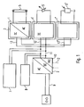
- a central unit comprising, for example, a rectifier 2 and optionally also a power factor correction circuit (PFC) 10, is jointly provided for a plurality of lamp operating devices 1, 1 ', 1 "
- the central unit 2, 10 can also be spatially separated from the operating devices and, for example, be arranged centrally for a room, a floor or even a building in a control cabinet, etc.
- the various light-emitting devices operating devices 1, 1 ', 1 a variety of light sources, such as a gas discharge lamp 5, light emitting diodes 5', etc. Actuate the bulbs themselves can be operated with DC or AC voltage, wherein in the latter case, an inverter is provided in the associated operating device.
- a light sensor 5 or a motion detector (not shown) may be connected to a DC output circuit 11 of the central unit.
- the operating devices 1, 1', 1" are designed differently.
- the corresponding operating device 3 is, for example, as an electronic ballast (EVG) u.a. formed with an inverter.
- EDG electronic ballast
- the operating devices can also be referred to as "output converters".
- an output circuit 11 can be configured in a bus-like manner, so that the various operating devices 1, 1 ', 1 "are supplied via stubs 13, 13', 13 'starting from this central common bus 11.
- individual operating devices can be supplied or jointly supplied groups of operating devices individual output circuits 12 may be provided.
- This DC output circuit has the advantage of being less susceptible to parasitic effects than corresponding AC circuits.
- the central unit is provided for a plurality of operating devices in common, wherein the central unit is connected to the operating devices by means of at least one DC output circuit.
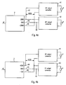
- Fig. 3 shows an embodiment of the invention, in which the central unit 2 controls a total of three output circuits with different DC levels, namely a first output circuit 31 with a high-voltage DC voltage of, for example, 400 volts, a second output circuit 32 with a low-voltage DC voltage of 12 volts, for example, and another Output circuit 33, which is connected to ground.
- a first output circuit 31 with a high-voltage DC voltage of, for example, 400 volts
- a second output circuit 32 with a low-voltage DC voltage of 12 volts, for example
- another Output circuit 33 which is connected to ground.
- the low-voltage output circuit 32 can serve for the supply of logic components in the operating devices 3 or also for signal transmission, for example, by being designed as a digital bus. Alternatively, in the sense of a powerline technique, this 12 volt high-frequency drive signals can be modulated on.
- the low-voltage output circuit 32 and the operating devices 2 respectively associated lighting means can be turned off, as shown schematically by a switch 36.
- a switch 36 The fact that the switching off (indirectly) via the low-voltage output circuit 32 and not (directly) via the high-voltage output circuit 31, the problem of the spark gap is significantly reduced when the switch 36 is open. If, for example, the low-voltage output circuit 32 supplies the logic components in the operating device 3 via the respective terminal 35, by opening the switch 36, these corresponding logic components, for example the control of the inverter in an electronic ballast can be switched off, which in turn causes the associated gas discharge lamp 5 to go out leads.
- the mechanical switch 36 can be replaced at any time by a transmission of corresponding digital commands transmitted via the low voltage output circuit 32 and read at the input 35 of the operating device, for example by a powerline demodulator (not shown) and in a Control command for a local control unit to be implemented in a control gear.
- bulbs can naturally also be switched off, for example by the central unit 2 being switched off altogether by an upstream mains switch 37.
- the low-voltage output circuit with, for example, 12 V DC can be used in any combination as power supply for light sources (in particular for LEDs), as supply voltage for logic components (eg ASICs) in an operating device and / or as a control circuit.
- FIG. 4 shows Fig. 4 an embodiment in which the voltage levels of the output circuits of the central unit 2 are designed such that by appropriate combination at the terminals of the operating devices this optionally with a high DC voltage HV, a medium DC voltage MV and a low DC voltage LV supplies can be.
- operating devices to which different types of lamps are connected can be individually supplied according to their respective requirements for the power supply.
- a high DC voltage is suitable, for example, for gas discharge lamps, while a low DC voltage supply, for example, for LED bulbs offers.
- a high-voltage operating device 41 and a medium-voltage operating device 42 are shown, with 400 volts DC or 200th Voltage DC be supplied.
- the central unit 2 shown has a total of three output circuits 45, 47, 48, wherein one output circuit 45 is connected to ground (GND) and the other two output circuits 47, 48 voltage level symmetrical about this ground potential, here in the form of ⁇ 200 volts.
- GND ground
- the bulbs are shown purely schematically. Meanwhile, the bulbs can be of any nature and, for example, also be connected in groups in series and / or in parallel to an operating device.
- ballasts of all kinds can be operated with the 400V DC
- the average voltage of 200V DC for example, is suitable for simple electronic ballasts that provide low lamp burning voltages.
- Fig. 4b shows a modification of Fig. 4a to the effect that, although the central unit 2 further has a plurality of output circuits 44, 45, 46 with different DC potential, in addition to the ground output circuit 45 provided further output circuits 44, 46 but in this case lead levels that asymmetric to said ground potential, here in the form of +400 volts DC and -12 volts DC, respectively.
- a high-voltage DC supply for an operating device 41 or a low-voltage DC supply for an operating device 43 can be achieved.
- the low-voltage DC supply for example, 12 volts is particularly suitable for LED bulbs.
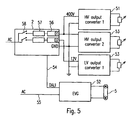
- Fig. 5 now shows a modification of the aforementioned embodiments in that in addition to the output circuits that ensure a power supply, possibly in combination with a powerline signal transmission, the central unit 2 is a pure control output circuit 54, for example, according to the DALI (Digital Addressable Lighting Interface) standard.
- This control output circuit 54 thus does not supply the associated operating means, here an electronic ballast 52 with the operating voltage. Rather, in the sense of a well-known from the prior art electronic ballast with digital interface of this electronic ballast 52 is supplied independently of the central unit 2 with mains voltage 55 to drive the gas discharge lamp 5.
- the central unit may comprise a plurality of parallel modules, each having a PFC 57 and an electronic fuse 56. Each module is assigned a live output circuit. In particular, different modules can supply output circuits with different DC voltage levels.
- a switch 58 is connected upstream of each module so that modules can be switched on or off individually in order to switch the respectively assigned output circuits.
- certain operating devices or groups thereof and the associated bulbs can be selectively switched on and off.
Description
Die vorliegende Erfindung bezieht sich auf ein System mit den Merkmalen des Oberbegriffes des Anspruches 1. Ein solches System ist nach der
Ebenfalls bekannt ist das in
Zusätzlich kann eine Notbeleuchtungssteuerung 7 vorgesehen sein.In addition, an emergency lighting control 7 may be provided.
Der Gleichrichter 2 in dem EVG 1 wird üblicherweise mit Wechselspannung 9, beispielsweise Netzspannung, versorgt.The
Gleichzeitig ist es bekannt, das EVG 1 über eine Digitaloder Analogbussteuerung 8 anzusteuern, um somit die Lampe 5 zu starten, zu dimmen oder auszuschalten. Festzuhalten ist, dass bei diesem Stand der Technik in jedem Lampenbetriebsgerät (EVG 1) ein eigener Gleichrichter 2 mit PFC-Schaltung vorgesehen ist. Eine derartige PFC-Schaltung verringert bekanntlich störende Oberwellen im Eingangsstrom. Andererseits stellen diese lokal in jedem EVG 1 vorgesehenen Wechselrichter mit PFC 2 einen beträchtlichen Kostenfaktor dar, der den Trend zu äußerst kostengünstig gefertigten EVG's stark eingrenzt.At the same time, it is known to control the
>>
Die Erfindung geht davon aus, dass die Einheit Gleichrichter/PFC nicht mehr lokal in jedem Betriebsgerät, sondern zentral für mehrere Betriebsgeräte vorgesehen ist. Die Verbindung zwischen dieser Zentrale und den einzelnen Betriebsgeräten erfolgt über einen DC-Ausgangskreis.The invention assumes that the unit rectifier / PFC is no longer provided locally in each operating device, but centrally for several operating devices. The connection between this control center and the individual operating devices takes place via a DC output circuit.
Aufgabe der Erfindung ist es, eine Ansteuerung für Leuchtmittel-Betriebsgeräte vorzuschlagen, die weiterhin eine kostengünstige Fertigung von Betriebsgeräten ermöglicht, dabei aber trotz der zentralen Ausgestaltung eine flexible und auf die Bedürfnisse der angeschlossenen Betriebsgeräte angepasste Versorgung gewährleistet.The object of the invention is to propose a control for light-emitting devices, which further allows a cost-effective production of operating devices, while ensuring a flexible and adapted to the needs of the connected equipment supply despite the central configuration.
Die Aufgabe ist durch die im Kennzeichen des Anspruchs 1 angegebenen Merkmale gelöst.The object is solved by the features specified in the characterizing part of
In diesem Zusammenhang ist zu bemerken, dass nach der
Die Zentraleinheit kann weiterhin eine Leistungsfaktor-Korrekturschaltung (PFC-)Schaltung aufweisen.The central processing unit may further include a power factor correction (PFC) circuit.
Den Ausgangskreisen mit unterschiedlichen Gleichspannungspegeln können Betriebsgeräte für unterschiedliche Typen an Leuchtmitteln (beispielsweise Gasentladungslampe, LED, etc.) zugeordnet sein.The output circuits with different DC voltage levels can be assigned operating devices for different types of light sources (for example gas discharge lamp, LED, etc.).
Die Zentraleinheit kann zusätzlich auch einen reinen Digitalsignal-Ausangskreis aufweisen, der also nicht zur Leistungsversorgung dient.In addition, the central unit can also have a pure digital signal output circuit, which therefore does not serve for the power supply.
Mit dem Digitalsignal-Ausgangskreis kann ein Betriebsgerät verbunden sein, das eine von der Zentraleinheit unabhängige Spannungsversorgung, insbesondere eine Netz-Wechselspannungsversorgung aufweist.With the digital signal output circuit, an operating device may be connected, which has a power supply independent of the central unit, in particular a mains AC power supply.
Einer der Ausgangskreise der Zentraleinheit kann mit Masse verbunden sein, wobei wenigstens zwei weitere Ausgangskreise Gleichspannungspegel aufweisen, die um das Massepotential herum symmetrisch ausgelegt sind.One of the output circuits of the central unit may be connected to ground, wherein at least two further output circuits have DC voltage levels which are designed symmetrically around the ground potential.
Alternativ können diese beiden weiteren Ausgangskreise auch asymmetrisch um das Massepotential herum ausgelegt sein.Alternatively, these two further output circuits can also be designed asymmetrically around the ground potential.
Wenigstens ein Betriebsgerät kann mit Ausgangskreisen mit unterschiedlichen Gleichspannungspegeln verbunden sein.At least one operating device may be connected to output circuits having different DC levels.
Ein Ausgangskreis kann dabei beispielsweise für die Bereitstellung der Leuchtmittel-Betriebsleistung und wenigstens ein weiterer Ausgangskreis für die Bereitstellung einer Niedervolt-Spannungsversorgung von Logikbauteilen in einem Betriebsgerät dienen.An output circuit can serve, for example, for the provision of the lamp operating power and at least one further output circuit for the provision of a low-voltage power supply of logic components in a control gear.
Wenigstens eines der Betriebsgeräte kann ein elektronisches Vorschaltgerät (EVG) für Gasentladungslampen sein, das einen Wechselrichter aufweist. In diesem Fall kann das Betriebsgerät auch als Ausgangs-Konverter bezeichnet werden.At least one of the operating devices may be an electronic ballast (ECG) for gas discharge lamps, which is an inverter having. In this case, the operating device may also be referred to as output converter.
Über wenigstens einen der Ausgangskreise können Ansteuersignale beispielsweise gemäß einer Powerline-Technik übermittelt werden, wobei diese Ansteuersignale also der Gleichspannung aufmoduliert sind.By way of example, drive signals can be transmitted via at least one of the output circuits in accordance with a powerline technique, these drive signals thus being modulated onto the DC voltage.
In der Zentraleinheit selbst können für Ausgangskreise mit unterschiedlichen Gleichspannungspegeln unterschiedliche Gleichrichter- und/oder PFC-Module vorgesehen sein.In the central unit itself, different rectifier and / or PFC modules can be provided for output circuits with different DC voltage levels.
Ein einem Betriebsgerät zugeordnetes Leuchtmittel kann durch Übertragung eines Ausschaltbefehles über einen der Ausgangskreise ausschaltbar sein, wobei die Spannungsversorgung über einen weiteren Ausgangskreis unverändert beibehalten werden kann.An operating device associated with a light source can be switched off by transmitting a Ausschaltungsbefehles via one of the output circuits, the power supply can be maintained unchanged via a further output circuit.
Weitere Merkmale, Vorteile und Eigenschaften der vorliegenden Erfindung sollen nunmehr unter Bezugnahme auf die Figuren der beigefügten Zeichnungen sowie die folgende detaillierte Beschreibung eines Ausführungsbeispieles näher erläutert werden.
- Fig. 1
- zeigt eine schematische Ansicht eines erfindungsgemäßen Steuersystems für Leuchtmittel-Betriebsgeräte mit zentraler Gleichrichter/PFC-Einheit und DC-Ausgangskreis,
- Fig. 2
- zeigt eine aus dem Stand der Technik bekannte Betriebsmittel-Ausgestaltung für Gasentladungslampen,
- Fig. 3
- zeigt ein Ausführungsbeispiel der vorliegenden Erfindung, bei dem Betriebsgeräte für Leuchtmittel mit der Zentraleinheit jeweils über Ausgangskreise mit unterschiedlichen Gleichspannungspegeln verbunden sind,
- Fig. 4a
- zeigt ein Ausführungsbeispiel der vorliegenden Erfindung, bei dem die Betriebsgeräte mit der Zentraleinheit über mehrere Ausgangskreise verbunden sind, wobei DC-Spannungspegel von wenigstens zwei Ausgangskreisen symmetrisch um das Massepotential herum ausgelegt sind,
- Fig. 4b
- zeigt ein Abwandlung des Ausführungsbeispiels von
Fig. 4a dahingehend, dass zwei Ausgangskreise Gleichspannungspegel aufweisen, die um das Massepotential herum asymmetrisch ausgelegt sind, und - Fig. 5
- zeigt ein weiteres Ausführungsbeispiel der vorliegenden Erfindung, bei dem die Zentraleinheit einen reinen Steuerausgang aufweist, der ein Betriebsgerät ansteuert, das seine Betriebsspannungsversorgung unabhängig von der Zentraleinheit ausgelegt hat.
- Fig. 1
- shows a schematic view of a control system according to the invention for light-emitting devices with central rectifier / PFC unit and DC output circuit,
- Fig. 2
- shows a known from the prior art equipment design for gas discharge lamps,
- Fig. 3
- shows an embodiment of the present invention, in which operating devices for lamps are connected to the central unit via output circuits with different DC levels,
- Fig. 4a
- shows an embodiment of the present invention in which the operating devices are connected to the central unit via a plurality of output circuits, wherein DC voltage levels of at least two output circuits are designed symmetrically around the ground potential,
- Fig. 4b
- shows a modification of the embodiment of
Fig. 4a in that two output circuits have DC voltage levels that are asymmetrically designed around the ground potential, and - Fig. 5
- shows a further embodiment of the present invention, in which the central unit has a pure control output, which drives a control device, which has designed its operating voltage supply independently of the central unit.
Wie in
Wie in
Weiterhin können an einen DC-Ausgangskreis 11 der Zentraleinheit auch andere (bspw. passive) lichttechnische oder gebäudetechnische Einrichtungen, wie beispielsweise ein Lichtsensor 5" oder ein Bewegungsmelder (nicht dargestellt) angeschlossen sein.Furthermore, other (eg passive) lighting or building services equipment, such as a
Je nach Natur der angeschlossenen Leuchtmittel 5, 5' bzw. Sensoren 5" sind die Betriebsgeräte 1, 1', 1" unterschiedlich ausgebildet. Für den Fall, dass eine Gasentladungslampe 5 angesteuert werden soll, ist das entsprechende Betriebsgerät 3 bspw. als elektronisches Vorschaltgerät (EVG) u.a. mit einem Wechselrichter ausgebildet. Die Betriebsgeräte können in diesem Fall auch als "Ausgangs-Konverter" bezeichnet werden.Depending on the nature of the
Die Spannungsversorgung der Betriebsgeräte und Leuchtmittel und optional auch die uni- oder bidirektionale Kommunikation zwischen der Zentraleinheit und den lokalen Betriebsgeräten 1, 1', 1" erfolgt über wenigstens einen DC-Ausgangskreis 11, 12. Wie in
Dieser DC-Ausgangskreis hat den Vorteil, dass er im Vergleich zu entsprechenden AC-Kreisen weniger anfällig gegenüber parasitären Effekten ist.This DC output circuit has the advantage of being less susceptible to parasitic effects than corresponding AC circuits.
Festzuhalten ist, dass gemäß der vorliegenden Erfindung die Zentraleinheit für mehrere Betriebsgeräte gemeinsam vorgesehen ist, wobei die Zentraleinheit mit den Betriebsgeräten mittels wenigstens einem DC-Ausgangskreis verbunden ist.It should be noted that according to the present invention, the central unit is provided for a plurality of operating devices in common, wherein the central unit is connected to the operating devices by means of at least one DC output circuit.
Die beiden in
Schließlich kann über den Niedervolt-Ausgangskreis 32 auch das den Betriebsgeräten 2 jeweils zugeordnete Leuchtmittel ausgeschaltet werden, wie schematisch durch einen Schalter 36 dargestellt ist. Dadurch, dass das Ausschalten (indirekt) über den Niederspannungs-Ausgangskreis 32 und nicht (direkt) über den Hochspannungs-Ausgangskreis 31 erfolgt, wird das Problem der Funkenstrecke bei geöffnetem Schalter 36 deutlich verringert. Falls also beispielsweise der Niederspannungs-Ausgangskreis 32 die Logikbauteile in dem Betriebsgerät 3 über den jeweiligen Anschluß 35 versorgt, können durch Öffnen des Schalters 36 diese entsprechenden Logikbauteile, beispielsweise die Ansteuerung des Wechselrichters in einem EVG abgeschaltet werden, was wiederum zum Verlöschen der zugeordneten Gasentladungslampe 5 führt.Finally, via the low-
Auch wenn somit das zugeordnete Leuchtmittel, hier die Gasentladungslampen 5, abgeschaltet werden, steht nach wie vor die Betriebsspannung von 400 Volt über den Ausgangskreis 31 zur Verfügung, so dass die entsprechenden Leuchtmittel ausgehend von diesem Standby-Betrieb jederzeit wieder schnell eingeschaltet werden, indem beispielsweise der Schalter 36 wieder geschlossen wird. Es ist anzumerken, dass der mechanische Schalter 36 jederzeit durch eine Übermittlung von entsprechenden Digitalbefehle ersetzt werden kann, die über den Niederspannungs-Ausgangskreis 32 übermittelt werden und am Eingang 35 des Betriebsgeräts beispielsweise durch einen Powerline-Demodulator (nicht dargestellt) ausgelesen und in einen Ansteuerbefehl für eine lokale Steuereinheit in einem Betriebsgerät umgesetzt werden.Even if, therefore, the associated light source, here the
Alternativ können Leuchtmittel natürlich auch abgeschaltet werden, indem bspw. durch einen vorgeschalteten Netzschalter 37 die Zentraleinheit 2 insgesamt abgeschaltet wird.Alternatively, bulbs can naturally also be switched off, for example by the
Allgemein kann der Niedervolt-Ausgangskreis mit bspw. 12V DC in beliebiger Kombination als Spannungsversorgung für Leuchtmittel (insbesondere für LEDs), als Versorgungsspannung für Logikbauteile (bspw. ASICs) in einem Betriebsgerät und/oder als Steuerkreis verwendet werden.In general, the low-voltage output circuit with, for example, 12 V DC can be used in any combination as power supply for light sources (in particular for LEDs), as supply voltage for logic components (eg ASICs) in an operating device and / or as a control circuit.
Während bei dem Ausführungsbeispiel gemäß
Somit können Betriebsgeräte, an die unterschiedliche Typen an Leuchtmitteln angeschlossen sind, individuell entsprechend ihren jeweiligen Anforderungen an die Spannungsversorgung versorgt werden. Eine hohe DC-Spannung bietet sich beispielsweise für Gasentladungslampen an, während sich eine niedrige Gleichspannungsversorgung beispielsweise für LED-Leuchtmittel anbietet.Thus, operating devices to which different types of lamps are connected, can be individually supplied according to their respective requirements for the power supply. A high DC voltage is suitable, for example, for gas discharge lamps, while a low DC voltage supply, for example, for LED bulbs offers.
In dem Ausführungsbeispiel von
Während bspw. EVGs aller Art mit den 400V DC betrieben werden können., ist die mittlere Spannung von 200V DC bspw. für einfache EVGs geeignet, die niedrige Lampen-Brennspannungen bereitstellen.While, for example, electronic ballasts of all kinds can be operated with the 400V DC, the average voltage of 200V DC, for example, is suitable for simple electronic ballasts that provide low lamp burning voltages.
Die Zentraleinheit kann aus mehreren parallelen Modulen aufweisend jeweils einen PFC 57 und eine elektronische Sicherung 56 aufweisen. Jedem Modul ist dabei ein spannungsführender Ausgangskreis zugeordnet. Insbesondere können unterschiedliche Module Ausgangskreise mit unterschiedlichen DC-Spannungspegeln versorgen.The central unit may comprise a plurality of parallel modules, each having a
Bei einem derartigen modularen Aufbau kann vorgesehen sein, dass jedem Modul ein Schalter 58 vorgeschaltet ist, so dass Module individuell ein- oder ausgeschaltet werden können, um somit die jeweils zugeordneten Ausgangskreise zu schalten. Somit können bestimmte Betriebsgeräte bzw. Gruppen davon sowie die zugehörigen Leuchtmittel gezielt ein- und ausgeschaltet werden.With such a modular design, it can be provided that a
Claims (14)
- System for actuating operating devices for luminous means, having:a central unit (2), which has a rectifier circuit and can be supplied with AC voltage, a plurality of operating devices (1, 1', 1"; 3; 41, 42; 51-53) each of which is assigned at least one luminous means, and a first DC output circuit (11; 31, 33; 45-47), originating from the central unit (2), for supplying operating devices with a first DC voltage level,characterized
in that at least one second DC output circuit (12; 31, 32, 33; 45-47) having a second DC voltage level which is different from the first DC voltage level originates from the central unit (2), wherein the second DC output circuit alternatively or additionally supplies individual operating devices or jointly supplied groups of operating devices with a second DC voltage level which is different from the first DC voltage level. - System according to Claim 1,
characterized
in that the central unit (2) also has a power factor correction circuit (10) (figure 1). - System according to either of the preceding claims,
characterized
in that operating devices (1, 1', 1") for different luminous means (5, 5', 5") are assigned to output circuits (11, 13, 13', 13"; 12) having different DC voltage levels (figure 1). - System according to one of the preceding claims,
characterized
in that the central unit (2) also has a pure digital signal output circuit (54) (figure 5). - System according to Claim 4,
characterized
in that an operating device (52) is connected to the digital signal output circuit (54), said operating device having a voltage supply which is independent of the central unit (2), in particular an AC voltage supply (figure 5). - System according to one of the preceding claims,
characterized
in that one of the output circuits (45) of the central unit (2) is connected to earth and at least two further output circuits (47, 48) have DC voltage levels which are symmetrical with respect to the earth potential (figure 4a). - System according to one of the preceding claims,
characterized
in that one of the output circuits (45) of the central unit (2) is connected to earth and at least two further output circuits (44, 46) have DC voltage levels which are asymmetrical with respect to the earth potential (figure 4b). - System according to one of the preceding claims,
characterized
in that at least one operating device (41) is connected to output circuits (44, 46) having different DC voltage levels (figure 4b). - System according to one of the preceding claims,
characterized
in that at least one output circuit (31, 33) is used to provide the luminous means operating power and at least one further output circuit (32) is used to provide a low-voltage supply for logic components in an operating device (3) (figure 3). - System according to one of the preceding claims,
characterized
in that at least one of the operating devices (3) is an electronic ballast for gas discharge lamps (5), said ballast having an inverter (figures 1 and 3). - System according to one of the preceding claims,
characterized
in that actuation signals are transmitted via at least one of the output circuits (32), said actuation signals being modulated onto the DC voltage (figure 3). - System according to one of the preceding claims,
characterized
in that different modules (57) are provided in the central unit (2) for output circuits having different DC voltage levels (figure 5). - System according to one of the preceding claims,
characterized
in that a luminous means (5) associated with an operating device can be switched off as a result of the transmission of a switch-off command via an output circuit (32), wherein the voltage supply is maintained by means of a further output circuit (31, 33) (figure 3). - System according to one of the preceding claims,
characterized
in that an operating device (3) can be switched off by means of a switch (36) in a low-voltage output circuit (32) (figure 3).
Priority Applications (1)
| Application Number | Priority Date | Filing Date | Title |
|---|---|---|---|
| EP10182653.5A EP2278861B1 (en) | 2004-01-14 | 2004-11-26 | Central power supply having several DC output circuits |
Applications Claiming Priority (2)
| Application Number | Priority Date | Filing Date | Title |
|---|---|---|---|
| DE102004002016A DE102004002016A1 (en) | 2004-01-14 | 2004-01-14 | Central supply via several DC output circuits |
| DE102004002016 | 2004-01-14 |
Related Child Applications (1)
| Application Number | Title | Priority Date | Filing Date |
|---|---|---|---|
| EP10182653.5 Division-Into | 2010-09-29 |
Publications (2)
| Publication Number | Publication Date |
|---|---|
| EP1555857A1 EP1555857A1 (en) | 2005-07-20 |
| EP1555857B1 true EP1555857B1 (en) | 2013-10-02 |
Family
ID=34609548
Family Applications (2)
| Application Number | Title | Priority Date | Filing Date |
|---|---|---|---|
| EP10182653.5A Active EP2278861B1 (en) | 2004-01-14 | 2004-11-26 | Central power supply having several DC output circuits |
| EP04028165.1A Active EP1555857B1 (en) | 2004-01-14 | 2004-11-26 | Central power supply having several DC output circuits |
Family Applications Before (1)
| Application Number | Title | Priority Date | Filing Date |
|---|---|---|---|
| EP10182653.5A Active EP2278861B1 (en) | 2004-01-14 | 2004-11-26 | Central power supply having several DC output circuits |
Country Status (3)
| Country | Link |
|---|---|
| EP (2) | EP2278861B1 (en) |
| DE (1) | DE102004002016A1 (en) |
| HK (1) | HK1148161A1 (en) |
Families Citing this family (6)
| Publication number | Priority date | Publication date | Assignee | Title |
|---|---|---|---|---|
| DE102006035046B4 (en) * | 2006-07-28 | 2013-05-29 | Insta Elektro Gmbh | Electric / electronic central unit |
| JP2009158298A (en) * | 2007-12-26 | 2009-07-16 | Panasonic Electric Works Co Ltd | Hook ceiling |
| DE102009054371A1 (en) | 2009-11-17 | 2011-06-22 | Automotive Lighting Reutlingen GmbH, 72762 | Control device for controlling a lighting device of a motor vehicle, as well as lighting device for a motor vehicle with such a control device |
| DE102010031244B4 (en) | 2010-03-19 | 2023-01-12 | Tridonic Ag | Modular LED lighting system |
| WO2013040736A1 (en) * | 2011-09-19 | 2013-03-28 | 东莞勤上光电股份有限公司 | Dc high voltage power supply led street lamp system and realization method thereof |
| WO2014174159A1 (en) | 2013-04-24 | 2014-10-30 | Societe D'etudes Et D'economies En Eclairage, Se3 | Device for supplying direct current for a set of led-based lighting devices used in industrial lighting and tertiary lighting |
Citations (2)
| Publication number | Priority date | Publication date | Assignee | Title |
|---|---|---|---|---|
| EP1244337A1 (en) * | 2001-03-20 | 2002-09-25 | MAGNETEK S.p.A. | Lighting system with an electrified line and a plurality of lighting fixtures connected to it |
| WO2003067934A2 (en) * | 2002-02-06 | 2003-08-14 | Color Kinetics Incorporated | Controlled lighting methods and apparatus |
Family Cites Families (7)
| Publication number | Priority date | Publication date | Assignee | Title |
|---|---|---|---|---|
| GB943241A (en) * | 1960-11-23 | 1963-12-04 | Marconi Instruments Ltd | Improvements in or relating to rectifier circuit arrangements |
| US4626697A (en) * | 1984-10-22 | 1986-12-02 | American Hospital Supply Corporation | Power supply for providing plural DC voltages |
| AU6908894A (en) * | 1993-05-13 | 1994-12-12 | Etta Industries, Inc. | System and method for distributing power to gas discharge lamps |
| DE29622825U1 (en) * | 1996-03-29 | 1997-07-10 | Lohmann Werke Gmbh & Co | Radiation device |
| IT1316561B1 (en) * | 2000-12-28 | 2003-04-22 | Setech S R L | FEEDING DEVICE FOR COLD CATHODE LAMPS. |
| US6771029B2 (en) * | 2001-03-28 | 2004-08-03 | International Rectifier Corporation | Digital dimming fluorescent ballast |
| US20030036807A1 (en) * | 2001-08-14 | 2003-02-20 | Fosler Ross M. | Multiple master digital addressable lighting interface (DALI) system, method and apparatus |
-
2004
- 2004-01-14 DE DE102004002016A patent/DE102004002016A1/en not_active Ceased
- 2004-11-26 EP EP10182653.5A patent/EP2278861B1/en active Active
- 2004-11-26 EP EP04028165.1A patent/EP1555857B1/en active Active
-
2011
- 2011-03-03 HK HK11102139.5A patent/HK1148161A1/en not_active IP Right Cessation
Patent Citations (2)
| Publication number | Priority date | Publication date | Assignee | Title |
|---|---|---|---|---|
| EP1244337A1 (en) * | 2001-03-20 | 2002-09-25 | MAGNETEK S.p.A. | Lighting system with an electrified line and a plurality of lighting fixtures connected to it |
| WO2003067934A2 (en) * | 2002-02-06 | 2003-08-14 | Color Kinetics Incorporated | Controlled lighting methods and apparatus |
Also Published As
| Publication number | Publication date |
|---|---|
| DE102004002016A1 (en) | 2005-08-04 |
| EP2278861B1 (en) | 2013-09-18 |
| EP2278861A1 (en) | 2011-01-26 |
| HK1148161A1 (en) | 2011-08-26 |
| EP1555857A1 (en) | 2005-07-20 |
Similar Documents
| Publication | Publication Date | Title |
|---|---|---|
| EP1555859B1 (en) | Control of lighting devices over a modulated DC bus | |
| EP2676531B1 (en) | Combined sensor/emergency light unit for a lighting system | |
| DE10344619B4 (en) | Control system for a plurality of distributed lamp operating devices and method for initializing such a control system | |
| EP1619935B1 (en) | Emergency lighting power supply unit with digital addressable control interface | |
| EP1947913B1 (en) | DC supplied operating module for illuminant | |
| DE19502772C2 (en) | Electronic ballast for fluorescent lamps | |
| EP1555857B1 (en) | Central power supply having several DC output circuits | |
| EP1583402B1 (en) | Control of lighting devices with a central AC/DC cascaded converter | |
| EP1555861B1 (en) | Control of lighting apparatusses through switching modulation on a DC-bus | |
| EP2582545B1 (en) | Emergency lighting for railway vehicle | |
| EP0903966B1 (en) | Lighting system | |
| EP2365737B1 (en) | Central PFC with DC output circuit regulation | |
| EP1271745B1 (en) | Method for operation of an electric end-user as well as a device using such a method | |
| DE112011100717B4 (en) | Operating device for lamps and bus system and method for operating a control gear | |
| EP2182778A1 (en) | Method for controlling an external light and corresponding lamps | |
| DE102004012216B4 (en) | Control of illuminant control gear via a switchable DC bus | |
| DE102009051738A1 (en) | Emergency lighting device with LED | |
| EP0978924A2 (en) | Electrical installation for mains and stand-by power supply of safety lights | |
| WO2011038438A1 (en) | Interface for an operating device for a lighting means | |
| DE102005059612A1 (en) | Switch device for street lighting with an all-night circuit has safety fuses and a three-way switch relay to ensure power supply always connects to the same contact during alternate operation | |
| DE102014111711A1 (en) | Control of power consumption of outdoor electrical consumers | |
| DE202012012473U1 (en) | Device for controlling a fluorescent lamp |
Legal Events
| Date | Code | Title | Description |
|---|---|---|---|
| PUAI | Public reference made under article 153(3) epc to a published international application that has entered the european phase |
Free format text: ORIGINAL CODE: 0009012 |
|
| AK | Designated contracting states |
Kind code of ref document: A1 Designated state(s): AT BE BG CH CY CZ DE DK EE ES FI FR GB GR HU IE IS IT LI LU MC NL PL PT RO SE SI SK TR |
|
| AX | Request for extension of the european patent |
Extension state: AL HR LT LV MK YU |
|
| 17P | Request for examination filed |
Effective date: 20050927 |
|
| AKX | Designation fees paid |
Designated state(s): AT BE BG CH CY CZ DE DK EE ES FI FR GB GR HU IE IS IT LI LU MC NL PL PT RO SE SI SK TR |
|
| 17Q | First examination report despatched |
Effective date: 20070125 |
|
| RAP1 | Party data changed (applicant data changed or rights of an application transferred) |
Owner name: TRIDONIC GMBH & CO KG |
|
| RIC1 | Information provided on ipc code assigned before grant |
Ipc: H05B 41/24 20060101ALN20130228BHEP Ipc: H05B 37/02 20060101AFI20130228BHEP |
|
| GRAP | Despatch of communication of intention to grant a patent |
Free format text: ORIGINAL CODE: EPIDOSNIGR1 |
|
| INTG | Intention to grant announced |
Effective date: 20130422 |
|
| GRAS | Grant fee paid |
Free format text: ORIGINAL CODE: EPIDOSNIGR3 |
|
| GRAA | (expected) grant |
Free format text: ORIGINAL CODE: 0009210 |
|
| AK | Designated contracting states |
Kind code of ref document: B1 Designated state(s): AT BE BG CH CY CZ DE DK EE ES FI FR GB GR HU IE IS IT LI LU MC NL PL PT RO SE SI SK TR |
|
| REG | Reference to a national code |
Ref country code: GB Ref legal event code: FG4D Free format text: NOT ENGLISH |
|
| REG | Reference to a national code |
Ref country code: CH Ref legal event code: EP Ref country code: AT Ref legal event code: REF Ref document number: 635152 Country of ref document: AT Kind code of ref document: T Effective date: 20131015 |
|
| REG | Reference to a national code |
Ref country code: IE Ref legal event code: FG4D Free format text: LANGUAGE OF EP DOCUMENT: GERMAN |
|
| REG | Reference to a national code |
Ref country code: DE Ref legal event code: R096 Ref document number: 502004014379 Country of ref document: DE Effective date: 20131128 |
|
| REG | Reference to a national code |
Ref country code: NL Ref legal event code: VDEP Effective date: 20131002 |
|
| PG25 | Lapsed in a contracting state [announced via postgrant information from national office to epo] |
Ref country code: SI Free format text: LAPSE BECAUSE OF FAILURE TO SUBMIT A TRANSLATION OF THE DESCRIPTION OR TO PAY THE FEE WITHIN THE PRESCRIBED TIME-LIMIT Effective date: 20131002 |
|
| PG25 | Lapsed in a contracting state [announced via postgrant information from national office to epo] |
Ref country code: CZ Free format text: LAPSE BECAUSE OF FAILURE TO SUBMIT A TRANSLATION OF THE DESCRIPTION OR TO PAY THE FEE WITHIN THE PRESCRIBED TIME-LIMIT Effective date: 20131002 Ref country code: FI Free format text: LAPSE BECAUSE OF FAILURE TO SUBMIT A TRANSLATION OF THE DESCRIPTION OR TO PAY THE FEE WITHIN THE PRESCRIBED TIME-LIMIT Effective date: 20131002 Ref country code: IS Free format text: LAPSE BECAUSE OF FAILURE TO SUBMIT A TRANSLATION OF THE DESCRIPTION OR TO PAY THE FEE WITHIN THE PRESCRIBED TIME-LIMIT Effective date: 20140202 Ref country code: SE Free format text: LAPSE BECAUSE OF FAILURE TO SUBMIT A TRANSLATION OF THE DESCRIPTION OR TO PAY THE FEE WITHIN THE PRESCRIBED TIME-LIMIT Effective date: 20131002 Ref country code: NL Free format text: LAPSE BECAUSE OF FAILURE TO SUBMIT A TRANSLATION OF THE DESCRIPTION OR TO PAY THE FEE WITHIN THE PRESCRIBED TIME-LIMIT Effective date: 20131002 |
|
| PG25 | Lapsed in a contracting state [announced via postgrant information from national office to epo] |
Ref country code: PL Free format text: LAPSE BECAUSE OF FAILURE TO SUBMIT A TRANSLATION OF THE DESCRIPTION OR TO PAY THE FEE WITHIN THE PRESCRIBED TIME-LIMIT Effective date: 20131002 Ref country code: CY Free format text: LAPSE BECAUSE OF FAILURE TO SUBMIT A TRANSLATION OF THE DESCRIPTION OR TO PAY THE FEE WITHIN THE PRESCRIBED TIME-LIMIT Effective date: 20131002 Ref country code: ES Free format text: LAPSE BECAUSE OF FAILURE TO SUBMIT A TRANSLATION OF THE DESCRIPTION OR TO PAY THE FEE WITHIN THE PRESCRIBED TIME-LIMIT Effective date: 20131002 |
|
| BERE | Be: lapsed |
Owner name: TRIDONIC GMBH & CO KG Effective date: 20131130 |
|
| PG25 | Lapsed in a contracting state [announced via postgrant information from national office to epo] |
Ref country code: PT Free format text: LAPSE BECAUSE OF FAILURE TO SUBMIT A TRANSLATION OF THE DESCRIPTION OR TO PAY THE FEE WITHIN THE PRESCRIBED TIME-LIMIT Effective date: 20140203 |
|
| REG | Reference to a national code |
Ref country code: CH Ref legal event code: PL |
|
| REG | Reference to a national code |
Ref country code: DE Ref legal event code: R097 Ref document number: 502004014379 Country of ref document: DE |
|
| PG25 | Lapsed in a contracting state [announced via postgrant information from national office to epo] |
Ref country code: MC Free format text: LAPSE BECAUSE OF FAILURE TO SUBMIT A TRANSLATION OF THE DESCRIPTION OR TO PAY THE FEE WITHIN THE PRESCRIBED TIME-LIMIT Effective date: 20131002 Ref country code: CH Free format text: LAPSE BECAUSE OF NON-PAYMENT OF DUE FEES Effective date: 20131130 Ref country code: EE Free format text: LAPSE BECAUSE OF FAILURE TO SUBMIT A TRANSLATION OF THE DESCRIPTION OR TO PAY THE FEE WITHIN THE PRESCRIBED TIME-LIMIT Effective date: 20131002 Ref country code: LI Free format text: LAPSE BECAUSE OF NON-PAYMENT OF DUE FEES Effective date: 20131130 |
|
| PLBE | No opposition filed within time limit |
Free format text: ORIGINAL CODE: 0009261 |
|
| STAA | Information on the status of an ep patent application or granted ep patent |
Free format text: STATUS: NO OPPOSITION FILED WITHIN TIME LIMIT |
|
| REG | Reference to a national code |
Ref country code: IE Ref legal event code: MM4A |
|
| PG25 | Lapsed in a contracting state [announced via postgrant information from national office to epo] |
Ref country code: SK Free format text: LAPSE BECAUSE OF FAILURE TO SUBMIT A TRANSLATION OF THE DESCRIPTION OR TO PAY THE FEE WITHIN THE PRESCRIBED TIME-LIMIT Effective date: 20131002 Ref country code: IT Free format text: LAPSE BECAUSE OF FAILURE TO SUBMIT A TRANSLATION OF THE DESCRIPTION OR TO PAY THE FEE WITHIN THE PRESCRIBED TIME-LIMIT Effective date: 20131002 Ref country code: RO Free format text: LAPSE BECAUSE OF FAILURE TO SUBMIT A TRANSLATION OF THE DESCRIPTION OR TO PAY THE FEE WITHIN THE PRESCRIBED TIME-LIMIT Effective date: 20131002 |
|
| 26N | No opposition filed |
Effective date: 20140703 |
|
| PG25 | Lapsed in a contracting state [announced via postgrant information from national office to epo] |
Ref country code: DK Free format text: LAPSE BECAUSE OF FAILURE TO SUBMIT A TRANSLATION OF THE DESCRIPTION OR TO PAY THE FEE WITHIN THE PRESCRIBED TIME-LIMIT Effective date: 20131002 Ref country code: BE Free format text: LAPSE BECAUSE OF NON-PAYMENT OF DUE FEES Effective date: 20131130 |
|
| REG | Reference to a national code |
Ref country code: DE Ref legal event code: R097 Ref document number: 502004014379 Country of ref document: DE Effective date: 20140703 |
|
| PG25 | Lapsed in a contracting state [announced via postgrant information from national office to epo] |
Ref country code: IE Free format text: LAPSE BECAUSE OF NON-PAYMENT OF DUE FEES Effective date: 20131126 |
|
| PG25 | Lapsed in a contracting state [announced via postgrant information from national office to epo] |
Ref country code: TR Free format text: LAPSE BECAUSE OF FAILURE TO SUBMIT A TRANSLATION OF THE DESCRIPTION OR TO PAY THE FEE WITHIN THE PRESCRIBED TIME-LIMIT Effective date: 20131002 |
|
| PG25 | Lapsed in a contracting state [announced via postgrant information from national office to epo] |
Ref country code: BG Free format text: LAPSE BECAUSE OF FAILURE TO SUBMIT A TRANSLATION OF THE DESCRIPTION OR TO PAY THE FEE WITHIN THE PRESCRIBED TIME-LIMIT Effective date: 20131002 Ref country code: HU Free format text: LAPSE BECAUSE OF FAILURE TO SUBMIT A TRANSLATION OF THE DESCRIPTION OR TO PAY THE FEE WITHIN THE PRESCRIBED TIME-LIMIT; INVALID AB INITIO Effective date: 20041126 Ref country code: LU Free format text: LAPSE BECAUSE OF NON-PAYMENT OF DUE FEES Effective date: 20131126 |
|
| PG25 | Lapsed in a contracting state [announced via postgrant information from national office to epo] |
Ref country code: GR Free format text: LAPSE BECAUSE OF NON-PAYMENT OF DUE FEES Effective date: 20131002 |
|
| REG | Reference to a national code |
Ref country code: FR Ref legal event code: PLFP Year of fee payment: 12 |
|
| PG25 | Lapsed in a contracting state [announced via postgrant information from national office to epo] |
Ref country code: GR Free format text: LAPSE BECAUSE OF FAILURE TO SUBMIT A TRANSLATION OF THE DESCRIPTION OR TO PAY THE FEE WITHIN THE PRESCRIBED TIME-LIMIT Effective date: 20140103 |
|
| REG | Reference to a national code |
Ref country code: FR Ref legal event code: PLFP Year of fee payment: 13 |
|
| PGFP | Annual fee paid to national office [announced via postgrant information from national office to epo] |
Ref country code: AT Payment date: 20161125 Year of fee payment: 13 |
|
| REG | Reference to a national code |
Ref country code: FR Ref legal event code: PLFP Year of fee payment: 14 |
|
| REG | Reference to a national code |
Ref country code: AT Ref legal event code: MM01 Ref document number: 635152 Country of ref document: AT Kind code of ref document: T Effective date: 20171126 |
|
| PG25 | Lapsed in a contracting state [announced via postgrant information from national office to epo] |
Ref country code: AT Free format text: LAPSE BECAUSE OF NON-PAYMENT OF DUE FEES Effective date: 20171126 |
|
| REG | Reference to a national code |
Ref country code: DE Ref legal event code: R084 Ref document number: 502004014379 Country of ref document: DE |
|
| PGFP | Annual fee paid to national office [announced via postgrant information from national office to epo] |
Ref country code: FR Payment date: 20191126 Year of fee payment: 16 |
|
| PGFP | Annual fee paid to national office [announced via postgrant information from national office to epo] |
Ref country code: GB Payment date: 20191128 Year of fee payment: 16 |
|
| GBPC | Gb: european patent ceased through non-payment of renewal fee |
Effective date: 20201126 |
|
| PG25 | Lapsed in a contracting state [announced via postgrant information from national office to epo] |
Ref country code: FR Free format text: LAPSE BECAUSE OF NON-PAYMENT OF DUE FEES Effective date: 20201130 |
|
| PG25 | Lapsed in a contracting state [announced via postgrant information from national office to epo] |
Ref country code: GB Free format text: LAPSE BECAUSE OF NON-PAYMENT OF DUE FEES Effective date: 20201126 |
|
| PGFP | Annual fee paid to national office [announced via postgrant information from national office to epo] |
Ref country code: DE Payment date: 20220527 Year of fee payment: 19 |
|
| P01 | Opt-out of the competence of the unified patent court (upc) registered |
Effective date: 20230530 |