EP1555806A2 - Graukomponentersetzung als Teil eines Steuerungsalgorithmus eines Markierverfahrens - Google Patents
Graukomponentersetzung als Teil eines Steuerungsalgorithmus eines Markierverfahrens Download PDFInfo
- Publication number
- EP1555806A2 EP1555806A2 EP05100207A EP05100207A EP1555806A2 EP 1555806 A2 EP1555806 A2 EP 1555806A2 EP 05100207 A EP05100207 A EP 05100207A EP 05100207 A EP05100207 A EP 05100207A EP 1555806 A2 EP1555806 A2 EP 1555806A2
- Authority
- EP
- European Patent Office
- Prior art keywords
- parameter
- color component
- color
- component
- threshold
- Prior art date
- Legal status (The legal status is an assumption and is not a legal conclusion. Google has not performed a legal analysis and makes no representation as to the accuracy of the status listed.)
- Ceased
Links
Images



Classifications
-
- H—ELECTRICITY
- H04—ELECTRIC COMMUNICATION TECHNIQUE
- H04N—PICTORIAL COMMUNICATION, e.g. TELEVISION
- H04N1/00—Scanning, transmission or reproduction of documents or the like, e.g. facsimile transmission; Details thereof
- H04N1/46—Colour picture communication systems
- H04N1/56—Processing of colour picture signals
- H04N1/60—Colour correction or control
- H04N1/6016—Conversion to subtractive colour signals
- H04N1/6022—Generating a fourth subtractive colour signal, e.g. under colour removal, black masking
Definitions
- the present invention is directed to a method for improving the effective total area coverage in a marking process, such as printing, photocopying or the like.
- Full color revision in digital images is an image processing operation which typically takes place in two steps.
- each pixel in the image is corrected from 3-D input device dependent (e.g., RGB) or device independent (e.g., YCrCb, R'G'B', XYZ, or L*a*b*) color space to a 3-D output device dependent color space (e.g., R"G"B" or CMY).
- CMYK e.g., CMY
- CMYK e.g., CMYK
- UCR under-color removal
- GCR gray-component replacement
- linearization processes Typically, the two color revision steps are accomplished in a single operation using a three-dimensional look-up table carrying out three-dimensional interpolation such as that described in U.S. Pat. No.
- the color revision portion of the process may also be represented as the combination of two phases: a 3-3 color space revision (e.g., RGB to R'G'B') followed by a device-dependent color space transformation operation (i.e., R'G'B' to CMYK for four color devices).
- a 3-3 color space revision e.g., RGB to R'G'B'
- a device-dependent color space transformation operation i.e., R'G'B' to CMYK for four color devices.
- GCR is used in the printing industry to reduce the amount of ink or other marking material deposition in a particular area, which enables faster drying times and lower ink usage and cost.
- some level of GCR is used to make shadow details more crisp by taking away some of the cyan, magenta, and yellow in equal amounts and replacing it with black.
- one component that drives development stability is throughput (i.e., the system or individual component output per unit of time).
- throughput i.e., the system or individual component output per unit of time.
- the marking system becomes unstable due to inadequate admix time of the developer components.
- very low area coverage large residence times of the toner or other marking material in the housing impact additives present in toner or other marking material, causing the toner or other marking material to lose its ability to hold a charge. Neither is desirable.
- Typical strategies for high area coverage include dead cycles where toner is added together with developer and mixed. Then printing is resumed. This solution results in reduced print speed, which is typically undesirable.
- the typical solution is to produce test patches which are developed on a photoreceptor, typically at inter-document zones, and taken away at a cleaner. This maintains a minimum throughput of a particular color to maintain stability.
- this solution typically results in higher costs because of unused toner that is thrown away to keep the marking system stable.
- This invention provides systems and methods that address the above-described problems by increasing and/or decreasing total area coverage for individual color components in a color marking environment for the purpose of maintaining developer stability.
- This invention separately provides systems, methods and structure that maintains a minimum throughput for each of a plurality of toner colors in a multicolor print engine by shifting and adjusting the ratio of multiple color material to black developed mass.
- This invention separately provides systems, methods and structure that provides gray component replacement in a multicolor print engine when individual colors are well below a desired minimum throughput to eliminate usage of such low throughput colors through shifting and adjusting ratios of other colors and black.
- images are provided by combining colors, such as cyan, magenta and yellow to form a process black.
- the systems and methods determine a color component with a very low coverage area that is below a threshold of development stability and provide one of 1) increasing area coverage of that color to achieve minimum throughput or 2) removing the very low coverage area of that color and replacing it with another color, such as black.
- increased coverage may be achieved by replacing portions of a black image with process black formed by a combination of cyan, magenta and yellow to increase throughput of a low coverage area color component.
- a very low coverage area color component may be completely eliminated, allowing that particular developer housing to be shut off, by replacing the coverage with another color, such as black.
- the color marking environment may be a color xerographic print engine.
- the non-gray color component includes a cyan color component, a magenta color component, and a yellow color component.
- a) determines whether any one of the cyan color component parameter, the magenta color component parameter and the yellow color component parameter is less than a threshold parameter that corresponds to an individual color component minimum throughput.
- d) comprises:
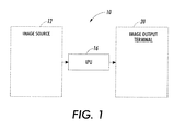
- FIG. 1 is a generalized functional block diagram of an exemplary marking system according to this invention
- FIG. 2 is an exemplary xerographic print engine according to the invention.
- FIG. 3 illustrates a region of a color graphic image and an internal representation, or pixel, that defines attributes for a dot in the color graphic image
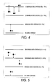
- FIGS. 4-5 illustrate pictorial representations of exemplary total area coverage adjustments according to aspects of the invention
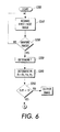
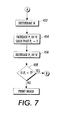
- FIGS. 6, 7 and 8 provide a flow diagram illustrating an exemplary method according to the invention.
- the present invention is directed to methods, systems and structures for improving coverage in a marking process, such as printing, photocopying or the like.
- Exemplary embodiments provide a color xerographic print engine.
- the invention is not limited to these. According to the present invention, improvement is achieved by identifying and compensating for color components that are within a zone of being unstable.
- An image input terminal 12 comprises an image data source, such as, a scanner, a computer image generator, an image storage device or the like.
- image data sources may also include a scanner, digital copier, facsimile device or other device suitable for generating, storing and/or transmitting image data, such as a client or server of a network, or the Internet, and especially the World Wide Web.
- the image processing unit 16 outputs data in a suitable format to an image output terminal 20, such as a digital color printer or other color image marking system.
- the marking system is a color xerographic print engine having four individual color markers (CYMK) as better illustrated in FIG. 2.
- Image source 12 may include any number of image sources suitable for generating or otherwise providing a digital document, such as illumination lamps, optics, a mechanical scanning drive, a raster input scanner (RIS), and a charge coupled device (CCD array) or full width subsampling scanning sensor array 14.
- Image source 12 captures the entire image from original document 38 and among other things, measures a set of primary color reflectances (device that reduces, green and blue reflectances) at each point of the original document.
- Image source 12 may convert these reflectances to device independent coordinates, including possibly a luminance-chrominance space, or they may be left in a format that is dependent upon image source 12.
- a preferred exemplary format is CYMK color space (cyan, yellow, magenta and black).
- Image source 12 transmits image data as electrical signals to an image processing system (ESS), indicated generally by the reference numeral 16.
- ESS 16 converts the image data signals provided by image source 12 to either a set of device independent coordinates, or to coordinates that are dependent upon a designated output device.
- ESS 16 also contains data control electronics that prepare and manage the image data flow to a raster output scanner (ROS), indicated generally by the reference numeral 20.
- the ESS transmits signals corresponding to the desired image to ROS 20, which creates the output copy image.
- ROS 20 includes a laser with rotating polygon mirror blocks. Via mirror 37, ROS illuminates the charged portion of photoconductive belt 24 of a print or marking engine, indicated generally by the reference numeral 22 to achieve a set of subtractive primary latent images.
- ROS 20 will expose the photoconductive belt to record multiple latent images which correspond to the signals transmitted from ESS 16.
- Each latent image is developed with a developer material having a different color component (colorant).
- a black latent image may be developed in lieu of or in addition to other (colored) latent images.
- These developed images are transferred to a copy sheet in superimposed registration with one another to form a multicolored image on the copy sheet. This multicolored image is then fused to the copy sheet to form a color copy.
- Developer units 40, 42, 44 and 46 apply toner particles of a specific color which corresponds to the complement of the specific color separated electrostatic latent image recorded on the photoconductive surface.
- developer units 40, 42, 44 and 46 there are separate developer units 40, 42, 44 and 46 for each of cyan, magenta, yellow and black, respectively.
- a color image can be defined as a set of dots, hereafter called "pixels".
- pixels Each pixel has a set of attributes associated with it.
- pixel attributes include the percentages of color components (e.g., cyan, magenta, yellow and black) that form a color in a particular color model (e.g., a CMYK color model) and the location of the dot in the color graphic image.
- the attributes can be used by computer rendering software applications to generate the color image.
- FIG. 3 illustrates a region of a color graphic image and an internal representation, or pixel, that defines attributes for a dot in the color graphic image.
- Region 202 represents all or a portion of a color graphic image output generated by a computer system that includes multiple rows and columns of dots.
- Dot 204 is included in region 202.
- dot 204 is typically represented within the computer system as a picture element, or pixel, that has a set of associated attributes.
- the attributes associated with pixel 206 can be used by a computer system to generate dot 204.
- Positional attributes 216A-216B identify the row and column positions of dot 204 in region 202. If, for example, the upper left comer of region 202 is at row 1 and column 1, dot 204 lies at row five and column five of region 202.
- Color attributes 218A-218D represent the contribution of the color components that define the color for dot 204. If the computer system is using a CMYK color model, color attributes 218A-218D specify the percentage of each of the cyan (C), magenta (M), yellow (Y) and black (K) color components that can form a color in the CMYK color model, for example. Color attributes 218A-218D can be specified as percentages that represent the percentage of each color that is to be used to create the color for dot 204. For example, color attributes 218A-218D can specify 50% of the total possible amount of C, 25% of the total possible amount of M, 75% of the total possible amount of Y and 50% of the total possible amount of K should be used to generate dot 204.
- the percentages specified for color attributes 218A-218D can also be defined as a number. For example, if 8 bits are used to define a color component's value, there can be 2 8 or 256 values. The value is typically expressed as a range from 0 to 255. FIG. 3 also illustrates possible values for C, M, Y and K using an 8-bit value range between 0 and 255, inclusive. For example, the 50% values for cyan and black may be expressed as 127. The 25% and 75% values for magenta and yellow may be expressed as 63 and 191, respectively.
- color attributes 218A-218D are translated into an amount of colorant, e.g., a color ink or toner.
- color attributes 218A-218D specify the levels of colorants 208A-208D that are used to generate dot 204.
- colorants 208A-208D can be color ink or toner, if dot 204 is to be output by a marking system such as a color printer or copier.
- Gray Component Replacement/Undercolor Removal (GCR/UCR) schemes are designed to replace the gray component of a color with black.
- individual color components are defined by cyan (C), magenta (M), yellow (Y) and black (K) color components.
- the gray component of a color in the CMYK color model is formed from equal amounts of C, M and Y color components.
- Such a component is sometimes referred to as a process black, since when combined the colors simulate a pure black colorant.
- One technique for determining the gray component in a CMYK color model is to determine the CMY color component that has the least value, since each of the CMY color components has that value in common. For example, if a color in the CMYK color model is composed of 50% of C, 35% of M and 25% of Y, the gray component is the lesser of the three, or 25%. Each of C, M and Y contribute this amount to the color's gray component.
- GCR/UCR schemes each of which uses a technique for determining the portion of the gray component that is to be replaced by black.
- CMYK color model an amount subtracted from the C, M, and Y components is added to the black component.
- 25% of C, M and Y is removed and 25% is added to the K component. If the K component had an initial value of 50%, the resulting values would be 25%, 10%, 0%, and 75% for the C, M, Y and K color components, respectively.
- the result of the GCR/UCR schemes is a total amount of colorant (i.e., totals for the C, M, Y and K color components) which is referred to as a GCR/UCR total.
- Conventional GCR/UCR techniques can overly reduce the saturation levels of color images and/or fail to ensure that a resulting GCR/UCR total satisfies individual colorant throughput levels, a threshold total area coverage (TAC) amount. That is, conventional GCR/UCR has been used for purposes other than individual throughput considerations.
- TAC is a measure of the total amount of colorant applied to an area (e.g., dot 204) of the output medium.
- the GCR/UCR total may unnecessarily dilute images by overly reducing color components C, M, and Y, and therefore overly reducing the saturation (density) level of color images.
- the GCR/UCR total may provide insufficient color component reduction such that the GCR/UCR total is greater than an allowed TAC threshold amount.
- a threshold TAC amount can be used to limit the amount of colorant used to, for example, reduce cost and/or to ensure that the total amount of ink applied does not exceed the amount that can be absorbed by the output medium.
- aspects of this invention achieve control of individual color throughput through shifting of color balances using principles of GCR/UCR. It has been found that each developer unit should have a minimum acceptable throughput to prevent problems, such as improper developer charge, lubrication properties and others. Through conventional software techniques, it is possible to determine individual color component throughput by analyzing the separate color space data. Through experimentation or empirical formulas, minimum and possibly maximum throughput values can be derived for each particular developer. For example, in the following exemplary embodiments, it is assumed that an acceptable minimum area coverage is 5% of the image. Such a throughput has been found to keep toner charging properties adequate for proper printing. For typical xerographic systems, the minimum acceptable area coverage is in the range of 1% to 5%, for each developer subsystem.
- magenta (M) is below desirable area coverage (throughput).
- One way to increase this is through substitution of "process black" or gray component replacement for part of the black (K) coverage. This is achieved by adding equal parts of C, Y and M to form process black and reducing the black coverage by this amount. For example, as shown, one possible solution is to add 3% to M making 5% total (i.e., at the minimum area coverage). Then, equal amounts (3%) are also added to each of Y and C.
- Black (K) is then decreased by this amount. This example thus reduces the pure black coverage by 3% and substitutes 3% coverage by process black (equal amounts of C, Y, M) to achieve minimum throughput for all colors to keep individual developer units at efficient levels (i.e., all above the threshold 5% TAC).
- FIGS. 6-8 provide a flowchart illustrating one exemplary method according to the invention that performs gray component replacement to satisfy individual color throughput levels.
- step S310 the system obtains an image at step S310, and determines the color parameters for the image. Then, in step S310, a determination is made whether the image is a graphic image. If the image is either text or an all black image, the following steps described below are assumed to be not applicable, and so the process repeats steps S310 and S320. If the next image to be printed is determined to be a graphic image in step S320, a threshold T is determined in step S330.
- the threshold is a minimum level that would assure development stability.
- the threshold level (driven by the materials design including additive levels and the development subsystem mechanical and electrical design) is empirically determined through stress testing.
- step S330 the individual component parameters Pi for and suitable level amounts each color component are determined for the graphic image in step S340.
- Pi includes the non-gray component color parameters for cyan (P C ), magenta (P M ) and yellow (P Y ).
- step S350 it is determined which if any of the color parameters Pi are below the threshold parameter T. If none of the color components (Pi) are below the threshold T then the image is output, e.g., by printing, in its current state.
- step S350 determines whether one or more of the non-gray color components is determined at step S350 to be below the threshold. If a color component parameter is below the threshold, it is considered unstable.
- step S454 the parameter for the unstable color component (P L ) is increased by at least 'A' such that the unstable color component is at least equal to the threshold T, and the remaining stable color components are also increased by 'A'.
- each of the C, Y and M components would be increased by 'A" for a gray component (or process black) that can be substituted for an equal amount of the black image.
- the black component parameter (P K ) is accordingly decreased by'A' in step S456.
- step S458 After bringing all of the non-gray component parameters into the stable development zone, a determination is made in step S458 as to whether the black component parameter is still stable, or in other words, is still above the threshold T. If the black component parameter is still in the zone of stability, then the image is output. If not, then the process continues to routine B (Fig. 8).
- step S562 of routine B all of the parameters are returned to their original numbers, since the first possible solution was found unacceptable.
- step S564 a second option is pursued in which the color parameter P L is reduced to zero (0), and 'A' is determined to be the amount that P L was reduced to bring it to zero.
- the remaining color component parameters are also decreased by'A' in step S566, and the black component parameter is increased by 'A' in step S568.
- the associated housing for the P L component is turned off in step S570.
- a determination is made as to whether any of the non-gray color component parameters are below the threshold T in step S571. If none of the color component parameters are below the threshold T, the image is output. If any of the non-gray color component parameters are below the threshold, the process continues to routine C.
- step S573 of routine C all of the non-gray color component parameters are increased by an amount 'A' such that P L is equal to the threshold T.
- step S574 P K is decreased by 'A' and the image is output.
- the algorithm may assure that any areas that needed the low throughput color component to make another color would be considered in the calculation. For example, if the Magenta (M) component could not be reduced to zero because it is needed for another non-black color combination, the algorithm could default to the first part of the invention as shown in steps S573 and S574 rather than attempting to decrease the color component entirely.
- M Magenta
- the present invention is implemented where two or more color parameters are running below the threshold. Similar computations are derived to find a solution where all non-gray color components are above the threshold or entirely off.
Landscapes
- Engineering & Computer Science (AREA)
- Multimedia (AREA)
- Signal Processing (AREA)
- Color Image Communication Systems (AREA)
- Facsimile Image Signal Circuits (AREA)
- Color, Gradation (AREA)
- Color Electrophotography (AREA)
Applications Claiming Priority (2)
| Application Number | Priority Date | Filing Date | Title |
|---|---|---|---|
| US756304 | 1996-11-25 | ||
| US10/756,304 US7245763B2 (en) | 2004-01-14 | 2004-01-14 | Gray component replacement as part of marking process control algorithm |
Publications (2)
| Publication Number | Publication Date |
|---|---|
| EP1555806A2 true EP1555806A2 (de) | 2005-07-20 |
| EP1555806A3 EP1555806A3 (de) | 2006-08-02 |
Family
ID=34620668
Family Applications (1)
| Application Number | Title | Priority Date | Filing Date |
|---|---|---|---|
| EP05100207A Ceased EP1555806A3 (de) | 2004-01-14 | 2005-01-14 | Graukomponentersetzung als Teil eines Steuerungsalgorithmus eines Markierverfahrens |
Country Status (3)
| Country | Link |
|---|---|
| US (1) | US7245763B2 (de) |
| EP (1) | EP1555806A3 (de) |
| JP (1) | JP2005202401A (de) |
Families Citing this family (6)
| Publication number | Priority date | Publication date | Assignee | Title |
|---|---|---|---|---|
| JP4442879B2 (ja) * | 2004-07-28 | 2010-03-31 | キヤノン株式会社 | 画像形成装置及び色信号変換方法 |
| US20070076260A1 (en) * | 2005-09-02 | 2007-04-05 | Upton Stephen D | Color management system tool and method |
| KR101329770B1 (ko) | 2008-08-08 | 2013-11-15 | 삼성전자주식회사 | 이미지 보정 방법과 이를 위한 화상형성장치 그리고 이미지의 번짐 현상 보정 방법 |
| US8593692B2 (en) * | 2009-08-12 | 2013-11-26 | Xerox Corporation | Systems and methods for building a color lookup table for a printer |
| US8335015B2 (en) * | 2009-09-16 | 2012-12-18 | Xerox Corporation | Systems and methods for building a color lookup table for a printer |
| EP3591954A1 (de) * | 2018-07-04 | 2020-01-08 | OCE Holding B.V. | Verfahren zur verbesserung der mechanischen robustheit eines farbdrucks |
Family Cites Families (15)
| Publication number | Priority date | Publication date | Assignee | Title |
|---|---|---|---|---|
| US5172223A (en) * | 1987-12-29 | 1992-12-15 | Canon Kabushiki Kaisha | Method of processing a color image to obtain color and black reproduction signals |
| US5305119A (en) | 1992-10-01 | 1994-04-19 | Xerox Corporation | Color printer calibration architecture |
| US5402245A (en) * | 1994-01-27 | 1995-03-28 | Hewlett-Packard Company | Bi-level digital color printer system exhibiting improved undercolor removal and error diffusion procedures |
| US5734800A (en) * | 1994-11-29 | 1998-03-31 | Pantone, Inc. | Six-color process system |
| CA2169902A1 (en) * | 1995-03-16 | 1996-09-17 | Allan Chiwan Cheung | Combined color halftoning |
| JP3299085B2 (ja) | 1995-08-25 | 2002-07-08 | ブラザー工業株式会社 | 色信号変換装置及びカラーインクジェットプリンタ |
| US5923774A (en) * | 1996-05-08 | 1999-07-13 | Canon Information Systems, Inc. | Matrix-based gray component replacement for color halftoning |
| JPH1013697A (ja) | 1996-06-18 | 1998-01-16 | Canon Inc | 画像処理装置およびその方法 |
| US5894358A (en) | 1996-06-27 | 1999-04-13 | Xerox Corporation | Adaptable color density management system |
| JPH1051656A (ja) * | 1996-08-05 | 1998-02-20 | Matsushita Electric Ind Co Ltd | 下色除去装置 |
| US6239886B1 (en) * | 1998-01-08 | 2001-05-29 | Xerox Corporation | Method and apparatus for correcting luminance and chrominance data in digital color images |
| US6084689A (en) | 1998-03-11 | 2000-07-04 | Colorbus, Inc. | Method and apparatus for saturation compensation in total ink limited output |
| US6134398A (en) | 1998-12-22 | 2000-10-17 | Xerox Corporation | Electrostatographic reproduction machine having dual mode development unit control apparatus and method |
| US6233411B1 (en) | 2000-06-07 | 2001-05-15 | Xerox Corporation | Method and apparatus for stabilizing productivity of an electrostatographic toner image reproduction machine |
| JP4038998B2 (ja) | 2001-02-23 | 2008-01-30 | セイコーエプソン株式会社 | 色の光源依存性を抑えた印刷 |
-
2004
- 2004-01-14 US US10/756,304 patent/US7245763B2/en not_active Expired - Fee Related
-
2005
- 2005-01-11 JP JP2005004291A patent/JP2005202401A/ja active Pending
- 2005-01-14 EP EP05100207A patent/EP1555806A3/de not_active Ceased
Also Published As
| Publication number | Publication date |
|---|---|
| US7245763B2 (en) | 2007-07-17 |
| EP1555806A3 (de) | 2006-08-02 |
| US20050151982A1 (en) | 2005-07-14 |
| JP2005202401A (ja) | 2005-07-28 |
Similar Documents
| Publication | Publication Date | Title |
|---|---|---|
| EP0929190B1 (de) | Verfahren und Vorrichtung zur Korrektur von Luminanz- und Chrominanzwerten in digitalen Farbbildern | |
| US6014457A (en) | Image processing apparatus | |
| CN101867682B (zh) | 图像处理装置及图像处理方法 | |
| JP3787534B2 (ja) | 画像処理装置、画像処理方法及び画像処理プログラム | |
| US7826089B2 (en) | Image processing method, program, computer readable information recording medium, image processing apparatus and image forming apparatus | |
| US6751346B2 (en) | Image processing method and apparatus, and recording medium | |
| US20080186533A1 (en) | Image processing apparatus | |
| JP5959815B2 (ja) | 画像処理装置およびその方法 | |
| US8773723B2 (en) | Generating color separation table for printer having color forming materials with high and low relative densities using a gamut boundary to limit use of dark color material | |
| CN100435034C (zh) | 成像装置和方法 | |
| JP2001292331A (ja) | 画像処理方法及び装置、画像処理システム及び記録媒体 | |
| JP2004112470A (ja) | 色調補正方法、画像処理システム、画像処理装置、プログラム、記憶媒体 | |
| JPH1175078A (ja) | 色補正画像プリント方法 | |
| US7245763B2 (en) | Gray component replacement as part of marking process control algorithm | |
| JP2015156570A (ja) | 色処理装置、画像形成装置およびプログラム | |
| EP0944244B1 (de) | Verfahren und Vorrichtung für das Reduzieren der Kompliziertheit von Farbkorrekturen unter Verwendung der Unterabtastung | |
| US8559080B2 (en) | Image forming apparatus and computer readable medium for image forming | |
| US20060279589A1 (en) | Image processing apparatus and image forming apparatus | |
| JP6630086B2 (ja) | 画像処理装置、画像処理方法及びプログラム | |
| JP4215348B2 (ja) | 印刷不可能な色値を印刷可能な色値に変換する方法、カラー画像を再生する画像再生システム、及び、この画像再生システムに適した色変換手段を備える制御手段 | |
| US7916368B2 (en) | Image processing device and method for maintaining the color shade of low-chroma color regions of an image | |
| US7460274B2 (en) | Controlling apparatus for outputting processed image data | |
| JP2006238024A (ja) | 画像処理装置、画像処理方法、プログラムおよび記録媒体 | |
| JP4452639B2 (ja) | 画像処理装置、画像処理方法、その方法をコンピュータに実行させるプログラム、および記録媒体 | |
| JP2006159709A (ja) | 画像出力装置、画像出力方法及び記録媒体 |
Legal Events
| Date | Code | Title | Description |
|---|---|---|---|
| PUAI | Public reference made under article 153(3) epc to a published international application that has entered the european phase |
Free format text: ORIGINAL CODE: 0009012 |
|
| AK | Designated contracting states |
Kind code of ref document: A2 Designated state(s): AT BE BG CH CY CZ DE DK EE ES FI FR GB GR HU IE IS IT LI LT LU MC NL PL PT RO SE SI SK TR |
|
| AX | Request for extension of the european patent |
Extension state: AL BA HR LV MK YU |
|
| PUAL | Search report despatched |
Free format text: ORIGINAL CODE: 0009013 |
|
| AK | Designated contracting states |
Kind code of ref document: A3 Designated state(s): AT BE BG CH CY CZ DE DK EE ES FI FR GB GR HU IE IS IT LI LT LU MC NL PL PT RO SE SI SK TR |
|
| AX | Request for extension of the european patent |
Extension state: AL BA HR LV MK YU |
|
| 17P | Request for examination filed |
Effective date: 20070202 |
|
| AKX | Designation fees paid |
Designated state(s): DE FR GB |
|
| 17Q | First examination report despatched |
Effective date: 20070516 |
|
| STAA | Information on the status of an ep patent application or granted ep patent |
Free format text: STATUS: THE APPLICATION HAS BEEN REFUSED |
|
| 18R | Application refused |
Effective date: 20111217 |