EP1555559B1 - Kompaktes Objektiv - Google Patents
Kompaktes Objektiv Download PDFInfo
- Publication number
- EP1555559B1 EP1555559B1 EP04253717A EP04253717A EP1555559B1 EP 1555559 B1 EP1555559 B1 EP 1555559B1 EP 04253717 A EP04253717 A EP 04253717A EP 04253717 A EP04253717 A EP 04253717A EP 1555559 B1 EP1555559 B1 EP 1555559B1
- Authority
- EP
- European Patent Office
- Prior art keywords
- lens
- image
- imaging lens
- aberration
- imaging
- Prior art date
- Legal status (The legal status is an assumption and is not a legal conclusion. Google has not performed a legal analysis and makes no representation as to the accuracy of the status listed.)
- Expired - Lifetime
Links
Images


Classifications
-
- G—PHYSICS
- G02—OPTICS
- G02B—OPTICAL ELEMENTS, SYSTEMS OR APPARATUS
- G02B13/00—Optical objectives specially designed for the purposes specified below
- G02B13/001—Miniaturised objectives for electronic devices, e.g. portable telephones, webcams, PDAs, small digital cameras
- G02B13/0015—Miniaturised objectives for electronic devices, e.g. portable telephones, webcams, PDAs, small digital cameras characterised by the lens design
- G02B13/002—Miniaturised objectives for electronic devices, e.g. portable telephones, webcams, PDAs, small digital cameras characterised by the lens design having at least one aspherical surface
- G02B13/003—Miniaturised objectives for electronic devices, e.g. portable telephones, webcams, PDAs, small digital cameras characterised by the lens design having at least one aspherical surface having two lenses
-
- G—PHYSICS
- G02—OPTICS
- G02B—OPTICAL ELEMENTS, SYSTEMS OR APPARATUS
- G02B1/00—Optical elements characterised by the material of which they are made; Optical coatings for optical elements
- G02B1/04—Optical elements characterised by the material of which they are made; Optical coatings for optical elements made of organic materials, e.g. plastics
- G02B1/041—Lenses
-
- G—PHYSICS
- G02—OPTICS
- G02B—OPTICAL ELEMENTS, SYSTEMS OR APPARATUS
- G02B13/00—Optical objectives specially designed for the purposes specified below
- G02B13/18—Optical objectives specially designed for the purposes specified below with lenses having one or more non-spherical faces, e.g. for reducing geometrical aberration
-
- G—PHYSICS
- G02—OPTICS
- G02B—OPTICAL ELEMENTS, SYSTEMS OR APPARATUS
- G02B9/00—Optical objectives characterised both by the number of the components and their arrangements according to their sign, i.e. + or -
- G02B9/04—Optical objectives characterised both by the number of the components and their arrangements according to their sign, i.e. + or - having two components only
- G02B9/06—Optical objectives characterised both by the number of the components and their arrangements according to their sign, i.e. + or - having two components only two + components
- G02B9/08—Optical objectives characterised both by the number of the components and their arrangements according to their sign, i.e. + or - having two components only two + components arranged about a stop
-
- G—PHYSICS
- G03—PHOTOGRAPHY; CINEMATOGRAPHY; ANALOGOUS TECHNIQUES USING WAVES OTHER THAN OPTICAL WAVES; ELECTROGRAPHY; HOLOGRAPHY
- G03B—APPARATUS OR ARRANGEMENTS FOR TAKING PHOTOGRAPHS OR FOR PROJECTING OR VIEWING THEM; APPARATUS OR ARRANGEMENTS EMPLOYING ANALOGOUS TECHNIQUES USING WAVES OTHER THAN OPTICAL WAVES; ACCESSORIES THEREFOR
- G03B9/00—Exposure-making shutters; Diaphragms
- G03B9/02—Diaphragms
Definitions
- the present invention relates to an imaging lens.
- an imaging lens it is necessary that the optical length, defined as the distance from the incidence plane on the object side of the imaging lens to the image plane (image-forming surface of the CCD or similar), be short. That is, in the design of the imaging lens, measures must be taken to reduce insofar as possible the ratio of the optical length to the combined focal length of the imaging lens.
- an imaging lens with a short optical length that is, the ratio of the optical length to the focal length of which is small, may be called a "compact" lens.
- the optical length should be made shorter than the thickness of the portable telephone unit.
- the back focus defined as the distance from the emission plane on the image side of the imaging lens to the image plane, be as long as possible. That is, in the design of the imaging lens, measures should be taken to increase insofar as possible the ratio of the back focus to the combined focal length of the imaging lens. This is due to the need to insert filters, cover glass, and other components between the imaging lens and the image plane.
- the various aberrations of an imaging lens are corrected to amounts sufficiently small that distortion of the image formed by this imaging lens is not recognized by visual perception, and sufficiently small as to satisfy the requirements of the integration density of the imaging components (also called "pixels"). That is, the various aberrations must be corrected satisfactorily; below, an image for which various aberrations are satisfactorily corrected may be called a "satisfactory image”.
- imaging lenses with a two-component configuration have been disclosed which are appropriate for use in image equipment employing a CCD, CMOS device or other solid-state image pickup component, of which portable computers and videophones are representative.
- CCD compact disc-read only memory
- CMOS complementary metal-oxide-semiconductor
- solid-state image pickup component of which portable computers and videophones are representative.
- such lenses are all designed for small size and light weight.
- an infrared lens has been disclosed with a two-component configuration comprising two meniscus lenses (a first lens and a second lens), designed for low cost and for reduced weight, which is compact and has adequate image-forming performance for practical use.
- a first lens an infrared lens
- a second lens designed for low cost and for reduced weight, which is compact and has adequate image-forming performance for practical use.
- an infrared lens has a broad interval D between the first lens and second lens, so that as a result the optical length is necessarily long, and design of a sufficiently compact lens system is difficult.
- the ratio D/f of the interval D between the first and second lenses to the focal length f of the entire system is at least 0.8. Consequently, the ratio of the optical length to the focal length of the entire system is large at approximately 1.5 (the value for the lens in Embodiment 6, with the smallest value, is 1.4236), so that the optical length of such lenses is long.
- an anamorphic attachment lens As a second two-component lens, an anamorphic attachment lens has been disclosed (see for example Japanese Unexamined Patent Application Publication No. 2000-81568), in which an image of the object is focused with different vertical and horizontal magnifications by one afocal lens comprising cylindrical surfaces both of which have refractive power only in the same direction and have radii of curvature with the same sign, and which can project images more slim or more thick than the actual object.
- Such an anamorphic attachment lens is positioned and used on the object side of a still camera lens system in particular.
- the anamorphic attachment lens is a lens system configured as a two-component lens
- the surface shapes of the component lenses of the anamorphic attachment lens are not spherical, as in the case of ordinary lenses, but are cylindrical surfaces.
- the basic configuration differs from that of the imaging lens of the present invention.
- an objective lens for recording and reproduction of information on optical information recording media a large operating distance for which is secured has been disclosed, in which a lens group having two components with positive refractive power has a large NA (numerical aperture) of 0.85, and which is appropriate for incorporation into optical pickup devices with light source wavelengths of 500 nm or below, with chromatic aberration corrected satisfactorily (see for example Japanese Unexamined Patent Application Publication No. 2003-167187).
- objective lenses for high-performance, small-size optical pickups, having a large numerical aperture and long working distance have been disclosed (see for example Japanese Unexamined Patent Application Publication No. 2003-5026, Japanese Unexamined Patent Application Publication No. 2003-5027, and Japanese Unexamined Patent Application Publication No. 2003-5055).
- these objective lenses are designed with a small NA, for the purpose of using the objective lens to focus parallel rays into as small an area as possible on the information recording surface; the imaging lenses of the present invention are inherently different in concept from these. Consequently the values of the focal lengths, back focuses, and optical lengths of each of the two lenses making up the lens system, and the interval between lenses, are different from the imaging lenses of the present invention.
- a numerical aperture of 0.85 or higher, converted into an F-number yields a value of 1 or below
- the F-number of an imaging lens of the present invention (F no ) is in the range 2.0 ⁇ F no ⁇ 4.0, for a very bright lens.
- indexes representing the brightness of a lens in order to distinguish between the numerical aperture (NA) represented by the product n•sin(u) of the object-side refractive index n and the angle u subtended by the radius of the entrance pupil, and the F-number represented as the ratio f/D in of the lens focal length f to the diameter of the entrance pupil D in , in this specification a value representing the numerical aperture will be denoted by NA, and a value representing the F-number will be denoted by F no .
- a bright, compact infrared lens is disclosed (see for example Japanese Unexamined Patent Application Publication No. 2003-295052), in which comparatively inexpensive material is used, costs are reduced, and the effects of unwanted orders of diffracted light, which are a disadvantage of diffraction gratings, are eliminated.
- a diffraction grating is formed on the concave surface of a meniscus lens positioned on the object side.
- this image-forming lens system has a short back focus, so that insertion of a filter or similar between lenses and image plane to block infrared light is difficult.
- the ratio b f /f of the back focus b f to the focal length f of the entire system is at most 0.38 (Embodiment 5).
- imaging lenses comprising an image-forming lens (first lens) and corrective lens (second lens) (see for example Japanese Unexamined Patent Application Publication No. 2000-66094, Japanese Unexamined Patent Application Publication No. 2000-66095, and Japanese Unexamined Patent Application Publication No. 2000-66096).
- these imaging lenses have a configuration in which the thickness of the image-forming lens on the optical axis is large. Consequently the refractive index tends to be distributed unevenly when configuring the lens, and image distortion and similar occur due to such uneven distribution of the refractive index, so that in some cases the image quality which should result from lens design cannot be obtained.
- an imaging lens with comparatively small image dimensions, and which in particular enables performance appropriate to mounting in small-size image pickup equipment, is disclosed (see for example Japanese Unexamined Patent Application Publication No. 2004-4620).
- This imaging lens is configured by positioning, in order from the object side, an aperture diaphragm, a first lens, and a second lens.
- the ratio d/f of the optical length d to the focal length f for the entire system exceeds 1.3, except for the imaging lens disclosed as Embodiment 9. That is, in this design the optical length is long, and compactness cannot be completely attained.
- the ratio d/f of the optical length d to the focal length f for the entire system of the imaging lens disclosed as Embodiment 9 is 1.137; but the ratio D 2 /f of the interval D 2 between the first and second lenses to the focal length f of the entire system for this imaging lens is extremely small, at 0.11. Consequently in this configuration, a diaphragm could not easily be inserted as a second diaphragm between the first and second lenses.
- An embodiment of the present invention provides an imaging lens, the F-number of which is in the range 2.0 to 4.0, configured with only two component lenses, with a short lens optical length, and capable of obtaining satisfactory images.
- a further object is to provide an imaging lens in which, by providing a diaphragm between the first lens and second lens to adequately eliminate flare, image contrast can be increased sufficiently that sharp images can be obtained.
- a further embodiment of the present invention provides an imaging lens which achieves low costs and light weight by using plastic material for all the lenses (two lenses) making up the imaging lens.
- a "plastic material” is a polymer material which can be molded to form a lens by plastic deformation using heat or pressure, or both, and which is transparent to visible light.
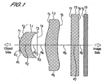
- An imaging lens is configured by positioning, in order from an object side to an image side, an aperture diaphragm S 1 , a first lens L 1 , a second diaphragm S 2 , and a second lens L 2 .
- the first lens L 1 is a meniscus-shape lens, with the convex surface facing the object side, having positive refractive power.
- the second lens L 2 is a meniscus-shape lens, with the convex surface facing the object side, having positive refractive power.
- the imaging lens satisfies the following conditions. 0.3 ⁇ f 1 / f 2 ⁇ 1.0 0.4 ⁇ b f / f ⁇ 0.5 1.0 ⁇ d / f ⁇ 1.3 0.12 ⁇ D 2 / f ⁇ 0.30 2.0 ⁇ F n o ⁇ 4.0
- f is the combined focal length of the imaging lens
- f 1 is the focal length of the first lens L 1
- f 2 is the focal length of the second lens L 2
- b f is the distance (in air) from the image-side surface of the second lens L 2 to the image plane
- d is the distance (in air) from the object-side surface of the first lens L 1 to the image plane
- D 2 is the interval between the first lens L 1 and the second lens L 2
- F no is the F-number.
- first lens L 1 and second lens L 2 making up an imaging lens of the present invention be formed from material with an Abbe number from 30 to 60. Also, the first lens L 1 and second lens L 2 making up an imaging lens of the present invention may be formed from cycloolefin plastic or polycarbonate materials.
- the above condition equation (1) is a condition stipulating the ratio f 1 /f 2 of the focal length f 1 of the first lens L 1 to the focal length f 2 of the second lens L 2 . If this ratio f 1 /f 2 is larger than a certain lower limit, the various aberrations occurring in the first lens L 1 can be corrected. In particular, by correcting distortion, extreme deformity of the image resulting from the existence of this distortion can be prevented. Further, it is possible to prevent a situation in which molding is difficult because the radius of curvature of the first lens L 1 is too small.
- the lens can be made sufficiently compact to enable use as an imaging lens for mounting in a portable telephone, the image input device of a personal computer, a digital camera, surveillance CCD camera, inspection equipment and similar. That is, the back focus can be made sufficiently short, and as a result the optical length is not too long. Moreover, various aberrations occurring in the second lens L 2 can be adequately corrected.
- condition equation (2) is a condition to secure an adequate length for the distance b f from the image-side surface of the second lens L 2 to the image plane (the back focus), and to secure space for insertion of cover glass, a filter, or similar. That is, this condition equation stipulates a condition to be satisfied by the ratio b f /f of the back focus b f to the combined focal length f of an imaging lens of the present invention in order to enable insertion of cover glass, a filter or similar.
- condition equation (2) If the ratio b f /f is larger than the lower limit given by condition equation (2), an adequate back focus can be secured, and a construction is possible enabling easy insertion of cover glass, a filter, or similar.
- condition equation (2) On the other hand, if the ratio b f /f is smaller than the upper limit given by condition equation (2), the back focus is not too long and an imaging lens can be realized in which an optical length is obtained appropriate for mounting in a portable telephone unit, an image input device of a personal computer, and similar. Even if the ratio b f /f exceeds the upper limit given by the condition equation (2), the possibility of making the interval between the first lens L 1 and second lens L 2 short to shorten the optical length can be studied; but at present it is difficult to form an imaging lens enabling acquisition of satisfactory images in which various aberrations have been adequately corrected.
- the lens shapes are such that it is difficult to pour the lens material into molds so as to form a shape which accurately reflects the shape of the mold.
- condition equation (3) is a condition equation stipulating the ratio d/f of the distance d from the object-side surface of the first lens L 1 to the image plane (the optical length) to the combined focal length f of an imaging lens of the present invention. If the ratio d/f is larger than the lower limit given by condition equation (3), the thicknesses of the first lens L 1 and second lens L 2 can be set such that injection molding of these lenses is possible. Also, the back focus b f can be set sufficiently long that the effective diameter of the second lens is not so large as to impede compactness of the imaging lens.
- the optical length is not so long that compactness of the imaging lens of the present invention is impeded, and a satisfactory image can be obtained in which the brightness is uniform across the entire image, without making the ratio of the quantity of light at the periphery to the quantity of light at the center of the image too small.
- condition equation (4) is a condition equation which specifies the range for values of the ratio D 2 /f of the interval D 2 between the first lens L 1 and second lens L 2 and the combined focal length f of an imaging lens of the present invention. If the ratio D 2 /f is larger than the lower limit given by condition equation (4), then the interval between the image-side surface r 3 of the first lens L 1 and the object-side surface r 5 of the second lens L 2 is not too small, and a second diaphragm S 2 can be inserted into the space between the first lens L 1 and the second lens L 2 .
- a second diaphragm S 2 plays an important role in obtaining sharp images with sufficiently high contrast, by sufficiently eliminating rays not contributing to image formation which occur on the outer periphery of the first lens L 1 and second lens L 2 and inside the cylindrical barrel holding the imaging lens.
- image plane curvature of field occurring in the negative direction can be made sufficiently small. That is, by adjusting the resolving power at the center of the image to the extent that a satisfactory image is obtained, the effect of movement of the satisfactory image position at the periphery of the image toward the object side from the image plane position can be reduced sufficiently.
- an interval between the image-side surface r 3 of the first lens L 1 and the object-side surface r 5 of the second lens L 2 can be secured which is sufficiently large to enable insertion of a second diaphragm S 2 .
- curvature of field occurring in the negative direction is not so large that adequate resolution at the periphery of the image is not obtained. That is, by adjusting the resolving power at the center of the image sufficiently that a satisfactory image can be obtained, the image plane curvature of field occurring in the negative direction can be made sufficiently small. In other words, by adjusting the resolving power at the center of the image sufficiently to obtain a satisfactory image, the effect of forward movement from the image plane position of the satisfactory resolution position at the periphery of the image can be reduced sufficiently.
- the ratio D 2 /f is smaller than the upper limit given by the condition equation (4), a situation in which the back focus is too short and the effective diameter of the second lens L 2 is too large, so that the imaging lens cannot be made compact, can be avoided. Further, curvature of field occurring in the positive direction is not so large that adequate resolution is not possible at the periphery of the image. That is, by adjusting the resolving power at the center of the image sufficiently that a satisfactory image is obtained, the image plane curvature of field occurring in the positive direction can be made sufficiently small. In other words, by adjusting the resolving power at the center of the image sufficiently to obtain a satisfactory image, the effect of backward movement from the image plane position of the satisfactory resolution position at the periphery of the image can be reduced sufficiently.
- condition equation (5) is a condition equation stipulating the range of values of the F-number of an imaging lens of the present invention. If the F-number is larger than the lower limit given by the condition equation (5), then a depth of field sufficient to enable use as an imaging lens mountable in a portable telephone, image input device for a personal computer, digital camera, surveillance CCD camera, inspection equipment and similar is secured. If the depth of field is too shallow, that is, if the F-number is too small, it is difficult to simultaneously focus over a broad range of the image, and use is impeded.
- condition equation (5) If on the other hand the F-number is smaller than the upper limit given by the condition equation (5), then an image with satisfactory brightness can be obtained, without excessively dark images, and without insufficient light quantity arriving at the image plane of the portable telephone, image input device for a personal computer, digital camera, surveillance CCD camera, inspection equipment, or similar.
- embodiments of the present invention seek to provide an imaging lens with an F-number in the range from 2.0 to 4.0, configured from only two lenses, with a short lens optical length, and from which satisfactory images are obtained.
- an imaging lens can be provided with sufficiently enhanced image contrast and from which sharp images are obtained.
- an imaging lens By means of an imaging lens according to embodiments of the present invention, it is possible to form all of the lenses (two lenses) making up the imaging lens of the present invention from plastic material, so that imaging lenses can be provided at low cost and which are light in weight.
- Fig. 1 is a drawing of the configuration of an imaging lens according to an embodiment of the present invention.
- the surface numbers, intervals between surfaces and other symbols defined in Fig. 1 are used in common in Fig. 2, Fig. 6, Fig. 10, and Fig. 14.
- the first and second lenses are denoted by L 1 and L 2 respectively.
- the image component comprising the image plane is denoted by 10
- the cover glass separating the image plane and lens system is denoted by 12
- the aperture diaphragm and second diaphragm are denoted by S 1 and S 2 respectively.
- the aperture portions of the aperture diaphragm S 1 and second diaphragm S 2 are indicated by line segments.
- the subscript i denotes the order in moving from the object side to the image side, and values are assigned corresponding to the lens surface number, the lens thickness, lens interval, and similar.
- r i is the radius of curvature on the axis of the ith surface
- d i is the distance from the ith surface to the i+1th surface
- N i is the refractivity of the material of the lens comprising the ith surface and i+1th surface
- v i is the Abbe number of the material of the lens from the ith surface to the i+1th surface.
- r i indicates the radius of curvature on the axis of the ith surface, and, so long as there is no chance of misunderstanding, may also refer to the ith surface itself.
- the optical length d is the result of adding d 1 to d 5 and further adding the back focus b f .
- the back focus b f is the distance on the optical axis from the image-side surface of the second lens L 2 to the image plane.
- the back focus b f is measured with the cover glass, inserted between the second lens L 2 and the image plane, removed. That is, in the state in which the cover glass is inserted, the geometrical distance from the image-side surface of the second lens L 2 to the image plane is greater than with the cover glass removed, due to the fact that the refractivity of the cover glass is greater than 1.
- the extent to which the back focus is longer is determined by the refractivity and thickness of the inserted cover glass.
- Aspheric data is shown in the rightmost columns of Table 1 through Table 4, together with surface numbers.
- Z is the depth from the plane tangent at the surface vertex
- c is the curvature of the surface in the vicinity of the optical axis
- h is the height from the optical axis
- k is the conic constant
- a 0 is the fourth-order aspheric coefficient
- B 0 is the sixth-order aspheric coefficient
- C 0 is the eighth-order aspheric coefficient
- D 0 is the tenth-order aspheric coefficient.
- Fig. 2, Fig. 6, Fig. 10, and Fig. 14 are summary views of lens configurations. Distortion aberration curves are shown in Fig. 3, Fig. 7, Fig. 11, and Fig. 15; astigmatic aberration curves appear in Fig. 4, Fig. 8, Fig. 12, and Fig. 16; and chromatic/spherical aberration curves appear in Fig. 5, Fig. 9, Fig. 13, and Fig. 17.
- a distortion aberration curve shows the aberration amount (the amount by which the tangent condition is not satisfied, expressed as a percentage along the horizontal axis) versus the distance from the optical axis (expressed as a percentage along the vertical axis, with the maximum distance from the optical axis within the image plane equal to 100).
- An astigmatic aberration curve shows the amount of aberration along the horizontal axis (in mm units) for a distance from the optical axis, similarly to a distortion aberration curve. Astigmatism is represented as aberration amounts (in mm units) in the meridional plane and in the sagittal plane.
- a chromatic/spherical aberration curve shows the amount of aberration along the horizontal axis (in mm units) for a distance of incidence h (F-number).
- aberration amounts are shown for the C line (light of wavelength 656.3 nm), the d line (light of wavelength 587.6 nm), the e line (light of wavelength 546.1 nm), the F line (light of wavelength 486.1 nm), and the g line (light of wavelength 435.8 nm).
- the refractivity is the refractivity for the d line (light of wavelength 587.6 nm).
- Embodiments 1 through 4 the radii of curvature of component lenses (in mm units), intervals between lenses (in mm units), refractivity of lens materials, Abbe number of lens materials, numerical aperture, and aspheric coefficients are listed for Embodiments 1 through 4.
- the combined focal length f is set to 1.0 mm.
- ZEONEX E48R (ZEONEX is a registered trademark, and E48R is a product number, of Nippon Zeon Co., Ltd.; hereafter simply called "Zeonex"), which is a cycloolefin plastic, was employed in the first lens L 1 and second lens L 2 .
- both the surfaces of the first lens L 1 and both the surfaces of the second lens L 2 are aspherical. That is, the number of aspherical surfaces is four in each of the embodiments.
- the Abbe number of the Zeonex E48R material of the first lens L 1 and second lens L 2 is 56 (the refractivity for the d line is 1.53). From simulation results it was found that if the Abbe number of the material of the lenses is in the range 30 to 60, no effective differences appear in the aberration and other lens performance parameters. That is, it was found that if the Abbe number is within the above range, then an imaging lens according to embodiment of the present invention, with various aberrations satisfactorily corrected compared with imaging lenses of the prior art, can be obtained. From this, the imaging lens of the present invention can also employ polycarbonate as the lens component material.
- a filter is inserted between the lens system and the image plane.
- glass with refractivity for the d line of 1.5168. The various aberrations explained below were calculated assuming the presence of such filters.
- Embodiment 1 satisfies all of the following condition equations (1) through (5). 0.3 ⁇ f 1 / f 2 ⁇ 1.0 0.4 ⁇ b f / f ⁇ 0.5 1.0 ⁇ d / f ⁇ 1.3 0.12 ⁇ D 2 / f ⁇ 0.30 2.0 ⁇ F n o ⁇ 4.0
- the aperture diaphragm S 1 is provided at the position of the first surface r 2 (the object-side surface) of the first lens L 1 .
- the F-number is 3.0, and the combined focal length f is 1.0 mm.
- Fig. 2 is a cross-sectional view of the imaging lens of Embodiment 1.
- the optical length is 1.193 mm, and the back focus is 0.463 mm, so that an adequate length can be secured for the combined focal length f.
- the value of d 3 +d 4 which is the interval between the second surface r 3 of the first lens L 1 and the first surface r 5 of the second lens L 2 , is set to 0.2738 mm, so that a sufficient interval is secured for insertion of the second diaphragm S 2 between the first lens L 1 and second lens L 2 .
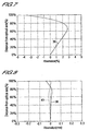
- Fig. 3 shows the distortion aberration curve 20
- Fig. 4 shows the astigmatic aberration curves (the aberration curve 22 in the meridional plane and the aberration curve 24 in the sagittal plane)
- Fig. 5 shows the chromatic/spherical aberration curves (the aberration curve 26 for the C line, aberration curve 28 for the d line, aberration curve 30 for the e line, aberration curve 32 for the F line, and aberration curve 34 for the g line).
- the vertical axes of the aberration curves in Fig. 3 and Fig. 4 indicate the distance from the optical axis of the image height, as a percentage.
- 100%, 80%, 70%, and 60% on the vertical axes correspond respectively to 0.650 mm, 0.520 mm, 0.455 mm, and 0.390 mm.
- the vertical axis in Fig. 5 indicates the distance of incidence h (F-number); the maximum corresponds to F3.0.
- the horizontal axis in Fig. 5 indicates the aberration magnitude.
- the absolute value of distortion aberration is maximum, at 3.78%, at an image height of 80% (image height 0.520 mm). At image heights of 0.650 mm or less, the absolute value of the aberration is within 3.78%.
- the absolute value of astigmatic aberration is maximum in the sagittal plane, at 0.0292 mm, at an image height of 80% (image height 0.520 mm). At image heights of 0.650 mm or less, the absolute value of the aberration is within 0.0292 mm.
- the absolute value of chromatic/spherical aberration is maximum, at 0.0355 mm, for the g line at a distance of incidence h of 100%, and the absolute value of the aberration is everywhere within 0.0355 mm.
- Embodiment 2 satisfies all of the following condition equations (1) through (5). 0.3 ⁇ f 1 / f 2 ⁇ 1.0 0.4 ⁇ b f / f ⁇ 0.5 1.0 ⁇ d / f ⁇ 1.3 0.12 ⁇ D 2 / f ⁇ 0.30 2.0 ⁇ F n o ⁇ 4.0
- the aperture diaphragm S 1 is provided at the position of the first surface r 2 (the object-side surface) of the first lens L 1 .
- the F-number is 3.0, and the combined focal length f is 1.0 mm.
- Fig. 6 is a cross-sectional view of the imaging lens of Embodiment 2.
- the optical length is 1.102 mm, and the back focus is 0.454 mm, so that an adequate length can be secured for the combined focal length f.
- the value of d 3 +d 4 which is the interval between the second surface r 3 of the first lens L 1 and the first surface r 5 of the second lens L 2 , is set to 0.1727 mm, so that a sufficient interval is secured for insertion of the second diaphragm S 2 between the first lens L 1 and second lens L 2 .
- Fig. 7 shows the distortion aberration curve 36
- Fig. 8 shows the astigmatic aberration curves (the aberration curve 38 in the meridional plane and the aberration curve 40 in the sagittal plane)
- Fig. 9 shows the chromatic/spherical aberration curves (the aberration curve 42 for the C line, aberration curve 44 for the d line, aberration curve 46 for the e line, aberration curve 48 for the F line, and aberration curve 50 for the g line).
- the vertical axes of the aberration curves in Fig. 7 and Fig. 8 indicate the distance from the optical axis of the image height, as a percentage. In Fig. 7 and Fig. 8, 100%, 80%, 70%, and 60% on the vertical axes correspond respectively to 0.650 mm, 0.520 mm, 0.455 mm, and 0.390 mm.
- the vertical axis in Fig. 9 indicates the distance of incidence h (F-number); the maximum corresponds to F3.0.
- the horizontal axis in Fig. 9 indicates the aberration magnitude.
- the absolute value of distortion aberration is maximum, at 3.63%, at an image height of 100% (image height 0.650 mm). At image heights of 0.650 mm or less, the absolute value of the aberration is within 3.63%.
- the absolute value of astigmatic aberration is maximum in the meridional plane, at 0.0399 mm, at an image height of 100% (image height 0.650 mm). At image heights of 0.650 mm or less, the absolute value of the aberration is within 0.0399 mm.
- the absolute value of chromatic/spherical aberration is maximum, at 0.0300 mm, for the g line at a distance of incidence h of 100%, and the absolute value of the aberration is everywhere within 0.0300 mm.
- Embodiment 3 satisfies all of the following condition equations (1) through (5). 0.3 ⁇ f 1 / f 2 ⁇ 1.0 0.4 ⁇ b f / f ⁇ 0.5 1.0 ⁇ d / f ⁇ 1.3 0.12 ⁇ D 2 / f ⁇ 0.30 2.0 ⁇ F n o ⁇ 4.0
- the aperture diaphragm S 1 is provided at the position of the first surface r 2 (the object-side surface) of the first lens L 1 .
- the F-number is 3.0, and the combined focal length f is 1.0 mm.
- Fig. 10 is a cross-sectional view of the imaging lens of Embodiment 3.
- the optical length is 1.079 mm, and the back focus is 0.462 mm, so that an adequate length can be secured for the combined focal length f.
- the value of d 3 +d 4 which is the interval between the second surface r 3 of the first lens L 1 and the first surface r 5 of the second lens L 2 , is set to 0.1435 mm, so that a sufficient interval is secured for insertion of the second diaphragm S 2 between the first lens L 1 and second lens L 2 .
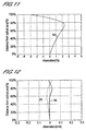
- Fig. 11 shows the distortion aberration curve 52
- Fig. 12 shows the astigmatic aberration curves (the aberration curve 54 in the meridional plane and the aberration curve 56 in the sagittal plane)
- Fig. 13 shows the chromatic/spherical aberration curves (the aberration curve 58 for the C line, aberration curve 60 for the d line, aberration curve 62 for the e line, aberration curve 64 for the F line, and aberration curve 66 for the g line).
- the vertical axes of the aberration curves in Fig. 11 and Fig. 12 indicate the distance from the optical axis of the image height, as a percentage, and each vertical axis indicates the aberration in percentage terms and in mm units.
- 100%, 80%, 70%, and 60% on the vertical axes correspond respectively to 0.645 mm, 0.516 mm, 0.451 mm, and 0.387 mm.
- the vertical axis in Fig. 13 indicates the distance of incidence h (F-number); the maximum corresponds to F3.0.
- the horizontal axis in Fig. 13 indicates the aberration magnitude.
- the absolute value of distortion aberration is maximum, at 3.07%, at an image height of 100% (image height 0.645 mm). At image heights of 0.645 mm or less, the absolute value of the aberration is within 3.07%.
- the absolute value of astigmatic aberration is maximum in the sagittal plane, at 0.0261 mm, at an image height of 60% (image height 0.387 mm). At image heights of 0.645 mm or less, the absolute value of the aberration is within 0.0261 mm.
- the absolute value of chromatic/spherical aberration is maximum, at 0.0258 mm, for the g line at a distance of incidence h of 50%, and the absolute value of the aberration is everywhere within 0.0258 mm.
- Embodiment 4 satisfies all of the following condition equations (1) through (5). 0.3 ⁇ f 1 / f 2 ⁇ 1.0 0.4 ⁇ b f / f ⁇ 0.5 1.0 ⁇ d / f ⁇ 1.3 0.12 ⁇ D 2 / f ⁇ 0.30 2.0 ⁇ F n o ⁇ 4.0
- the aperture diaphragm S 1 is provided at the position of the first surface r 2 (the object-side surface) of the first lens L 1 .
- the F-number is 3.0, and the combined focal length f is 1.0 mm.
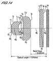
- Fig. 14 is a cross-sectional view of the imaging lens of Embodiment 4.
- the optical length is 1.076 mm, and the back focus is 0.459 mm, so that an adequate length can be secured for the combined focal length f.
- the value of d 3 +d 4 which is the interval between the second surface r 3 of the first lens L 1 and the first surface r 5 of the second lens L 2 , is set to 0.1435 mm, so that a sufficient interval is secured for insertion of the second diaphragm S 2 between the first lens L 1 and second lens L 2 .
- Fig. 15 shows the distortion aberration curve 68
- Fig. 16 shows the astigmatic aberration curves (the aberration curve 70 in the meridional plane and the aberration curve 72 in the sagittal plane)
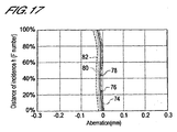
- Fig. 17 shows the chromatic/spherical aberration curves (the aberration curve 74 for the C line, aberration curve 76 for the d line, aberration curve 78 for the e line, aberration curve 80 for the F line, and aberration curve 82 for the g line).
- the vertical axes of the aberration curves in Fig. 15 and Fig. 16 indicate the distance from the optical axis of the image height, as a percentage.
- 100%, 80%, 70%, and 60% on the vertical axes correspond respectively to 0.645 mm, 0.516 mm, 0.451 mm, and 0.387 mm.
- the vertical axis in Fig. 17 indicates the distance of incidence h (F-number); the maximum corresponds to F3.0.
- the horizontal axis in Fig. 17 indicates the aberration magnitude.
- the absolute value of distortion aberration is maximum, at 2.53%, at an image height of 100% (image height 0.645 mm). At image heights of 0.645 mm or less, the absolute value of the aberration is within 2.53%.
- the absolute value of astigmatic aberration is maximum in the meridional plane, at 0.0461 mm, at an image height of 100% (image height 0.645 mm). At image heights of 0.645 mm or less, the absolute value of the aberration is within 0.0461 mm.
- the absolute value of chromatic/spherical aberration is maximum, at 0.0446 mm, for the g line at a distance of incidence h of 100%, and the absolute value of the aberration is everywhere within 0.0446 mm.
- the present invention enables realization of an imaging lens, with various aberrations satisfactorily corrected, and with the ratio of the optical length to the combined focal length of the imaging lens system at most approximately 1.2 (only 1.193 even for the imaging lens of Embodiment 1, for which the ratio was largest), and suitable for use in small-size CCD cameras suited for mounting in portable telephones and similar.
- the ratio of the back focus to the combined focal length of the imaging lens system is also approximately 0.46 (0.454 even for the imaging lens of Embodiment 2, for which the ratio was smallest), so that adequate length could be secured. That is, by means of an imaging lens according to embodiments of the present invention, sufficient back focus length is ensured to enable the insertion of cover glass 12 or other components between the image-side surface r 6 of the second lens L 2 and the image plane, as described in each of the above embodiments of the present invention.
- the value of D 2 /f which is the ratio of the distance between the second surface r 3 of the first lens L 1 and the first surface r 5 of the second lens L 2 to the focal length f for the entire imaging lens system, is set to 0.14 to 0.28 approximately, and is set to 0.1435 even in Embodiments 3 and 4, in which the ratio is set to its smallest value. That is, a sufficient interval is secured for insertion of a second diaphragm S 2 between the first lens L 1 and the second lens L 2 .
- an imaging lens according to embodiments of the present invention can employ lenses formed from material with an Abbe number of 30 to 60, as a result of which cycloolefin plastic or polycarbonate materials can be used as lens materials. Consequently there is no need to use expensive aspherical molded glass, so that low-cost manufacturing becomes possible, and the lens weight can be decreased as well.
- an imaging lens according to embodiments of the present invention can be regarded as suitable for application as a camera lens for incorporation not only in portable telephone sets, personal computers and digital cameras, but also as a camera lens for incorporation into PDAs (personal digital assistants), as a camera lens for embedding in toys comprising image recognition functions, and as a camera lens for incorporation into surveillance, inspection, and crime-prevention equipment.
- PDAs personal digital assistants
Landscapes
- Physics & Mathematics (AREA)
- General Physics & Mathematics (AREA)
- Optics & Photonics (AREA)
- Lenses (AREA)
Claims (4)
- Abbildungslinse mit einer Aperturblende (S1), einer ersten Linse (L1), einer zweiten Blende (S2) und einer zweiten Linse (L2) und wobei
die Abbildungslinse durch Anordnen der Aperturblende (S1), der ersten Linse (L1), der zweiten Blende (S2) und der zweiten Linse (L2) in der Reihenfolge von der Objektseite zu der Bildseite hin eingerichtet ist,
die erste Linse (L1) eine Meniskusform hat, wobei die konvexe Oberfläche zu der Objektseite hin zeigt, und eine positive Brechkraft hat,
die zweite Linse (L2) eine Meniskusform hat, wobei die konvexe Oberfläche zu der Objektseite hin zeigt, und eine positive Brechkraft hat und
beide Oberflächen der ersten Linse (L1) und beide Oberflächen der zweiten Linse (L2) asphärisch sind und die folgenden Bedingungen erfüllen:


wobei f die kombinierte Brennweite der Abbildungslinse ist, f1 die Brennweite der ersten Linse (L1) ist, f2 die Brennweite der zweiten Linse (L2) ist, bf der Abstand (in Luft) von der bildseitigen Oberfläche der zweiten Linse (L2) zu der Bildebene ist, d der Abstand (in Luft) von der objektseitigen Oberfläche der ersten Linse (L1) zu der Bildebene ist, D2 der Abstand zwischen der ersten Linse (L1) und der zweiten Linse (L2) ist und Fno die F-Zahl ist. - Abbildungslinse gemäß Anspruch 1, dadurch gekennzeichnet, daß die erste Linse (L1) und die zweite Linse (L2), welche die Abbildungslinse bilden, aus einem Material mit einer Abbe-Zahl zwischen 30 und 60 gebildet sind.
- Abbildungslinse gemäß Anspruch 1, dadurch gekennzeichnet, daß die erste Linse (L1) und die zweite Linse (L2), welche die Abbildungslinse bilden, aus Cycloolefinplastik- oder Polycarbonatmaterialien gebildet sind.
- Abbildungslinse gemäß Anspruch 2, dadurch gekennzeichnet, daß die erste Linse (L1) und die zweite Linse (L2), welche die Abbildungslinse bilden, aus Cycloolefinplastik- oder Polycarbonatmaterialien gebildet sind.
Applications Claiming Priority (2)
| Application Number | Priority Date | Filing Date | Title |
|---|---|---|---|
| JP2004008966A JP3737095B2 (ja) | 2004-01-16 | 2004-01-16 | 撮像レンズ |
| JP2004008966 | 2004-01-16 |
Publications (2)
| Publication Number | Publication Date |
|---|---|
| EP1555559A1 EP1555559A1 (de) | 2005-07-20 |
| EP1555559B1 true EP1555559B1 (de) | 2006-04-26 |
Family
ID=32709411
Family Applications (1)
| Application Number | Title | Priority Date | Filing Date |
|---|---|---|---|
| EP04253717A Expired - Lifetime EP1555559B1 (de) | 2004-01-16 | 2004-06-22 | Kompaktes Objektiv |
Country Status (6)
| Country | Link |
|---|---|
| US (1) | US7110190B2 (de) |
| EP (1) | EP1555559B1 (de) |
| JP (1) | JP3737095B2 (de) |
| KR (1) | KR100567841B1 (de) |
| CN (1) | CN1333281C (de) |
| DE (1) | DE602004000758T2 (de) |
Families Citing this family (27)
| Publication number | Priority date | Publication date | Assignee | Title |
|---|---|---|---|---|
| JP3753184B1 (ja) * | 2004-10-19 | 2006-03-08 | 株式会社エンプラス | 撮像レンズ |
| JP3753183B1 (ja) * | 2004-10-19 | 2006-03-08 | 株式会社エンプラス | 撮像レンズ |
| JP2007025261A (ja) * | 2005-07-15 | 2007-02-01 | Matsushita Electric Works Ltd | 撮像レンズ |
| KR100703210B1 (ko) | 2005-11-25 | 2007-04-06 | 삼성전기주식회사 | 초소형 촬상 광학계 |
| JP4352044B2 (ja) * | 2005-12-02 | 2009-10-28 | 株式会社エンプラス | 撮像レンズ |
| JP4352043B2 (ja) * | 2005-12-02 | 2009-10-28 | 株式会社エンプラス | 撮像レンズ |
| JP5007536B2 (ja) | 2006-08-02 | 2012-08-22 | ソニー株式会社 | 撮像レンズ系及び撮像装置 |
| KR100838662B1 (ko) * | 2006-10-25 | 2008-06-16 | 현동훈 | 비구면을 이용한 초소형 열감지장치용 광학계 |
| CN101206299B (zh) * | 2006-12-21 | 2011-07-27 | 比亚迪股份有限公司 | 光学镜头组件 |
| CN101414045B (zh) * | 2007-10-18 | 2010-12-08 | 比亚迪股份有限公司 | 一种光学镜头组件 |
| TWI401466B (zh) * | 2009-06-19 | 2013-07-11 | Largan Precision Co | 二片式攝影光學鏡組 |
| CN101937124B (zh) * | 2009-06-30 | 2013-01-30 | 比亚迪股份有限公司 | 一种光学镜头组件 |
| CN102033292B (zh) * | 2009-09-29 | 2012-07-18 | 大立光电股份有限公司 | 二片式摄影光学镜组 |
| WO2011092984A1 (ja) * | 2010-01-27 | 2011-08-04 | コニカミノルタオプト株式会社 | 撮像レンズ、撮像装置及び携帯端末 |
| CN102236155A (zh) * | 2010-04-28 | 2011-11-09 | 夏普株式会社 | 摄像镜头及摄像模块 |
| JP2011248319A (ja) * | 2010-04-28 | 2011-12-08 | Sharp Corp | 撮像レンズおよび撮像モジュール |
| TW201222056A (en) | 2010-11-16 | 2012-06-01 | E Pin Optical Industry Co Ltd | Imaging lens system with two lenses |
| TW201222057A (en) | 2010-11-16 | 2012-06-01 | E Pin Optical Industry Co Ltd | Imaging lens system with two lenses |
| TWI417595B (zh) | 2010-11-24 | 2013-12-01 | Largan Precision Co Ltd | 薄型光學系統 |
| CN102928963A (zh) * | 2011-08-11 | 2013-02-13 | 鸿富锦精密工业(深圳)有限公司 | 取像镜头 |
| US9983663B2 (en) * | 2014-05-16 | 2018-05-29 | Qualcomm Incorporated | Imaging arrangement for object motion detection and characterization |
| TWI607254B (zh) * | 2015-09-25 | 2017-12-01 | 先進光電科技股份有限公司 | 光學成像系統 |
| RU2629888C1 (ru) * | 2016-05-25 | 2017-09-04 | Акционерное общество "Швабе - Оборона и Защита" | Светосильный объектив для инфракрасной области спектра |
| CN106291883B (zh) * | 2016-09-30 | 2019-01-01 | 浙江舜宇光学有限公司 | 摄像镜头及装配有该摄像镜头的摄像装置 |
| TWI766658B (zh) * | 2021-04-23 | 2022-06-01 | 大立光電股份有限公司 | 光學鏡片系統及飛時測距感測模組 |
| CN113176653B (zh) * | 2021-04-28 | 2022-07-01 | 天津欧菲光电有限公司 | 光学系统、镜头模组和电子设备 |
| CN119247594B (zh) * | 2024-10-23 | 2025-10-28 | 成都晶品夜视光电科技有限公司 | 红外镜头及成像装置 |
Family Cites Families (29)
| Publication number | Priority date | Publication date | Assignee | Title |
|---|---|---|---|---|
| FR2522162A1 (fr) * | 1982-02-19 | 1983-08-26 | Defuans Jean Louis | Objectif, notamment pour appareil de prise de vue propre a une surveillance terrestre ou subaquatique |
| JPH07181379A (ja) | 1993-12-24 | 1995-07-21 | Asahi Optical Co Ltd | 結像レンズ系 |
| JPH07281093A (ja) * | 1994-04-11 | 1995-10-27 | Fuji Photo Optical Co Ltd | 簡易型広角ズームレンズ |
| US5739965A (en) * | 1995-05-31 | 1998-04-14 | Fuji Photo Optical Co., Ltd. | Wide angle lens system for camera |
| US6067196A (en) * | 1996-01-16 | 2000-05-23 | Minolta Co., Ltd. | Zoom lens system |
| JP2000075203A (ja) | 1998-08-27 | 2000-03-14 | Fuji Photo Optical Co Ltd | 赤外線レンズ |
| JP2000081568A (ja) | 1998-09-03 | 2000-03-21 | Fuji Photo Optical Co Ltd | アナモフィックアタッチメントレンズ |
| TW484019B (en) * | 1998-12-11 | 2002-04-21 | Minolta Co Ltd | A taking lens system |
| JP2000066096A (ja) | 1999-09-10 | 2000-03-03 | Asahi Optical Co Ltd | 撮像レンズ |
| JP2000066095A (ja) | 1999-09-10 | 2000-03-03 | Asahi Optical Co Ltd | 撮像レンズ |
| JP3311317B2 (ja) | 1999-09-10 | 2002-08-05 | 旭光学工業株式会社 | 撮像レンズ |
| US6441971B2 (en) * | 1999-09-27 | 2002-08-27 | Alex Ning | Compact lens with external aperture stop |
| JP3380533B2 (ja) * | 2000-07-28 | 2003-02-24 | コナミ株式会社 | ゲームシステム、ゲーム制御方法及び情報記憶媒体 |
| JP2002296496A (ja) * | 2001-03-29 | 2002-10-09 | Fuji Photo Optical Co Ltd | 単焦点レンズ |
| JP2003167187A (ja) | 2001-06-20 | 2003-06-13 | Konica Corp | 対物レンズ、光ピックアップ装置及び記録・再生装置 |
| JP2003005055A (ja) | 2001-06-21 | 2003-01-08 | Minolta Co Ltd | 光ピックアップ用対物レンズ |
| JP2003005027A (ja) | 2001-06-21 | 2003-01-08 | Minolta Co Ltd | 光ピックアップ用対物レンズ |
| JP2003005026A (ja) | 2001-06-21 | 2003-01-08 | Minolta Co Ltd | 光ピックアップ用対物レンズ |
| CN1412592A (zh) * | 2001-10-12 | 2003-04-23 | 里程碑株式会社 | 成像透镜 |
| JP3717487B2 (ja) * | 2002-03-29 | 2005-11-16 | フジノン株式会社 | 撮像レンズ |
| JP2003295052A (ja) | 2002-03-29 | 2003-10-15 | Fuji Photo Optical Co Ltd | 赤外線レンズ |
| JP3943988B2 (ja) * | 2002-05-15 | 2007-07-11 | キヤノン株式会社 | レンズ系及びそれを有する光学機器 |
| JP4269334B2 (ja) * | 2002-10-28 | 2009-05-27 | コニカミノルタホールディングス株式会社 | 撮像レンズ、撮像ユニット及び携帯端末 |
| JP2005037764A (ja) * | 2003-07-17 | 2005-02-10 | Olympus Corp | 撮像光学系及びそれを用いた撮像装置 |
| WO2005026804A1 (ja) | 2003-09-09 | 2005-03-24 | Seiko Precision Inc. | 撮影レンズおよび当該撮影レンズを用いた撮像装置 |
| JP4409242B2 (ja) | 2003-09-30 | 2010-02-03 | フジノン株式会社 | 単焦点レンズ |
| JP4423002B2 (ja) | 2003-10-01 | 2010-03-03 | フジノン株式会社 | 単焦点レンズ |
| JP2005107370A (ja) | 2003-10-01 | 2005-04-21 | Fujinon Corp | 結合光学系 |
| JP2005107369A (ja) * | 2003-10-01 | 2005-04-21 | Fujinon Corp | 望遠レンズ |
-
2004
- 2004-01-16 JP JP2004008966A patent/JP3737095B2/ja not_active Expired - Fee Related
- 2004-06-22 DE DE602004000758T patent/DE602004000758T2/de not_active Expired - Fee Related
- 2004-06-22 EP EP04253717A patent/EP1555559B1/de not_active Expired - Lifetime
- 2004-06-23 US US10/873,111 patent/US7110190B2/en not_active Expired - Lifetime
- 2004-07-12 KR KR1020040054158A patent/KR100567841B1/ko not_active Expired - Fee Related
- 2004-07-20 CN CNB2004100713448A patent/CN1333281C/zh not_active Expired - Fee Related
Also Published As
| Publication number | Publication date |
|---|---|
| JP2004177976A (ja) | 2004-06-24 |
| DE602004000758T2 (de) | 2007-02-08 |
| CN1333281C (zh) | 2007-08-22 |
| KR100567841B1 (ko) | 2006-04-05 |
| DE602004000758D1 (de) | 2006-06-01 |
| EP1555559A1 (de) | 2005-07-20 |
| US20050157408A1 (en) | 2005-07-21 |
| JP3737095B2 (ja) | 2006-01-18 |
| CN1641396A (zh) | 2005-07-20 |
| US7110190B2 (en) | 2006-09-19 |
| KR20050075680A (ko) | 2005-07-21 |
Similar Documents
| Publication | Publication Date | Title |
|---|---|---|
| EP1555559B1 (de) | Kompaktes Objektiv | |
| EP1387199B1 (de) | Bildaufnahmeobjektiv | |
| US7675692B2 (en) | Pickup lens | |
| US7408725B2 (en) | Single focus lens | |
| JP3521332B1 (ja) | 撮像レンズ | |
| JP3544972B1 (ja) | 撮像レンズ | |
| US7894141B2 (en) | Imaging lens | |
| KR100555110B1 (ko) | 촬상 렌즈 | |
| EP1868021B1 (de) | Kompaktes Objektiv mit vier Einzellinsen | |
| US7667902B2 (en) | Pickup lens | |
| EP1387198B1 (de) | Bildaufnahmeobjektiv | |
| EP1441248B1 (de) | Objektiv zur Bildaufnahme | |
| EP1785759A1 (de) | Abbildungssystem | |
| JP2002328299A (ja) | 広角撮像用レンズ |
Legal Events
| Date | Code | Title | Description |
|---|---|---|---|
| PUAI | Public reference made under article 153(3) epc to a published international application that has entered the european phase |
Free format text: ORIGINAL CODE: 0009012 |
|
| AK | Designated contracting states |
Kind code of ref document: A1 Designated state(s): AT BE BG CH CY CZ DE DK EE ES FI FR GB GR HU IE IT LI LU MC NL PL PT RO SE SI SK TR |
|
| AX | Request for extension of the european patent |
Extension state: AL HR LT LV MK |
|
| 17P | Request for examination filed |
Effective date: 20050712 |
|
| GRAP | Despatch of communication of intention to grant a patent |
Free format text: ORIGINAL CODE: EPIDOSNIGR1 |
|
| GRAC | Information related to communication of intention to grant a patent modified |
Free format text: ORIGINAL CODE: EPIDOSCIGR1 |
|
| GRAS | Grant fee paid |
Free format text: ORIGINAL CODE: EPIDOSNIGR3 |
|
| GRAA | (expected) grant |
Free format text: ORIGINAL CODE: 0009210 |
|
| AKX | Designation fees paid |
Designated state(s): DE FR GB |
|
| AK | Designated contracting states |
Kind code of ref document: B1 Designated state(s): DE FR GB |
|
| REG | Reference to a national code |
Ref country code: GB Ref legal event code: FG4D |
|
| REF | Corresponds to: |
Ref document number: 602004000758 Country of ref document: DE Date of ref document: 20060601 Kind code of ref document: P |
|
| ET | Fr: translation filed | ||
| PLBE | No opposition filed within time limit |
Free format text: ORIGINAL CODE: 0009261 |
|
| STAA | Information on the status of an ep patent application or granted ep patent |
Free format text: STATUS: NO OPPOSITION FILED WITHIN TIME LIMIT |
|
| 26N | No opposition filed |
Effective date: 20070129 |
|
| PGFP | Annual fee paid to national office [announced via postgrant information from national office to epo] |
Ref country code: DE Payment date: 20090821 Year of fee payment: 6 Ref country code: GB Payment date: 20090616 Year of fee payment: 6 |
|
| GBPC | Gb: european patent ceased through non-payment of renewal fee |
Effective date: 20100622 |
|
| REG | Reference to a national code |
Ref country code: FR Ref legal event code: ST Effective date: 20110228 |
|
| PG25 | Lapsed in a contracting state [announced via postgrant information from national office to epo] |
Ref country code: DE Free format text: LAPSE BECAUSE OF NON-PAYMENT OF DUE FEES Effective date: 20110101 |
|
| PG25 | Lapsed in a contracting state [announced via postgrant information from national office to epo] |
Ref country code: FR Free format text: LAPSE BECAUSE OF NON-PAYMENT OF DUE FEES Effective date: 20100630 |
|
| PG25 | Lapsed in a contracting state [announced via postgrant information from national office to epo] |
Ref country code: GB Free format text: LAPSE BECAUSE OF NON-PAYMENT OF DUE FEES Effective date: 20100622 |
|
| PGFP | Annual fee paid to national office [announced via postgrant information from national office to epo] |
Ref country code: FR Payment date: 20090619 Year of fee payment: 6 |