US6067196A - Zoom lens system - Google Patents
Zoom lens system Download PDFInfo
- Publication number
- US6067196A US6067196A US08/784,177 US78417797A US6067196A US 6067196 A US6067196 A US 6067196A US 78417797 A US78417797 A US 78417797A US 6067196 A US6067196 A US 6067196A
- Authority
- US
- United States
- Prior art keywords
- power
- zoom lens
- lens system
- lens
- diffract light
- Prior art date
- Legal status (The legal status is an assumption and is not a legal conclusion. Google has not performed a legal analysis and makes no representation as to the accuracy of the status listed.)
- Expired - Fee Related
Links
Images


Classifications
-
- G—PHYSICS
- G02—OPTICS
- G02B—OPTICAL ELEMENTS, SYSTEMS OR APPARATUS
- G02B15/00—Optical objectives with means for varying the magnification
- G02B15/14—Optical objectives with means for varying the magnification by axial movement of one or more lenses or groups of lenses relative to the image plane for continuously varying the equivalent focal length of the objective
- G02B15/142—Optical objectives with means for varying the magnification by axial movement of one or more lenses or groups of lenses relative to the image plane for continuously varying the equivalent focal length of the objective having two groups only
- G02B15/1421—Optical objectives with means for varying the magnification by axial movement of one or more lenses or groups of lenses relative to the image plane for continuously varying the equivalent focal length of the objective having two groups only the first group being positive
Definitions
- the present invention relates to a zoom lens system, and particularly to a compact zoom lens system suitable as a taking lens, for example, in a lens-shutter camera.
- zoom lens systems for lens-shutter cameras consist of lens units that are each composed of two or more lens elements.
- it is essential to compose their lens units of as few lens elements as possible.
- U.S. Pat. No. 5,327,290 proposes a zoom lens system consisting of, from the object side, a first lens unit having a positive refractive power and a second lens unit having a negative refractive power.
- each lens unit is composed of two lens elements.
- Japanese Laid-open Patent Application No. H3-15881 proposes a zoom lens system consisting of two lens units, one having a positive refractive power and the other having a negative refractive power.
- the number of lens elements composing each lens unit is reduced by the use of the aspherical surfaces; specifically, the first lens unit is composed of two lens elements, and the second lens unit is composed of as few as one lens element.
- the zoom lens system proposed in these Japanese Laid-open Patent Applications have a defect in that it cannot satisfactorily correct the chromatic aberration over the whole system, because the chromatic aberration within each lens unit cannot be corrected sufficiently at high zooming ratios.
- An object of the present invention is to provide a zoom lens system that, despite being compactly constructed of as few lens elements as possible, is capable of correcting chromatic aberration properly.
- a zoom lens system that includes a lens unit having a negative refractive power disposed at an image-side end and that performs zooming by varying distances between a plurality of lens units
- said plurality of lens units include a surface having a power to diffract light.
- a zoom lens system that comprises, from an object side, a first lens unit having a positive refractive power and a second lens unit having a negative refractive power and that performs zooming from a wide-angle end to a telephoto end by moving the first and second lens units in such a way that a distance between the first and second lens units decreases
- said zoom lens system includes at least one surface having a power to diffract light.
- said first lens unit is composed of at least two lens elements, and said zoom lens system includes at least one surface having a power to diffract light.
- said second lens unit is composed of one lens element.
- said first lens unit is composed of one lens element
- said second lens unit is composed of at least two lens elements
- said zoom lens system includes at least one surface having a power to diffract light
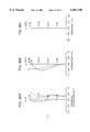
- FIG. 1 is a diagram showing the lens construction of the zoom lens system of the first embodiment of the present invention
- FIG. 2 is a diagram showing the lens construction of the zoom lens system of the second embodiment of the present invention.
- FIG. 3 is a diagram showing the lens construction of the zoom lens system of the third embodiment of the present invention.
- FIG. 4 is a diagram showing the lens construction of the zoom lens system of the fourth embodiment of the present invention.
- FIG. 5 is a diagram showing the lens construction of the zoom lens system of the fifth embodiment of the present invention.
- FIG. 6 is a diagram showing the lens construction of the zoom lens system of the sixth embodiment of the present invention.
- FIG. 7 is a diagram showing the lens construction of the zoom lens system of the seventh embodiment of the present invention.
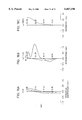
- FIGS. 8A, 8B, and 8C are diagrams showing the aberration at the wide-angle end in the first embodiment
- FIGS. 9A, 9B, and 9C are diagrams showing the aberration at the middle focal length in the first embodiment
- FIGS. 10A, 10B, and 10C are diagrams showing the aberration at the telephoto end in the first embodiment
- FIGS. 11A, 11B, and 11C are diagrams showing the aberration at the wide-angle end in the second embodiment
- FIGS. 12A, 12B, and 12C are diagrams showing the aberration at the middle focal length in the second embodiment
- FIGS. 13A, 13B, and 13C are diagrams showing the aberration at the telephoto end in the second embodiment
- FIGS. 14A, 14B, and 14C are diagrams showing the aberration at the wide-angle end in the third embodiment
- FIGS. 15A, 15B, and 15C are diagrams showing the aberration at the middle focal length in the third embodiment
- FIGS. 16A, 16B, and 16C are diagrams showing the aberration at the telephoto end in the third embodiment
- FIGS. 17A, 17B, and 17C are diagrams showing the aberration at the wide-angle end in the fourth embodiment
- FIGS. 18A, 18B, and 18C are diagrams showing the aberration at the middle focal length in the fourth embodiment
- FIGS. 19A, 19B, and 19C are diagrams showing the aberration at the telephoto end in the fourth embodiment
- FIGS. 20A, 20B, and 20C are diagrams showing the aberration at the wide-angle end in the fifth embodiment
- FIGS. 21A, 21B, and 21C are diagrams showing the aberration at the middle focal length in the fifth embodiment
- FIGS. 22A, 22B, and 22C are diagrams showing the aberration at the telephoto end in the fifth embodiment
- FIGS. 23A, 23B, and 23C are diagrams showing the aberration at the wide-angle end in the sixth embodiment.
- FIGS. 24A, 24B, and 24C are diagrams showing the aberration at the middle focal length in the sixth embodiment.
- FIGS. 25A, 25B, and 25C are diagrams showing the aberration at the telephoto end in the sixth embodiment
- FIGS. 26A, 26B, and 26C are diagrams showing the aberration at the wide-angle end in the seventh embodiment
- FIGS. 27A, 27B, and 27C are diagrams showing the aberration at the middle focal length in the seventh embodiment
- FIGS. 28A, 28B, and 28C are diagrams showing the aberration at the telephoto end in the seventh embodiment
- FIG. 29 is a diagram showing the lens construction of the zoom lens system of the eighth embodiment of the present invention.
- FIG. 30 is a diagram showing the lens construction of the zoom lens system of the ninth embodiment of the present invention.
- FIG. 31 is a diagram showing the lens construction of the zoom lens system of the tenth embodiment of the present invention.
- FIG. 32 is a diagram showing the lens construction of the zoom lens system of the eleventh embodiment of the present invention.
- FIG. 33 is a diagram showing the lens construction of the zoom lens system of the twelfth embodiment of the present invention.
- FIGS. 34A, 34B, and 34C are diagrams showing the aberration at the wide-angle end in the eighth embodiment.
- FIGS. 35A, 35B, and 35C are diagrams showing the aberration at the middle focal length in the eighth embodiment.
- FIGS. 36A, 36B, and 36C are diagrams showing the aberration at the telephoto end in the eighth embodiment
- FIGS. 37A, 37B, and 37C are diagrams showing the aberration at the wide-angle end in the ninth embodiment.
- FIGS. 38A, 38B, and 38C are diagrams showing the aberration at the middle focal length in the ninth embodiment.
- FIGS. 39A, 39B, and 39C are diagrams showing the aberration at the telephoto end in the ninth embodiment.
- FIGS. 40A, 40B, and 40C are diagrams showing the aberration at the wide-angle end in the tenth embodiment
- FIGS. 41A, 41B, and 41C are diagrams showing the aberration at the middle focal length in the tenth embodiment
- FIGS. 42A, 42B, and 42C are diagrams showing the aberration at the telephoto end in the tenth embodiment
- FIGS. 43A, 43B, and 43C are diagrams showing the aberration at the wide-angle end in the eleventh embodiment.
- FIGS. 44A, 44B, and 44C are diagrams showing the aberration at the middle focal length in the eleventh embodiment
- FIGS. 45A, 45B, and 45C are diagrams showing the aberration at the telephoto end in the eleventh embodiment
- FIGS. 46A, 46B, and 46C are diagrams showing the aberration at the wide-angle end in the twelfth embodiment
- FIGS. 47A, 47B, and 47C are diagrams showing the aberration at the middle focal length in the twelfth embodiment
- FIGS. 48A, 48B, and 48C are diagrams showing the aberration at the telephoto end in the twelfth embodiment
- FIG. 49 is a diagram showing the lens construction of the zoom lens system of the thirteenth embodiment of the present invention.
- FIG. 50 is a diagram showing the lens construction of the zoom lens system of the fourteenth embodiment of the present invention.
- FIG. 51 is a diagram showing the lens construction of the zoom lens system of the fifteenth embodiment of the present invention.
- FIG. 52 is a diagram showing the lens construction of the zoom lens system of the sixteenth embodiment of the present invention.
- FIG. 53 is a diagram showing the lens construction of the zoom lens system of the seventeenth embodiment of the present invention.
- FIG. 54 is a diagram showing the lens construction of the zoom lens system of the eighteenth embodiment of the present invention.
- FIGS. 55A, 55B, and 55C are diagrams showing the aberration at the wide-angle end in the thirteenth embodiment
- FIGS. 56A, 56B, and 56C are diagrams showing the aberration at the middle focal length in the thirteenth embodiment
- FIGS. 57A, 57B, and 57C are diagrams showing the aberration at the telephoto end in the thirteenth embodiment
- FIGS. 58A, 58B, and 58C are diagrams showing the aberration at the wide-angle end in the fourteenth embodiment
- FIGS. 59A, 59B, and 59C are diagrams showing the aberration at the middle focal length in the fourteenth embodiment
- FIGS. 60A, 60B, and 60C are diagrams showing the aberration at the telephoto end in the fourteenth embodiment
- FIGS. 61A, 61B, and 61C are diagrams showing the aberration at the wide-angle end in the fifteenth embodiment
- FIGS. 62A, 62B, and 62C are diagrams showing the aberration at the middle focal length in the fifteenth embodiment
- FIGS. 63A, 63B, and 63C are diagrams showing the aberration at the telephoto end in the fifteenth embodiment
- FIGS. 64A, 64B, and 64C are diagrams showing the aberration at the wide-angle end in the sixteenth embodiment
- FIGS. 65A, 65B, and 65C are diagrams showing the aberration at the middle focal length in the sixteenth embodiment
- FIGS. 66A, 66B, and 66C are diagrams showing the aberration at the telephoto end in the sixteenth embodiment
- FIGS. 67A, 67B, and 67C are diagrams showing the aberration at the wide-angle end in the seventeenth embodiment
- FIGS. 68A, 68B, and 68C are diagrams showing the aberration at the middle focal length in the seventeenth embodiment
- FIGS. 69A, 69B, and 69C are diagrams showing the aberration at the telephoto end in the seventeenth embodiment
- FIGS. 70A, 70B, and 70C are diagrams showing the aberration at the wide-angle end in the eighteenth embodiment
- FIGS. 71A, 71B, and 71C are diagrams showing the aberration at the middle focal length in the eighteenth embodiment
- FIGS. 72A, 72B, and 72C are diagrams showing the aberration at the telephoto end in the eighteenth embodiment
- FIG. 73 is a diagram showing the lens construction of the zoom lens system of the nineteenth embodiment of the present invention.
- FIG. 74 is a diagram showing the lens construction of the zoom lens system of the twentieth embodiment of the present invention.
- FIG. 75 is a diagram showing the lens construction of the zoom lens system of the twenty-first embodiment of the present invention.
- FIGS. 76A, 76B, and 76C are diagrams showing the aberration at the wide-angle end in the nineteenth embodiment
- FIGS. 77A, 77B, and 77C are diagrams showing the aberration at the middle focal length in the nineteenth embodiment
- FIGS. 78A, 78B, and 78C are diagrams showing the aberration at the telephoto end in the nineteenth embodiment
- FIGS. 79A, 79B, and 79C are diagrams showing the aberration at the wide-angle end in the twentieth embodiment
- FIGS. 80A, 80B, and 80C are diagrams showing the aberration at the middle focal length in the twentieth embodiment
- FIGS. 81A, 81B, and 81C are diagrams showing the aberration at the telephoto end in the twentieth embodiment
- FIGS. 82A, 82B, and 82C are diagrams showing the aberration at the wide-angle end in the twenty-first embodiment
- FIGS. 83A, 83B, and 83C are diagrams showing the aberration at the middle focal length in the twenty-first embodiment.
- FIGS. 84A, 84B, and 84C are diagrams showing the aberration at the telephoto end in the twenty-first embodiment.
- the zoom lens system of the present invention will be described with reference to the drawings.
- the power with which a diffractive optical element diffracts light is referred to as the power of the diffractive optical element
- the composition of the power with which a diffractive optical element diffracts light and the refractive powers of individual refractive optical surfaces is referred to as the composite power of the diffractive optical element and the refractive optical surfaces.
- the zoom lens systems of the first to twenty-first embodiments of the present invention will be described below.
- the zoom lens system of each embodiment is constituted of, from the object side, a first lens unit Gr1 having a positive refractive power and a second lens unit Gr2 having a negative refractive power.
- the first and second lens units Gr1 and Gr2 are moved in such a way that the distance between them decreases.
- the arrows m1 and m2 schematically show the directions in which the first and second lens units Gr1 and Gr2 are respectively moved during zooming from the wide-angle end (W) to the telephoto end (T).
- FIGS. 1 to 7 show the lens constructions of the zoom lens systems of the first to seventh embodiments. Each figure shows the lens construction at the wide-angle end (W).
- a surface ri marked with an asterisk (*) is an aspherical surface
- a surface ri marked with [DOE] is a diffractive optical surface.
- the zoom lens system of the first embodiment is constituted of, from the object side, a first lens unit Gr1 composed of a light-shielding member F, an aperture diaphragm A, and a positive meniscus lens element L1 (having aspherical surfaces on both sides and a diffractive optical element on the image-surface side) with its concave surface facing toward the object side, and a second lens unit Gr2 composed only of a negative meniscus lens element L2 (having aspherical surfaces on both sides and a diffractive optical element on the image-surface side) with its convex surface facing toward the object side.
- the zoom lens system of the second embodiment is constituted of, from the object side, a first lens unit Gr1 composed of a light-shielding member F, an aperture diaphragm A, and a positive meniscus lens element L1 (having aspherical surfaces on both sides and a diffractive optical element on the image-surface side) with its concave surface facing toward the object side, and a second lens unit Gr2 composed only of a negative meniscus lens element L2 (having aspherical surfaces on both sides and a diffractive optical element on the image-surface side) with its convex surface facing toward the object side.
- the zoom lens system of the third embodiment is constituted of, from the object side, a first lens unit Gr1 composed of a light-shielding member F, an aperture diaphragm A, and a positive meniscus lens element L1 (having aspherical surfaces on both sides and a diffractive optical element on the image-surface side) with its concave surface facing toward the object side, and a second lens unit Gr2 composed only of a negative meniscus lens element L2 (having aspherical surfaces on both sides and a diffractive optical element on the image-surface side) with its convex surface facing toward the object side.
- the zoom lens system of the fourth embodiment is constituted of, from the object side, a first lens unit Gr1 composed of a light-shielding member F, an aperture diaphragm A, and a positive meniscus lens element L1 (having aspherical surfaces on both sides and a diffractive optical element on the image-surface side) with its concave surface facing toward the object side, and a second lens unit Gr2 composed only of a negative meniscus lens element L2 (having aspherical surfaces on both sides and a diffractive optical element on the image-surface side) with its convex surface facing toward the object side.
- the zoom lens system of the fifth embodiment is constituted of, from the object side, a first lens unit Gr1 composed of a light-shielding member F, an aperture diaphragm A, and a positive meniscus lens element L1 (having aspherical surfaces on both sides and a diffractive optical element on the image-surface side) with its concave surface facing toward the object side, and a second lens unit Gr2 composed only of a negative meniscus lens element L2 (having aspherical surfaces on both sides) with its convex surface facing toward the object side.
- the zoom lens system of the sixth embodiment is constituted of, from the object side, a first lens unit Gr1 composed of a light-shielding member F, an aperture diaphragm A, and a positive meniscus lens element L1 (having aspherical surfaces on both sides and a diffractive optical element on the image-surface side) made of plastics with its concave surface facing toward the object side, and a second lens unit Gr2 composed only of a negative meniscus lens element L2 (having aspherical surfaces on both sides and a diffractive optical element on the image-surface side) made of plastics with its convex surface facing toward the object side.
- the zoom lens system of the seventh embodiment is constituted of, from the object side, a first lens unit Gr1 composed of a light-shielding member F, an aperture diaphragm A, and a positive meniscus lens element L1 (having aspherical surfaces on both sides and a diffractive optical element on the image-surface side) with its concave surface facing toward the object side, and a second lens unit Gr2 composed only of a biconcave lens element L2 (having aspherical surfaces on both sides and a diffractive optical element on the image-surface side) made of plastics.
- the zoom lens systems of the first to seventh embodiments are designed to be a telephoto-oriented zoom lens system by arranging a negative lens unit at the image-surface-side end. As a result, it is possible to realize a compact zoom lens system with a relatively short total length at the telephoto end.
- the zoom lens systems of the first to seventh embodiments are provided with a diffractive optical element.
- the use of at least one diffractive optical element in a zoom lens system makes it possible to properly correct chromatic aberration, which is difficult to correct in a conventional zoom lens system composed solely of refractive optical elements when the number of optical elements is reduced to a minimum.
- FIGS. 29 to 33 show the lens constructions of the zoom lens systems of the eighth to twelfth embodiments. Each figure shows the lens construction at the wide-angle end (W).
- a surface ri marked with an asterisk (*) is an aspherical surface
- a surface ri marked with [DOE] is a diffractive optical surface.
- the zoom lens system of the eighth embodiment is constituted of, from the object side, a first lens unit Gr1 composed of a first lens element L1 (having aspherical surfaces on both sides) that is a negative meniscus lens with its concave surface facing toward the object side, a second lens element L2 that is a biconvex lens, and an aperture diaphragm A, and a second lens unit Gr2 composed of a third lens element L3 (having aspherical surfaces on both sides and a diffractive optical element on the object side, and made of plastics) that is a positive meniscus lens with its convex surface facing toward the image side, and a fourth lens element L4 that is a negative meniscus lens with its concave surface facing toward the object side.
- the zoom lens system of the ninth embodiment is constituted of, from the object side, a first lens unit Gr1 composed of a first lens element L1 (having aspherical surfaces on both sides and a diffractive optical element on the object side) that is a negative meniscus lens with its convex surface facing toward the object side, a second lens element L2 that is a positive meniscus lens with its convex surface facing toward the image side, and an aperture diaphragm A, and a second lens unit Gr2 composed of a third lens element L3 (having aspherical surfaces on both sides) that is a positive meniscus lens with its convex surface facing toward the image side, and a fourth lens element L4 that is a negative meniscus lens with its concave surface facing toward the object side.
- a first lens unit Gr1 composed of a first lens element L1 (having aspherical surfaces on both sides and a diffractive optical element on the object side) that is a negative meniscus lens with its convex surface facing toward the object side,
- the zoom lens system of the tenth embodiment is constituted of, from the object side, a first lens unit Gr1 composed of a first lens element L1 (having aspherical surfaces on both sides) that is a negative meniscus lens with its convex surface facing toward the object side, a second lens element L2 (having a diffractive optical element on the image-surface side, and made of plastics) that is a biconvex lens, and an aperture diaphragm A, and a second lens unit Gr2 composed of a third lens element L3 (having aspherical surfaces on both sides and a diffractive optical element on the object side) that is a positive meniscus lens with its convex surface facing toward the image side, and a fourth lens element L4 that is a negative meniscus lens with its concave surface facing toward the object side.
- a first lens unit Gr1 composed of a first lens element L1 (having aspherical surfaces on both sides) that is a negative meniscus lens with its convex surface facing toward the
- the zoom lens system of the eleventh embodiment is constituted of, from the object side, a first lens unit Gr1 composed of a first lens element L1 (having an aspherical surface on the object side and a diffractive optical element on the object side) that is a negative meniscus lens with its convex surface facing toward the object side, a second lens element L2 that is a biconvex lens, and an aperture diaphragm A, and a second lens unit Gr2 composed of a third lens element L3 (having an aspherical surface on the image side) that is a positive meniscus lens with its convex surface facing toward the image side, and a fourth lens element L4 that is a negative meniscus lens with its concave surface facing toward the object side.
- a first lens unit Gr1 composed of a first lens element L1 (having an aspherical surface on the object side and a diffractive optical element on the object side) that is a negative meniscus lens with its convex surface facing toward the object side
- the zoom lens system of the twelfth embodiment is constituted of, from the object side, a first lens unit Gr1 composed of a first lens element L1 (having aspherical surfaces on both sides) that is a negative meniscus lens with its convex surface facing toward the object side, a second lens element L2 (having a diffractive optical element on the image side) that is a biconvex lens, and an aperture diaphragm, and a second lens unit Gr2 composed of a third lens element L3 (having aspherical surfaces on both sides) that is a positive meniscus lens with its convex surface facing toward the image side, and a fourth lens element L4 (having a diffractive optical element on the image side) that is a negative meniscus lens with its concave surface facing toward the object side.
- a first lens unit Gr1 composed of a first lens element L1 (having aspherical surfaces on both sides) that is a negative meniscus lens with its convex surface facing toward the object side,
- the first lens unit Gr1 is composed of two lens elements.
- the first lens unit Gr1 is composed of at least two lens elements, it is possible to properly correct off-axial coma aberration, which occurs in the first lens unit Gr1 when the whole system is adapted to high magnifications.
- the zoom lens systems of the eighth to twelfth embodiments are each provided with a diffractive optical element.
- the use of at least one diffractive optical element in a zoom lens system makes it possible to properly correct chromatic aberration, which is difficult to correct in a conventional zoom lens system composed solely of refractive optical surfaces.
- FIGS. 49 to 54 show the lens constructions of the zoom lens systems of the thirteenth to eighteenth embodiments. Each figure shows the lens construction at the wide-angle end (W).
- a surface ri marked with an asterisk (*) is an aspherical surface
- a surface ri marked with [DOE] is a diffractive optical surface.
- the first lens unit Gr1 is composed of, from the object side, a negative meniscus lens element (having aspherical surfaces on both sides and a diffractive optical element on the image side) with its convex surface facing toward the object side, a biconvex positive lens element, and an aperture diaphragm A.
- the second lens unit Gr2 is composed of a negative meniscus lens element (having aspherical surfaces on both sides) with its convex surface facing toward the image side.
- the first lens unit Gr1 is composed of, from the object side, a negative meniscus lens element (having aspherical surfaces on both sides and a diffractive optical element on the image side) with its convex surface facing toward the object side, a positive meniscus lens element with its concave surface facing toward the object side, and an aperture diaphragm A.
- the second lens unit Gr2 is composed of a negative meniscus lens element (having aspherical surfaces on both sides and a diffractive optical element on the object side) with its convex surface facing toward the image side.
- the first lens unit Gr1 is composed of, from the object side, a negative meniscus lens element (having aspherical surfaces on both sides) with its convex surface facing toward the object side, a positive meniscus lens element with its concave surface facing toward the object side, and an aperture diaphragm A.
- the second lens unit Gr2 is composed of a negative meniscus lens element (having aspherical surfaces on both sides and a diffractive optical element on the object side) with its convex surface facing toward the image side.
- the first lens unit Gr1 is composed of, from the object side, a negative meniscus lens element (having aspherical surfaces on both sides) with its concave surface facing toward the object side, a biconvex positive lens element, and an aperture diaphragm A.
- the second lens unit Gr2 is composed of a negative meniscus lens element (having aspherical surfaces on both sides and a diffractive optical element on the object side) with its convex surface facing toward the image side.
- the first lens unit Gr1 is composed of, from the object side, a negative meniscus lens element (having aspherical surfaces on both sides) with its concave surface facing toward the object side, a positive meniscus lens element (having a diffractive optical element on the image side) with its concave surface facing toward the object side, and an aperture diaphragm A.
- the second lens unit Gr2 is composed of a negative meniscus lens element (having aspherical surfaces on both sides) with its convex surface facing toward the image side.
- the first lens unit Gr1 is composed of two lens elements.
- the first lens unit Gr1 is composed of at least two lens elements, it is possible to properly correct the off-axial coma aberration occurring in the first lens unit Gr1.
- the second lens unit Gr2 is composed of one lens element, such reduction in the number of lens elements does not result here in undercorrection of chromatic aberration as experienced in a conventional zoom lens system composed solely of refractive optical surfaces. This is because the use of at least one diffractive optical element within the whole zoom lens system makes it possible to properly correct chromatic aberration.
- the only lens composing the second lens unit Gr2 may be either a single lens or doublet lens.
- FIGS. 73 to 75 show the lens constructions of the zoom lens systems of the nineteenth to twenty-first embodiments. Each figure shows the lens construction at the wide-angle end (W).
- a surface ri marked with an asterisk (*) is an aspherical surface
- a surface ri marked with [DOE] is a diffractive optical surface.
- the first lens unit Gr1 is composed of, from the object side, a positive meniscus lens element (having aspherical surfaces on both sides and a diffractive optical element on the image side) with its concave surface facing toward the object side, and an aperture diaphragm A.
- the second lens unit Gr2 is composed of, from the object side, a positive meniscus lens element (having aspherical surfaces on both sides) with its convex surface facing toward the image side, and a negative meniscus lens element with its concave surface facing toward the object side.
- the first lens unit Gr1 is composed of, from the object side, a positive meniscus lens element (having aspherical surfaces on both sides and a diffractive optical element on the image side) with its concave surface facing toward the object side, and an aperture diaphragm A.
- the second lens unit Gr2 is composed of, from the object side, a positive meniscus lens element (having aspherical surfaces on both sides and a diffractive optical element on the image side) with its convex surface facing toward the image side, and a negative meniscus lens element with its concave surface facing toward the object side.
- the first lens unit Gr1 is composed of one lens element
- the second lens unit Gr2 is composed of two lens elements.
- Composing the first lens unit Gr1 of one lens element makes it possible to simplify the construction of the lens barrel, and also to reduce the size and cost of the zoom lens system.
- Composing the second lens unit Gr2 of at least two lens elements makes it possible to properly correct off-axial coma aberration.
- the first lens unit Gr1 is composed of one lens element, such reduction in the number of lens elements does not result here in undercorrection of chromatic aberration as experienced in a conventional zoom lens system composed solely of refractive optical surfaces. This is because the use of at least one diffractive optical element within the whole zoom lens system makes it possible to properly correct chromatic aberration.
- the only lens composing the first lens unit Gr1 may be either a single lens or doublet lens.
- axial chromatic aberration as dealt with in a thin-lens system, is defined by the following formula:
- ⁇ r refractive power of the refractive optical surface
- ⁇ r dispersion of the refractive optical surface (i.e. Abbe number);
- ⁇ doe power of the diffractive optical element
- ⁇ doe dispersion of the diffractive optical element (i.e. the value corresponding to the Abbe number).
- Nd refractive index of the refractive optical surface on the lens optical axis, with d-lines
- Nf refractive index of the refractive optical surface on the lens optical axis, with f-lines
- Nc refractive index of the refractive optical surface on the lens optical axis, with c-lines
- ⁇ d wavelength of d-lines
- ⁇ f wavelength of f-lines
- ⁇ c wavelength of c-lines.
- Formula (C) above shows that a diffractive optical element has a large negative value of dispersion (-3.45).
- a diffractive optical element in combination with a refractive optical surface, the positive ⁇ r/ ⁇ r is canceled out by the negative ⁇ doe/ ⁇ doe, and thus the chromatic aberration occurring in the refractive optical surface is corrected by the diffractive optical element.
- the zoom lens systems of the first to twenty-first embodiments take advantage of this property of a diffractive optical element to correct chromatic aberration, by correcting the chromatic aberration occurring in a refractive optical element having a refractive optical surface by means of a diffractive optical element having a diffractive optical surface.
- a diffractive optical element is provided on a refractive optical surface (as a hybrid diffractive-refractive lens element). Accordingly, the chromatic aberration occurring on the refractive optical surface can be properly corrected by the diffractive optical element. Moreover, the zoom lens systems of the first to twenty-first embodiments can be made compact, since they need no additional lens element for correcting chromatic aberration.
- a diffractive optical element be provided on a refractive optical surface having an aspherical shape.
- the use of an aspherical surface as a base surface on which a diffractive optical element is provided allows the aspherical surface and the diffractive optical element to be shaped simultaneously when, for example, the diffractive optical element is formed by machining. This not only leads to reduction of production time, but also permits high-precision machining. Therefore, providing a diffractive optical element on a refractive optical surface is highly effective in terms of production.
- the phase shape of a diffractive optical element can be freely designed, and therefore it is possible to design a diffractive optical element that is optically equivalent to an aspherical surface on a refractive optical surface. Accordingly, not only chromatic aberration but also spherical aberration can be corrected with a diffractive optical element.
- spherical aberration is corrected solely with the phase shape of a diffractive optical element, the spherical aberration for light having a design wavelength is corrected, but, since light having wavelengths different from the design value is diffracted differently, spherical aberration of color becomes rather greater. For this reason, it is preferable to correct spherical aberration with a refractive optical surface.
- spherical aberration and off-axial coma aberration are corrected properly with an aspherical surface of a refractive optical surface, whereas axial chromatic aberration and chromatic aberration of magnification are corrected with a diffractive optical element provided on a refractive optical surface, so that satisfactory optical performance is obtained.
- the diffractive optical element be blazed (saw-toothed).
- a blazed diffractive optical element it is possible to obtain better diffraction efficiency.
- a blazed diffractive optical element can be produced by approximating the saw-toothed shape as a stepped shape in a manner similar to a semiconductor production technique (binary optics), or by molding glass or a plastic material with a mold produced through precision machining, or by molding a resin layer formed on the surface of a glass lens into a diffractive optical element.
- a diffractive optical element is arranged in the second lens unit.
- the use of at least one diffractive optical element in the negative lens unit that is disposed at the image-surface-side end makes it possible to properly correct the chromatic aberration of magnification occurring in the object-side lens unit.
- a diffractive optical element is arranged in the first lens unit having a positive refractive power.
- the use of at least one diffractive optical element in the lens unit that is disposed at the object-side end makes it possible to properly correct the axial chromatic aberration occurring in the object-side lens unit having a positive refractive power as a whole.
- the zoom lens systems of the sixth and seventh embodiments have a diffractive optical element provided on a plastic lens element, and therefore these zoom lens systems can be produced with especially reduced cost.
- the zoom lens systems of the first to seventh embodiments is constituted of, from the object side, a first lens unit having a positive refractive power and a second lens unit having a negative refractive power, and, during zooming from the wide-angle end to the telephoto end, the first and second lens units are moved in such a way that the distance between them decreases.
- adoption of a two-lens-unit construction constituted of the positive and negative lens units helps produce a compact zoom lens system with satisfactory optical performance.
- the use of a diffractive optical element in a zoom lens system constituted of two positive and negative lens units makes it possible to properly correct chromatic aberration, which cannot be corrected satisfactorily with refractive optical surfaces alone, and also to reduce the number of lens elements needed.
- zoom lens systems of the first to seventh embodiments satisfy the following conditional expression (1):
- ⁇ doe power of the diffractive optical element
- ⁇ r composite power of the diffractive optical element and the refractive optical surface.
- conditional expression (1) If the upper limit of conditional expression (1) is exceeded, the power of the diffractive optical element within the lens unit is too strong, with the result that chromatic aberration is overcorrected by the diffractive optical element. By contrast, if the lower limit of conditional expression (1) is exceeded, the power of the diffractive optical element within the lens unit is too weak, with the result that chromatic aberration is undercorrected by the diffractive optical element.
- R 2 secondary phase coefficient of the diffractive optical element
- H max effective diameter of the diffractive optical element
- conditional expression (2) If the lower limit of conditional expression (2) is exceeded, the correction of chromatic aberration by the diffractive optical element is insufficient, and accordingly it is difficult to correct chromatic aberration properly.
- the upper limit of conditional expression (2) if the upper limit of conditional expression (2) is exceeded, not only the correction of chromatic aberration is excessive, but also the pitch of the diffractive optical element at its periphery becomes too small to obtain sufficient diffraction effects.
- the upper limit of conditional expression (2) is exceeded, and accordingly the pitch of the diffractive optical element becomes smaller, the diffractive optical element becomes more difficult to produce.
- zoom lens systems of the first to seventh embodiments satisfy the following conditional expression (3):
- ⁇ Gr1 composite power of the first lens unit
- ⁇ Gr2 composite power of the second lens unit.
- the effective diameter of the second lens unit is generally greater than that of the first lens unit. Accordingly, in attempting to reduce the cost of the zoom lens system constituted of two positive and negative lens units by providing it with a diffractive optical element, it is more effective to provide the diffractive optical element only in the first lens unit, which has the smaller effective diameter. In the zoom lens system of the fifth embodiment, a diffractive optical element is provided only in the first lens unit. This further reduces the production cost.
- ⁇ 21 dispersion of the refractive optical surface of the second lens unit.
- the second lens unit is composed of one lens element having only refractive optical surfaces, it is nearly impossible to correct chromatic aberration within the lens unit.
- conditional expression (4) chromatic aberration can be corrected properly over the whole lens system. If the dispersion is so great that the lower limit of conditional expression (4) is exceeded, the chromatic aberration of magnification occurring in the second lens unit is too great to correct properly.
- a diffractive optical element is provided in the second lens unit Gr2.
- the use of at least one diffractive optical element in the negative lens unit that is disposed at the image-surface-side end makes it possible to properly correct the chromatic aberration of magnification occurring in the object-side lens unit.
- the use of at least one diffractive optical element in a negative lens unit makes it possible to properly correct axial chromatic aberration.
- a diffractive optical element is provided on the object-side surface of the first lens element L1.
- a diffractive optical element at the object-side end where light paths vary greatly with the angle of view, makes it possible to properly correct axial chromatic aberration and off-axial chromatic aberration of magnification.
- a diffractive optical element is arranged on the object-side surface of the third lens element L3.
- the zoom lens systems of the eighth and tenth embodiments have a diffractive optical element formed on their third, plastic, lens element L3, and therefore these zoom lens systems can be produced with especially reduced cost.
- the use of a blazed diffractive optical element causes degradation of diffraction efficiency because, as the angle of incidence becomes greater, the apparent pitch of the diffractive optical element as seen from the direction of incidence becomes smaller.
- this problem can be alleviated by disposing the diffractive optical element at the image-side end of a lens unit.
- a diffracting optical element is provided at the image-surface-side end of the first lens unit Gr1 as in the tenth and twelfth embodiments, the angle of incidence of light rays striking the diffractive optical element becomes smaller than at the object-side surface of the same lens, and thus degradation of diffraction efficiency is suppressed.
- zoom lens systems of the eighth to twelfth embodiments satisfy the following conditional expression (5):
- ⁇ doe power of the diffractive optical element
- ⁇ r composite power of the diffractive optical element and the refractive optical surface.
- conditional expression (5) If the upper limit of conditional expression (5) is exceeded, the power of the diffractive optical element within the lens unit is too strong, with the result that chromatic aberration is overcorrected by the diffractive optical element. By contrast, if the lower limit of conditional expression (5) is exceeded, the power of the diffractive optical element within the lens unit is too weak, with the result that chromatic aberration is undercorrected by the diffractive optical element.
- R 2 secondary phase coefficient of the diffractive optical element
- conditional expression (6) If the lower limit of conditional expression (6) is exceeded, the correction of chromatic aberration by the diffractive optical element is insufficient, and accordingly it is difficult to correct chromatic aberration properly.
- the upper limit of conditional expression (6) is exceeded, not only the correction of chromatic aberration is excessive, but also the pitch of the diffractive optical element at its periphery becomes too small to obtain sufficient diffraction effects. In addition, as the pitch of the diffractive optical element becomes smaller, the diffractive optical element becomes more difficult to produce.
- the second lens unit Gr2 with at least one diffractive optical element.
- the use of at least one diffractive optical element in the second lens unit Gr2 makes it possible, even if the second lens unit Gr2 is composed of one lens element, to properly correct the chromatic aberration occurring in the second lens unit Gr2 and thus to reduce the chromatic aberration occurring during zooming.
- the first lens unit Gr1 with at least one diffractive optical element.
- the use of at least one diffractive optical element in the first lens unit Gr1 makes it possible to properly correct axial chromatic aberration.
- each lens unit that is provided with a diffractive optical element satisfy the following conditional expression (7):
- ⁇ doe power of the diffractive optical element
- ⁇ r composite power of the diffractive optical element and the refractive optical surface.
- conditional expression (7) If the upper limit of conditional expression (7) is exceeded, the power of the diffractive optical element within the lens unit is too strong, with the result that chromatic aberration is overcorrected by the diffractive optical element. By contrast, if the lower limit of conditional expression (7) is exceeded, the power of the diffractive optical element within the lens unit is too weak, with the result that chromatic aberration is undercorrected by the diffractive optical element.
- conditional expression (8) which is the same as the above-described conditional expression (2), be satisfied:
- Conditional expression (8) defines the range of conditions to be preferably satisfied in the production of the diffractive optical element. If the lower limit of conditional expression (8) is exceeded, the correction of chromatic aberration by the diffractive optical element is insufficient, and accordingly it is difficult to correct chromatic aberration properly. By contrast, if the upper limit of conditional expression (8) is exceeded, not only the correction of chromatic aberration is excessive, but also the pitch of the diffractive optical element at its periphery becomes too small to obtain sufficient diffraction effects. In addition, as the pitch of the diffractive optical element becomes smaller, the diffractive optical element becomes more difficult to produce.
- a zoom lens system consisting of two, positive and negative, lens units, such as the thirteenth, fourteenth, and eighteenth embodiments described above, in which at least one diffractive optical element is provided in the first lens unit Gr1 and in which, during zooming from the wide-angle end (W) to the telephoto end (T), a first lens unit Gr1 composed of at least two lens elements and a second lens unit Gr2 composed of one lens are moved in such a way that the distance (d5) between them decreases, it is desirable that the following expression (9) be satisfied:
- ⁇ doe1 power of the diffractive optical element provided in the first lens unit Gr1;
- ⁇ r1 composite power of the first lens element Gr1.
- Conditional expression (9) defines, for the cases where a diffractive optical element is provided in the first lens unit Gr1, the desirable range of the power of the diffractive optical element. If the upper limit of conditional expression (9) is exceeded, the power of the diffractive optical element within the first lens unit Gr1 is too strong, with the result that chromatic aberration is overcorrected by the diffractive optical element. In addition, the pitch of the diffractive optical element becomes too small, which makes the diffractive optical element more difficult to produce. By contrast, if the lower limit of conditional expression (9) is exceeded, the power of the diffractive optical element within the first lens unit Gr1 is too weak, with the result that chromatic aberration is undercorrected by the diffractive optical element. This leads to undercorrection of the chromatic aberration in the zoom lens system as a whole.
- a zoom lens system consisting of two, positive and negative, lens units, such as the fourteenth to seventeenth embodiments described above, in which at least one diffractive optical element is provided in the second lens unit Gr2 and in which, during zooming from the wide-angle end (W) to the telephoto end (T), a first lens unit Gr1 composed of at least two lens elements and a second lens unit Gr2 composed of one lens are moved in such a way that the distance (d5) between them decreases, it is desirable that the following expression (10) be satisfied:
- ⁇ doe2 power of the diffractive optical element provided in the second lens unit Gr2;
- ⁇ r2 composite power of the second lens element Gr2.
- Conditional expression (10) defines, for the cases where a diffractive optical element is provided in the second lens unit Gr2, the desirable range of the power of the diffractive optical element. If the upper limit of conditional expression (10) is exceeded, the power of the diffractive optical element within the second lens unit Gr2 is too strong, with the result that chromatic aberration is overcorrected by the diffractive optical element. In addition, the pitch of the diffractive optical element becomes too small, which makes the diffractive optical element more difficult to produce. By contrast, if the lower limit of conditional expression (10) is exceeded, the power of the diffractive optical element within the second lens unit Gr2 is too weak, with the result that chromatic aberration is undercorrected by the diffractive optical element. This leads to undercorrection of the chromatic aberration in the zoom lens system as a whole.
- a diffractive optical element be provided on the surface of a refractive optical element made of plastics (i.e. plastic lens element).
- the first and second lens units Gr1 and Gr2 are composed solely of plastic lens elements.
- a diffractive optical element can be formed on the surface of a plastic lens element, for example, by injection-molding the two elements simultaneously. Accordingly, it is more effective, in terms of cost reduction, to form a diffractive optical element on the surface of a plastic lens element, than on the surface of a glass lens element.
- a diffractive optical element at the image-side end of the first lens unit Gr1.
- the aperture diaphragm A is disposed between the first and second lens units Gr1 and Gr2
- a diffractive optical element closer to the object has a larger effective diameter. Accordingly, by providing a diffractive optical element at the image-side end of the first lens unit Gr1, it is possible to reduce the effective diameter of the diffractive optical element. This is quite effective in the production of the diffractive optical element.
- a diffractive optical element at the object-side end of the second lens element Gr2
- degradation of diffraction efficiency can be suppressed.
- the use of at least one diffractive optical element in the first lens unit Gr1 makes it possible, even if the first lens unit Gr1 is composed of one lens element, to properly correct the chromatic aberration occurring in the first lens unit Gr1.
- the use of at least one diffractive optical element in the second lens unit Gr2 makes it possible to properly correct chromatic aberration of magnification, and to reduce the chromatic aberration during zooming.
- each lens unit that is provided with a diffractive optical element satisfy the following conditional expression (11):
- ⁇ doe power of the diffractive optical element
- ⁇ r composite power of the diffractive optical element and the refractive optical surface.
- conditional expression (11) If the upper limit of conditional expression (11) is exceeded, the power of the diffractive optical element within the lens unit is too strong, with the result that chromatic aberration is overcorrected by the diffractive optical element. By contrast, if the lower limit of conditional expression (11) is exceeded, the power of the diffractive optical element within the lens unit is too weak, with the result that chromatic aberration is undercorrected by the diffractive optical element.
- R 2 secondary phase-function coefficient of the diffractive optical element
- H max effective diameter of the diffractive optical element
- Conditional expression (12) defines the range of conditions to be preferably satisfied in the production of the diffractive optical element. If the lower limit of conditional expression (12) is exceeded, the correction of chromatic aberration by the diffractive optical element is insufficient, and accordingly it is difficult to correct chromatic aberration properly. By contrast, if the upper limit of conditional expression (12) is exceeded, not only the correction of chromatic aberration is excessive, but also the pitch of the diffractive optical element at its periphery becomes too small to obtain sufficient diffraction effects. In addition, as the pitch of the diffractive optical element becomes smaller, the diffractive optical element becomes more difficult to produce.
- a zoom lens system consisting of two, positive and negative, lens units, such as the nineteenth to twenty-first embodiments described above, in which at least one diffractive optical element is provided in the first lens unit Gr1 and in which, during zooming from the wide-angle end (W) to the telephoto end (T), a first lens unit Gr1 composed of one lens element and a second lens unit Gr2 composed of at least two lens elements are moved in such a way that the distance (d3) between them decreases, it is desirable that the following conditional expression (13) be satisfied:
- ⁇ doe1 power of the diffractive optical element provided in the first lens unit Gr1;
- ⁇ r1 composite power of the first lens element Gr1.
- Conditional expression (13) defines, for the cases where a diffractive optical element is provided in the first lens unit Gr1, the desirable range of the power of the diffractive optical element. If the upper limit of conditional expression (13) is exceeded, the power of the diffractive optical element within the first lens unit Gr1 is too strong, with the result that chromatic aberration is overcorrected by the diffractive optical element. In addition, the pitch of the diffractive optical element becomes too small, which makes the diffractive optical element more difficult to produce. By contrast, if the lower limit of conditional expression (13) is exceeded, the power of the diffractive optical element within the first lens unit Gr1 is too weak, with the result that chromatic aberration is undercorrected by the diffractive optical element. This leads to undercorrection of the chromatic aberration in the zoom lens system as a whole.
- a zoom lens system consisting of two, positive and negative, lens units, such as the twenty-first embodiment described above, in which at least one diffractive optical element is provided in the second lens unit Gr2 and in which, during zooming from the wide-angle end (W) to the telephoto end (T), a first lens unit Gr1 composed of one lens element and a second lens unit Gr2 composed of at least two lens elements are moved in such a way that the distance (d3) between them decreases, it is desirable that the following conditional expression (14) be satisfied:
- ⁇ doe2 power of the diffractive optical element provided in the second lens unit Gr2;
- ⁇ r2 composite power of the second lens element Gr2.
- Conditional expression (14) defines, for the cases where a diffractive optical element is provided in the second lens unit Gr2, the desirable range of the power of the diffractive optical element. If the upper limit of conditional expression (14) is exceeded, the power of the diffractive optical element within the second lens unit Gr2 is too strong, with the result that chromatic aberration is overcorrected by the diffractive optical element. In addition, the pitch of the diffractive optical element becomes too small, which makes the diffractive optical element more difficult to produce. By contrast, if the lower limit of conditional expression (14) is exceeded, the power of the diffractive optical element within the second lens unit Gr2 is too weak, with the result that chromatic aberration is undercorrected by the diffractive optical element. This leads to undercorrection of the chromatic aberration in the zoom lens system as a whole.
- a diffractive optical element at the image-side end of the first lens unit Gr1.
- Table 1 to 7 below show the construction data of the zoom lens systems of the first to seventh embodiments, respectively.
- Table 9 to 13 below show the construction data of the zoom lens systems of the eighth to twelfth embodiments, respectively.
- Table 15 to 20 below show the construction data of the zoom lens systems of the thirteenth to eighteenth embodiments, respectively.
- Table 22 to 24 below show the construction data of the zoom lens systems of the nineteenth to twenty-first embodiments, respectively.
- the letter E found in numerical values listed on the tables indicates that the figures following it represents an exponent. For example, 1.0E2 represents 1.0 ⁇ 10 2 .
- three values listed for the focal length f and the f-number FNO of the whole system and for the distance between the first and second lens units (axial distance d5) are the values at, from left, the wide-angle end (W), the middle focal length (M), and the telephoto end (T).
- a surface marked with an asterisk (*) in the curvature radius column is an aspherical surface.
- the surface shape of an aspherical surface is defined by the following formula: ##EQU1## where X: height in the direction perpendicular to the optical axis;
- Ai aspherical coefficient of the i-th order.
- a surface marked with [DOE] in the curvature radius column is a surface where a diffractive optical element is provided on the surface of a refractive optical element.
- the phase shape of a diffractive optical element, which determines the pitch of the diffractive optical element, is defined by the following formula: ##EQU2## where ⁇ (X): phase function;
- Ri phase coefficient of the i-th order
- X height in the direction perpendicular to the optical axis
- the first to seventh embodiments satisfy conditional expressions (1) to (3) described above.
- the fifth embodiment also satisfies conditional expression (4).
- Table 8 lists the values corresponding to conditional expressions (1) to (3) in the first to seventh embodiments, and the value of ⁇ 21 in the fifth embodiment.
- the thirteenth to eighteenth embodiments satisfy conditional expressions (7) to (10) described above.
- Table 21 lists the values corresponding to conditional expressions (7) to (10) in the thirteenth to eighteenth embodiments.
- FIGS. 8A to 8C, 11A to 11C, 14A to 14C, 17A to 17C, 20A to 20C, 23A to 23C, and 26A to 26C show the aberration at the wide-angle end in the first to seventh embodiments, respectively.
- FIGS. 9A to 9C, 12A to 12C, 15A to 15C, 18A to 18C, 21A to 21C, 24A to 24C, and 27A to 27C show the aberration at the middle focal length in the first to seventh embodiments, respectively.
- FIGS. 9A to 9C, 12A to 12C, 15A to 15C, 18A to 18C, 21A to 21C, 24A to 24C, and 27A to 27C show the aberration at the middle focal length in the first to seventh embodiments, respectively.
- FIGS. 8A to 28A illustrate spherical aberration
- FIGS. 8B to 28B illustrate astigmatism
- FIGS. 8C to 28C illustrate distortion.
- FIGS. 34A to 34C, 37A to 37C, 40A to 40C, 43A to 43C, and 46A to 46C show the aberration at the wide-angle end in the eighth to twelfth embodiments, respectively.
- FIGS. 35A to 35C, 38A to 38C, 41A to 41C, 44A to 44C, and 47A to 47C show the aberration at the middle focal length in the eighth to twelfth embodiments, respectively.
- FIGS. 36A to 36C, 39A to 39C, 42A to 42C, 45A to 45C, and 48A to 48C show the aberration at the telephoto end in the eighth to twelfth embodiments, respectively.
- FIGS. 34A to 48A illustrate spherical aberration
- FIGS. 34B to 48B illustrate astigmatism
- FIGS. 34C to 48C illustrate distortion.
- FIGS. 55A to 55C, 58A to 58C, 61A to 61C, 64A to 64C, 67A 67C, and 70A to 70C show the aberration at the wide-angle end in the thirteenth to eighteenth embodiments, respectively.
- FIGS. 56A to 56C, 59A to 59C, 62A to 62C, 65A to 65C, 68A to 68C, and 71A to 71C show the aberration at the middle focal length in the thirteenth to eighteenth embodiments, respectively.
- FIGS. 55A to 72A illustrate spherical aberration
- FIGS. 55B to 72B illustrate astigmatism
- FIGS. 55C to 72C illustrate distortion.
- FIGS. 76A to 76C, 79A to 79C, and 82A to 82C show the aberration at the wide-angle end in the nineteenth to twenty-first embodiments, respectively.
- FIGS. 77A to 77C, 80A to 80C, and 83A to 83C show the aberration at the middle focal length in the nineteenth to twenty-first embodiments, respectively.
- FIGS. 78A to 78C, 81A to 81C, and 84A to 84C show the aberration at the telephoto end in the nineteenth to twenty-first embodiments, respectively.
- FIGS. 76A to 84A illustrate spherical aberration
- FIGS. 76B to 84B illustrate astigmatism
- FIGS. 76C to 84C illustrate distortion.
- the vertical axis represents h/h 0 , which is the height of incidence h standardized by its maximum height h 0 .
- the vertical axis represents half the angle of view ⁇ (°). Furthermore, in the astigmatism diagrams, the solid line M and the solid line S show astigmatism on the meridional surface and on the sagittal surface, respectively.
Abstract
A zoom lens system has the first and second lens units. During zooming from a wide-angle end to a telephoto end, the lens units are moved to decrease a distance therebetween. The first lens unit has a positive refractive power. The second lens unit has a negative refractive power. The zoom lens system is provided with at least one surface having a power to diffract light.
Description
1. Field of the Invention
The present invention relates to a zoom lens system, and particularly to a compact zoom lens system suitable as a taking lens, for example, in a lens-shutter camera.
2. Description of the Prior Art
Conventionally, most zoom lens systems for lens-shutter cameras consist of lens units that are each composed of two or more lens elements. In order to reduce the size and the cost of such cameras, it is essential to compose their lens units of as few lens elements as possible.
To achieve the above purpose, U.S. Pat. No. 5,327,290 proposes a zoom lens system consisting of, from the object side, a first lens unit having a positive refractive power and a second lens unit having a negative refractive power. In this zoom lens system, each lens unit is composed of two lens elements. Moreover, Japanese Laid-open Patent Application No. H3-15881 proposes a zoom lens system consisting of two lens units, one having a positive refractive power and the other having a negative refractive power. In this zoom lens system, the number of lens elements composing each lens unit is reduced by the use of the aspherical surfaces; specifically, the first lens unit is composed of two lens elements, and the second lens unit is composed of as few as one lens element.
However, the zoom lens system proposed in these Japanese Laid-open Patent Applications have a defect in that it cannot satisfactorily correct the chromatic aberration over the whole system, because the chromatic aberration within each lens unit cannot be corrected sufficiently at high zooming ratios.
An object of the present invention is to provide a zoom lens system that, despite being compactly constructed of as few lens elements as possible, is capable of correcting chromatic aberration properly.
To achieve the above object, according to the present invention, in a zoom lens system that includes a lens unit having a negative refractive power disposed at an image-side end and that performs zooming by varying distances between a plurality of lens units, said plurality of lens units include a surface having a power to diffract light.
Specifically, according to one aspect of the present invention, in a zoom lens system that comprises, from an object side, a first lens unit having a positive refractive power and a second lens unit having a negative refractive power and that performs zooming from a wide-angle end to a telephoto end by moving the first and second lens units in such a way that a distance between the first and second lens units decreases, said zoom lens system includes at least one surface having a power to diffract light.
Alternatively, according to another aspect of the present invention, in the above described zoom lens system, said first lens unit is composed of at least two lens elements, and said zoom lens system includes at least one surface having a power to diffract light.
Alternatively, according to still another aspect of the present invention, said second lens unit is composed of one lens element.
Alternatively, according to a further aspect of the present invention, said first lens unit is composed of one lens element, said second lens unit is composed of at least two lens elements, and said zoom lens system includes at least one surface having a power to diffract light.
This and other objects and features of this invention will become clear from the following description, taken in conjunction with the preferred embodiments with reference to the accompanied drawings in which:
FIG. 1 is a diagram showing the lens construction of the zoom lens system of the first embodiment of the present invention;
FIG. 2 is a diagram showing the lens construction of the zoom lens system of the second embodiment of the present invention;
FIG. 3 is a diagram showing the lens construction of the zoom lens system of the third embodiment of the present invention;
FIG. 4 is a diagram showing the lens construction of the zoom lens system of the fourth embodiment of the present invention;
FIG. 5 is a diagram showing the lens construction of the zoom lens system of the fifth embodiment of the present invention;
FIG. 6 is a diagram showing the lens construction of the zoom lens system of the sixth embodiment of the present invention;
FIG. 7 is a diagram showing the lens construction of the zoom lens system of the seventh embodiment of the present invention;
FIGS. 8A, 8B, and 8C are diagrams showing the aberration at the wide-angle end in the first embodiment;
FIGS. 9A, 9B, and 9C are diagrams showing the aberration at the middle focal length in the first embodiment;
FIGS. 10A, 10B, and 10C are diagrams showing the aberration at the telephoto end in the first embodiment;
FIGS. 11A, 11B, and 11C are diagrams showing the aberration at the wide-angle end in the second embodiment;
FIGS. 12A, 12B, and 12C are diagrams showing the aberration at the middle focal length in the second embodiment;
FIGS. 13A, 13B, and 13C are diagrams showing the aberration at the telephoto end in the second embodiment;
FIGS. 14A, 14B, and 14C are diagrams showing the aberration at the wide-angle end in the third embodiment;
FIGS. 15A, 15B, and 15C are diagrams showing the aberration at the middle focal length in the third embodiment;
FIGS. 16A, 16B, and 16C are diagrams showing the aberration at the telephoto end in the third embodiment;
FIGS. 17A, 17B, and 17C are diagrams showing the aberration at the wide-angle end in the fourth embodiment;
FIGS. 18A, 18B, and 18C are diagrams showing the aberration at the middle focal length in the fourth embodiment;
FIGS. 19A, 19B, and 19C are diagrams showing the aberration at the telephoto end in the fourth embodiment;
FIGS. 20A, 20B, and 20C are diagrams showing the aberration at the wide-angle end in the fifth embodiment;
FIGS. 21A, 21B, and 21C are diagrams showing the aberration at the middle focal length in the fifth embodiment;
FIGS. 22A, 22B, and 22C are diagrams showing the aberration at the telephoto end in the fifth embodiment;
FIGS. 23A, 23B, and 23C are diagrams showing the aberration at the wide-angle end in the sixth embodiment;
FIGS. 24A, 24B, and 24C are diagrams showing the aberration at the middle focal length in the sixth embodiment;
FIGS. 25A, 25B, and 25C are diagrams showing the aberration at the telephoto end in the sixth embodiment;
FIGS. 26A, 26B, and 26C are diagrams showing the aberration at the wide-angle end in the seventh embodiment;
FIGS. 27A, 27B, and 27C are diagrams showing the aberration at the middle focal length in the seventh embodiment;
FIGS. 28A, 28B, and 28C are diagrams showing the aberration at the telephoto end in the seventh embodiment;
FIG. 29 is a diagram showing the lens construction of the zoom lens system of the eighth embodiment of the present invention;
FIG. 30 is a diagram showing the lens construction of the zoom lens system of the ninth embodiment of the present invention;
FIG. 31 is a diagram showing the lens construction of the zoom lens system of the tenth embodiment of the present invention;
FIG. 32 is a diagram showing the lens construction of the zoom lens system of the eleventh embodiment of the present invention;
FIG. 33 is a diagram showing the lens construction of the zoom lens system of the twelfth embodiment of the present invention;
FIGS. 34A, 34B, and 34C are diagrams showing the aberration at the wide-angle end in the eighth embodiment;
FIGS. 35A, 35B, and 35C are diagrams showing the aberration at the middle focal length in the eighth embodiment;
FIGS. 36A, 36B, and 36C are diagrams showing the aberration at the telephoto end in the eighth embodiment;
FIGS. 37A, 37B, and 37C are diagrams showing the aberration at the wide-angle end in the ninth embodiment;
FIGS. 38A, 38B, and 38C are diagrams showing the aberration at the middle focal length in the ninth embodiment;
FIGS. 39A, 39B, and 39C are diagrams showing the aberration at the telephoto end in the ninth embodiment;
FIGS. 40A, 40B, and 40C are diagrams showing the aberration at the wide-angle end in the tenth embodiment;
FIGS. 41A, 41B, and 41C are diagrams showing the aberration at the middle focal length in the tenth embodiment;
FIGS. 42A, 42B, and 42C are diagrams showing the aberration at the telephoto end in the tenth embodiment;
FIGS. 43A, 43B, and 43C are diagrams showing the aberration at the wide-angle end in the eleventh embodiment;
FIGS. 44A, 44B, and 44C are diagrams showing the aberration at the middle focal length in the eleventh embodiment;
FIGS. 45A, 45B, and 45C are diagrams showing the aberration at the telephoto end in the eleventh embodiment;
FIGS. 46A, 46B, and 46C are diagrams showing the aberration at the wide-angle end in the twelfth embodiment;
FIGS. 47A, 47B, and 47C are diagrams showing the aberration at the middle focal length in the twelfth embodiment;
FIGS. 48A, 48B, and 48C are diagrams showing the aberration at the telephoto end in the twelfth embodiment;
FIG. 49 is a diagram showing the lens construction of the zoom lens system of the thirteenth embodiment of the present invention;
FIG. 50 is a diagram showing the lens construction of the zoom lens system of the fourteenth embodiment of the present invention;
FIG. 51 is a diagram showing the lens construction of the zoom lens system of the fifteenth embodiment of the present invention;
FIG. 52 is a diagram showing the lens construction of the zoom lens system of the sixteenth embodiment of the present invention;
FIG. 53 is a diagram showing the lens construction of the zoom lens system of the seventeenth embodiment of the present invention;
FIG. 54 is a diagram showing the lens construction of the zoom lens system of the eighteenth embodiment of the present invention;
FIGS. 55A, 55B, and 55C are diagrams showing the aberration at the wide-angle end in the thirteenth embodiment;
FIGS. 56A, 56B, and 56C are diagrams showing the aberration at the middle focal length in the thirteenth embodiment;
FIGS. 57A, 57B, and 57C are diagrams showing the aberration at the telephoto end in the thirteenth embodiment;
FIGS. 58A, 58B, and 58C are diagrams showing the aberration at the wide-angle end in the fourteenth embodiment;
FIGS. 59A, 59B, and 59C are diagrams showing the aberration at the middle focal length in the fourteenth embodiment;
FIGS. 60A, 60B, and 60C are diagrams showing the aberration at the telephoto end in the fourteenth embodiment;
FIGS. 61A, 61B, and 61C are diagrams showing the aberration at the wide-angle end in the fifteenth embodiment;
FIGS. 62A, 62B, and 62C are diagrams showing the aberration at the middle focal length in the fifteenth embodiment;
FIGS. 63A, 63B, and 63C are diagrams showing the aberration at the telephoto end in the fifteenth embodiment;
FIGS. 64A, 64B, and 64C are diagrams showing the aberration at the wide-angle end in the sixteenth embodiment;
FIGS. 65A, 65B, and 65C are diagrams showing the aberration at the middle focal length in the sixteenth embodiment;
FIGS. 66A, 66B, and 66C are diagrams showing the aberration at the telephoto end in the sixteenth embodiment;
FIGS. 67A, 67B, and 67C are diagrams showing the aberration at the wide-angle end in the seventeenth embodiment;
FIGS. 68A, 68B, and 68C are diagrams showing the aberration at the middle focal length in the seventeenth embodiment;
FIGS. 69A, 69B, and 69C are diagrams showing the aberration at the telephoto end in the seventeenth embodiment;
FIGS. 70A, 70B, and 70C are diagrams showing the aberration at the wide-angle end in the eighteenth embodiment;
FIGS. 71A, 71B, and 71C are diagrams showing the aberration at the middle focal length in the eighteenth embodiment;
FIGS. 72A, 72B, and 72C are diagrams showing the aberration at the telephoto end in the eighteenth embodiment;
FIG. 73 is a diagram showing the lens construction of the zoom lens system of the nineteenth embodiment of the present invention;
FIG. 74 is a diagram showing the lens construction of the zoom lens system of the twentieth embodiment of the present invention;
FIG. 75 is a diagram showing the lens construction of the zoom lens system of the twenty-first embodiment of the present invention;
FIGS. 76A, 76B, and 76C are diagrams showing the aberration at the wide-angle end in the nineteenth embodiment;
FIGS. 77A, 77B, and 77C are diagrams showing the aberration at the middle focal length in the nineteenth embodiment;
FIGS. 78A, 78B, and 78C are diagrams showing the aberration at the telephoto end in the nineteenth embodiment;
FIGS. 79A, 79B, and 79C are diagrams showing the aberration at the wide-angle end in the twentieth embodiment;
FIGS. 80A, 80B, and 80C are diagrams showing the aberration at the middle focal length in the twentieth embodiment;
FIGS. 81A, 81B, and 81C are diagrams showing the aberration at the telephoto end in the twentieth embodiment;
FIGS. 82A, 82B, and 82C are diagrams showing the aberration at the wide-angle end in the twenty-first embodiment;
FIGS. 83A, 83B, and 83C are diagrams showing the aberration at the middle focal length in the twenty-first embodiment; and
FIGS. 84A, 84B, and 84C are diagrams showing the aberration at the telephoto end in the twenty-first embodiment.
Hereinafter, the zoom lens system of the present invention will be described with reference to the drawings. Note that, in the following descriptions, the power with which a diffractive optical element diffracts light is referred to as the power of the diffractive optical element, and the composition of the power with which a diffractive optical element diffracts light and the refractive powers of individual refractive optical surfaces is referred to as the composite power of the diffractive optical element and the refractive optical surfaces.
The zoom lens systems of the first to twenty-first embodiments of the present invention will be described below. The zoom lens system of each embodiment is constituted of, from the object side, a first lens unit Gr1 having a positive refractive power and a second lens unit Gr2 having a negative refractive power. During zooming from the wide-angle end to the telephoto end, the first and second lens units Gr1 and Gr2 are moved in such a way that the distance between them decreases. In each figure showing the lens construction, the arrows m1 and m2 schematically show the directions in which the first and second lens units Gr1 and Gr2 are respectively moved during zooming from the wide-angle end (W) to the telephoto end (T).
FIGS. 1 to 7 show the lens constructions of the zoom lens systems of the first to seventh embodiments. Each figure shows the lens construction at the wide-angle end (W). In FIGS. 1 to 7, ri (i=1, 2, 3, . . . ) represents the i-th surface from the object side, and di (i=1, 2, 3, . . . ) represents the i-th axial distance from the object side. A surface ri marked with an asterisk (*) is an aspherical surface, and a surface ri marked with [DOE] is a diffractive optical surface.
The zoom lens system of the first embodiment is constituted of, from the object side, a first lens unit Gr1 composed of a light-shielding member F, an aperture diaphragm A, and a positive meniscus lens element L1 (having aspherical surfaces on both sides and a diffractive optical element on the image-surface side) with its concave surface facing toward the object side, and a second lens unit Gr2 composed only of a negative meniscus lens element L2 (having aspherical surfaces on both sides and a diffractive optical element on the image-surface side) with its convex surface facing toward the object side.
The zoom lens system of the second embodiment is constituted of, from the object side, a first lens unit Gr1 composed of a light-shielding member F, an aperture diaphragm A, and a positive meniscus lens element L1 (having aspherical surfaces on both sides and a diffractive optical element on the image-surface side) with its concave surface facing toward the object side, and a second lens unit Gr2 composed only of a negative meniscus lens element L2 (having aspherical surfaces on both sides and a diffractive optical element on the image-surface side) with its convex surface facing toward the object side.
The zoom lens system of the third embodiment is constituted of, from the object side, a first lens unit Gr1 composed of a light-shielding member F, an aperture diaphragm A, and a positive meniscus lens element L1 (having aspherical surfaces on both sides and a diffractive optical element on the image-surface side) with its concave surface facing toward the object side, and a second lens unit Gr2 composed only of a negative meniscus lens element L2 (having aspherical surfaces on both sides and a diffractive optical element on the image-surface side) with its convex surface facing toward the object side.
The zoom lens system of the fourth embodiment is constituted of, from the object side, a first lens unit Gr1 composed of a light-shielding member F, an aperture diaphragm A, and a positive meniscus lens element L1 (having aspherical surfaces on both sides and a diffractive optical element on the image-surface side) with its concave surface facing toward the object side, and a second lens unit Gr2 composed only of a negative meniscus lens element L2 (having aspherical surfaces on both sides and a diffractive optical element on the image-surface side) with its convex surface facing toward the object side.
The zoom lens system of the fifth embodiment is constituted of, from the object side, a first lens unit Gr1 composed of a light-shielding member F, an aperture diaphragm A, and a positive meniscus lens element L1 (having aspherical surfaces on both sides and a diffractive optical element on the image-surface side) with its concave surface facing toward the object side, and a second lens unit Gr2 composed only of a negative meniscus lens element L2 (having aspherical surfaces on both sides) with its convex surface facing toward the object side.
The zoom lens system of the sixth embodiment is constituted of, from the object side, a first lens unit Gr1 composed of a light-shielding member F, an aperture diaphragm A, and a positive meniscus lens element L1 (having aspherical surfaces on both sides and a diffractive optical element on the image-surface side) made of plastics with its concave surface facing toward the object side, and a second lens unit Gr2 composed only of a negative meniscus lens element L2 (having aspherical surfaces on both sides and a diffractive optical element on the image-surface side) made of plastics with its convex surface facing toward the object side.
The zoom lens system of the seventh embodiment is constituted of, from the object side, a first lens unit Gr1 composed of a light-shielding member F, an aperture diaphragm A, and a positive meniscus lens element L1 (having aspherical surfaces on both sides and a diffractive optical element on the image-surface side) with its concave surface facing toward the object side, and a second lens unit Gr2 composed only of a biconcave lens element L2 (having aspherical surfaces on both sides and a diffractive optical element on the image-surface side) made of plastics.
To make a zoom lens system compact, it is necessary to shorten its total length at the telephoto end. The zoom lens systems of the first to seventh embodiments are designed to be a telephoto-oriented zoom lens system by arranging a negative lens unit at the image-surface-side end. As a result, it is possible to realize a compact zoom lens system with a relatively short total length at the telephoto end.
Moreover, the zoom lens systems of the first to seventh embodiments are provided with a diffractive optical element. The use of at least one diffractive optical element in a zoom lens system makes it possible to properly correct chromatic aberration, which is difficult to correct in a conventional zoom lens system composed solely of refractive optical elements when the number of optical elements is reduced to a minimum.
Next, FIGS. 29 to 33 show the lens constructions of the zoom lens systems of the eighth to twelfth embodiments. Each figure shows the lens construction at the wide-angle end (W). In FIGS. 29 to 33, ri (i=1, 2, 3, . . . ) represents the i-th surface from the object side, and di (i=1, 2, 3, . . . ) represents the i-th axial distance from the object side. A surface ri marked with an asterisk (*) is an aspherical surface, and a surface ri marked with [DOE] is a diffractive optical surface.
The zoom lens system of the eighth embodiment is constituted of, from the object side, a first lens unit Gr1 composed of a first lens element L1 (having aspherical surfaces on both sides) that is a negative meniscus lens with its concave surface facing toward the object side, a second lens element L2 that is a biconvex lens, and an aperture diaphragm A, and a second lens unit Gr2 composed of a third lens element L3 (having aspherical surfaces on both sides and a diffractive optical element on the object side, and made of plastics) that is a positive meniscus lens with its convex surface facing toward the image side, and a fourth lens element L4 that is a negative meniscus lens with its concave surface facing toward the object side.
The zoom lens system of the ninth embodiment is constituted of, from the object side, a first lens unit Gr1 composed of a first lens element L1 (having aspherical surfaces on both sides and a diffractive optical element on the object side) that is a negative meniscus lens with its convex surface facing toward the object side, a second lens element L2 that is a positive meniscus lens with its convex surface facing toward the image side, and an aperture diaphragm A, and a second lens unit Gr2 composed of a third lens element L3 (having aspherical surfaces on both sides) that is a positive meniscus lens with its convex surface facing toward the image side, and a fourth lens element L4 that is a negative meniscus lens with its concave surface facing toward the object side.
The zoom lens system of the tenth embodiment is constituted of, from the object side, a first lens unit Gr1 composed of a first lens element L1 (having aspherical surfaces on both sides) that is a negative meniscus lens with its convex surface facing toward the object side, a second lens element L2 (having a diffractive optical element on the image-surface side, and made of plastics) that is a biconvex lens, and an aperture diaphragm A, and a second lens unit Gr2 composed of a third lens element L3 (having aspherical surfaces on both sides and a diffractive optical element on the object side) that is a positive meniscus lens with its convex surface facing toward the image side, and a fourth lens element L4 that is a negative meniscus lens with its concave surface facing toward the object side.
The zoom lens system of the eleventh embodiment is constituted of, from the object side, a first lens unit Gr1 composed of a first lens element L1 (having an aspherical surface on the object side and a diffractive optical element on the object side) that is a negative meniscus lens with its convex surface facing toward the object side, a second lens element L2 that is a biconvex lens, and an aperture diaphragm A, and a second lens unit Gr2 composed of a third lens element L3 (having an aspherical surface on the image side) that is a positive meniscus lens with its convex surface facing toward the image side, and a fourth lens element L4 that is a negative meniscus lens with its concave surface facing toward the object side.
The zoom lens system of the twelfth embodiment is constituted of, from the object side, a first lens unit Gr1 composed of a first lens element L1 (having aspherical surfaces on both sides) that is a negative meniscus lens with its convex surface facing toward the object side, a second lens element L2 (having a diffractive optical element on the image side) that is a biconvex lens, and an aperture diaphragm, and a second lens unit Gr2 composed of a third lens element L3 (having aspherical surfaces on both sides) that is a positive meniscus lens with its convex surface facing toward the image side, and a fourth lens element L4 (having a diffractive optical element on the image side) that is a negative meniscus lens with its concave surface facing toward the object side.
In the zoom lens systems of the eighth to twelfth embodiments, the first lens unit Gr1 is composed of two lens elements. When the first lens unit Gr1 is composed of at least two lens elements, it is possible to properly correct off-axial coma aberration, which occurs in the first lens unit Gr1 when the whole system is adapted to high magnifications.
Moreover, the zoom lens systems of the eighth to twelfth embodiments are each provided with a diffractive optical element. The use of at least one diffractive optical element in a zoom lens system makes it possible to properly correct chromatic aberration, which is difficult to correct in a conventional zoom lens system composed solely of refractive optical surfaces.
FIGS. 49 to 54 show the lens constructions of the zoom lens systems of the thirteenth to eighteenth embodiments. Each figure shows the lens construction at the wide-angle end (W). In FIGS. 49 to 54, ri (i=1, 2, 3, . . . ) represents the i-th surface from the object side, and di (i=1, 2, 3, . . . ) represents the i-th axial distance from the object side. A surface ri marked with an asterisk (*) is an aspherical surface, and a surface ri marked with [DOE] is a diffractive optical surface.
In the thirteenth embodiment, the first lens unit Gr1 is composed of, from the object side, a negative meniscus lens element (having aspherical surfaces on both sides and a diffractive optical element on the image side) with its convex surface facing toward the object side, a biconvex positive lens element, and an aperture diaphragm A. The second lens unit Gr2 is composed of a negative meniscus lens element (having aspherical surfaces on both sides) with its convex surface facing toward the image side.
In the fourteenth embodiment, the first lens unit Gr1 is composed of, from the object side, a negative meniscus lens element (having aspherical surfaces on both sides and a diffractive optical element on the image side) with its convex surface facing toward the object side, a positive meniscus lens element with its concave surface facing toward the object side, and an aperture diaphragm A. The second lens unit Gr2 is composed of a negative meniscus lens element (having aspherical surfaces on both sides and a diffractive optical element on the object side) with its convex surface facing toward the image side.
In the fifteenth embodiment, the first lens unit Gr1 is composed of, from the object side, a negative meniscus lens element (having aspherical surfaces on both sides) with its convex surface facing toward the object side, a positive meniscus lens element with its concave surface facing toward the object side, and an aperture diaphragm A. The second lens unit Gr2 is composed of a negative meniscus lens element (having aspherical surfaces on both sides and a diffractive optical element on the object side) with its convex surface facing toward the image side.
In the sixteenth embodiment, the first lens unit Gr1 is composed of, from the object side, a negative meniscus lens element (having aspherical surfaces on both sides) with its concave surface facing toward the object side, a biconvex positive lens element, and an aperture diaphragm A. The second lens unit Gr2 is composed of a negative meniscus lens element (having aspherical surfaces on both sides and a diffractive optical element on the object side) with its convex surface facing toward the image side.
In the seventeenth embodiment, the first lens unit Gr1 is composed of, from the object side, a negative meniscus lens element (having aspherical surfaces on both sides) with its concave surface facing toward the object side, a biconvex positive lens element, and an aperture diaphragm A. The second lens unit Gr2 is composed of a negative meniscus lens element (having aspherical surfaces on both sides and a diffractive optical element on the object side) with its convex surface facing toward the image side.
In the eighteenth embodiment, the first lens unit Gr1 is composed of, from the object side, a negative meniscus lens element (having aspherical surfaces on both sides) with its concave surface facing toward the object side, a positive meniscus lens element (having a diffractive optical element on the image side) with its concave surface facing toward the object side, and an aperture diaphragm A. The second lens unit Gr2 is composed of a negative meniscus lens element (having aspherical surfaces on both sides) with its convex surface facing toward the image side.
As described above, in the zoom lens systems of the thirteenth to eighteenth embodiments, the first lens unit Gr1 is composed of two lens elements. When the first lens unit Gr1 is composed of at least two lens elements, it is possible to properly correct the off-axial coma aberration occurring in the first lens unit Gr1. Although the second lens unit Gr2 is composed of one lens element, such reduction in the number of lens elements does not result here in undercorrection of chromatic aberration as experienced in a conventional zoom lens system composed solely of refractive optical surfaces. This is because the use of at least one diffractive optical element within the whole zoom lens system makes it possible to properly correct chromatic aberration. Note that the only lens composing the second lens unit Gr2 may be either a single lens or doublet lens.
FIGS. 73 to 75 show the lens constructions of the zoom lens systems of the nineteenth to twenty-first embodiments. Each figure shows the lens construction at the wide-angle end (W). In FIGS. 73 to 75, ri (i=1, 2, 3, . . . ) represents the i-th surface from the object side, and di (i=1, 2, 3, . . . ) represents the i-th axial distance from the object side. A surface ri marked with an asterisk (*) is an aspherical surface, and a surface ri marked with [DOE] is a diffractive optical surface.
In the nineteenth embodiment, the first lens unit Gr1 is composed of, from the object side, a positive meniscus lens element (having aspherical surfaces on both sides and a diffractive optical element on the image side) with its concave surface facing toward the object side, and an aperture diaphragm A. The second lens unit Gr2 is composed of, from the object side, a positive meniscus lens element (having aspherical surfaces on both sides) with its convex surface facing toward the image side, and a negative meniscus lens element with its concave surface facing toward the object side.
In the twentieth embodiment, the first lens unit Gr1 is composed of, from the object side, a positive meniscus lens element (having aspherical surfaces on both sides and a diffractive optical element on the image side) with its concave surface facing toward the object side, and an aperture diaphragm A. The second lens unit Gr2 is composed of, from the object side, a positive meniscus lens element (having aspherical surfaces on both sides) with its convex surface facing toward the image side, and a negative meniscus lens element with its concave surface facing toward the object side.
In the twenty-first embodiment, the first lens unit Gr1 is composed of, from the object side, a positive meniscus lens element (having aspherical surfaces on both sides and a diffractive optical element on the image side) with its concave surface facing toward the object side, and an aperture diaphragm A. The second lens unit Gr2 is composed of, from the object side, a positive meniscus lens element (having aspherical surfaces on both sides and a diffractive optical element on the image side) with its convex surface facing toward the image side, and a negative meniscus lens element with its concave surface facing toward the object side.
As described above, in the zoom lens systems of the nineteenth to twenty-first embodiments, the first lens unit Gr1 is composed of one lens element, and the second lens unit Gr2 is composed of two lens elements. Composing the first lens unit Gr1 of one lens element makes it possible to simplify the construction of the lens barrel, and also to reduce the size and cost of the zoom lens system. Composing the second lens unit Gr2 of at least two lens elements makes it possible to properly correct off-axial coma aberration. Although the first lens unit Gr1 is composed of one lens element, such reduction in the number of lens elements does not result here in undercorrection of chromatic aberration as experienced in a conventional zoom lens system composed solely of refractive optical surfaces. This is because the use of at least one diffractive optical element within the whole zoom lens system makes it possible to properly correct chromatic aberration. Note that the only lens composing the first lens unit Gr1 may be either a single lens or doublet lens.
In general, axial chromatic aberration, as dealt with in a thin-lens system, is defined by the following formula:
L=φr/νr+φdoe/νdoe (A)
where
L: axial chromatic aberration;
φr: refractive power of the refractive optical surface;
νr: dispersion of the refractive optical surface (i.e. Abbe number);
φdoe: power of the diffractive optical element;
νdoe: dispersion of the diffractive optical element (i.e. the value corresponding to the Abbe number).
Furthermore, νr and νdoe above are defined by the following formulae:
νr=(Nd-1)/(Nf-Nc) (B)
νdoe=λd/(λf-λc)=-3.45 (C)
where
Nd: refractive index of the refractive optical surface on the lens optical axis, with d-lines;
Nf: refractive index of the refractive optical surface on the lens optical axis, with f-lines;
Nc: refractive index of the refractive optical surface on the lens optical axis, with c-lines;
λd: wavelength of d-lines;
λf: wavelength of f-lines;
λc: wavelength of c-lines.
Formula (C) above shows that a diffractive optical element has a large negative value of dispersion (-3.45). By use of a diffractive optical element in combination with a refractive optical surface, the positive φr/νr is canceled out by the negative φdoe/νdoe, and thus the chromatic aberration occurring in the refractive optical surface is corrected by the diffractive optical element. The zoom lens systems of the first to twenty-first embodiments take advantage of this property of a diffractive optical element to correct chromatic aberration, by correcting the chromatic aberration occurring in a refractive optical element having a refractive optical surface by means of a diffractive optical element having a diffractive optical surface.
Furthermore, in the zoom lens systems of the first to twenty-first embodiments, a diffractive optical element is provided on a refractive optical surface (as a hybrid diffractive-refractive lens element). Accordingly, the chromatic aberration occurring on the refractive optical surface can be properly corrected by the diffractive optical element. Moreover, the zoom lens systems of the first to twenty-first embodiments can be made compact, since they need no additional lens element for correcting chromatic aberration.
It is desirable, as in the first to twenty-first embodiments, that a diffractive optical element be provided on a refractive optical surface having an aspherical shape. The use of an aspherical surface as a base surface on which a diffractive optical element is provided allows the aspherical surface and the diffractive optical element to be shaped simultaneously when, for example, the diffractive optical element is formed by machining. This not only leads to reduction of production time, but also permits high-precision machining. Therefore, providing a diffractive optical element on a refractive optical surface is highly effective in terms of production. Moreover, in a zoom lens system with a reduced number of lens elements, it is necessary to correct spherical aberration and coma aberration by use of an aspherical surface, and these types of aberration can better be corrected with an aspherical base surface for the diffractive optical element than with a spherical one.
The phase shape of a diffractive optical element can be freely designed, and therefore it is possible to design a diffractive optical element that is optically equivalent to an aspherical surface on a refractive optical surface. Accordingly, not only chromatic aberration but also spherical aberration can be corrected with a diffractive optical element. However, when spherical aberration is corrected solely with the phase shape of a diffractive optical element, the spherical aberration for light having a design wavelength is corrected, but, since light having wavelengths different from the design value is diffracted differently, spherical aberration of color becomes rather greater. For this reason, it is preferable to correct spherical aberration with a refractive optical surface. In the first to twenty-first embodiments, spherical aberration and off-axial coma aberration are corrected properly with an aspherical surface of a refractive optical surface, whereas axial chromatic aberration and chromatic aberration of magnification are corrected with a diffractive optical element provided on a refractive optical surface, so that satisfactory optical performance is obtained.
It is desirable that the diffractive optical element be blazed (saw-toothed). With a blazed diffractive optical element, it is possible to obtain better diffraction efficiency. A blazed diffractive optical element can be produced by approximating the saw-toothed shape as a stepped shape in a manner similar to a semiconductor production technique (binary optics), or by molding glass or a plastic material with a mold produced through precision machining, or by molding a resin layer formed on the surface of a glass lens into a diffractive optical element.
In the zoom lens systems of the first to fourth, sixth, and seventh embodiments, a diffractive optical element is arranged in the second lens unit. The use of at least one diffractive optical element in the negative lens unit that is disposed at the image-surface-side end makes it possible to properly correct the chromatic aberration of magnification occurring in the object-side lens unit.
Moreover, in the zoom lens systems of the first to seventh embodiments, a diffractive optical element is arranged in the first lens unit having a positive refractive power. The use of at least one diffractive optical element in the lens unit that is disposed at the object-side end makes it possible to properly correct the axial chromatic aberration occurring in the object-side lens unit having a positive refractive power as a whole.
Of the first to seventh embodiments, the zoom lens systems of the sixth and seventh embodiments have a diffractive optical element provided on a plastic lens element, and therefore these zoom lens systems can be produced with especially reduced cost.
Moreover, the zoom lens systems of the first to seventh embodiments is constituted of, from the object side, a first lens unit having a positive refractive power and a second lens unit having a negative refractive power, and, during zooming from the wide-angle end to the telephoto end, the first and second lens units are moved in such a way that the distance between them decreases. Generally, in a zoom lens system for a lens shutter camera having a magnification around 2×, adoption of a two-lens-unit construction constituted of the positive and negative lens units helps produce a compact zoom lens system with satisfactory optical performance.
In the zoom lens systems of the first to seventh embodiments, the use of a diffractive optical element in a zoom lens system constituted of two positive and negative lens units makes it possible to properly correct chromatic aberration, which cannot be corrected satisfactorily with refractive optical surfaces alone, and also to reduce the number of lens elements needed.
It is preferable that the zoom lens systems of the first to seventh embodiments satisfy the following conditional expression (1):
0.01<|φdoe/φr|<0.12 (1)
where
φdoe: power of the diffractive optical element;
φr: composite power of the diffractive optical element and the refractive optical surface.
If the upper limit of conditional expression (1) is exceeded, the power of the diffractive optical element within the lens unit is too strong, with the result that chromatic aberration is overcorrected by the diffractive optical element. By contrast, if the lower limit of conditional expression (1) is exceeded, the power of the diffractive optical element within the lens unit is too weak, with the result that chromatic aberration is undercorrected by the diffractive optical element.
Moreover, in the zoom lens systems of the first to seventh embodiments, it is preferable that the following conditional expression (2) be satisfied:
2<|R.sub.2 ×H.sub.max /λ.sub.0 |<50(2)
where
R2 : secondary phase coefficient of the diffractive optical element;
Hmax : effective diameter of the diffractive optical element;
λ0 : design wavelength.
If the lower limit of conditional expression (2) is exceeded, the correction of chromatic aberration by the diffractive optical element is insufficient, and accordingly it is difficult to correct chromatic aberration properly. By contrast, if the upper limit of conditional expression (2) is exceeded, not only the correction of chromatic aberration is excessive, but also the pitch of the diffractive optical element at its periphery becomes too small to obtain sufficient diffraction effects. In addition, if the upper limit of conditional expression (2) is exceeded, and accordingly the pitch of the diffractive optical element becomes smaller, the diffractive optical element becomes more difficult to produce.
Furthermore, it is preferable that the zoom lens systems of the first to seventh embodiments satisfy the following conditional expression (3):
0.9<|φGr1/φGr2|<1.7 (3)
where
φGr1: composite power of the first lens unit;
φGr2: composite power of the second lens unit.
If the upper limit of conditional expression (3) is exceeded, the refractive power of the second lens unit relative to that of the first lens unit is too weak, with the result that the moving amount of the second lens unit during zooming from the wide-angle end to the telephoto end becomes larger. This is not effective in making the zoom lens system compact. By contrast, if the lower limit of conditional expression (3) is exceeded, the refractive power of the second lens unit relative to that of the first lens unit is too strong, with the result that the Petzval sum becomes too great to a minus side to correct.
Incidentally, it is well-known that, in a zoom lens system constituted of two positive and negative lens units, the effective diameter of the second lens unit is generally greater than that of the first lens unit. Accordingly, in attempting to reduce the cost of the zoom lens system constituted of two positive and negative lens units by providing it with a diffractive optical element, it is more effective to provide the diffractive optical element only in the first lens unit, which has the smaller effective diameter. In the zoom lens system of the fifth embodiment, a diffractive optical element is provided only in the first lens unit. This further reduces the production cost.
Moreover, in cases where the second lens unit is composed of one lens element having only refractive optical surfaces as in the fifth embodiment, it is preferable that the following conditional expression (4) be satisfied:
ν21>44 (4)
where
ν21: dispersion of the refractive optical surface of the second lens unit.
When the second lens unit is composed of one lens element having only refractive optical surfaces, it is nearly impossible to correct chromatic aberration within the lens unit. However, as long as conditional expression (4) is satisfied, chromatic aberration can be corrected properly over the whole lens system. If the dispersion is so great that the lower limit of conditional expression (4) is exceeded, the chromatic aberration of magnification occurring in the second lens unit is too great to correct properly.
In the zoom lens systems of the eighth and tenth embodiments, a diffractive optical element is provided in the second lens unit Gr2. The use of at least one diffractive optical element in the negative lens unit that is disposed at the image-surface-side end makes it possible to properly correct the chromatic aberration of magnification occurring in the object-side lens unit. In addition, the use of at least one diffractive optical element in a negative lens unit makes it possible to properly correct axial chromatic aberration.
Moreover, in the zoom lens systems of the ninth and eleventh embodiments, a diffractive optical element is provided on the object-side surface of the first lens element L1. The use of a diffractive optical element at the object-side end, where light paths vary greatly with the angle of view, makes it possible to properly correct axial chromatic aberration and off-axial chromatic aberration of magnification.
Moreover, in the zoom lens systems of the eighth and tenth embodiments, a diffractive optical element is arranged on the object-side surface of the third lens element L3. The use of a diffractive optical element at the object-side end of the second lens unit, where light paths vary greatly with the angle of view, makes it possible to properly correct off-axial chromatic aberration of magnification.
Of the eighth to twelfth embodiments, the zoom lens systems of the eighth and tenth embodiments have a diffractive optical element formed on their third, plastic, lens element L3, and therefore these zoom lens systems can be produced with especially reduced cost.
On the other hand, the use of a blazed diffractive optical element causes degradation of diffraction efficiency because, as the angle of incidence becomes greater, the apparent pitch of the diffractive optical element as seen from the direction of incidence becomes smaller. However, this problem can be alleviated by disposing the diffractive optical element at the image-side end of a lens unit. For example, when a diffracting optical element is provided at the image-surface-side end of the first lens unit Gr1 as in the tenth and twelfth embodiments, the angle of incidence of light rays striking the diffractive optical element becomes smaller than at the object-side surface of the same lens, and thus degradation of diffraction efficiency is suppressed. For the same reason, it is also possible to provide a diffractive optical element at the image-surface-side end of the second lens unit Gr2 as in the twelfth embodiment.
The conditions that need to be satisfied by the zoom lens systems of the eighth to twelfth embodiments will be described below.
It is preferable that the zoom lens systems of the eighth to twelfth embodiments satisfy the following conditional expression (5):
0.005<|φdoe/φr|<0.12 (5)
where
φdoe: power of the diffractive optical element;
φr: composite power of the diffractive optical element and the refractive optical surface.
If the upper limit of conditional expression (5) is exceeded, the power of the diffractive optical element within the lens unit is too strong, with the result that chromatic aberration is overcorrected by the diffractive optical element. By contrast, if the lower limit of conditional expression (5) is exceeded, the power of the diffractive optical element within the lens unit is too weak, with the result that chromatic aberration is undercorrected by the diffractive optical element.
Moreover, in the zoom lens systems of the eighth to twelfth embodiments, it is preferable that the following conditional expression (6) be satisfied:
2<|R.sub.2 ×H.sub.max /ν.sub.0 |<57(6)
where
R2 : secondary phase coefficient of the diffractive optical element;
Hmax effective diameter of the diffractive optical element;
ν0 : design wavelength.
If the lower limit of conditional expression (6) is exceeded, the correction of chromatic aberration by the diffractive optical element is insufficient, and accordingly it is difficult to correct chromatic aberration properly. By contrast, if the upper limit of conditional expression (6) is exceeded, not only the correction of chromatic aberration is excessive, but also the pitch of the diffractive optical element at its periphery becomes too small to obtain sufficient diffraction effects. In addition, as the pitch of the diffractive optical element becomes smaller, the diffractive optical element becomes more difficult to produce.
It is desirable, as in the fourteenth to seventeenth embodiments, to provide the second lens unit Gr2 with at least one diffractive optical element. The use of at least one diffractive optical element in the second lens unit Gr2 makes it possible, even if the second lens unit Gr2 is composed of one lens element, to properly correct the chromatic aberration occurring in the second lens unit Gr2 and thus to reduce the chromatic aberration occurring during zooming.
Moreover, it is desirable, as in the thirteenth, fourteenth, and eighteenth embodiments, to provide the first lens unit Gr1 with at least one diffractive optical element. The use of at least one diffractive optical element in the first lens unit Gr1 makes it possible to properly correct axial chromatic aberration.
In a zoom lens system consisting of two, positive and negative, lens units, such as the thirteenth to eighteenth embodiments described above, in which at least one diffractive optical element is provided within the whole system and in which, during zooming from the wide-angle end (W) to the telephoto end (T), a first lens unit Gr1 composed of at least two lens elements and a second lens unit Gr2 composed of one lens element are moved in such a way that the distance (d5) between them decreases, it is desirable that each lens unit that is provided with a diffractive optical element satisfy the following conditional expression (7):
0.01<|φdoe/φr|<0.09 (7)
where
φdoe: power of the diffractive optical element;
φr: composite power of the diffractive optical element and the refractive optical surface.
If the upper limit of conditional expression (7) is exceeded, the power of the diffractive optical element within the lens unit is too strong, with the result that chromatic aberration is overcorrected by the diffractive optical element. By contrast, if the lower limit of conditional expression (7) is exceeded, the power of the diffractive optical element within the lens unit is too weak, with the result that chromatic aberration is undercorrected by the diffractive optical element.
Furthermore, it is desirable that the following conditional expression (8), which is the same as the above-described conditional expression (2), be satisfied:
2<|R.sub.2 ×H.sub.max /λ.sub.0 |<50(8)
Conditional expression (8) defines the range of conditions to be preferably satisfied in the production of the diffractive optical element. If the lower limit of conditional expression (8) is exceeded, the correction of chromatic aberration by the diffractive optical element is insufficient, and accordingly it is difficult to correct chromatic aberration properly. By contrast, if the upper limit of conditional expression (8) is exceeded, not only the correction of chromatic aberration is excessive, but also the pitch of the diffractive optical element at its periphery becomes too small to obtain sufficient diffraction effects. In addition, as the pitch of the diffractive optical element becomes smaller, the diffractive optical element becomes more difficult to produce.
In a zoom lens system consisting of two, positive and negative, lens units, such as the thirteenth, fourteenth, and eighteenth embodiments described above, in which at least one diffractive optical element is provided in the first lens unit Gr1 and in which, during zooming from the wide-angle end (W) to the telephoto end (T), a first lens unit Gr1 composed of at least two lens elements and a second lens unit Gr2 composed of one lens are moved in such a way that the distance (d5) between them decreases, it is desirable that the following expression (9) be satisfied:
0.01<|φdoe1/φr1|<0.05 (9)
where
φdoe1: power of the diffractive optical element provided in the first lens unit Gr1;
φr1: composite power of the first lens element Gr1.
Conditional expression (9) defines, for the cases where a diffractive optical element is provided in the first lens unit Gr1, the desirable range of the power of the diffractive optical element. If the upper limit of conditional expression (9) is exceeded, the power of the diffractive optical element within the first lens unit Gr1 is too strong, with the result that chromatic aberration is overcorrected by the diffractive optical element. In addition, the pitch of the diffractive optical element becomes too small, which makes the diffractive optical element more difficult to produce. By contrast, if the lower limit of conditional expression (9) is exceeded, the power of the diffractive optical element within the first lens unit Gr1 is too weak, with the result that chromatic aberration is undercorrected by the diffractive optical element. This leads to undercorrection of the chromatic aberration in the zoom lens system as a whole.
In a zoom lens system consisting of two, positive and negative, lens units, such as the fourteenth to seventeenth embodiments described above, in which at least one diffractive optical element is provided in the second lens unit Gr2 and in which, during zooming from the wide-angle end (W) to the telephoto end (T), a first lens unit Gr1 composed of at least two lens elements and a second lens unit Gr2 composed of one lens are moved in such a way that the distance (d5) between them decreases, it is desirable that the following expression (10) be satisfied:
0.01<|φdoe2/φr2|<0.05 (10)
where
φdoe2: power of the diffractive optical element provided in the second lens unit Gr2;
φr2: composite power of the second lens element Gr2.
Conditional expression (10) defines, for the cases where a diffractive optical element is provided in the second lens unit Gr2, the desirable range of the power of the diffractive optical element. If the upper limit of conditional expression (10) is exceeded, the power of the diffractive optical element within the second lens unit Gr2 is too strong, with the result that chromatic aberration is overcorrected by the diffractive optical element. In addition, the pitch of the diffractive optical element becomes too small, which makes the diffractive optical element more difficult to produce. By contrast, if the lower limit of conditional expression (10) is exceeded, the power of the diffractive optical element within the second lens unit Gr2 is too weak, with the result that chromatic aberration is undercorrected by the diffractive optical element. This leads to undercorrection of the chromatic aberration in the zoom lens system as a whole.
It is desirable, as in the thirteenth to eighteenth embodiments, that a diffractive optical element be provided on the surface of a refractive optical element made of plastics (i.e. plastic lens element). Preferably, the first and second lens units Gr1 and Gr2 are composed solely of plastic lens elements. A diffractive optical element can be formed on the surface of a plastic lens element, for example, by injection-molding the two elements simultaneously. Accordingly, it is more effective, in terms of cost reduction, to form a diffractive optical element on the surface of a plastic lens element, than on the surface of a glass lens element.
It is desirable, as in the eighteenth embodiment, to provide a diffractive optical element at the image-side end of the first lens unit Gr1. In general, in a construction where the aperture diaphragm A is disposed between the first and second lens units Gr1 and Gr2, it is to be noted, in considering the effectiveness of the surface on which a diffractive optical element is provided, that, within the first lens unit Gr1, a lens element closer to the object has a larger effective diameter. Accordingly, by providing a diffractive optical element at the image-side end of the first lens unit Gr1, it is possible to reduce the effective diameter of the diffractive optical element. This is quite effective in the production of the diffractive optical element.
It is desirable, as in the fourteenth to seventeenth embodiments, to provide a diffractive optical element at the object-side end of the second lens element Gr2. In cases where a blazed diffractive optical element is used, as the angle of incidence of rays striking the diffractive optical element becomes greater, the apparent pitch of the diffractive optical element as seen from the direction of incidence becomes smaller, thereby causing degradation of diffraction efficiency. By providing a diffractive optical element at the object-side end of the second lens element Gr2, it is possible to reduce the angle of incidence of rays striking the diffractive optical element, as well as to reduce the variation of the angle of incidence during zooming. Thus, degradation of diffraction efficiency can be suppressed.
It is desirable, as in the nineteenth to twenty-first embodiments, to provide at least one diffractive optical element in the first lens unit Gr1. The use of at least one diffractive optical element in the first lens unit Gr1 makes it possible, even if the first lens unit Gr1 is composed of one lens element, to properly correct the chromatic aberration occurring in the first lens unit Gr1.
Moreover, it is desirable, as in the twenty-first embodiment, to provide at least one diffractive optical element in the second lens unit Gr2. The use of at least one diffractive optical element in the second lens unit Gr2 makes it possible to properly correct chromatic aberration of magnification, and to reduce the chromatic aberration during zooming.
In a zoom lens system consisting of two, positive and negative, lens units, such as the nineteenth to twenty-first embodiments described above, in which at least one diffractive optical element is provided within the whole system and in which, during zooming from the wide-angle end (W) to the telephoto end (T), a first lens unit Gr1 composed of one lens element and a second lens unit Gr2 composed of at least two lens elements are moved in such a way that the distance (d3) between them decreases, it is desirable that each lens unit that is provided with a diffractive optical element satisfy the following conditional expression (11):
0.03<|φdoe/φr|<0.15 (11)
where
φdoe: power of the diffractive optical element;
φr: composite power of the diffractive optical element and the refractive optical surface.
If the upper limit of conditional expression (11) is exceeded, the power of the diffractive optical element within the lens unit is too strong, with the result that chromatic aberration is overcorrected by the diffractive optical element. By contrast, if the lower limit of conditional expression (11) is exceeded, the power of the diffractive optical element within the lens unit is too weak, with the result that chromatic aberration is undercorrected by the diffractive optical element.
Furthermore, it is desirable that the following conditional expression (12) be satisfied:
2<|R.sub.2 ×H.sub.max /λ.sub.0 |<25(12)
where
R2 : secondary phase-function coefficient of the diffractive optical element;
Hmax : effective diameter of the diffractive optical element;
λ0 : design wavelength.
Conditional expression (12) defines the range of conditions to be preferably satisfied in the production of the diffractive optical element. If the lower limit of conditional expression (12) is exceeded, the correction of chromatic aberration by the diffractive optical element is insufficient, and accordingly it is difficult to correct chromatic aberration properly. By contrast, if the upper limit of conditional expression (12) is exceeded, not only the correction of chromatic aberration is excessive, but also the pitch of the diffractive optical element at its periphery becomes too small to obtain sufficient diffraction effects. In addition, as the pitch of the diffractive optical element becomes smaller, the diffractive optical element becomes more difficult to produce.
In a zoom lens system consisting of two, positive and negative, lens units, such as the nineteenth to twenty-first embodiments described above, in which at least one diffractive optical element is provided in the first lens unit Gr1 and in which, during zooming from the wide-angle end (W) to the telephoto end (T), a first lens unit Gr1 composed of one lens element and a second lens unit Gr2 composed of at least two lens elements are moved in such a way that the distance (d3) between them decreases, it is desirable that the following conditional expression (13) be satisfied:
0.03<|φdoe1/φr1|<0.10 (13)
where
φdoe1: power of the diffractive optical element provided in the first lens unit Gr1;
φr1: composite power of the first lens element Gr1.
Conditional expression (13) defines, for the cases where a diffractive optical element is provided in the first lens unit Gr1, the desirable range of the power of the diffractive optical element. If the upper limit of conditional expression (13) is exceeded, the power of the diffractive optical element within the first lens unit Gr1 is too strong, with the result that chromatic aberration is overcorrected by the diffractive optical element. In addition, the pitch of the diffractive optical element becomes too small, which makes the diffractive optical element more difficult to produce. By contrast, if the lower limit of conditional expression (13) is exceeded, the power of the diffractive optical element within the first lens unit Gr1 is too weak, with the result that chromatic aberration is undercorrected by the diffractive optical element. This leads to undercorrection of the chromatic aberration in the zoom lens system as a whole.
In a zoom lens system consisting of two, positive and negative, lens units, such as the twenty-first embodiment described above, in which at least one diffractive optical element is provided in the second lens unit Gr2 and in which, during zooming from the wide-angle end (W) to the telephoto end (T), a first lens unit Gr1 composed of one lens element and a second lens unit Gr2 composed of at least two lens elements are moved in such a way that the distance (d3) between them decreases, it is desirable that the following conditional expression (14) be satisfied:
0.06<|φdoe2/φr2|<0.15 (14)
where
φdoe2: power of the diffractive optical element provided in the second lens unit Gr2;
φr2: composite power of the second lens element Gr2.
Conditional expression (14) defines, for the cases where a diffractive optical element is provided in the second lens unit Gr2, the desirable range of the power of the diffractive optical element. If the upper limit of conditional expression (14) is exceeded, the power of the diffractive optical element within the second lens unit Gr2 is too strong, with the result that chromatic aberration is overcorrected by the diffractive optical element. In addition, the pitch of the diffractive optical element becomes too small, which makes the diffractive optical element more difficult to produce. By contrast, if the lower limit of conditional expression (14) is exceeded, the power of the diffractive optical element within the second lens unit Gr2 is too weak, with the result that chromatic aberration is undercorrected by the diffractive optical element. This leads to undercorrection of the chromatic aberration in the zoom lens system as a whole.
It is desirable, as in the nineteenth to twenty-first embodiments, to provide a diffractive optical element at the image-side end of the first lens unit Gr1. In general, in a construction where the aperture diaphragm A is disposed between the first and second lens units Gr1 and Gr2, it is to be noted, in considering the effectiveness of the surface on which a diffractive optical element is provided, that, within the first lens unit Gr1, a lens element closer to the object has a larger effective diameter. Accordingly, by providing a diffractive optical element at the image-side end of the first lens unit Gr1, it is possible to reduce the effective diameter of the diffractive optical element. This is quite effective in the production of the diffractive optical element.
Table 1 to 7 below show the construction data of the zoom lens systems of the first to seventh embodiments, respectively.
Table 9 to 13 below show the construction data of the zoom lens systems of the eighth to twelfth embodiments, respectively.
Table 15 to 20 below show the construction data of the zoom lens systems of the thirteenth to eighteenth embodiments, respectively.
Table 22 to 24 below show the construction data of the zoom lens systems of the nineteenth to twenty-first embodiments, respectively.
In the construction data of each embodiment, ri (i=1, 2, 3, . . . ) represents the curvature radius of the i-th surface from the object side, di (i=1, 2, 3, . . . ) represents the i-th axial distance from the object side, and Ni (i=1, 2, 3, . . . ) and νi (i=1, 2, 3, . . . ) respectively represent the d-lines refractive coefficient and the Abbe number of the i-th lens from the object side. Note that the letter E found in numerical values listed on the tables indicates that the figures following it represents an exponent. For example, 1.0E2 represents 1.0×10².
Moreover, three values listed for the focal length f and the f-number FNO of the whole system and for the distance between the first and second lens units (axial distance d5) are the values at, from left, the wide-angle end (W), the middle focal length (M), and the telephoto end (T).
In the construction data of each embodiment, a surface marked with an asterisk (*) in the curvature radius column is an aspherical surface. The surface shape of an aspherical surface is defined by the following formula: ##EQU1## where X: height in the direction perpendicular to the optical axis;
Y: displacement from the reference surface of the optical axis direction;
C: paraxial curvature;
.di-elect cons.: quadric surface parameter;
Ai: aspherical coefficient of the i-th order.
Moreover, in the construction data of each embodiment, a surface marked with [DOE] in the curvature radius column is a surface where a diffractive optical element is provided on the surface of a refractive optical element. The phase shape of a diffractive optical element, which determines the pitch of the diffractive optical element, is defined by the following formula: ##EQU2## where φ(X): phase function;
Ri: phase coefficient of the i-th order;
X: height in the direction perpendicular to the optical axis;
λ0 : design wavelength.
Moreover, the first to seventh embodiments satisfy conditional expressions (1) to (3) described above. In addition, the fifth embodiment also satisfies conditional expression (4). Table 8 lists the values corresponding to conditional expressions (1) to (3) in the first to seventh embodiments, and the value of ν21 in the fifth embodiment.
Moreover, the eighth to twelfth embodiments satisfy conditional expressions (5) and (6) described above. Table 14 lists the values corresponding to conditional expressions (5) and (6) in the eighth to twelfth embodiments.
Moreover, the thirteenth to eighteenth embodiments satisfy conditional expressions (7) to (10) described above. Table 21 lists the values corresponding to conditional expressions (7) to (10) in the thirteenth to eighteenth embodiments.
Moreover, the nineteenth to twenty-first embodiments satisfy conditional expressions (11) to (14) described above. Table 25 lists the values corresponding to conditional expressions (11) to (14) in the nineteenth to twenty-first embodiments.
FIGS. 8A to 8C, 11A to 11C, 14A to 14C, 17A to 17C, 20A to 20C, 23A to 23C, and 26A to 26C show the aberration at the wide-angle end in the first to seventh embodiments, respectively. FIGS. 9A to 9C, 12A to 12C, 15A to 15C, 18A to 18C, 21A to 21C, 24A to 24C, and 27A to 27C show the aberration at the middle focal length in the first to seventh embodiments, respectively. FIGS. 10A to 10C, 13A to 13C, 16A to 16C, 19A to 19C, 22A to 22C, 25A to 25C, and 28A to 28C show the aberration at the telephoto end in the first to seventh embodiments, respectively. FIGS. 8A to 28A illustrate spherical aberration, FIGS. 8B to 28B illustrate astigmatism, and FIGS. 8C to 28C illustrate distortion.
FIGS. 34A to 34C, 37A to 37C, 40A to 40C, 43A to 43C, and 46A to 46C show the aberration at the wide-angle end in the eighth to twelfth embodiments, respectively. FIGS. 35A to 35C, 38A to 38C, 41A to 41C, 44A to 44C, and 47A to 47C show the aberration at the middle focal length in the eighth to twelfth embodiments, respectively. FIGS. 36A to 36C, 39A to 39C, 42A to 42C, 45A to 45C, and 48A to 48C show the aberration at the telephoto end in the eighth to twelfth embodiments, respectively. FIGS. 34A to 48A illustrate spherical aberration, FIGS. 34B to 48B illustrate astigmatism, and FIGS. 34C to 48C illustrate distortion.
FIGS. 55A to 55C, 58A to 58C, 61A to 61C, 64A to 64C, 67A 67C, and 70A to 70C show the aberration at the wide-angle end in the thirteenth to eighteenth embodiments, respectively. FIGS. 56A to 56C, 59A to 59C, 62A to 62C, 65A to 65C, 68A to 68C, and 71A to 71C show the aberration at the middle focal length in the thirteenth to eighteenth embodiments, respectively. FIGS. 57A to 57C, 60A to 60C, 63A to 63C, 66A to 66C, 69A 69C, and 72A to 72C show the aberration at the telephoto end in the thirteenth to eighteenth embodiments, respectively. FIGS. 55A to 72A illustrate spherical aberration, FIGS. 55B to 72B illustrate astigmatism, and FIGS. 55C to 72C illustrate distortion.
FIGS. 76A to 76C, 79A to 79C, and 82A to 82C show the aberration at the wide-angle end in the nineteenth to twenty-first embodiments, respectively. FIGS. 77A to 77C, 80A to 80C, and 83A to 83C show the aberration at the middle focal length in the nineteenth to twenty-first embodiments, respectively. FIGS. 78A to 78C, 81A to 81C, and 84A to 84C show the aberration at the telephoto end in the nineteenth to twenty-first embodiments, respectively. FIGS. 76A to 84A illustrate spherical aberration, FIGS. 76B to 84B illustrate astigmatism, and FIGS. 76C to 84C illustrate distortion.
In the spherical aberration diagrams, the solid line (d), broken line (c), and dash-dot line (g) show the aberration for d-lines (wavelength: λd=587.6 nm), c-lines (wavelength: λc=656.3 nm), and g-lines (wavelength: λg=435.8 nm), respectively. In the spherical aberration diagrams (horizontal axis: mm), the vertical axis represents h/h0, which is the height of incidence h standardized by its maximum height h0. In the astigmatism diagrams (horizontal axis: mm) and the distortion diagrams (horizontal axis: %), the vertical axis represents half the angle of view ω(°). Furthermore, in the astigmatism diagrams, the solid line M and the solid line S show astigmatism on the meridional surface and on the sagittal surface, respectively.
              TABLE 1
______________________________________
<< Embodiment 1 >>
f = 31.0˜42.0˜58.0    FNO = 5.37˜7.27˜10.04
Curvature   Axial      Refractive
Radius      Distance   Coefficient
                                  Abbe Number
______________________________________
r1     ∞
                d1     4.000
r2     ∞ (aperture diaphragm)
                d2     1.500
r3*    -11.393
                d3     5.000 N1   1.51728
                                        ν1
                                             69.43
r4*[DOE]
        -6.967
          d4  18.996˜13.372˜9.000
r5*     46.296
                d5     2.067 N2   1.74400
                                        ν2
                                             44.93
r6*[DOE]
        14.738
______________________________________
[Aspherical Coefficient]
r3:                      r4:
    ε =
              0.10000 × 10
                              ε =
                                      0.10000 × 10
    A4 =     -8.71771E-04     A4 =   -0.229803E-04
    A6 =      3.52903E-05     A6 =   -0.120535E-04
    A8 =     -1.96982E-05     A8 =    0.548957E-06
    A10 =     2.81438E-06     A10 =  -0.144025E-07
    A12 =    -1.31353E-07
    A14 =    -7.51889E-09
    A16 =     6.32184E-10
r5:                      r6:
    ε =
              0.10000 × 10
                              ε =
                                      0.10000 × 10
    A4 =     -4.46217E-04     A4 =   -0.574988E-03
    A6 =      2.03439E-06     A6 =    0.607506E-05
    A8 =      2.44377E-08     A8 =   -0.425041E-07
    A10 =     3.96291E-10     A10 =   0.122232E-09
    A12 =    -2.24579E-11
    A14 =     2.53395E-13
    A16 =    -8.99427E-16
[Phase Coefficient]
r4:                      r6:
    R2 =     -0.935212E-03    R2 =    0.113616E-02
    R4 =     -0.529903E-04    R4 =    0.977033E-05
    R6 =      0.153323E-04    R6 =   -0.724598E-06
    R8 =     -0.286829E-05    R8 =    0.207677E-07
    R10 =     0.304137E-06    R10 =  -0.294173E-09
    R12 =    -0.166644E-07    R12 =   0.201337E-11
    R14 =     0.363853E-09    R14 =  -0.531185E-14
______________________________________
              TABLE 2
______________________________________
<< Embodiment 2 >>
f = 31.0˜36.7˜48.5    FNO = 5.90˜6.99˜9.23
Curvature   Axial      Refractive
Radius      Distance   Coefficient
                                  Abbe Number
______________________________________
r1     ∞
                d1     2.800
r2     ∞ (aperture diaphragm)
                d2     1.500
r3*    -10.834
                d3     4.500 N1   1.51728
                                        ν1
                                             69.43
r4*[DOE]
        -6.979
          d4  19.513˜13.912˜6.500
r5*     65.929
                d5     3.580 N2   1.74400
                                        ν2
                                             44.93
r6*[DOE]
        21.449
______________________________________
[Aspherical Coefficient]
r3:                      r4:
    ε =
              0.10000 × 10
                              ε =
                                      0.10000 × 10
    A4 =     -7.98322E-04     A4 =   -0.130032E-04
    A6 =     -2.51344E-05     A6 =   -0.190665E-04
    A8 =      1.45871E-06     A8 =    0.857751E-06
    A10 =    -3.54094E-07     A10 =  -0.217195E-07
    A12 =    -1.76570E-0
    A14 =     7.97744E-09
    A16 =    -5.22065E-10
r5:                      r6:
    ε =
              0.10000 × 10
                              ε =
                                      0.10000 × 10
    A4 =     -1.01270E-04     A4 =   -0.177819E-03
    A6 =     -1.66409E-06     A6 =    0.882777E-06
    A8 =      3.06812E-08     A8 =   -0.192044E-08
    A10 =     3.37143E-10     A10 =  -0.154742E-11
    A12 =    -1.26677E-11
    A14 =     1.15143E-13
    A16 =    -3.52772E-16
[Phase Coefficient]
r4:                      r6:
    R2 =     -0.723770E-03    R2 =    0.318064E-03
    R4 =     -0.883523E-04    R4 =    0.330954E-04
    R6 =      0.254016E-04    R6 =   -0.160631E-05
    R8 =     -0.505225E-05    R8 =    0.352324E-07
    R10 =     0.603699E-06    R10 =  -0.384339E-09
    R12 =    -0.378775E-07    R12 =   0.203238E-11
    R14 =     0.947243E-09    R14 =  -0.415012E-14
______________________________________
              TABLE 3
______________________________________
<< Embodiment 3 >>
f = 31.0˜42.0˜58.0    FNO = 5.37˜7.27˜10.04
Curvature   Axial      Refractive
Radius      Distance   Coefficient
                                  Abbe Number
______________________________________
r1     ∞
                d1     4.200
r2     ∞ (aperture diaphragm)
                d2     1.500
r3*    -9.793
                d3     4.786 N1   1.51728
                                        ν1
                                             69.43
r4*[DOE]
       -6.435
          d4  19.400˜13.777˜9.405
r5*    88.588
                d5     2.000 N2   1.74950
                                        ν2
                                             35.27
r6*[DOE]
       17.942
______________________________________
[Aspherical Coefficient]
r3:                      r4:
    ε =
              0.10000 × 10
                              ε =
                                      0.10000 × 10
    A4 =     -9.58060E-04     A4 =    0.202436E-03
    A6 =      1.85399E-05     A6 =   -0.325545E-04
    A8 =     -1.66241E-05     A8 =    0.148472E-05
    A10 =     2.47977E-06     A10 =  -0.199811E-07
    A12 =    -1.20124E-07
    A14 =    -7.51889E-09
    A16 =     6.32184E-10
r5:                      r6:
    ε =
              0.10000 × 10
                              ε =
                                      0.10000 × 10
    A4 =     -3.27162E-04     A4 =   -0.430316E-03
    A6 =      2.73193E-06     A6 =    0.523536E-05
    A8 =     -1.43226E-08     A8 =   -0.405296E-0
    A10 =     9.13095E-10     A10 =   0.130782E-09
    A12 =    -2.43145E-11
    A14 =     2.38663E-13
    A16 =    -7.99510E-16
[Phase Coefficient]
r4:                      r6:
    R2 =     -0.600000E-03    R2 =    0.130799E-02
    R4 =     -0.158540E-03    R4 =    0.245930E-04
    R6 =      0.283839E-04    R6 =   -0.127089E-05
    R8 =     -0.328294E-05    R8 =    0.296381E-07
    R10 =     0.256001E-06    R10 =  -0.363719E-09
    R12 =    -0.110943E-07    R12 =   0.225526E-11
    R14 =     0.169945E-09    R14 =  -0.557561E-14
______________________________________
              TABLE 4
______________________________________
<< Embodiment 4 >>
f = 31.0˜42.0˜60.0    FNO = 5.52˜7.47˜10.67
Curvature   Axial      Refractive
Radius      Distance   Coefficient
                                  Abbe Number
______________________________________
r1     ∞
                d1     4.200
r2     ∞ (aperture diaphragm)
                d2     1.500
r3*    -8.195
                d3     4.378 N1   1.53172
                                        ν1
                                             48.84
r4*[DOE]
       -6.138
          d4  22.090˜17.436˜13.500
r5*    66.544
                d5     1.200 N2   1.74400
                                        ν2
                                             44.93
r6*[DOE]
       14.731
______________________________________
[Aspherical Coefficient]
r3:                      r4:
    ε =
              0.10000 × 10
                              ε =
                                      0.10000 × 10
    A4 =     -1.11056E-03     A4 =   -0.123419E-03
    A6 =      1.53367E-05     A6 =    0.143980E-04
    A8 =     -1.68530E-05     A8 =   -0.195791E-05
    A10 =     2.11303E-06     A10 =   0.673502E-07
    A12 =    -9.25267E-08
    A14 =    -7.51860E-09
    A16 =     6.32422E-10
r5:                      r6:
    ε =
              0.10000 × 10
                              ε =
                                      0.10000 × 10
    A4 =     -6.03854E-04     A4 =   -0.641492E-03
    A6 =      8.81688E-06     A6 =    0.797796E-05
    A8 =     -1.07481E-07     A8 =   -0.539403E-07
    A10 =     1.98229E-09     A10 =   0.135213E-09
    A12 =    -2.81430E-11
    A14 =     1.93397E-13
    A16 =    -4.89754E-16
[Phase Coefficient]
r4:                      r6:
    R2 =     -0.173581E-02    R2 =    0.220000E-02
    R4 =     -0.389151E-05    R4 =   -0.502200E-04
    R6 =      0.309476E-05    R6 =    0.135581E-05
    R8 =     -0.117102E-05    R8 =   -0.190929E-07
    R10 =     0.150674E-06    R10 =   0.129229E-09
    R12 =    -0.802067E-08    R12 =  -0.340571E-12
    R14 =     0.144664E-09    R14 =   0.552881E-16
______________________________________
              TABLE 5
______________________________________
<< Embodiment 5 >>
f = 31.0˜42.0˜52.0    FNO = 5.87˜7.95˜9.18
Curvature   Axial      Refractive
Radius      Distance   Coefficient
                                  Abbe Number
______________________________________
r1     ∞
                d1     2.800
r2     ∞ (aperture diaphragm)
                d2     1.500
r3*    -10.097
                d3     4.505 N1   1.51680
                                        ν1
                                             64.20
r4*[DOE]
        -6.510
          d4  19.747˜13.555˜10.200
r5*    214.183
                d5     1.200 N2   1.58913
                                        ν2
                                             61.25
r6*     16.610
______________________________________
[Aspherical Coefficient]
r3:                      r4:
    ε =
              0.10000 × 10
                              ε =
                                      0.10000 × 10
    A4 =     -8.69665E-04     A4 =   -0.274223E-04
    A6 =     -4.94222E-05     A6 =   -0.286911E-04
    A8 =      2.28572E-06     A8 =    0.317969E-05
    A10 =    -1.85887E-07     A10 =  -0.121917E-06
    A12 =    -3.86667E-08
    A14 =     8.89596E-09
    A16 =    -5.22065E-10
r5:                      r6:
    ε =
              0.10000 × 10
                              ε =
                                      0.10000 × 10
    A4 =     -4.36338E-04     A4 =   -5.10807E-04
    A6 =      3.50451E-06     A6 =    6.19894E-06
    A8 =      3.02069E-08     A8 =   -4.22271E-08
    A10 =    -5.60341E-10     A10 =   5.38636E-11
    A12 =    -9.24346E-12     A12 =  -2.99200E-13
    A14 =     1.97730E-13     A14 =   1.26679E-14
    A16 =    -8.82516E-16     A16 =  -5.50742E-17
[Phase Coefficient]
r4:
             R2 =        -0.663605E-03
             R4 =        -0.428927E-04
             R6 =         0.198301E-04
             R8 =        -0.374353E-05
             R10 =        0.327172E-06
             R12 =       -0.153582E-07
             R14 =        0.333884E-09
______________________________________
              TABLE 6
______________________________________
<< Embodiment 6 >>
f = 31.0˜42.0˜60.0    FNO = 5.34˜7.24˜10.00
Curvature   Axial      Refractive
Radius      Distance   Coefficient
                                  Abbe Number
______________________________________
r1     ∞
                d1     4.200
r2     ∞ (aperture diaphragm)
                d2     1.500
r3*     -8.826
                d3     5.000 N1   1.49140
                                        ν1
                                             57.82
r4*[DOE]
        -5.937
          d4  18.984˜14.774˜11.500
r5*    3231.825
                d5     1.200 N2   1.58340
                                        ν2
                                             30.23
r6*[DOE]
        14.647
______________________________________
[Aspherical Coefficient]
r3:                      r4:
    ε =
              0.10000 × 10
                              ε =
                                      0.10000 × 10
    A4 =     -1.11337E-03     A4 =   -0.505578E-04
    A6 =     -2.89599E-06     A6 =    0.161063E-04
    A8 =     -1.02951E-05     A8 =   -0.134308E-05
    A10 =     1.35800E-06     A10 =   0.383076E-07
    A12 =    -6.39427E-08
    A14 =    -7.51889E-09
    A16 =     6.32184E-10
r5:                      r6:
    ε =
              0.10000 × 10
                              ε =
                                      0.10000 × 10
    A4 =     -5.79337E-04     A4 =   -0.676717E-03
    A6 =      1.02326E-05     A6 =    0.100777E-04
    A8 =     -1.45037E-07     A8 =   -0.810167E-07
    A10 =     3.34314E-09     A10 =   0.250979E-09
    A12 =    -5.91355E-11
    A14 =     5.02990E-13
    A16 =    -1.57381E-15
[Phase Coefficient]
r4:                      r6:
    R2 =     -0.139457E-02    R2 =    0.234512E-02
    R4 =      0.106953E-04    R4 =   -0.129545E-04
    R6 =     -0.107920E-06    R6 =    0.495720E-06
    R8 =     -0.446277E-06    R8 =   -0.124741E-07
    R10 =     0.459083E-07    R10 =   0.141972E-09
    R12 =    -0.132545E-08    R12 =  -0.672320E-12
    R14 =    -0.286015E-11    R14 =   0.880946E-15
______________________________________
              TABLE 7
______________________________________
<< Embodiment 7 >>
f = 31.0˜42.0˜58.0    FNO = 5.58˜7.56˜10.44
Curvature   Axial      Refractive
Radius      Distance   Coefficient
                                  Abbe Number
______________________________________
r1     ∞
                d1     4.200
r2     ∞ (aperture diaphragm)
                d2     1.500
r3*     -9.033
                d3     5.000 N1   1.51728
                                        ν1
                                             69.43
r4*[DOE]
        -6.128
          d4  19.058˜14.806˜11.500
r5*    -120.239
                d5     1.200 N2   1.58340
                                        ν2
                                             30.23
r6*[DOE]
        16.890
______________________________________
[Aspherical Coefficient]
r3:                      r4:
    ε =
              0.10000 × 10
                              ε =
                                      0.10000 × 10
    A4 =     -1.07185E-03     A4 =    0.161534E-03
    A6 =      6.49986E-06     A6 =   -0.303655E-04
    A8 =     -1.26452E-05     A8 =    0.241673E-05
    A10 =     1.62801E-06     A10 =  -0.704289E-07
    A12 =    -7.18545E-08
    A14 =    -7.51889E-09
    A16 =     6.32184E-10
r5:                      r6:
    ε =
              0.10000 × 10
                              ε =
                                      0.10000 × 10
    A4 =     -5.00028E-04     A4 =   -0.614114E-03
    A6 =      7.45918E-06     A6 =    0.100553E-04
    A8 =     -6.30032E-08     A8 =   -0.840580E-07
    A10 =     1.73389E-09     A10 =   0.248961E-09
    A12 =    -3.52896E-11
    A14 =     2.43570E-13
    A16 =    -3.86919E-16
[Phase Coefficient]
r4:                      r6:
    R2 =     -0.918716E-03    R2 =    0.218586E-02
    R4 =     -0.110740E-03    R4 =    0.175186E-04
    R6 =      0.269297E-04    R6 =   -0.116067E-05
    R8 =     -0.346183E-05    R8 =    0.293036E-07
    R10 =     0.249079E-06    R10 =  -0.371407E-09
    R12 =    -0.105591E-07    R12 =   0.232601E-11
    R14 =     0.215386E-09    R14 =  -0.574710E-14
______________________________________
              TABLE 8
______________________________________
Conditional   Conditional
Expression (1)
              Expression (2)
|φdoe/φr|
              |R.sub.2 × H.sub.max /.sub.0 |
                          Cond.
1st       2nd     1st     2nd   Exp. (3)
                                       Cond.
Lens      Lens    Lens    Lens  |φGr1/
                                       Exp. (4)
unit      Unit    Unit    Unit  φGr2|
                                       ν21
______________________________________
Emb. 1 0.047  0.068   5.51  20.69 1.18   --
Emb. 2 0.039  0.028   4.07   6.12 1.66   --
Emb. 3 0.029  0.080   3.53  23.82 1.19   --
Emb. 4 0.092  0.113   11.82 43.54 0.97   --
Emb. 5 0.033  --      3.73  --    1.28   61.25
Emb. 6 0.067  0.118   8.78  42.30 1.02   --
Emb. 7 0.043  0.111   5.41  39.43 1.03   --
______________________________________
 N.B.: 0 = 585.75 × 10E6 mm
              TABLE 9
______________________________________
<< Embodiment 8 >>
f = 25.8˜44.3˜73.1    FNO = 3.41˜5.86˜9.67
Curvature   Axial      Refractive
Radius      Distance   Coefficient
                                  Abbe Number
______________________________________
r1*    -13.819
                d1     2.800 N1   1.84506
                                        ν1
                                             23.66
r2*    -20.233
                d2     1.500
r3     237.389
                d3     6.440 N2   1.48749
                                        ν2
                                             70.44
r4      -9.191
                d4     1.400
r5     ∞ (aperture diaphragm)
          d5  12.077˜5.896˜2.500
r6*[DOE]
        64.240
                d6     3.350 N3   1.52510
                                        ν3
                                             56.38
r7*    -22.091
                d7     3.678
r8      -9.335
                d8     1.000 N4   1.78831
                                        ν4
                                             47.32
r9     -65.677
______________________________________
[Aspherical Coefficient]
r1:                      r2:
    ε =
             -5.400813        ε =
                                     -7.887327
    A4 =     -1.78107E-04     A4 =    1.60475E-04
    A6 =      5.50759E-06     A6 =    3.66891E-06
    A8 =      2.93538E-08     A8 =    1.05499E-07
    A10 =    -2.40715E-09     A10 =  -1.42789E-09
    A12 =     2.23807E-11     A12 =   3.50091E-11
r6:                      r7:
    ε =
             -734.249329      ε =
                                      0.206632
    A4 =      -0.111754E-03   A4 =   -4.17901E-05
    A6 =       0.390159E-05   A6 =   -8.29285E-07
    A8 =      -0.518108E-07   A8 =    2.07422E-08
    A10 =      0.507383E-09   A10 =   4.38087E-10
                              A12 =  -2.12745E-11
                              A14 =   1.89823E-13
[Phase Coefficient]
r6:
             R2 =         0.153161E-03
             R4 =         0.528220E-04
             R6 =        -0.297302E-05
             R8 =         0.572159E-07
             R10 =       -0.394571E-09
             R12 =        0.467051E-12
______________________________________
              TABLE 10
______________________________________
<< Embodiment 9 >>
f = 39.0˜75.0˜126.1    FNO = 3.65˜7.03˜11.81
Curvature   Axial      Refractive
Radius      Distance   Coefficient
                                  Abbe Number
______________________________________
r1*[DOE]
        32.688
                d1     2.500 N1   1.84506
                                        ν1
                                             23.66
r2*     17.790
                d2     3.200
r3     -443.624
                d3     3.005 N2   1.58267
                                        ν2
                                             46.43
r4      -11.385
                d4     1.700
r5     ∞ (aperture diaphragm)
          d5  15.990˜6.407˜2.200
r6*     -90.552
                d6     3.200 N3   1.58340
                                        ν3
                                             30.23
r7*     -29.753
                d7     4.205
r8      -11.685
                d8     1.000 N4   1.78590
                                        ν4
                                             43.93
r9      -59.522
______________________________________
[Aspherical Coefficient]
r1:                      r2:
    ε =
              1.0             ε =
                                      1.0
    A4 =     -0.321594E-03    A4 =   -2.76892E-04
    A6 =     -0.228864E-05    A6 =   -1.57370E-06
    A8 =      0.692809E-08    A8 =    3.12134E-08
    A10 =    -0.214450E-090   A10 =   2.37775E-11
                              A12 =  -3.80414E-12
r6:                      r7:
    ε =
              1.0             ε =
                                      1.0
    A4 =      5.84118E-05     A4 =   -5.11476E-06
    A6 =      1.03875E-06     A6 =    1.38172E-06
    A8 =     -6.21676E-0      A8 =   -8.20593E-08
    A10 =     1.40589E-09     A10 =   1.73412E-09
    A12 =    -1.40080E-11     A12 =  -1.71530E-11
    A14 =     5.49874E-14     A14 =   6.65304E-14
[Phase Coefficient]
r1:
             R2 =        -0.335464E-03
             R4 =         0.384283E-05
             R6 =         0.424168E-06
             R8 =        -0.240853E-07
             R10 =        0.632445E-10
             R12 =        0.185578E-10
             R14 =       -0.309215E-12
______________________________________
              TABLE 11
______________________________________
<< Embodiment 10 >>
f = 39.1˜75.0˜112.5    FNO = 3.64˜6.98˜10.48
Curvature   Axial      Refractive
Radius      Distance   Coefficient
                                  Abbe Number
______________________________________
r1*     31.740
                d1     2.500 N1   1.58340
                                        ν1
                                             30.23
r2*     15.915
                d2     3.497
r3      76.274
                d3     4.000 N2   1.52510
                                        ν2
                                             56.38
r4[DOE]
       -12.535
                d4     1.700
r5     ∞ (aperture diaphragm)
          d5  14.192˜5.471˜2.305
r6*[DOE]
       -60.954
                d6     3.200 N3   1.58340
                                        ν3
                                             30.23
r7*    -28.401
                d7     4.290
r8     -10.833
                d8     1.000 N4   1.78590
                                        ν4
                                             43.93
r9     -36.491
______________________________________
[Aspherical Coefficient]
r1:                      r2:
    ε =
              1.0             ε =
                                      1.0
    A4 =     -3.55029E-04     A4 =   -2.87678E-04
    A6 =     -7.31556E-07     A6 =   -6.53773E-07
    A8 =     -9.04215E-09     A8 =    3.04236E-08
    A10 =     2.82648E-11     A10 =  -9.95792E-11
    A12 =     5.26596E-12     A12 =   3.35588E-12
r6:                      r7:
    ε =
              1.0             ε =
                                      1.0
    A4 =      0.642592E-04    A4 =    9.87099E-06
    A6 =      0.512484E-06    A6 =    7.51184E-07
    A8 =     -0.138462E-07    A8 =   -4.45170E-08
    A10 =     0.170728E-09    A10 =   1.07241E-09
                              A12 =  -1.29625E-11
                              A14 =   6.45127E-14
[Phase Coefficient]
r4:                      r6:
    R2 =     -0.725685E-03    R2 =    0.741273E-03
    R4 =      0.650060E-05    R4 =   -0.180446E-04
    R6 =     -0.683676E-07    R6 =    0.661725E-06
    R8 =      0.982012E-09    R8 =   -0.189750E-07
    R10 =     0.302538E-10    R10 =   0.240798E-09
    R12 =    -0.110810E-11    R12 =  -0.108042E-11
______________________________________
TABLE 12 ______________________________________ <<Embodiment 11 >> f = 36.0˜46.0˜68.0 FNO = 5.29˜6.77˜10.0 Curvature Axial Refractive Radius Distance Coefficient Abbe Number ______________________________________ r1*[DOE] 27.576 d1 1.800 N1 1.58913 ν1 61.11 r2 14.970 d2 6.457 r3 46.570 d3 2.800 N2 1.48794 ν2 70.44 r4 -11.850 d4 1.600 r5 ∞ (aperture diaphragm) d5 11.855˜7.857˜3.200 r6* -30.608 d6 2.500 N3 1.58340 ν3 30.23 r7 -14.439 d7 2.666 r8 -8.978 d8 1.000 N4 1.66755 ν4 41.98 r9 -54.603 ______________________________________ [Aspherical Coefficient] r1: r6: ε = 14.478606 ε = 5.947800 A4 = -0.187833E-03 A4 = 9.86210E-05 A6 = -0.230469E-05 A6 = -5.45510E-07 A8 = -0.254578E-07 A8 = 4.95370E-08 A10 = -0.139817E-09 A10 = -6.87010E-10 A12 = 4.97500E-12 [Phase Coefficient] r1: R2 = -0.900000E-03 R4 = 0.200481E-04 R6 = -0.477910E-06 R8 = 0.220685E-08 R10 = -0.251251E-09 R12 = 0.600675E-11 ______________________________________
              TABLE 13
______________________________________
<< Embodiment 12 >>
f = 39.0˜75.00˜126.1    FNO = 3.64˜7.00˜11.77
Curvature   Axial      Refractive
Radius      Distance   Coefficient
                                  Abbe Number
______________________________________
r1*     33.614
                d1     2.348 N1   1.84506
                                        ν1
                                             23.66
r2*     24.735
                d2     3.894
r3      -64.015
                d3     3.300 N2   1.58144
                                        ν2
                                             40.83
r4[DOE]
        -12.660
                d4     1.700
r5     ∞ (aperture diaphragm)
          d5  16.257˜6.488˜2.200
r6*    -384.511
                d6     3.200 N3   1.58340
                                        ν3
                                             30.23
r7*     -27.851
                d7     3.550
r8      -11.978
                d8     1.000 N4   1.80518
                                        ν4
                                             25.43
r9[DOE]
        -75.583
______________________________________
[Aspherical Coefficient]
r1:                      r2:
    ε =
              1.0             ε =
                                      1.0
    A4 =     -2.21481E-04     A4 =   -1.64351E-04
    A6 =     -1.82011E-06     A6 =   -2.15286E-06
    A8 =     -2.30964E-09     A8 =    1.38950E-08
    A10 =    -5.55286E-10     A10 =  -1.13309E-10
    A12 =     1.37000E-11     A12 =   7.87022E-12
r6:                      r7:
    ε =
              1.0             ε =
                                      1.0
    A4 =      4.88983E-05     A4 =   -6.39356E-06
    A6 =      2.21301E-06     A6 =    2.37182E-06
    A8 =     -1.00499E-07     A8 =   -1.05632E-07
    A10 =     1.85369E-09     A10 =   1.73575E-09
    A12 =    -1.53753E-11     A12 =  -1.38838E-11
    A14 =     5.30171E-14     A14 =   4.96907E-14
[Phase Coefficient]
r4:                      r9:
    R2 =     -0.120000E-02    R2 =    0.267414E-02
    R4 =      0.267114E-05    R4 =   -0.151264E-04
    R6 =      0.572067E-07    R6 =    0.195100E-06
    R8 =      0.650686E-09    R8 =   -0.186834E-08
    R10 =     0.339992E-10    R10 =   0.768360E-11
    R12 =    -0.175055E-11    R12 =  -0.618651E-14
______________________________________
              TABLE 14
______________________________________
        Conditional      Conditional
        Expression (5)   Expression (6)
        |φdoe/φr|
                         |R.sub.2 × H.sub.max /.sub.0
                         |
        1st Lens
              2nd Lens   1st Lens
                                 2nd Lens
        unit  Unit       Unit    Unit
______________________________________
Emb. 8    --      -0.006     --     2.20
Emb. 9    0.021   --         3.10  --
Emb. 10   0.041   0.038      7.56  11.73
Emb. 11   0.044   --         8.42  --
Emb. 12   0.073   0.140      12.32 56.16
______________________________________
 N.B.: 0 = 585.75 × 10E6 mm
              TABLE 15
______________________________________
<< Embodiment 13 >>
f = 36.0˜46.0˜68.0    FNO = 5.85˜7.47˜11.04
Curvature   Axial      Refractive
Radius      Distance   Coefficient
                                  Abbe Number
______________________________________
<First Lens Unit, positive>
r1*     16.654
                d1     1.700 N1   1.58340
                                        ν1
                                             30.23
r2*[DOE]
        11.158
                d2     6.800
r3      27.642
                d3     4.500 N2   1.48749
                                        ν2
                                             70.44
r4     -15.451
                d4     1.530
r5     ∞ (aperture diaphragm)
          d5  20.246˜15.972˜11.000
<Second Lens Unit, negative>
r6*    -11.119
                d6     1.000 N3   1.49300
                                        ν3
                                             58.34
r7*    -80.645
______________________________________
[Aspherical Coefficient]
r1:                      r2:
    ε =
              1.0000          ε =
                                      1.0000
    A4 =     -5.07167E-04     A4 =   -0.537417E-03
    A6 =      5.94882E-06     A6 =    0.637132E-05
    A8 =     -1.77015E-07     A8 =   -0.231016E-06
    A10 =     1.47358E-09     A10 =   0.340251E-08
    A12 =     2.42637E-11
    A14 =    -3.34003E-13
r6:                      r7:
    ε =
              1.0000          ε =
                                      1.0000
    A4 =      3.57900E-04     A4 =    1.88550E-4
    A6 =     -1.46737E-05     A6 =   -3.71495E-6
    A8 =      4.93788E-07     A8 =    3.53529E-8
    A10 =    -1.07105E-08     A10 =  -1.95050E-10
    A12 =     1.18188E-10     A12 =   6.55611E-13
    A14 =    -4.95732E-13     A14 =  -1.15257E-15
[Phase Coefficient]
r2:
             R2 =        -0.275811E-3
             R4 =        -0.338384E-6
             R6 =         0.364960E-6
             R8 =        -0.119618E-7
______________________________________
              TABLE 16
______________________________________
<< Embodiment 14 >>
f = 36.0˜46.0˜67.9    FNO = 5.58˜7.13˜10.54
Curvature   Axial      Refractive
Radius      Distance   Coefficient
                                  Abbe Number
______________________________________
<First Lens Unit, positive>
r1*     23.745
                d1     1.900 N1   1.58340
                                        ν1
                                             30.23
r2*[DOE]
        13.793
                d2     2.770
r3     -132.219
                d3     4.500 N2   1.48749
                                        ν2
                                             70.44
r4      -9.350
                d4     1.530
r5     ∞ (aperture diaphragm)
          d5  21.400˜16.596˜11.000
<Second Lens Unit, negative>
r6*[DOE]
        -12.282
                d6     1.000 N3   1.49300
                                        ν3
                                             58.34
r7*     -80.645
______________________________________
[Aspherical Coefficient]
r1:                      r2:
    ε =
              1.0000          ε =
                                      1.0000
    A4 =     -5.38458E-4      A4 =   -0.413958E-3
    A6 =      3.83305E-6      A6 =    0.669438E-5
    A8 =     -3.10785E-7      A8 =   -0.323274E-6
    A10 =     4.02904E-9      A10 =   0.838167E-8
    A12 =     1.71740E-10
    A14 =    -4.60595E-12
r6:                      r7:
    ε =
              1.0000          ε =
                                      1.0000
    A4 =      0.265508E-3     A4 =    1.51743E-4
    A6 =     -0.506093E-5     A6 =   -3.03061E-6
    A8 =      0.702829E-7     A8 =    3.64965E-8
    A10 =    -0.276735E-9     A10 =  -2.14382E-10
                              A12 =   6.20757E-13
                              A14 =  -7.75422E-16
[Phase Coefficient]
r2:                      r6:
    R2 =     -0.268363E-3     R2 =    0.376259E-3
    R4 =      0.137123E-4     R4 =    0.188764E-5
    R6 =     -0.282505E-6     R6 =   -0.710741E-7
    R8 =     -0.259606E-8     R8 =    0.506955E-9
______________________________________
TABLE 17 ______________________________________ <<Embodiment 15 >> f = 36.0˜46.0˜68.0 FNO = 5.69˜7.27˜10.74 Curvature Axial Refractive Radius Distance Coefficient Abbe Number ______________________________________ <First Lens Unit, positive> r1* 149.320 d1 2.249 N1 1.58340 ν1 30.23 r2* 25.291 d2 1.039 r3 -60.177 d3 4.500 N2 1.48749 ν2 70.44 r4 -8.508 d4 1.530 r5 ∞ (aperture diaphragm) d5 22.486˜17.1296˜10.889 <Second Lens Unit, negative> r6*[DOE] -13.278 d6 1.000 N3 1.49300 ν3 58.34 r7* -80.645 ______________________________________ [Aspherical Coefficient] r1: r2: ε = 1.0000 ε = 1.0000 A4 = -6.55457E-4 A4 = -3.77904E-4 A6 = 1.11500E-5 A6 = 1.33495E-5 A8 = -9.86513E-7 A8 = -8.22387E-7 A10 = 2.90576E-8 A10 = 2.43242E-8 A12 = -1.32184E-10 A14 = -6.50647E-12 r6: r7: ε = 1.0000 ε = 1.0000 A4 = 0.274942E-3 A4 = 1.66120E-4 A6 = -0.531916E-5 A6 = -3.27185E-6 A8 = 0.628429E-7 A8 = 3.65853E-8 A10 = -0.221283E-9 A10 = -2.15009E-10 A12 = 6.99825E-13 A14 = -1.07237E-15 [Phase Coefficient] r6: R2 = 0.406319E-3 R4 = 0.222987E-5 R6 = -0.598544E-7 R8 = 0.345163E-9 ______________________________________
TABLE 18 ______________________________________ <<Embodiment 16 >> f = 36.0˜46.0˜68.0 FNO = 5.81˜7.42˜10.97 Curvature Axial Refractive Radius Distance Coefficient Abbe Number ______________________________________ <First Lens Unit, positive> r1* -51.746 d1 2.324 N1 1.58340 ν1 30.23 r2* 25.200 d2 1.000 r3 198.839 d3 3.000 N2 1.52510 ν2 56.38 r4 -8.701 d4 1.530 r5 ∞ (aperture diaphragm A) d5 23.273˜17.604˜11.000 <Second Lens Unit, negative> r6*[DOE] -16.522 d6 1.000 N3 1.58340 ν3 30.23 r7* -80.645 ______________________________________ [Aspherical Coefficient] r1: r2: ε = 1.0000 ε = 1.0000 A4 = -9.05597E-4 A4 = -5.86654E-4 A6 = 1.65762E-5 A6 = 1.79045E-5 A8 = -1.37845E-6 A8 = -8.09925E-7 A10 = 5.20321E-8 A10 = 2.20014E-8 A12 = -5.01423E-10 A14 = -1.20666E-11 r6: r7: ε = 1.0000 ε = 1.0000 A4 = 0.189916E-3 A4 = 1.23891E-4 A6 = -0.546697E-5 A6 = -3.42025E-6 A8 = 0.632287E-7 A8 = 4.11279E-8 A10 = -0.230735E-9 A10 = -2.38886E-10 A12 = 6.91989E-13 A14 = -8.69625E-16 [Phase Coefficient] r6: R2 = 0.116752E-2 R4 = 0.274912E-5 R6 = -0.595954E-7 R8 = 0.348817E-9 ______________________________________
TABLE 19 ______________________________________ <<Embodiment 17 >> f = 36.0˜46.0˜68.0 FNO = 5.75˜7.35˜10.87 Curvature Axial Refractive Radius Distance Coefficient Abbe Number ______________________________________ <First Lens Unit, positive> r1* -103.503 d1 2.365 N1 1.58340 ν1 30.23 r2* 23.510 d2 1.000 r3 240.314 d3 3.433 N2 1.49300 ν2 58.34 r4 -8.507 d4 1.530 r5 ∞ (aperture diaphragm A) d5 22.777˜17.336˜11.000 <Second Lens Unit, negative> r6*[DOE] -13.350 d6 1.000 N3 1.49300 ν3 58.34 r7* -80.645 ______________________________________ [Aspherical Coefficient] r1: r2: ε = 1.0000 ε = 1.0000 A4 = -8.52518E-4 A4 = -5.54868E-4 A6 = 1.79885E-5 A6 = 2.00155E-5 A8 = -1.55255E-6 A8 = -1.07505E-6 A10 = 6.28122E-8 A10 = 3.06323E-8 A12 = -1.03840E-9 A14 = 6.76065E-14 r6: r7: ε = 1.0000 ε = 1.0000 A4 = 0.274483E-3 A4 = 1.76926E-4 A6 = -0.600937E-5 A6 = -3.73239E-6 A8 = 0.712624E-7 A8 = 4.18494E-8 A10 = -0.263854E-9 A10 = -2.35231E-10 A12 = 6.52573E-13 A14 = -7.50393E-16 [Phase Coefficient] r6: R2 = 0.306284E-2 R4 = 0.296471E-5 R6 = -0.241019E-7 R8 = 0.216855E-9 ______________________________________
              TABLE 20
______________________________________
<< Embodiment 18 >>
f = 36.0˜46.0˜73.0    FNO = 5.38˜6.87˜10.91
Curvature   Axial      Refractive
Radius      Distance   Coefficient
                                  Abbe Number
______________________________________
<First Lens Unit, positive>
r1*    -136.152
                d1     1.700 N1   1.58340
                                        ν1
                                             30.23
r2*     43.255
                d2     4.000
r3      -71.569
                d3     3.000 N2   1.49300
                                        ν2
                                             58.34
r4[DOE]
        -9.196
                d4     1.530
r5     ∞ (aperture diaphragm A)
          d5  23.007˜18.021˜11.000
<Second Lens Unit, negative>
r6*     -12.366
                d6     1.000 N3   1.49300
                                        ν3
                                             58.34
r7*     -80.645
______________________________________
[Aspherical Coefficient]
r1:                      r2:
    ε =
              1.0000          ε =
                                      1.0000
    A4 =     -4.14596E-4      A4 =   -1.43587E-4
    A6 =      1.87797E-5      A6 =    1.34918E-5
    A8 =     -1.70605E-6      A8 =   -6.17394E-7
    A10 =     9.26432E-8      A10 =   1.68564E-8
    A12 =    -2.66885E-9
    A14 =     3.10523E-11
r6:                      r7:
    ε =
              1.0000          ε =
                                      1.0000
    A4 =      4.58029E-4      A4 =    3.17412E-4
    A6 =     -6.24285E-6      A6 =   -4.79974E-6
    A8 =      5.18647E-8      A8 =    4.08806E-8
    A10 =    -1.28833E-10     A10 =  -1.96731E-10
                              A12 =   5.44119E-13
                              A14 =  -7.18496E-16
[Phase Coefficient]
r4:
             R2 =        -0.400000E-3
             R4 =        -0.690307E-6
             R6 =         0.100244E-5
             R8 =        -0.357162E-7
______________________________________
              TABLE 21
______________________________________
Conditional    Conditional
Expression (7) Expression (8)
1st        2nd     1st    2nd
Lens       Lens    Lens   Lens  Cond.  Cond.
unit       Unit    Unit   Unit  Exp. (9)
                                       Exp. (10)
______________________________________
Emb. 13 0.015  --      1.60 --    0.015  --
Emb. 14 0.015  0.022   1.92 6.40  0.015  0.022
Emb. 15 --     0.026   --   6.91  --     0.026
Emb. 16 --     0.077   --   21.47 --     0.077
Emb. 17 --     0.020   --   5.63  --     0.020
Emb. 18 0.022  --      2.66 --    0.022  --
______________________________________
              TABLE 22
______________________________________
<< Embodiment 19 >>
f = 36.0˜46.0˜68.0    FNO = 6.04˜7.72˜11.42
Curvature   Axial      Refractive
Radius      Distance   Coefficient
                                  Abbe Number
______________________________________
<First Lens Unit, positive>
r1*     -15.777
                d1     5.736 N1   1.51178
                                        ν1
                                             69.07
r2*[DOE]
         -8.974
                d2     2.000
r3     ∞ (aperture diaphragm A)
          d3  17.633˜10.412˜2.000
<Second Lens Unit, negative>
r4*     -63.020
                d4     3.500 N2   1.58340
                                        ν2
                                             30.23
r5*     -16.846
                d5     2.500
r6      -13.072
                d6     1.000 N3   1.70154
                                        ν3
                                             41.15
r7     -1836.058
______________________________________
[Aspherical Coefficient]
r1:                      r2:
    ε =
              1.0000          ε =
                                      1.0000
    A4 =     -5.06810E-04     A4 =   -0.156896E-3
    A6 =      7.89450E-06     A6 =    0.852515E-5
    A8 =     -1.51723E-06     A8 =   -0.425178E-6
    A10 =     1.16596E-07     A10 =   0.109571E-7
    A12 =    -7.06037E-10
    A14 =    -2.20494E-10
r4:                      r5:
    ε =
              1.0000          ε =
                                      1.0000
    A4 =     -6.93937E-05     A4 =   -7.49983E-5
    A6 =      5.45272E-06     A6 =    1.35208E-6
    A8 =     -2.19136E-07     A8 =    2.07437E-8
    A10 =     2.58014E-09     A10 =  -2.59620E-9
    A12 =     4.45085E-12     A12 =   4.41162E-11
    A14 =    -2.14069E-13     A14 =  -2.18639E-13
    A16 =     7.47946E-16
[Phase Coefficient]
r2:
             R2 =        -0.929904E-3
             R4 =         0.944877E-5
             R6 =        -0.177246E-6
             R8 =        -0.104687E-7
______________________________________
              TABLE 23
______________________________________
<< Embodiment 20 >>
f = 36.0˜46.0˜68.0    FNO = 6.04˜7.72˜11.40
Curvature   Axial      Refractive
Radius      Distance   Coefficient
                                  Abbe Number
______________________________________
<First Lens Unit, positive>
r1*     -15.601
                d1     5.603 N1   1.52510
                                        ν1
                                             56.38
r2*[DOE]
        -8.929
                d2     2.000
r3     ∞ (aperture diaphragm A)
          d3  16.335˜9.712˜2.000
<Second Lens Unit, negative>
r4*     -43.567
                d4     3.500 N2   1.58340
                                        ν2
                                             30.23
r5*     -15.754
                d5     2.563
r6      -12.487
                d6     1.000 N3   1.70154
                                        ν3
                                             41.15
r7     -200.13
______________________________________
[Aspherical Coefficient]
r1:                      r2:
    ε =
              1.0000          ε =
                                      1.0000
    A4 =     -5.27500E-04     A4 =   -0.135035E-3
    A6 =      6.19560E-06     A6 =    0.502407E-5
    A8 =     -7.74378E-07     A8 =   -0.250180E-6
    A10 =     2.92740E-08     A10 =   0.835102E-8
    A12 =     2.36962E-09
    A14 =    -2.20494E-10
r4:                      r5:
    ε =
              1.0000          ε =
                                      1.0000
    A4 =     -6.06687E-5      A4 =   -8.04087E-5
    A6 =      5.75569E-6      A6 =    2.22370E-6
    A8 =     -3.30651E-7      A8 =   -1.82096E-8
    A10 =     5.73424E-9      A10 =  -2.71279E-9
    A12 =    -2.61719E-11     A12 =   5.83952E-11
    A14 =    -1.08150E-13     A14 =  -3.29099E-13
    A16 =     5.13656E-16
[Phase Coefficient]
r2:
             R2 =        -0.111435E-2
             R4 =         0.356259E-5
             R6 =         0.625222E-6
             R8 =        -0.467672E-7
______________________________________
              TABLE 24
______________________________________
<< Embodiment 21 >>
f = 36.0˜46.0˜68.0    FNO = 6.15˜7.85˜11.61
Curvature   Axial      Refractive
Radius      Distance   Coefficient
                                  Abbe Number
______________________________________
<First Lens Unit, positive>
r1*    -18.803
                d1     5.725 N1   1.49300
                                        ν1
                                             58.34
r2*[DOE]
        -9.113
                d2     2.000
r3     ∞ (aperture diaphragm A)
          d3  14.208˜8.568˜2.000
<Second Lens Unit, negative>
r4*    -30.000
                d4     3.152 N2   1.58340
                                        ν2
                                             30.23
r5*[DOE]
       -15.877
                d5     3.500
r6     -10.551
                d6     1.000 N3   1.58340
                                        ν3
                                             30.23
r7     -59.237
______________________________________
[Aspherical Coefficient]
r1:                      r2:
    ε =
              1.0000          ε =
                                      1.0000
    A4 =     -5.95580E-4      A4 =   -0.218116E-3
    A6 =      4.06040E-5      A6 =    0.165267E-4
    A8 =     -1.25117E-5      A8 =   -0.104547E-5
    A10 =     1.92444E-6      A10 =   0.261682E-7
    A12 =    -1.40597E-7
    A14 =     3.85081E-9
r4:                      r5:
    ε =
              1.0000          ε =
                                      1.0000
    A4 =      9.41188E-6      A4 =    0.147440E-4
    A6 =      4.18634E-6      A6 =    0.735909E-7
    A8 =     -1.04362E-7      A8 =    0.265375E-7
    A10 =     2.42448E-9      A10 =  -0.153544E-9
    A12 =    -3.08900E-11
    A14 =     1.94111E-13
    A16 =    -4.70429E-16
[Phase Coefficient]
r2:
             R2 =        -0.154115E-2
             R4 =         0.322548E-5
             R6 =        -0.640151E-6
             R8 =         0.296073E-7
r5:
             R2 =         0.166105E-2
             R4 =        -0.814228E-5
             R6 =        -0.147822E-7
             R8 =         0.874974E-9
______________________________________
              TABLE 25
______________________________________
Conditional    Conditional
Expression (12)
               Expression (13)
1st        2nd     1st    2nd
Lens       Lens    Lens   Lens  Cond.  Cond.
unit       Unit    Unit   Unit  Exp. (14)
                                       Exp. (15)
______________________________________
Emb. 19 0.055  --      5.94 --    0.055  --
Emb. 20 0.064  --      7.11 --    0.064  --
Emb. 21 0.084  0.113   8.66 24.26 0.084  0.113
______________________________________
Claims (61)
1. A zoom lens system that comprises, from an object side to an image side:
a first lens unit having a positive refractive power; and
a second lens unit having a negative refractive power and disposed at the image side end of the zoom lens system,
wherein said zoom lens system performs zooming from a wide-angle end to a telephoto end by moving the first and second lens units forward to the object side so that a distance between the first and second lens units decreases,
wherein said zoom lens system includes at least one surface having a power to diffract light.
2. A zoom lens system as claimed in claim 1,
wherein said surface having a power to diffract light is provided in said second lens unit.
3. A zoom lens system as claimed in claim 2,
wherein said first and second lens units are each composed of one lens element.
4. A zoom lens system as claimed in claim 1,
wherein said surface having a power to diffract light is provided in said first lens unit.
5. A zoom lens system as claimed in claim 4,
wherein said first and second lens units are each composed of one lens element.
6. A zoom lens system as claimed in claim 1,
wherein the following conditional expression is satisfied:
0.01<|φdoe/φr|<0.12
where
φdoe: diffractive power of the surface having a power to diffract light;
φr: composite power of diffractive and refractive powers of the lens unit that includes the surface having a power to diffract light.
7. A zoom lens system as claimed in claim 1,
wherein the following conditional expression is satisfied:
2<|R.sub.2 ×H.sub.max /λ.sub.0 |<50
where
R2 : secondary phase coefficient of the surface having a power to diffract light;
Hmax : effective diameter of the surface having a power to diffract light;
λ0 : design wavelength.
8. A zoom lens system as claimed in claim 1,
wherein the following conditional expression is satisfied:
0.9|φGr1/φGr2|<1.7
where
φGr1: composite power of diffractive and refractive power of the first lens unit;
φGr2: composite power of diffractive and refractive power of the second lens unit.
9. A zoom lens system as claimed in claim 1,
wherein said surface having a power to diffract light is provided in said first lens unit, and said second lens unit is composed solely of refractive optical surfaces.
10. A zoom lens system as claimed in claim 9,
wherein the following conditional expression is satisfied:
ν21>44
where
ν21: dispersion of the refractive optical surfaces of the second lens unit.
11. A zoom lens system as claimed in claim 1,
wherein said surface having a power to diffract light is provided on a refractive optical surface having an aspherical shape.
12. A zoom lens system as claimed in claim 1,
wherein said surface having a power to diffract light is made from plastic material.
13. A zoom lens system as claimed in claim 12,
wherein said surface having a power to diffract light and made from plastic material is formed on a glass lens element.
14. A zoom lens system as claimed in claim 1,
wherein said surface having a power to diffract light is made from plastic material by injection-molding together with a lens element.
15. A zoom lens system as claimed in claim 1,
wherein said surface having a power to diffract light is disposed at an image-side end.
16. A zoom lens system as claimed in claim 1,
wherein said surface having a power to diffract light is disposed on a positive lens element.
17. A zoom lens system as claimed in claim 1,
wherein said surface having a power to diffract light is disposed on a negative lens element.
18. A zoom lens system that comprises, from an object side to an image side:
a first lens unit having a positive power; and
a second lens unit having a negative refractive power and disposed at the image-side end of the zoom lens system,
wherein said zoom lens system performs zooming from a wide-angle end to a telephoto end by moving the first and second lens units forward to the object side so that a distance between the first and second lens unit decreases,
wherein said first lens unit is composed of at least two lens elements, and said zoom lens system includes at least one surface having a power to diffract light.
19. A zoom lens system as claimed in claim 18,
wherein said surface having a power to diffract light is provided in said second lens unit.
20. A zoom lens system as claimed in claim 18,
wherein said surface having a power to diffract light is provided in said first lens unit.
21. A zoom lens system as claimed in claim 18,
wherein the following conditional expression is satisfied:
0.005|φdoe/φr|<0.12
where
φdoe: diffractive power of the surface having a power to diffract light;
φr: composite power of diffractive and refractive powers of the lens unit that includes the surface having a power to diffract light.
22. A zoom lens system as claimed in claim 18;
wherein the following conditional expression is satisfied:
2<|R.sub.2 ×H.sub.max /λ.sub.0 |<57
where
R2 : secondary phase coefficient of the surface having a power to diffract light;
Hmax : effective diameter of the surface having a power to diffract light;
λ.sub. : design wavelength.
23. A zoom lens system as claimed in claim 18,
wherein said surface having a power to diffract light is provided on a refractive optical surface having an aspherical shape.
24. A zoom lens system as claimed in claim 18,
wherein said surface having a power to diffract light is made from plastic material.
25. A zoom lens system as claimed in claim 24,
wherein said surface having a power to diffract light and made from plastic material is formed on a glass lens element.
26. A zoom lens system as claimed in claim 18,
wherein said surface having a power to diffract light is made from plastic material by injection-molding together with a lens element.
27. A zoom lens system as claimed in claim 18,
wherein said second lens unit is composed of one lens element.
28. A zoom lens system as claimed in claim 27,
wherein said surface having a power to diffract light is provided in said second lens unit.
29. A zoom lens system as claimed in claim 28,
wherein the following conditional expression is satisfied:
0.02|φdoe2/φr2|<0.09
where
φdoe2: diffractive power of the surface having a power to diffract light;
φr2: composite power of diffractive and refractive powers of the second lens unit.
30. A zoom lens system as claimed in claim 27,
wherein said surface having a power to diffract light is provided in said first lens unit.
31. A zoom lens system as claimed in claim 30,
wherein the following conditional expression is satisfied:
0.01|φdoe1/φr1|<0.05
where
φdoe1: diffractive power of the surface having a power to diffract light;
φr1: composite power of diffractive and refractive powers of the first lens unit.
32. A zoom lens system as claimed in claim 27,
wherein each lens unit that includes one of said surface having a power to diffract light satisfies the following conditional expression:
0.01|φdoe/φr|<0.09
where
φdoe: diffractive power of the surface having a power to diffract light;
φr: composite power of diffractive and refractive powers of the lens unit that includes the surface having a power to diffract light.
33. A zoom lens system as claimed in claim 27,
wherein the following conditional expression is satisfied:
1.5<|R.sub.2 ×H.sub.max /λ.sub.0 |<25
where
R2 : secondary phase coefficient of the surface having a power to diffract light;
Hmax : effective diameter of the surface having a power to diffract light;
λ0 : design wavelength.
34. A zoom lens system as claimed in claim 27,
wherein said surface having a power to diffract light is provided on a refractive optical surface having an aspherical shape.
35. A zoom lens system as claimed in claim 27,
wherein said surface having a power to diffract light is made from plastic material.
36. A zoom lens system as claimed in claim 35,
wherein said surface having a power to diffract light and made from plastic material is formed on a glass lens element.
37. A zoom lens system as claimed in claim 27,
wherein said surface having a power to diffract light is made from plastic material by injection-molding together with a lens element.
38. A zoom lens system as claimed in claim 27,
wherein said surface having a power to diffract light is disposed at an image-side end of said first lens unit.
39. A zoom lens system as claimed in claim 27,
wherein said surface having a power to diffract light is disposed at an object-side end of said second lens unit.
40. A zoom lens system that comprises, from an object side to an image side:
a first lens unit having a positive refractive power; and
a second lens unit having a negative refractive power and disposed at the image side end of the zoom lens system,
wherein said zoom lens system performs zooming from a wide-angle end to a telephoto end by moving the first and second lens units forward to the object side so that a distance between the first and second lens units decreases,
wherein said first lens unit is composed of one lens element, said second lens unit is composed of at least two lens elements, and said zoom lens system includes at least one surface having a power to diffract light.
41. A zoom lens system as claimed in claim 40,
wherein said surface having a power to diffract light is provided in said first lens unit.
42. A zoom lens system as claimed in claim 41,
wherein the following conditional expression is satisfied:
0.03|φdoe1/φr1|<0.10
where
φdoe1: diffractive power of the surface having a power to diffract light;
φr1: composite power of diffractive and refractive powers of the first lens unit.
43. A zoom lens system as claimed in claim 40,
wherein said surface having a power to diffract light is provided in said second lens unit.
44. A zoom lens system as claimed in claim 43,
wherein the following conditional expression is satisfied:
0.06|φdoe2/φr2|<0.15
where
φdoe2: diffractive power of the surface having a power to diffract light;
φr2: composite power of diffractive and refractive powers of the second lens unit.
45. A zoom lens system as claimed in claim 40,
wherein each lens unit that includes one of said surface having a power to diffract light satisfies the following conditional expression:
0.03|φdoe/φr|<0.15
where
φdoe: diffractive power of the surface having a power to diffract light;
φr: composite power of diffractive and refractive powers of the lens unit that includes the surface having a power to diffract light.
46. A zoom lens system as claimed in claim 40,
wherein the following conditional expression is satisfied:
2<|R.sub.2 ×H.sub.max /λ.sub.0 |<25
where
R2 : secondary phase coefficient of the surface having a power to diffract light;
Hmax : effective diameter of the surface having a power to diffract light;
λ0 : design wavelength.
47. A zoom lens system as claimed in claim 40,
wherein said surface having a power to diffract light is provided on a refractive optical surface having an aspherical shape.
48. A zoom lens system as claimed in claim 40,
wherein said surface having a power to diffract light is made from plastic material.
49. A zoom lens system as claimed in claim 48,
wherein said surface having a power to diffract light and made from plastic material is formed on a glass lens element.
50. A zoom lens system as claimed in claim 40,
wherein said surface having a power to diffract light is made from plastic material by injection-molding together with a lens element.
51. A zoom lens system for a lens-shutter camera consisting, from an object to image side of:
a first lens element; and
a second lens element, air spaced from the first lens element, wherein the air space decreases during a zooming mode of operation from a wide angle to a telephoto position as the first and second lens elements are moved, an image side surface of the first lens element includes a diffraction pattern to address aberrations across the zooming range.
52. A zoom lens system as claimed in claim 51, wherein the image side surface of the first lens element has an aspheric shape.
53. A zoom lens system as claimed in claim 52, wherein the first lens element has a positive refractive power.
54. A zoom lens system as claimed in claim 53, wherein the second lens element has a negative refractive power.
55. A zoom lens system as claimed in claim 54, wherein an image side surface of the second lens element has an aspheric shape.
56. A zoom lens system as claimed in claim 54, wherein an image side surface of the second lens element has a diffraction pattern to address aberrations across the zooming range.
57. A zoom lens system as claimed in claim 51,
wherein the following conditional expression is satisfied:
0.01|φdoe/φr|<0.12
where
φdoe: diffractive power of the image side surface of the first lens element having a power to diffract light;
φr: composite diffractive and refractive power of the first lens element.
58. A zoom lens system as claimed in claim 51, wherein the first and second lens elements are formed of plastic material.
59. A zoom lens system consisting, from an object to an image side, of:
a first lens unit; and
a second lens unit, air spaced from the first lens unit, wherein the air space decreases during a zooming mode of operation from a wide angle to a telephoto position as the first and second lens units are moved, an image side surface in each of the first and second lens units includes an aspheric configuration with a diffraction pattern to address aberrations across the zooming range.
60. A zoom lens system as claimed in claim 51, wherein the first lens unit has a negative refractive power.
61. A zoom lens system as claimed in claim 59,
wherein the following conditional expression is satisfied:
0.01|doe/φr|<0.12
where
φdoe: diffractive power of the image side surface of the first lens unit having a power to diffract light;
φr: composite diffractive and refractive power of the first lens unit.
Priority Applications (1)
| Application Number | Priority Date | Filing Date | Title |
|---|---|---|---|
| US09/294,762 US6236515B1 (en) | 1996-01-16 | 1999-04-19 | Zoom lens system |
Applications Claiming Priority (8)
| Application Number | Priority Date | Filing Date | Title |
|---|---|---|---|
| JP8-005198 | 1996-01-16 | ||
| JP8005198A JPH09197274A (en) | 1996-01-16 | 1996-01-16 | Zoom lens |
| JP8-007900 | 1996-01-19 | ||
| JP790096A JPH09197273A (en) | 1996-01-19 | 1996-01-19 | Zoom lens |
| JP8-296765 | 1996-11-08 | ||
| JP8-296756 | 1996-11-08 | ||
| JP29675696A JPH10142504A (en) | 1996-11-08 | 1996-11-08 | Zoom lens |
| JP29676596A JPH10142505A (en) | 1996-11-08 | 1996-11-08 | Zoom lens |
Related Child Applications (1)
| Application Number | Title | Priority Date | Filing Date |
|---|---|---|---|
| US09/294,762 Continuation-In-Part US6236515B1 (en) | 1996-01-16 | 1999-04-19 | Zoom lens system |
Publications (1)
| Publication Number | Publication Date |
|---|---|
| US6067196A true US6067196A (en) | 2000-05-23 |
Family
ID=27454249
Family Applications (1)
| Application Number | Title | Priority Date | Filing Date |
|---|---|---|---|
| US08/784,177 Expired - Fee Related US6067196A (en) | 1996-01-16 | 1997-01-15 | Zoom lens system |
Country Status (1)
| Country | Link |
|---|---|
| US (1) | US6067196A (en) |
Cited By (16)
| Publication number | Priority date | Publication date | Assignee | Title |
|---|---|---|---|---|
| US6219190B1 (en) * | 1998-11-06 | 2001-04-17 | Canon Kabushiki Kaisha | Zoom lens |
| US6236515B1 (en) * | 1996-01-16 | 2001-05-22 | Minolta Co., Ltd. | Zoom lens system |
| US6324013B1 (en) | 1999-09-14 | 2001-11-27 | Fuji Photo Optical Co., Ltd. | Collimator lens and optical scanning device which uses it |
| EP1302801A1 (en) * | 2001-10-12 | 2003-04-16 | Milestone Co., Ltd. | Two-lens imaging system |
| US20030076601A1 (en) * | 2001-10-05 | 2003-04-24 | Pentax Corporation | Zoom lens system |
| US20030142412A1 (en) * | 2002-01-25 | 2003-07-31 | Takashi Shirasuna | Zoom lens and camera having the same |
| US6641263B2 (en) * | 2001-08-14 | 2003-11-04 | Joel William Olney | Sunglasses with removable sealing member |
| US6657791B2 (en) | 2000-05-12 | 2003-12-02 | Canon Kabushiki Kaisha | Zoom lens and optical apparatus having the same |
| US6671104B2 (en) | 2000-12-22 | 2003-12-30 | Canon Kabushiki Kaisha | Zoom lens and optical instrument using the same |
| US6791754B2 (en) | 2000-03-08 | 2004-09-14 | Canon Kabushiki Kaisha | Optical system having a diffractive optical element, and optical apparatus |
| WO2005057266A1 (en) * | 2003-12-11 | 2005-06-23 | Vision & Control Gmbh | Lens for images having great focal depth |
| US7016114B1 (en) * | 1999-10-12 | 2006-03-21 | Canon Kabushiki Kaisha | Diffraction optical device and optical system including same |
| US20060072065A1 (en) * | 2002-10-01 | 2006-04-06 | Fernandez Ernest R | Eyecup for glasses |
| US20060250706A1 (en) * | 2005-05-06 | 2006-11-09 | Asia Optical Co., Inc. | Compact imaging lens system |
| CN1333281C (en) * | 2004-01-16 | 2007-08-22 | 里程碑株式会社 | Imaging lens |
| US11711977B2 (en) | 2016-05-25 | 2023-07-25 | Universal Display Corporation | Organic electroluminescent materials and devices |
Citations (6)
| Publication number | Priority date | Publication date | Assignee | Title |
|---|---|---|---|---|
| US4936661A (en) * | 1987-07-23 | 1990-06-26 | Opcon Associates, Inc. | Zoom lens with short back focal length |
| US4972075A (en) * | 1988-08-02 | 1990-11-20 | Minolta Camera Kabushiki Kaisha | Automatic focusing system with dual diffraction gratings and converging means |
| EP0544174A1 (en) * | 1991-11-25 | 1993-06-02 | Hughes Aircraft Company | Optical component employing refractive and diffractive optical elements to obtain a desired Abbe number |
| US5268790A (en) * | 1991-12-20 | 1993-12-07 | Hughes Aircraft Company | Zoom lens employing refractive and diffractive optical elements |
| US5493441A (en) * | 1994-01-13 | 1996-02-20 | Texas Instruments Incorporated | Infrared continuous zoom telescope using diffractive optics |
| US5619381A (en) * | 1995-06-02 | 1997-04-08 | Texas Instruments Incorporated | Offset zoom lens for reflective light modulators |
-
1997
- 1997-01-15 US US08/784,177 patent/US6067196A/en not_active Expired - Fee Related
Patent Citations (6)
| Publication number | Priority date | Publication date | Assignee | Title |
|---|---|---|---|---|
| US4936661A (en) * | 1987-07-23 | 1990-06-26 | Opcon Associates, Inc. | Zoom lens with short back focal length |
| US4972075A (en) * | 1988-08-02 | 1990-11-20 | Minolta Camera Kabushiki Kaisha | Automatic focusing system with dual diffraction gratings and converging means |
| EP0544174A1 (en) * | 1991-11-25 | 1993-06-02 | Hughes Aircraft Company | Optical component employing refractive and diffractive optical elements to obtain a desired Abbe number |
| US5268790A (en) * | 1991-12-20 | 1993-12-07 | Hughes Aircraft Company | Zoom lens employing refractive and diffractive optical elements |
| US5493441A (en) * | 1994-01-13 | 1996-02-20 | Texas Instruments Incorporated | Infrared continuous zoom telescope using diffractive optics |
| US5619381A (en) * | 1995-06-02 | 1997-04-08 | Texas Instruments Incorporated | Offset zoom lens for reflective light modulators |
Cited By (22)
| Publication number | Priority date | Publication date | Assignee | Title |
|---|---|---|---|---|
| US6236515B1 (en) * | 1996-01-16 | 2001-05-22 | Minolta Co., Ltd. | Zoom lens system |
| US6219190B1 (en) * | 1998-11-06 | 2001-04-17 | Canon Kabushiki Kaisha | Zoom lens |
| US6324013B1 (en) | 1999-09-14 | 2001-11-27 | Fuji Photo Optical Co., Ltd. | Collimator lens and optical scanning device which uses it |
| US7016114B1 (en) * | 1999-10-12 | 2006-03-21 | Canon Kabushiki Kaisha | Diffraction optical device and optical system including same |
| US6791754B2 (en) | 2000-03-08 | 2004-09-14 | Canon Kabushiki Kaisha | Optical system having a diffractive optical element, and optical apparatus |
| US6825979B2 (en) | 2000-03-08 | 2004-11-30 | Canon Kabushiki Kaisha | Optical system having a diffractive optical element, and optical apparatus |
| US6657791B2 (en) | 2000-05-12 | 2003-12-02 | Canon Kabushiki Kaisha | Zoom lens and optical apparatus having the same |
| US6671104B2 (en) | 2000-12-22 | 2003-12-30 | Canon Kabushiki Kaisha | Zoom lens and optical instrument using the same |
| US7083276B2 (en) | 2001-08-14 | 2006-08-01 | Panoptx, Inc. | Sunglasses with removable sealing member |
| US6641263B2 (en) * | 2001-08-14 | 2003-11-04 | Joel William Olney | Sunglasses with removable sealing member |
| US20040125334A1 (en) * | 2001-08-14 | 2004-07-01 | Olney Joel William | Sunglasses with removable sealing member |
| US6785058B2 (en) | 2001-10-05 | 2004-08-31 | Pentax Corporation | Zoom lens system |
| US20030076601A1 (en) * | 2001-10-05 | 2003-04-24 | Pentax Corporation | Zoom lens system |
| US6809890B2 (en) | 2001-10-12 | 2004-10-26 | Milestone Co., Ltd. | Method for manufacturing silicon wafer and silicon wafer |
| EP1302801A1 (en) * | 2001-10-12 | 2003-04-16 | Milestone Co., Ltd. | Two-lens imaging system |
| US20030142412A1 (en) * | 2002-01-25 | 2003-07-31 | Takashi Shirasuna | Zoom lens and camera having the same |
| US20060072065A1 (en) * | 2002-10-01 | 2006-04-06 | Fernandez Ernest R | Eyecup for glasses |
| WO2005057266A1 (en) * | 2003-12-11 | 2005-06-23 | Vision & Control Gmbh | Lens for images having great focal depth |
| CN1333281C (en) * | 2004-01-16 | 2007-08-22 | 里程碑株式会社 | Imaging lens |
| US20060250706A1 (en) * | 2005-05-06 | 2006-11-09 | Asia Optical Co., Inc. | Compact imaging lens system |
| US7317585B2 (en) * | 2005-05-06 | 2008-01-08 | Asia Optical Co., Inc. | Compact imaging lens system |
| US11711977B2 (en) | 2016-05-25 | 2023-07-25 | Universal Display Corporation | Organic electroluminescent materials and devices |
Similar Documents
| Publication | Publication Date | Title |
|---|---|---|
| US6067196A (en) | Zoom lens system | |
| US5087988A (en) | Zoom lens | |
| US7924511B2 (en) | Optical system, method for focusing, and imaging apparatus equipped therewith | |
| US5617254A (en) | Compact zoom lens | |
| JP5017899B2 (en) | Zoom lens, imaging device, zooming method | |
| EP1870760A1 (en) | Retrofocus type of zoom lens having four lens groups | |
| US6157494A (en) | Zoom lens system using a diffractive optical element and image pickup device using the same | |
| US5982544A (en) | Zoom lens system having a diffractive surface | |
| US6097547A (en) | Front converter lens system using a diffractive surface | |
| JPH04260016A (en) | Compact three-group zoom lens | |
| US5978153A (en) | Zoom lens with diffractive optical elements | |
| US5777800A (en) | Zoom lens | |
| US6002526A (en) | Zoom lens system | |
| JPH07253540A (en) | Zoom lens | |
| US5229886A (en) | Zoom lens | |
| US6236515B1 (en) | Zoom lens system | |
| US6650484B2 (en) | Zoom lens, and its manufacturing method | |
| JP3383061B2 (en) | Zoom lens and camera with zoom lens | |
| US5815324A (en) | Zoom lens system for a lens shutter camera | |
| US5513042A (en) | Lens system with master lens system and conversion lens | |
| US5815322A (en) | Zoom lens system having high zoom ratio | |
| US5838500A (en) | High-powered zoom lens system | |
| JPH1152236A (en) | Rear focus type zoom lens | |
| JPH0735974A (en) | Wide angle lens with large aperture | |
| JPH0218511A (en) | Zoom lens |
Legal Events
| Date | Code | Title | Description |
|---|---|---|---|
| AS | Assignment |
Owner name: MINOLTA CO., LTD., JAPAN Free format text: ASSIGNMENT OF ASSIGNORS INTEREST;ASSIGNORS:YAMAMOTO, YASUSHI;ORI, YUICHIRO;REEL/FRAME:008403/0291 Effective date: 19970109 |
|
| FPAY | Fee payment |
Year of fee payment: 4 |
|
| FPAY | Fee payment |
Year of fee payment: 8 |
|
| REMI | Maintenance fee reminder mailed | ||
| LAPS | Lapse for failure to pay maintenance fees | ||
| STCH | Information on status: patent discontinuation |
Free format text: PATENT EXPIRED DUE TO NONPAYMENT OF MAINTENANCE FEES UNDER 37 CFR 1.362 |
|
| FP | Lapsed due to failure to pay maintenance fee |
Effective date: 20120523 |