EP1555452B1 - Actuating device to transmit piston forces to the engag-/disengaging device of a twin clutch. - Google Patents
Actuating device to transmit piston forces to the engag-/disengaging device of a twin clutch. Download PDFInfo
- Publication number
- EP1555452B1 EP1555452B1 EP04030388A EP04030388A EP1555452B1 EP 1555452 B1 EP1555452 B1 EP 1555452B1 EP 04030388 A EP04030388 A EP 04030388A EP 04030388 A EP04030388 A EP 04030388A EP 1555452 B1 EP1555452 B1 EP 1555452B1
- Authority
- EP
- European Patent Office
- Prior art keywords
- ring
- pistons
- regulating mechanism
- mechanism according
- rings
- Prior art date
- Legal status (The legal status is an assumption and is not a legal conclusion. Google has not performed a legal analysis and makes no representation as to the accuracy of the status listed.)
- Expired - Lifetime
Links
Images


Classifications
-
- A—HUMAN NECESSITIES
- A47—FURNITURE; DOMESTIC ARTICLES OR APPLIANCES; COFFEE MILLS; SPICE MILLS; SUCTION CLEANERS IN GENERAL
- A47K—SANITARY EQUIPMENT; ACCESSORIES THEREFOR, e.g. TOILET ACCESSORIES
- A47K13/00—Seats or covers for all kinds of closets
- A47K13/10—Devices for raising and lowering ; Collapsible or rotating seats or covers
-
- F—MECHANICAL ENGINEERING; LIGHTING; HEATING; WEAPONS; BLASTING
- F16—ENGINEERING ELEMENTS AND UNITS; GENERAL MEASURES FOR PRODUCING AND MAINTAINING EFFECTIVE FUNCTIONING OF MACHINES OR INSTALLATIONS; THERMAL INSULATION IN GENERAL
- F16D—COUPLINGS FOR TRANSMITTING ROTATION; CLUTCHES; BRAKES
- F16D25/00—Fluid-actuated clutches
- F16D25/08—Fluid-actuated clutches with fluid-actuated member not rotating with a clutching member
- F16D25/082—Fluid-actuated clutches with fluid-actuated member not rotating with a clutching member the line of action of the fluid-actuated members co-inciding with the axis of rotation
- F16D25/083—Actuators therefor
-
- A—HUMAN NECESSITIES
- A47—FURNITURE; DOMESTIC ARTICLES OR APPLIANCES; COFFEE MILLS; SPICE MILLS; SUCTION CLEANERS IN GENERAL
- A47K—SANITARY EQUIPMENT; ACCESSORIES THEREFOR, e.g. TOILET ACCESSORIES
- A47K13/00—Seats or covers for all kinds of closets
- A47K13/24—Parts or details not covered in, or of interest apart from, groups A47K13/02 - A47K13/22
- A47K13/26—Mounting devices for seats or covers
-
- F—MECHANICAL ENGINEERING; LIGHTING; HEATING; WEAPONS; BLASTING
- F16—ENGINEERING ELEMENTS AND UNITS; GENERAL MEASURES FOR PRODUCING AND MAINTAINING EFFECTIVE FUNCTIONING OF MACHINES OR INSTALLATIONS; THERMAL INSULATION IN GENERAL
- F16D—COUPLINGS FOR TRANSMITTING ROTATION; CLUTCHES; BRAKES
- F16D21/00—Systems comprising a plurality of actuated clutches
-
- F—MECHANICAL ENGINEERING; LIGHTING; HEATING; WEAPONS; BLASTING
- F16—ENGINEERING ELEMENTS AND UNITS; GENERAL MEASURES FOR PRODUCING AND MAINTAINING EFFECTIVE FUNCTIONING OF MACHINES OR INSTALLATIONS; THERMAL INSULATION IN GENERAL
- F16D—COUPLINGS FOR TRANSMITTING ROTATION; CLUTCHES; BRAKES
- F16D25/00—Fluid-actuated clutches
- F16D25/08—Fluid-actuated clutches with fluid-actuated member not rotating with a clutching member
- F16D25/088—Fluid-actuated clutches with fluid-actuated member not rotating with a clutching member the line of action of the fluid-actuated members being distinctly separate from the axis of rotation
-
- F—MECHANICAL ENGINEERING; LIGHTING; HEATING; WEAPONS; BLASTING
- F16—ENGINEERING ELEMENTS AND UNITS; GENERAL MEASURES FOR PRODUCING AND MAINTAINING EFFECTIVE FUNCTIONING OF MACHINES OR INSTALLATIONS; THERMAL INSULATION IN GENERAL
- F16D—COUPLINGS FOR TRANSMITTING ROTATION; CLUTCHES; BRAKES
- F16D25/00—Fluid-actuated clutches
- F16D25/10—Clutch systems with a plurality of fluid-actuated clutches
Definitions
- the invention relates to an adjusting device for transmitting a control force of an input / Ausgur worn on a dual clutch for coupling a drive shaft with two transmission input shafts.
- Actuating devices for mutual coupling of the respective clutch of a drive shaft with a transmission input shaft are already known from DE 34 46 460 C2, in each of which a clutch is disengaged with a disc spring of one associated with the disk spring concerned adjusting mechanism with a coaxial to the clutch axis annular piston.
- the two annular pistons are spaced apart radially in the housing.
- All 6 servomotors are located on a coaxially extending to the coupling axis pitch circle, wherein the respective 3 of a clutch associated adjusting pistons are arranged at 120 ° to each other and are always acted upon synchronously in the operating state with pressure.
- the pistons are adapted in their length of the corresponding tread and thus the length of the cylinder, which adversely affects the weight of the input / Ausgur worn.
- At least two concentrically arranged around the axis of the input / Ausgur coupled between the outer cylindrical main body part and the inner cylindrical basic body part rings are in operative connection with at least two pistons arranged around this axis on a pitch circle.
- the three pistons, which are offset by 120.degree. Relative to each other for a coupling over the pitch circle diameter, can be arranged at any desired offset on the pitch circle diameter relative to the other three pistons associated with the second clutch.
- the coupling of the pressure surfaces for a release bearing is effected by the pressure surfaces of the three responsible for each clutch piston via an adapter in the form of a ring are interconnected. This is about so-called extensions in direct connection with each individual piston, which are thereby indirectly connected.
- the inner ring is guided on the inner cylindrical body portion relative to the outer ring and the outer ring on the outer diameter of the cylindrical body portion and is axially displaceable.
- the outer ring on the inner ring relative to the outer cylindrical body portion is axially displaceable. This ensures that, for example, the outer release bearing relative to the inner release bearing is independent of this axially displaceable by means of the corresponding ring
- the power transmission is advantageously carried out via at least two extensions attached to the end faces of the piston-side ends of the rings in the axial direction.
- the 6 extensions are thus all evenly loaded. Since, as already mentioned, each of three pistons, the force is transmitted to a clutch, the rings must each also be provided with three extensions. These are in turn offset by 120 ° to each other and all have the same length. This has the advantage that abut both the piston on the bottom plate of the body and all 6 projections on the 6 piston surfaces in the pressureless state of the input / Ausgur issued.
- the two rings assume a starting position, in which the piston-side end faces lie in one plane. This starting position can be used for example as a reference point for an adjustment of the rings or the bearing rings for each release bearing for disc spring of the respective clutch.
- the rings When pairing the rings always corresponds, for example, a recess of the inner ring with an extension of the outer ring.
- the extensions of the inner ring are in communication with the recesses of the outer ring.
- the extensions can be made massive, which is very advantageous for the transmission of high forces and reduces the material load.
- Another advantage of the solution according to the invention is that the extensions of the rings end in cylindrical punches, which guarantee a lossless power transmission as possible.
- the axes of symmetry of the mating elements are aligned with those of the pistons, which is also a prerequisite for optimum power transmission from the piston to the corresponding ring and thus precludes tilting of the pistons in their guideways. As a result, an additional friction is also avoided and thus extends the life of the input / Ausgur worn.
- the basis for the lossless power transmission is provided according to the invention characterized in that the pistons are hollow and thus the pressure surfaces are moved into the interior of the individual pistons. Inside the piston, the pressure surface at the end of a cylindrical recess forms the end of the cavity. With the cylindrical recess an axial guide for the voltage applied to the pressure surface punch of the extensions of the respective ring is achieved simultaneously.
- the engaging / disengaging device or the slave cylinder consists essentially of a double-cylindrical basic body 9 with an inner cylindrical basic body part 9a and an outer cylindrical basic body part 9b, which is open towards one side, the inner cylindrical basic body part 9a extending over the outer cylindrical body portion 9b protrudes.
- the other side of the main body 9 is closed by a bottom plate 9c.
- blind holes 10 are introduced in the space between the outer cylindrical body portion 9b and inner cylindrical body portion 9a.
- These blind holes 10 in turn each have a through hole for a fluid connection for the pressure medium supply 15.
- the blind holes 10 are arranged on a concentric circle 2 and each spaced at an angle of 60 ° from each other.
- the thickness of the bottom plate 9c of the base body 9 depends essentially on the length of the guide and the size of the diameter of the individual blind hole 10 after the piston 3a, 3b to be received therein.
- the same diameter sizes of the 6 blind holes 10 are selected and for maximum space utilization this determined by the distance between the outer cylindrical body portion 9b and inner cylindrical body portion 9a.
- the diameters of the pistons 3a, 3b are therefore also the same size.
- Each blind hole 10 constitutes a cylinder for the respective piston 3a, 3b and serves to receive it.
- the rings 4a and 4b are received and guided between the inner cylindrical basic body part 9a and the outer cylindrical basic body part 9b. From this figure it can also be seen that at the piston end of the rings 4a, 4b, projections 7a, 7b are mounted, the feet of which partially project beyond the lateral surface of the respective ring 4a, 4b. At the same time, it can be seen that these extensions 7a, 7b terminate in cylindrical punches 16a, 16b. Since the extensions 7a, 7b on the one hand serve for the axial movement within the main body 9 and thus for the transmission of force from the pistons to the bearing rings and therefore have to have a certain stability for high pressures, their cross section must be interpreted accordingly.
- the extensions 7a, 7b adapted in the form of recesses 12a, 12b of the other ring 4b, 4a received.
- the extensions 7a, 7b are designed so that they have a correspondingly strong foot, which is mounted mainly on the piston-side end face of the ring 4a, 4b. This foot is detached from a cylindrical punch 16a, 16b whose axis of symmetry lies on the diameter of the ring 4a, 4b.
- the punches 16a, 16b having a length and a diameter advantageously corresponding to the axial extent and the diameter corresponding to the dimensions of the cylindrical cavity of a piston 3a, 3b, face with their end surfaces with the pressure surfaces 19, 20 of the pistons 3a , 3b in contact.
- Each piston 3a, 3b is provided with a projection 3c, with which it rests axially on the bottom plate 9c and at the same time serves to receive a seal 11 that the fluid located in the cylinder 10 can not get into the surrounding body 9.
- the input / output device 1 If the input / output device 1 is pressurized by fluid, it is transmitted via the holes provided in the bottom plate 9c of the base body 9 to the three pistons 3a or 3b associated with the corresponding coupling. As a result, the pistons 3a or 3b are moved axially in the direction of the release bearings 6a, 6b in their cylinders 10.
- the rings 4a, 4b via correspondingly provided piston-shaped extensions 7a, 7b, which merge into cylindrical punches 16a and 16b, with the respectively associated pistons 3a, 3b contactable and play with axially displaceable one inside the other.
- the pistons 3a and 3b are indirectly connected to each other.
- the projections 7b on the ring 4b associated with the recesses 12a of the ring 4a Accordingly, the guide surfaces of the recesses 12b of the ring 4b associated with the extensions of the ring 4a.
- the recesses 12a of the ring 4a have with respect to the ring 4b the peculiarity that they do not extend over the entire width of the ring 4a, but in front of the end, which rests against the bearing ring 6a.
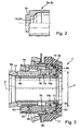
- FIG. 3 shows an input / output device 1 in the starting position, d. H. without pressurization of the pistons 3a, 3b.
- the two extensions 7a and 7b can be seen, which end in the punches 16a and 16b, which abut in this position on the pressure surfaces 19, 20 of the pistons 3a and 3b.
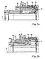
- FIG. 4a shows one of the three pistons 3a arranged concentrically around the pitch circle 2 in the disengaged state and FIG. 4b correspondingly in the engaged state.
- Figures 5a and 5b illustrate the operation of the input / Ausgur Anlagen 1 for the piston 3b accordingly.
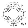
- FIG. 6 shows the arrangement of the pressure surfaces of the two rings 4a and 4b in the installed state. From this it can be seen that the pressure force regardless of the choice of the pressure piston 3 a or 3 b axially always on the imaginary pitch circle diameter 2 of the extensions 7 a and 7 b, which is aligned with the pitch circle diameter of the piston 3 a and 3 b, is transmitted. As a result, a largely loss-free transmission of the pressure force from the pistons 3a and 3b to the rings 4a and 4b is ensured.
Landscapes
- Engineering & Computer Science (AREA)
- General Engineering & Computer Science (AREA)
- Mechanical Engineering (AREA)
- Health & Medical Sciences (AREA)
- Public Health (AREA)
- Hydraulic Clutches, Magnetic Clutches, Fluid Clutches, And Fluid Joints (AREA)
Abstract
Description
Die Erfindung betrifft eine Stelleinrichtung zur Übertragung einer Stellkraft einer Ein-/Ausrückeinrichtung auf eine Doppelkupplung zum Kuppeln einer Antriebswelle mit zwei Getriebeeingangswellen.The invention relates to an adjusting device for transmitting a control force of an input / Ausrückeinrichtung on a dual clutch for coupling a drive shaft with two transmission input shafts.
Stelleinrichtungen zum wechselseitigen Kuppeln der jeweiligen Kupplung einer Antriebswelle mit einer Getriebeeingangswelle sind bereits aus der DE 34 46 460 C2 bekannt, bei der jeweils eine Kupplung mit einer Tellerfeder von je einem mit der betreffenden Tellerfeder verbundenem Stellmechanismus mit einem zur Kupplungsachse koaxial liegenden Ringkolben ausgerückt wird. Die beiden Ringkolben sind dabei im Gehäuse radial voneinander beabstandet.Actuating devices for mutual coupling of the respective clutch of a drive shaft with a transmission input shaft are already known from DE 34 46 460 C2, in each of which a clutch is disengaged with a disc spring of one associated with the disk spring concerned adjusting mechanism with a coaxial to the clutch axis annular piston. The two annular pistons are spaced apart radially in the housing.
Eine weitere Möglichkeit, eine Antriebswelle mit einer Getriebeeingangswelle über wechselseitiges Kuppeln der jeweiligen Kupplung einer Doppelkupplung in Eingriff zu bringen und dabei die Hystereseeigenschaften der vorgenannten Lösung zu verbessern, wird in der DE 199 53 091 C1 beschrieben. Hierbei wird die hydraulische Fläche der zwei koaxial zur Kupplungsachse liegenden Ringkolben, wie sie die DE 34 46 460 C2 offenbart, ersetzt durch mehrere Teilflächen, die sich aus den Druckflächen stangenförmig ausgebildeter Einzelkolben ergeben. Diese Einzelkolben, hier als Stellmotore bezeichnet, werden bei Betätigung mit Druckmittel beaufschlagt. Jeder Kupplung sind dabei drei mit ihrer Achse parallel zur Kupplungsachse angeordnete Stellmotoren zugeordnet. Alle 6 Stellmotoren liegen auf einem zur Kupplungsachse koaxial verlaufendem Teilkreis, wobei die jeweils 3 einer Kupplung zugeordneten Stellkolben um jeweils 120° zueinander angeordnet sind und im Betriebszustand immer synchron mit Druck beaufschlagt werden.A further possibility for bringing a drive shaft into engagement with a transmission input shaft via mutual coupling of the respective clutch of a double clutch and thereby improving the hysteresis properties of the abovementioned solution is described in DE 199 53 091 C1. Here, the hydraulic surface of the two coaxial with the clutch axis annular piston, as disclosed in DE 34 46 460 C2, replaced by a plurality of partial surfaces resulting from the pressure surfaces rod-shaped single piston. These individual pistons, referred to here as servo motors, are acted upon by pressure medium. Each clutch are assigned three with its axis parallel to the clutch axis arranged servomotors. All 6 servomotors are located on a coaxially extending to the coupling axis pitch circle, wherein the respective 3 of a clutch associated adjusting pistons are arranged at 120 ° to each other and are always acted upon synchronously in the operating state with pressure.
Diese Lösungen haben jedoch den Nachteil, dass die Druckbeaufschlagung eines Kolbens bzw. eines Kolbensystems (bestehend aus drei Kolben) nie zentrisch für jeden einzelnen Kolben erfolgt, so dass jeder immer nur exzentrisch mit Druck beaufschlagt wird. Das führt zum Verkippen der Kolben gegenüber ihrer Lauffläche im Zylinder, damit zu erhöhter Reibung und letztendlich zu Verschleiß der Kolben und deren Laufflächen.However, these solutions have the disadvantage that the pressurization of a piston or a piston system (consisting of three pistons) is never done centrally for each piston, so that each is only ever eccentrically pressurized. This leads to tilting of the piston against its tread in the cylinder, thus increased friction and ultimately to wear of the pistons and their treads.
Außerdem sind die Kolben in ihrer Länge der entsprechenden Lauffläche und damit der Länge der Zylinder angepasst, was das Gewicht der Ein-/Ausrückeinrichtung negativ beeinflusst.In addition, the pistons are adapted in their length of the corresponding tread and thus the length of the cylinder, which adversely affects the weight of the input / Ausrückeinrichtung.
Weiterhin sind bei der DE 199 53 091 C1 die drei Kolben mechanisch nicht miteinander gekoppelt, so dass bei unterschiedlich hohen Druckkräften jeder Kolben unterschiedlich weit ausfährt. Dies führt zu einer Verkippung des Lagers und damit zu dessen Kollision mit dem Gehäuse. Von Nachteil ist weiterhin die direkte Anbindung der drei Kolben an das jeweilige Lager. Das führt zu einer punktförmigen Belastung des Lagers und damit zur Herabsetzung der Lebensdauer des Lagers.Furthermore, in DE 199 53 091 C1, the three pistons are not mechanically coupled to each other, so that at different high pressure forces each piston extends to different heights. This leads to a tilting of the bearing and thus to its collision with the housing. Another disadvantage is the direct connection of the three pistons to the respective bearing. This leads to a punctiform load on the bearing and thus to reduce the life of the bearing.
Daher ist es Aufgabe der Erfindung, unter Beibehaltung einer vorgegebenen Bauraumgröße eine Ein-/Ausrückeinrichtung vorzuschlagen, mit der eine zentrische und axial geführte Übertragung hoher Druckkräfte bei kleiner Dimensionierung der Kolben auf den Lagerring des jeweiligen Ausrücklagers bzw. die zugeordnete Kupplung realisierbar ist.It is therefore an object of the invention, while maintaining a predetermined space size to propose an input / output device, with a centric and axially guided transmission of high pressure forces at small dimensions of the piston on the bearing ring of the respective release bearing and the associated clutch can be realized.
Diese Aufgabe wird mit den Merkmalen des Patentanspruchs 1 in vorteilhafter Weise gelöst, indem die Druckflächen der Kolben der jeweils zugeordneten Kupplung miteinander koppelbar sind und die Führungsbahn der Kolben verlängerbar ist.This object is solved with the features of claim 1 in an advantageous manner by the pressure surfaces of the pistons of each associated clutch can be coupled together and the guideway of the piston is extendable.
Dazu stehen in vorteilhafter Weise mindestens zwei konzentrisch um die Achse der Ein-/Ausrückeinrichtung zwischen dem äußeren zylindrischen Grundkörperteil und dem inneren zylindrischen Grundkörperteil angeordnete Ringe in Wirkverbindung mit jeweils mindestens zwei um diese Achse auf einem Teilkreis angeordneten Kolben. Besonders vorteilhaft ist es immer, drei Kolben für die Betätigung einer Kupplung vorzusehen, die jeweils um 120° zueinander versetzt angeordnet sind, damit bereits bei der Krafteinleitung in den Ring eine möglichst gleichmäßige Anlage an diesem gewährleistet ist. Die jeweils drei für eine Kupplung über den Teilkreisdurchmesser um 120° zueinander versetzt angeordneten Kolben können zu den anderen drei der zweiten Kupplung zugehörigen Kolben beliebig versetzt auf dem Teilkreisdurchmesser angeordnet werden.For this purpose, at least two concentrically arranged around the axis of the input / Ausrückeinrichtung between the outer cylindrical main body part and the inner cylindrical basic body part rings are in operative connection with at least two pistons arranged around this axis on a pitch circle. It is always particularly advantageous to provide three pistons for the actuation of a clutch, which are each offset by 120 ° to each other, so that even when the force is introduced into the ring a uniform possible investment in this is ensured. The three pistons, which are offset by 120.degree. Relative to each other for a coupling over the pitch circle diameter, can be arranged at any desired offset on the pitch circle diameter relative to the other three pistons associated with the second clutch.
Die Koppelung der Druckflächen für ein Ausrücklager erfolgt dadurch, indem die Druckflächen der drei für die jeweilige Kupplung zuständigen Kolben über einen Adapter in Form eines Rings miteinander verbunden werden. Dieser steht über so genannte Fortsätze in unmittelbarer Verbindung mit jedem einzelnen Kolben, die dadurch indirekt miteinander verbunden werden.The coupling of the pressure surfaces for a release bearing is effected by the pressure surfaces of the three responsible for each clutch piston via an adapter in the form of a ring are interconnected. This is about so-called extensions in direct connection with each individual piston, which are thereby indirectly connected.
Diese Lösung ermöglicht, dass der Druck synchron über vorgesehene Anschlüsse in der Bodenplatte des Grundkörpers der Ein-/Ausrückeinrichtung eingeleitet wird, der auf jeden der drei Kolben zentrisch wirkt. Da die Kolben und der jeweilige Lagerring nicht auf einer Wirkungslinie liegen, wird dieser Versatz durch den zugehörigen Ring ausgeglichen.
Die Weitergabe der Druckkraft erfolgt somit nicht direkt über die jeweiligen Kolbenflächen auf einen Lagerring, sondern über die Stirn-(Druck)fläche des entsprechenden Rings. Umgekehrt werden von der Kupplung herrührende Belastungsunterschiede über den Ring ausgeglichen und die einzelnen Kolben werden in ihrer Führungsbahn nicht verkantet. Das führt wiederum dazu, dass Verschleiß sowohl an der Führungsbahn als auch am Kolben vermieden wird.This solution allows the pressure to be introduced in synchronism via provided ports in the bottom plate of the main body of the input / output device, which is applied to each of the three pistons centric acts. Since the pistons and the respective bearing ring are not on a line of action, this offset is compensated by the associated ring.
The transfer of the pressure force is thus not directly on the respective piston surfaces on a bearing ring, but on the front (pressure) surface of the corresponding ring. Conversely, load differentials originating from the clutch are balanced across the ring and the individual pistons are not tilted in their guideway. This in turn means that wear on both the guideway and the piston is avoided.
Auf diese Weise wird die Ausrückkraft gleichmäßig auf den Lagerring des Ausrücklagers übertragen. Diese gleichmäßige Kraftverteilung wird außerdem ermöglicht durch die konzentrische Anordnung der Ringe um die Achse der Ein-/Ausrückeinrichtung und deren senkrecht zu dieser verlaufenden Ebenen der Druckflächen.In this way, the release force is transmitted evenly to the bearing ring of the release bearing. This uniform force distribution is also made possible by the concentric arrangement of the rings about the axis of the input / Ausrückeinrichtung and their perpendicular to this extending planes of the pressure surfaces.
Ein weiterer Vorteil der erfinderischen Lösung besteht darin, dass der innere Ring auf dem inneren zylindrischen Grundkörperteil gegenüber dem äußeren Ring und der äußere Ring am äußeren Durchmesser des zylindrischen Grundkörperteils geführt wird und axial verschiebbar ist.
Eine weitere Möglichkeit wäre auch, dass der äußere Ring auf dem inneren Ring gegenüber dem äußeren zylindrischen Grundkörperteils axial verschiebbar ist.
Dadurch wird erreicht, dass beispielsweise das äußere Ausrücklager gegenüber dem inneren Ausrücklager unabhängig von diesem axial mittels des entsprechenden Rings verschiebbar istAnother advantage of the inventive solution is that the inner ring is guided on the inner cylindrical body portion relative to the outer ring and the outer ring on the outer diameter of the cylindrical body portion and is axially displaceable.
Another possibility would be that the outer ring on the inner ring relative to the outer cylindrical body portion is axially displaceable.
This ensures that, for example, the outer release bearing relative to the inner release bearing is independent of this axially displaceable by means of the corresponding ring
Die Kraftübertragung erfolgt vorteilhafterweise über mindestens jeweils zwei an den Stirnseiten der kolbenseitigen Enden der Ringe in axialer Richtung angebrachte Fortsätze. Durch die Anpassung der Durchmesser der beiden Ringe wird erreicht, dass der Versatz von Kolben zu Ring gleich groß ist. Die 6 Fortsätze werden somit alle gleichmäßig belastet.
Da, wie bereits erwähnt, jeweils von drei Kolben die Kraft auf eine Kupplung übertragen wird, müssen die Ringe jeweils ebenfalls mit drei Fortsätzen versehen sein. Diese sind wiederum um 120° zueinander versetzt angeordnet und haben alle die gleiche Länge. Das hat den Vorteil, dass im drucklosen Zustand der Ein-/Ausrückeinrichtung, sowohl die Kolben an der Bodenplatte des Grundkörpers als auch alle 6 Fortsätze an den 6 Kolbenflächen anliegen. Dabei nehmen die beiden Ringe eine Ausgangsposition ein, in der die kolbenseitigen Stirnflächen in einer Ebene liegen. Diese Ausgangsstellung kann beispielsweise als Referenzpunkt für eine Justierung der Ringe bzw. der Lagerringe für jedes Ausrücklager zur Tellerfeder der jeweiligen Kupplung genutzt werden.The power transmission is advantageously carried out via at least two extensions attached to the end faces of the piston-side ends of the rings in the axial direction. By adjusting the diameter of the two rings is achieved that the offset from piston to ring is the same size. The 6 extensions are thus all evenly loaded.
Since, as already mentioned, each of three pistons, the force is transmitted to a clutch, the rings must each also be provided with three extensions. These are in turn offset by 120 ° to each other and all have the same length. This has the advantage that abut both the piston on the bottom plate of the body and all 6 projections on the 6 piston surfaces in the pressureless state of the input / Ausrückeinrichtung. The two rings assume a starting position, in which the piston-side end faces lie in one plane. This starting position can be used for example as a reference point for an adjustment of the rings or the bearing rings for each release bearing for disc spring of the respective clutch.
Sowohl für die axiale Führung beider Ringe innerhalb des Grundköpers bzw. der Ringe zueinander als auch für die Auslegung der jeweils erforderlichen Führungsfläche ist es weiterhin besonders vorteilhaft, dass an den kolbenseitigen Stirnseiten beider Ringe wiederum drei am Umfang angeordnete Ausnehmungen gleicher Größe vorgesehen sind, die sich in axialer Richtung über die Breite des jeweiligen Rings erstrecken, wobei immer im Wechsel nach einer Ausnehmung ein Fortsatz folgt.Both for the axial guidance of both rings within the basic body or the rings to each other and for the interpretation of the respective required guide surface, it is also particularly advantageous that three recesses of the same size arranged on the circumference are provided on the piston-side end faces of both rings, which themselves extend in the axial direction over the width of the respective ring, wherein always followed alternately after a recess an extension.
Bei der Paarung der Ringe korrespondiert immer beispielsweise eine Ausnehmung des inneren Rings mit einem Fortsatz des äußeren Rings. Diesem Prinzip folgend stehen die Fortsätze des inneren Rings mit den Ausnehmungen des äußeren Rings in Verbindung. Durch diese konstruktive Ausbildung können die Fortsätze massiv ausgebildet werden, was für die Übertragung hoher Kräfte sehr vorteilhaft ist und die Werkstoffbelastung verringert.When pairing the rings always corresponds, for example, a recess of the inner ring with an extension of the outer ring. Following this principle, the extensions of the inner ring are in communication with the recesses of the outer ring. Through this structural design, the extensions can be made massive, which is very advantageous for the transmission of high forces and reduces the material load.
Ein weiterer Vorteil der erfindungsgemäßen Lösung besteht darin, dass die Fortsätze der Ringe in zylindrischen Stempeln enden, die eine möglichst verlustfreie Kraftübertragung garantieren. Außerdem fluchten die Symmetrieachsen der Paarungselemente mit denen der Kolben, was ebenfalls für eine optimale Kraftübertragung vom Kolben auf den entsprechenden Ring Voraussetzung ist und damit eine Verkippung der Kolben in ihren Führungsbahnen ausschließt. Dadurch wird ebenfalls eine zusätzliche Reibung vermieden und somit die Lebensdauer der Ein-/Ausrückeinrichtung verlängert.Another advantage of the solution according to the invention is that the extensions of the rings end in cylindrical punches, which guarantee a lossless power transmission as possible. In addition, the axes of symmetry of the mating elements are aligned with those of the pistons, which is also a prerequisite for optimum power transmission from the piston to the corresponding ring and thus precludes tilting of the pistons in their guideways. As a result, an additional friction is also avoided and thus extends the life of the input / Ausrückeinrichtung.
Die Grundlage für die möglichst verlustfreie Kraftübertragung wird gemäß der Erfindung dadurch geschaffen, dass die Kolben hohl ausgeführt sind und damit die Druckflächen ins Innere des einzelnen Kolbens verlegt werden. Im Innern der Kolben bildet die Druckfläche am Ende einer zylindrischen Ausnehmung den Abschluss des Hohlraums. Mit der zylindrischen Ausnehmung wird gleichzeitig eine axiale Führung für die an der Druckfläche anliegenden Stempel der Fortsätze des jeweiligen Rings erreicht.The basis for the lossless power transmission is provided according to the invention characterized in that the pistons are hollow and thus the pressure surfaces are moved into the interior of the individual pistons. Inside the piston, the pressure surface at the end of a cylindrical recess forms the end of the cavity. With the cylindrical recess an axial guide for the voltage applied to the pressure surface punch of the extensions of the respective ring is achieved simultaneously.
Vorteilhaft ist es außerdem, unter Berücksichtigung der Größe der auftretenden Kräfte alle miteinander in Verbindung stehenden Teile, wie den Grundkörper, die Ringe Kolben aus einem gießbaren Material herzustellen. Auf diese Weise können spanende Bearbeitungsschritte entfallen, was zu einer Zeit- und Materialeinsparung führt und letztendlich die Herstellungskosten erheblich senkt.It is also advantageous, taking into account the size of the forces occurring all interconnected parts, such as the main body to make the piston rings of a castable material. In this way, machining steps can be omitted, which leads to a time and material savings and ultimately significantly reduces manufacturing costs.
Die Erfindung soll nachfolgend an einem Ausführungsbeispiel näher erläutert werden.The invention will be explained in more detail below using an exemplary embodiment.
Es zeigen:
- Fig. 1
- eine räumliche Ansicht einer erfindungsgemäßen Ein-/Ausrückeinrichtung in Explosionsdarstellung,
- Fig. 2
- einen Kolben,
- Fig. 3
- einen Schnitt durch eine erfindungsgemäße Ein-/Ausrückeinrichtung,
- Fig. 4a
- einen Teilschnitt durch die Ein-/Ausrückeinrichtung gemäß Fig. 3, wobei die
Kolben 3a mit Druck beaufschlagt sind und der Ring 4a ausgerückt ist, - Fig. 4b
- einen Teilschnitt gemäß Fig. 3, wobei sich der
Ring 4a und somit auch dieKolben 3a sich in ihrer Ausgangstellung befinden, - Fig. 5a
- einen Teilschnitt durch den Nehmerzylinder gemäß Fig. 3, wobei die
Kolben 3b mit Druck beaufschlagt sind und derRing 4b ausgerückt ist, - Fig. 5b
- einen Teilschnitt gemäß Fig. 3, wobei sich der
Ring 4b und somit auch dieKolben 3b sich in ihrer Ausgangstellung befinden, - Fig. 6
Druckflächen der Ringe 4a und 4b (Ringe im eingebauten Zustand)
- Fig. 1
- a spatial view of an input / output device according to the invention in an exploded view,
- Fig. 2
- a piston,
- Fig. 3
- a section through an inventive in / Ausrückeinrichtung,
- Fig. 4a
- a partial section through the input / output device of FIG. 3, wherein the
piston 3a are pressurized and thering 4a is disengaged, - Fig. 4b
- a partial section of FIG. 3, wherein the
ring 4a and thus also thepiston 3a are in their initial position, - Fig. 5a
- a partial section through the slave cylinder of FIG. 3, wherein the
piston 3b are pressurized and thering 4 b is disengaged, - Fig. 5b
- a partial section of FIG. 3, wherein the
ring 4b and thus also thepiston 3b are in their initial position, - Fig. 6
- Pressure surfaces of the
rings
Die Ein-/Ausrückvorrichtung bzw. der Nehmerzylinder besteht gemäß Figur 1 im Wesentlichen aus einem doppelzylindrischen Grundkörper 9 mit einem inneren zylindrischen Grundkörperteil 9a und einem äußeren zylindrischen Grundkörperteil 9b, der nach einer Seite hin offen ist, wobei das innere zylindrische Grundkörperteil 9a längenmäßig über das äußere zylindrische Grundkörperteil 9b hinausragt. Die andere Seite des Grundkörpers 9 ist durch eine Bodenplatte 9c verschlossen. In diese Bodenplatte 9c sind im Zwischenraum zwischen äußerem zylindrischen Grundkörperteil 9b und innerem zylindrischem Grundkörperteil 9a 6 Grundlochbohrungen 10 eingebracht. Diese Grundlochbohrungen 10 weisen wiederum jeweils eine Durchgangsbohrung für einen Fluidanschluss für die Druckmittelzufuhr 15 auf.According to FIG. 1, the engaging / disengaging device or the slave cylinder consists essentially of a double-cylindrical
Die Grundlochbohrungen 10 sind auf einem konzentrischen Teilkreis 2 angeordnet und jeweils in einem Winkel von 60° voneinander beabstandet. Die Stärke der Bodenplatte 9c des Grundkörpers 9 richtet sich im Wesentlichen nach der Länge der Führung und die Größe des Durchmessers der einzelnen Grundlochbohrung 10 nach dem darin aufzunehmenden Kolben 3a, 3b. Vorteilhafter Weise werden gleiche Durchmessergrößen der 6 Grundlochbohrungen 10 gewählt und zur maximalen Raumausnutzung diese vom Abstand zwischen äußerem zylindrischen Grundkörperteil 9b und innerem zylindrischen Grundkörperteil 9a bestimmt. Die Durchmesser der Kolben 3a, 3b sind damit entsprechend ebenfalls gleich groß.The
Jede Grundlochbohrung 10 stellt einen Zylinder für den jeweiligen Kolben 3a, 3b dar und dient zu dessen Aufnahme.Each
In diesem Grundkörper 9 werden die Ringe 4a und 4b zwischen dem inneren zylindrischen Grundkörperteil 9a und dem äußeren zylindrischen Grundkörperteil 9b aufgenommen und geführt. Aus dieser Figur ist ebenfalls ersichtlich, dass am kolbenseitigen Ende der Ringe 4a, 4b, Fortsätze 7a, 7b angebracht sind, deren Füße teilweise die Mantelfläche des jeweiligen Rings 4a, 4b überragen. Gleichzeitig ist erkennbar, dass diese Fortsätze 7a, 7b in zylindrischen Stempeln 16a, 16b enden. Da die Fortsätze 7a, 7b einerseits zur axialen Bewegung innerhalb des Grundkörpers 9 und damit zur Kraftübertragung von den Kolben auf die Lagerringe dienen und dafür für hohe Drücke eine bestimmte Stabilität aufweisen müssen, ist deren Querschnitt entsprechend auszulegen. Andererseits wird durch sie eine Verringerung der Breite der Ringe 4a, 4b bzw. eine Verlängerung der Ausrückfläche möglich. Diesen beiden Funktionen gerecht zu werden und außerdem den Bauraum nicht zu vergrößern, werden die Fortsätze 7a, 7b in deren Form angepassten Ausnehmungen 12a, 12b vom jeweils anderen Ring 4b, 4a aufgenommen. Um dem geringen Raumangebot Rechnung zu tragen, sind die Fortsätze 7a, 7b so gestaltet, dass sie einen entsprechend starken Fuß aufweisen, der hauptsächlich an der kolbenseitigen Stirnseite des Rings 4a, 4b angebracht ist. Dieser Fuß wird von einem zylindrischen Stempel 16a, 16b abgelöst, dessen Symmetrieachse auf dem Durchmesser des Rings 4a, 4b liegt. Zur Erhöhung der Festigkeit der Fortsätze 7a, 7b bei gleichzeitig optimaler Auslegung der Druckfläche wird der jeweils der Kontaktfläche zugewandte Teil des Stempels 16a, 16b über den Fuß des Fortsatzes 7a, 7b hinaus verlängert und reicht auf einer Länge, die der Länge des Fortsatzes 7a, 7b des kontaktierten Rings 4a, 4b entspricht, in den Innenumfang des Rings 4a, 4b hinein.In this
Die Stempel 16a, 16b mit einer Länge und mit einem Durchmesser, die in vorteilhafter Weise der axialen Ausdehnung und dem Durchmesser, die den Abmessungen des zylindrischen Hohlraums eines Kolbens 3a, 3b entsprechen, stehen mit ihren Stirnflächen mit den Druckflächen 19, 20 der Kolben 3a, 3b in Kontakt.The
Die besondere Gestaltung eines Kolbens 3a, 3b geht aus der Figur 2 hervor. Jeder Kolben 3a, 3b ist mit einem Ansatz 3c versehen, mit dem er axial an der Bodenplatte 9c anliegt und der gleichzeitig zur Aufnahme einer Dichtung 11 dient, dass das sich im Zylinder 10 befindende Fluid nicht in den diesen umgebenden Grundkörper 9 gelangen kann.The special design of a
Wird die Ein-/Ausrückvorrichtung 1 durch Fluid mit Druck beaufschlagt, wird dieser über die in der Bodenplatte 9c des Grundkörpers 9 vorgesehenen Bohrungen auf die der entsprechenden Kupplung zugeordneten drei Kolben 3a oder 3b übertragen. Dadurch werden die Kolben 3a oder 3b in ihren Zylindern 10 axial in Richtung Ausrücklager 6a, 6b bewegt.If the input / output device 1 is pressurized by fluid, it is transmitted via the holes provided in the
Wie bereits erwähnt, sind die Ringe 4a, 4b über entsprechend vorgesehene kolbenförmige Fortsätze 7a, 7b, die in zylinderförmige Stempel 16a und 16b übergehen, mit den jeweils zugeordneten Kolben 3a, 3b kontaktierbar und spielbehaftet axial ineinander verschiebbar. Auf diese Weise sind die Kolben 3a bzw. 3b indirekt miteinander verbunden. Weiterhin sind beispielsweise den Fortsätzen 7b am Ring 4b die Ausnehmungen 12a des Ringes 4a zugeordnet. Entsprechend sind die Führungsflächen der Ausnehmungen 12b des Ringes 4b den Fortsätzen des Ringes 4a zugeordnet.As already mentioned, the
Die Ausnehmungen 12a des Ringes 4a weisen gegenüber dem Ring 4b die Besonderheit auf, dass sie nicht über die gesamte Breite des Ringes 4a verlaufen, sondern vor dem Ende, das an dem Lagerring 6a anliegt.The
Bei Druckbeaufschlagung der entsprechenden drei Kolben 3a bzw. 3b drücken diese gleichzeitig auf die jeweiligen Fortsätze 7a oder 7b, wodurch der Ring 4a bzw. der Ring 4b mit dem Ausrücklager 6a oder 6b ein- oder ausgerückt und damit die entsprechende Kupplung betätigt wird.Upon pressurization of the corresponding three
Die Figur 3 zeigt eine Ein-/Ausrückeinrichtung 1 in der Ausgangsstellung, d. h. ohne Druckbeaufschlagung der Kolben 3a, 3b. In dieser Figur sind auch die beiden Fortsätze 7a und 7b erkennbar, die in den Stempeln 16a und 16b enden, die in dieser Stellung an den Druckflächen 19, 20 der Kolben 3a und 3b anliegen.FIG. 3 shows an input / output device 1 in the starting position, d. H. without pressurization of the
Die Figur 4a zeigt einen der drei der konzentrisch um den Teilkreis 2 angeordneten Kolben 3a im ausgerückten und die Figur 4b entsprechend im eingerückten Zustand. Die Figuren 5a und 5b verdeutlichen die Funktionsweise der Ein-/Ausrückeinrichtung 1 für die Kolben 3b entsprechend.FIG. 4a shows one of the three
Die Figur 6 zeigt die Anordnung der Druckflächen der beiden Ringe 4a und 4b im eingebauten Zustand. Hieraus ist erkennbar, dass die Druckkraft unabhängig von der Wahl der mit Druck beaufschlagten Kolben 3a oder 3b axial immer über den gedachten Teilkreisdurchmesser 2 der Fortsätze 7a bzw. 7b, der mit dem Teilkreisdurchmesser der Kolben 3a bzw. 3b fluchtet, übertragen wird. Dadurch wird eine weitestgehend verlustfreie Übertragung der Druckkraft von den Kolben 3a bzw. 3b auf die Ringe 4a bzw. 4b gewährleistet.FIG. 6 shows the arrangement of the pressure surfaces of the two
- 11
- Ein-/Ausrückvorrichtung / NehmerzylinderIn / out device / slave cylinder
- 22
- Konzentrischer TeilkreisConcentric circle
- 3a3a
- Kolbenpiston
- 3b3b
- Kolbenpiston
- 3c3c
- Ansatzapproach
- 4a4a
- innerer Ringinner ring
- 4b4b
- äußerer Ringouter ring
- 55
- Achse der Ein-/AusrückvorrichtungAxis of the input / output device
- 6a6a
- inneres Ausrücklagerinner release bearing
- 6b6b
- äußeres Ausrücklagerouter release bearing
- 7a7a
- Fortsätzeprojections
- 7b7b
- Fortsätzeprojections
- 8a8a
- Dichtungenseals
- 8b8b
- Dichtungenseals
- 99
- Grundkörperbody
- 9a9a
- inneres zylindrisches Grundkörperteilinner cylindrical body part
- 9b9b
- äußeres zylindrisches Grundkörperteilouter cylindrical body part
- 9c9c
- Bodenplattebaseplate
- 1010
- Grundlochbohrung, ZylinderBlind hole, cylinder
- 1111
- Dichtungpoetry
- 12a12a
- Ausnehmungrecess
- 12b12b
- Ausnehmungrecess
- 1515
- DruckmittelzufuhrPressure medium supply
- 16a16a
- Stempelstamp
- 16b16b
- Stempelstamp
- 1717
- Gehäusecasing
- 1818
- Schrägeslope
- 1919
-
Druckfläche Kolben 3a
Pressure surface piston 3a - 2020
-
Druckfläche Kolben 3b
Pressure surface piston 3b - 2121
-
Stirnfläche des Rings 4aEnd face of the
ring 4a - 2222
-
Stirnfläche des Rings 4bFace of the
ring 4b - 2323
- Anschlagattack
Claims (12)
- A regulating mechanism for transmitting a regulating power of an engaging/disengaging apparatus (1) to a dual clutch, having at least two pressurizable pistons (3a, 3b) for each clutch positioned parallel to the clutch axis or to the axis (5) of the engaging/ disengaging apparatus (1), which pistons are located on a graduated circle (2) which is concentric to the axis (5), characterized in that the pressure surfaces (19) of the pistons (3a) can be coupled with each other and the pressure surfaces (20) of the pistons (3b) can be coupled mechanically with each other, and the guide way of the pistons (3a, 3b) can be lengthened.
- The regulating mechanism according to Claim 1, characterized in that at least two rings (4a, 4b) positioned concentrically around the axis (5) between the outer cylindrical body piece (9b) and the inner cylindrical body piece (9a) have a working connection with at least two pistons (3a, 3b) that are positioned around the axis (5) on the graduated circle (2).
- The regulating mechanism according to Claim 2, characterized in that the ring (4a) on the inner cylindrical body piece (9a) is axially movable relative to the ring (4b), and the ring (4b) on the outer cylindrical body piece (9b) is axially movable relative to the inner ring (4a).
- The regulating mechanism according to Claims 1 through 3, characterized in that the face (21) of the ring (4a) is in contact with the clutch release bearing (6a) and the face (22) of ring (4b) is in contact with clutch release bearing (6b), and the planes of the faces (21, 22) run perpendicular to the axis (5) of the engaging/disengaging apparatus (1).
- The regulating mechanism according to Claims 1 through 4, characterized in that a size-based dependency exists between the inner diameter of the ring (4b) or the outer diameter of the ring (4a) and the diameter of the graduated circle (2).
- The regulating mechanism according to Claims 1 through 5, characterized in that the end faces of the rings (4a, 4b) on the piston side each have at least two projections (7a, 7b) in the axial direction, their end parts being formed of cylindrical plungers (16a, 16b) and the projections (7a, 7b) being of equal length.
- The regulating mechanism according to Claims 1 through 6, characterized in that on the faces of the rings (4a, 4b) on the piston side there are at least two recesses (12a, 12b) positioned on the circumference, which extend over the width of the rings (4a, 4b) in the axial direction, each recess (12a, 12b) being followed by a projection (7a, 7b).
- The regulating mechanism according to Claim 7, characterized in that the projections (7b) of the ring (4b) correspond in position to the recesses (12a) of ring (4a) and are axially movable in them.
- The regulating mechanism according to Claims 6 through 8, characterized in that the axes of symmetry of the plungers (16a, 16b) of the projections (7a, 7b) are aligned with those of the recesses (12a, 12b) and those of the pistons (3a, 3b).
- The regulating mechanism according to Claims 1, 6 and 9, characterized in that the pistons (3a, 3b) are hollow, and the plungers (16a, 16b) are in contact with the inner piston surfaces (19, 20).
- The regulating mechanism according to one of Claims 2 through 10, characterized in that the total width of the rings (4a) and (4b) corresponds to the diameter of a piston (3a, 3b).
- The regulating mechanism according to Claims 2 through 11, characterized in that the body (9), the rings (4a, 4b) and the pistons (3a, 3b) can be produced from a castable material.
Applications Claiming Priority (2)
| Application Number | Priority Date | Filing Date | Title |
|---|---|---|---|
| DE102004002344 | 2004-01-16 | ||
| DE102004002344 | 2004-01-16 |
Publications (2)
| Publication Number | Publication Date |
|---|---|
| EP1555452A1 EP1555452A1 (en) | 2005-07-20 |
| EP1555452B1 true EP1555452B1 (en) | 2007-01-31 |
Family
ID=34609585
Family Applications (1)
| Application Number | Title | Priority Date | Filing Date |
|---|---|---|---|
| EP04030388A Expired - Lifetime EP1555452B1 (en) | 2004-01-16 | 2004-12-22 | Actuating device to transmit piston forces to the engag-/disengaging device of a twin clutch. |
Country Status (7)
| Country | Link |
|---|---|
| US (1) | US7267215B2 (en) |
| EP (1) | EP1555452B1 (en) |
| JP (1) | JP2005201452A (en) |
| KR (1) | KR20050075699A (en) |
| CN (1) | CN100421982C (en) |
| AT (1) | ATE353122T1 (en) |
| DE (2) | DE502004002827D1 (en) |
Families Citing this family (25)
| Publication number | Priority date | Publication date | Assignee | Title |
|---|---|---|---|---|
| EP1582759B1 (en) * | 2004-03-31 | 2007-03-14 | LuK Lamellen und Kupplungsbau Beteiligungs KG | Hydraulic actuating system for clutches. |
| EP2201258B2 (en) * | 2007-10-11 | 2015-02-25 | Schaeffler Technologies GmbH & Co. KG | Clutch actuation system |
| DE102009034401B4 (en) | 2008-08-11 | 2019-07-04 | Schaeffler Technologies AG & Co. KG | clutch release |
| DE102009050346B4 (en) | 2008-11-17 | 2019-08-08 | Schaeffler Technologies AG & Co. KG | Clutch release system with anti-rotation lock for slave cylinder pistons |
| DE102009053488B4 (en) | 2008-12-11 | 2019-05-23 | Schaeffler Technologies AG & Co. KG | Device for transmitting a piston force of an input / release device to the respective part clutch of a double clutch |
| DE102009053486B4 (en) | 2008-12-22 | 2019-06-06 | Schaeffler Technologies AG & Co. KG | Clutch release system for a friction clutch |
| DE102009056899B4 (en) | 2008-12-22 | 2019-06-06 | Schaeffler Technologies AG & Co. KG | clutch release |
| DE102009056378B4 (en) | 2008-12-22 | 2019-05-23 | Schaeffler Technologies AG & Co. KG | Clutch actuation system |
| JP2010156402A (en) * | 2008-12-26 | 2010-07-15 | Nsk Ltd | Clutch release bearing device |
| DE112010002678A5 (en) * | 2009-06-22 | 2012-10-31 | Schaeffler Technologies AG & Co. KG | Input / output device for transmitting a piston force to at least one clutch |
| KR101028231B1 (en) * | 2009-06-30 | 2011-04-11 | 현대자동차주식회사 | DCT Control Unit |
| US8636125B2 (en) * | 2009-08-26 | 2014-01-28 | GM Global Technology Operations LLC | Actuation device having wiper seals for a dual clutch transmission |
| GB2474517A (en) * | 2009-10-19 | 2011-04-20 | Gm Global Tech Operations Inc | A clutch actuation device for a dual clutch including concentric slave cylinders |
| JP5500018B2 (en) * | 2010-09-21 | 2014-05-21 | 日産自動車株式会社 | Vehicle clutch control device |
| US8474586B2 (en) * | 2010-10-18 | 2013-07-02 | GM Global Technology Operations LLC | Clutch actuation assembly with satellite pistons |
| DE112011104293A5 (en) * | 2010-12-09 | 2013-09-12 | Schaeffler Technologies AG & Co. KG | Releaser for a double clutch with travel sensing |
| DE102012221535A1 (en) * | 2011-12-23 | 2013-06-27 | Schaeffler Technologies AG & Co. KG | Friction clutch for drive train of motor vehicle, particularly for transferring torque from crankshaft of engine to input shaft of transmission of motor vehicle, has central plate for rotationally fixed connection with flywheel |
| JP5841454B2 (en) * | 2012-02-24 | 2016-01-13 | 株式会社エクセディ | Twin clutch cylinder device and twin clutch operating device having the same |
| EP2917601B1 (en) * | 2012-11-07 | 2018-12-12 | Schaeffler Technologies AG & Co. KG | Double clutch with clutch-actuating device |
| US9249883B2 (en) * | 2013-01-17 | 2016-02-02 | Gm Global Technology Operations, Llc | Anti-rotate attenuation device |
| DE112014004374A5 (en) * | 2013-09-24 | 2016-06-23 | Schaeffler Technologies AG & Co. KG | Hydrostatic clutch actuator |
| DE102014226299B3 (en) * | 2014-12-17 | 2015-10-15 | Schaeffler Technologies AG & Co. KG | Slave cylinder with transport lock and method for fixing a piston to a release bearing |
| CN106286632A (en) * | 2016-09-28 | 2017-01-04 | 江阴职业技术学院 | Automobile gearbox double clutch |
| DE102019117109A1 (en) * | 2019-06-25 | 2020-12-31 | Fte Automotive Gmbh | Actuating module for actuating torque transmission devices of a vehicle transmission |
| CN111963582B (en) * | 2020-09-10 | 2022-03-11 | 浙江亚太机电股份有限公司 | Plunger type clutch master cylinder structure with cylinder sleeve |
Family Cites Families (12)
| Publication number | Priority date | Publication date | Assignee | Title |
|---|---|---|---|---|
| US2376545A (en) * | 1937-12-24 | 1945-05-22 | William T Livermore | Transmission |
| US2636585A (en) * | 1946-08-30 | 1953-04-28 | William T Livermore | Automatic fluid pressure transmission |
| FR2216856A5 (en) * | 1973-02-02 | 1974-08-30 | Ferodo Sa | |
| GB2071794B (en) * | 1980-03-17 | 1984-05-02 | Automotive Prod Co Ltd | Rotary transmission control system |
| DE3446460A1 (en) | 1984-12-20 | 1986-07-03 | Dr.Ing.H.C. F. Porsche Ag, 7000 Stuttgart | DOUBLE CLUTCH FOR A MOTOR VEHICLE TRANSMISSION |
| DE3504086A1 (en) * | 1985-02-07 | 1986-08-07 | Fichtel & Sachs Ag, 8720 Schweinfurt | DOUBLE-DRIVER CYLINDER WITH TWO RELEASE BEARINGS FOR THE OPERATION OF TRACTOR DOUBLE CLUTCHES |
| US4875561A (en) * | 1987-10-09 | 1989-10-24 | Borg-Warner Automotive, Inc. | Dual clutch application area and control |
| ES2150832B1 (en) * | 1996-06-12 | 2001-06-16 | Fichtel & Sachs Ag | OPERATING DEVICE FOR THE OPERATION, IN PARTICULAR PNEUMATIC OPERATION, OF A FRICTION CLUTCH. |
| DE19953091C1 (en) * | 1999-11-04 | 2001-08-23 | Daimler Chrysler Ag | Arrangement for coupling a drive shaft with one or both of two gear shafts of a gear change transmission |
| GB2382852B (en) * | 2000-04-28 | 2004-12-01 | Luk Lamellen & Kupplungsbau | Actuating device for a double clutch transmission |
| JP5023372B2 (en) * | 2000-11-22 | 2012-09-12 | シェフラー テクノロジーズ アクチエンゲゼルシャフト ウント コンパニー コマンディートゲゼルシャフト | Clutch device |
| ITTO20020480A1 (en) * | 2002-06-07 | 2003-12-09 | Magneti Marelli Powertrain Spa | BI-CLUTCH TRANSMISSION GROUP FOR A VEHICLE. |
-
2004
- 2004-12-22 EP EP04030388A patent/EP1555452B1/en not_active Expired - Lifetime
- 2004-12-22 DE DE502004002827T patent/DE502004002827D1/en not_active Expired - Lifetime
- 2004-12-22 AT AT04030388T patent/ATE353122T1/en not_active IP Right Cessation
- 2004-12-22 DE DE102004061789A patent/DE102004061789A1/en not_active Withdrawn
-
2005
- 2005-01-12 KR KR1020050002733A patent/KR20050075699A/en not_active Ceased
- 2005-01-13 US US11/034,704 patent/US7267215B2/en not_active Expired - Fee Related
- 2005-01-17 JP JP2005009566A patent/JP2005201452A/en not_active Withdrawn
- 2005-01-17 CN CNB2005100047263A patent/CN100421982C/en not_active Expired - Fee Related
Also Published As
| Publication number | Publication date |
|---|---|
| ATE353122T1 (en) | 2007-02-15 |
| JP2005201452A (en) | 2005-07-28 |
| US20050155835A1 (en) | 2005-07-21 |
| DE102004061789A1 (en) | 2005-08-04 |
| KR20050075699A (en) | 2005-07-21 |
| EP1555452A1 (en) | 2005-07-20 |
| CN1640712A (en) | 2005-07-20 |
| US7267215B2 (en) | 2007-09-11 |
| CN100421982C (en) | 2008-10-01 |
| DE502004002827D1 (en) | 2007-03-22 |
Similar Documents
| Publication | Publication Date | Title |
|---|---|---|
| EP1555452B1 (en) | Actuating device to transmit piston forces to the engag-/disengaging device of a twin clutch. | |
| EP2780614B1 (en) | Actuating device for a rotatable closure part of a valve | |
| DE102011120393B4 (en) | Centrifugally balanced hydraulic clutch assembly | |
| EP1987265B1 (en) | Clamping and/or braking device | |
| DE102009054794B4 (en) | Radial rotary feedthrough and socket for this | |
| DE102015202916B4 (en) | Clutch device with lever operation | |
| DE102011120576A1 (en) | Hydraulic single piston actuator with three positions | |
| EP2916025B1 (en) | Actuating unit for a clutch | |
| EP1548333A1 (en) | Fluid actuated shift device of a transmission | |
| DE102012200217B4 (en) | Neutral adjustment device of an adjustable hydraulic machine | |
| DE69210564T2 (en) | Device for adjusting the ram stroke on a press | |
| DE102013218507A1 (en) | Device for notching | |
| EP2885108B1 (en) | Lifting apparatus having a toggle lever mechanism | |
| DE602004001988T2 (en) | ROTARY VALVE ACTUATOR | |
| DE2403173B2 (en) | Double mechanical seal | |
| EP2047156B1 (en) | Valve device with manual auxiliary actuating mechanism | |
| DE19628117C2 (en) | Rotary drive, in particular swivel motor | |
| EP0676278B1 (en) | Stroke adjusting device for presses or punching machines | |
| EP2777848B1 (en) | Clamping or gripping device | |
| DE1917368B2 (en) | Auxiliary power switching device working with compressed air for synchronized gearboxes in motor vehicles | |
| EP1786593B1 (en) | Braking and clamping device comprising a drive | |
| EP2474754B1 (en) | Self-reinforcing disc brake with pneumatic or electromechanical actuation | |
| EP2396572B1 (en) | Arrangement for creating a shifting force or selection force in a manual transmission | |
| EP2202413A1 (en) | Pneumatic drive with pressure equalisation | |
| AT518408B1 (en) | VALVE CONTROL DEVICE FOR AT LEAST ONE GAS CHANGING VALVE |
Legal Events
| Date | Code | Title | Description |
|---|---|---|---|
| PUAI | Public reference made under article 153(3) epc to a published international application that has entered the european phase |
Free format text: ORIGINAL CODE: 0009012 |
|
| AK | Designated contracting states |
Kind code of ref document: A1 Designated state(s): AT BE BG CH CY CZ DE DK EE ES FI FR GB GR HU IE IS IT LI LT LU MC NL PL PT RO SE SI SK TR |
|
| AX | Request for extension of the european patent |
Extension state: AL BA HR LV MK YU |
|
| 17P | Request for examination filed |
Effective date: 20060120 |
|
| AKX | Designation fees paid |
Designated state(s): AT BE BG CH CY CZ DE DK EE ES FI FR GB GR HU IE IS IT LI LT LU MC NL PL PT RO SE SI SK TR |
|
| GRAP | Despatch of communication of intention to grant a patent |
Free format text: ORIGINAL CODE: EPIDOSNIGR1 |
|
| GRAS | Grant fee paid |
Free format text: ORIGINAL CODE: EPIDOSNIGR3 |
|
| GRAA | (expected) grant |
Free format text: ORIGINAL CODE: 0009210 |
|
| AK | Designated contracting states |
Kind code of ref document: B1 Designated state(s): AT BE BG CH CY CZ DE DK EE ES FI FR GB GR HU IE IS IT LI LT LU MC NL PL PT RO SE SI SK TR |
|
| PG25 | Lapsed in a contracting state [announced via postgrant information from national office to epo] |
Ref country code: NL Free format text: LAPSE BECAUSE OF FAILURE TO SUBMIT A TRANSLATION OF THE DESCRIPTION OR TO PAY THE FEE WITHIN THE PRESCRIBED TIME-LIMIT Effective date: 20070131 Ref country code: SI Free format text: LAPSE BECAUSE OF FAILURE TO SUBMIT A TRANSLATION OF THE DESCRIPTION OR TO PAY THE FEE WITHIN THE PRESCRIBED TIME-LIMIT Effective date: 20070131 Ref country code: PL Free format text: LAPSE BECAUSE OF FAILURE TO SUBMIT A TRANSLATION OF THE DESCRIPTION OR TO PAY THE FEE WITHIN THE PRESCRIBED TIME-LIMIT Effective date: 20070131 Ref country code: IE Free format text: LAPSE BECAUSE OF FAILURE TO SUBMIT A TRANSLATION OF THE DESCRIPTION OR TO PAY THE FEE WITHIN THE PRESCRIBED TIME-LIMIT Effective date: 20070131 Ref country code: FI Free format text: LAPSE BECAUSE OF FAILURE TO SUBMIT A TRANSLATION OF THE DESCRIPTION OR TO PAY THE FEE WITHIN THE PRESCRIBED TIME-LIMIT Effective date: 20070131 Ref country code: DK Free format text: LAPSE BECAUSE OF FAILURE TO SUBMIT A TRANSLATION OF THE DESCRIPTION OR TO PAY THE FEE WITHIN THE PRESCRIBED TIME-LIMIT Effective date: 20070131 |
|
| REG | Reference to a national code |
Ref country code: GB Ref legal event code: FG4D Free format text: NOT ENGLISH |
|
| REG | Reference to a national code |
Ref country code: CH Ref legal event code: EP |
|
| REG | Reference to a national code |
Ref country code: IE Ref legal event code: FG4D Free format text: LANGUAGE OF EP DOCUMENT: GERMAN |
|
| REF | Corresponds to: |
Ref document number: 502004002827 Country of ref document: DE Date of ref document: 20070322 Kind code of ref document: P |
|
| PG25 | Lapsed in a contracting state [announced via postgrant information from national office to epo] |
Ref country code: SE Free format text: LAPSE BECAUSE OF FAILURE TO SUBMIT A TRANSLATION OF THE DESCRIPTION OR TO PAY THE FEE WITHIN THE PRESCRIBED TIME-LIMIT Effective date: 20070430 Ref country code: BG Free format text: LAPSE BECAUSE OF FAILURE TO SUBMIT A TRANSLATION OF THE DESCRIPTION OR TO PAY THE FEE WITHIN THE PRESCRIBED TIME-LIMIT Effective date: 20070430 |
|
| PG25 | Lapsed in a contracting state [announced via postgrant information from national office to epo] |
Ref country code: ES Free format text: LAPSE BECAUSE OF FAILURE TO SUBMIT A TRANSLATION OF THE DESCRIPTION OR TO PAY THE FEE WITHIN THE PRESCRIBED TIME-LIMIT Effective date: 20070512 |
|
| PG25 | Lapsed in a contracting state [announced via postgrant information from national office to epo] |
Ref country code: IS Free format text: LAPSE BECAUSE OF FAILURE TO SUBMIT A TRANSLATION OF THE DESCRIPTION OR TO PAY THE FEE WITHIN THE PRESCRIBED TIME-LIMIT Effective date: 20070531 |
|
| PG25 | Lapsed in a contracting state [announced via postgrant information from national office to epo] |
Ref country code: PT Free format text: LAPSE BECAUSE OF FAILURE TO SUBMIT A TRANSLATION OF THE DESCRIPTION OR TO PAY THE FEE WITHIN THE PRESCRIBED TIME-LIMIT Effective date: 20070702 |
|
| ET | Fr: translation filed | ||
| NLV1 | Nl: lapsed or annulled due to failure to fulfill the requirements of art. 29p and 29m of the patents act | ||
| GBV | Gb: ep patent (uk) treated as always having been void in accordance with gb section 77(7)/1977 [no translation filed] |
Effective date: 20070131 |
|
| REG | Reference to a national code |
Ref country code: IE Ref legal event code: FD4D |
|
| PG25 | Lapsed in a contracting state [announced via postgrant information from national office to epo] |
Ref country code: SK Free format text: LAPSE BECAUSE OF FAILURE TO SUBMIT A TRANSLATION OF THE DESCRIPTION OR TO PAY THE FEE WITHIN THE PRESCRIBED TIME-LIMIT Effective date: 20070131 Ref country code: GB Free format text: LAPSE BECAUSE OF FAILURE TO SUBMIT A TRANSLATION OF THE DESCRIPTION OR TO PAY THE FEE WITHIN THE PRESCRIBED TIME-LIMIT Effective date: 20070131 |
|
| PLBE | No opposition filed within time limit |
Free format text: ORIGINAL CODE: 0009261 |
|
| STAA | Information on the status of an ep patent application or granted ep patent |
Free format text: STATUS: NO OPPOSITION FILED WITHIN TIME LIMIT |
|
| PG25 | Lapsed in a contracting state [announced via postgrant information from national office to epo] |
Ref country code: CZ Free format text: LAPSE BECAUSE OF FAILURE TO SUBMIT A TRANSLATION OF THE DESCRIPTION OR TO PAY THE FEE WITHIN THE PRESCRIBED TIME-LIMIT Effective date: 20070131 Ref country code: RO Free format text: LAPSE BECAUSE OF FAILURE TO SUBMIT A TRANSLATION OF THE DESCRIPTION OR TO PAY THE FEE WITHIN THE PRESCRIBED TIME-LIMIT Effective date: 20070131 |
|
| 26N | No opposition filed |
Effective date: 20071101 |
|
| PG25 | Lapsed in a contracting state [announced via postgrant information from national office to epo] |
Ref country code: LT Free format text: LAPSE BECAUSE OF FAILURE TO SUBMIT A TRANSLATION OF THE DESCRIPTION OR TO PAY THE FEE WITHIN THE PRESCRIBED TIME-LIMIT Effective date: 20070131 |
|
| PG25 | Lapsed in a contracting state [announced via postgrant information from national office to epo] |
Ref country code: GR Free format text: LAPSE BECAUSE OF FAILURE TO SUBMIT A TRANSLATION OF THE DESCRIPTION OR TO PAY THE FEE WITHIN THE PRESCRIBED TIME-LIMIT Effective date: 20070501 |
|
| BERE | Be: lapsed |
Owner name: LUK LAMELLEN UND KUPPLUNGSBAU BETEILIGUNGS K.G. Effective date: 20071231 |
|
| PG25 | Lapsed in a contracting state [announced via postgrant information from national office to epo] |
Ref country code: MC Free format text: LAPSE BECAUSE OF NON-PAYMENT OF DUE FEES Effective date: 20071231 |
|
| PG25 | Lapsed in a contracting state [announced via postgrant information from national office to epo] |
Ref country code: BE Free format text: LAPSE BECAUSE OF NON-PAYMENT OF DUE FEES Effective date: 20071231 |
|
| PG25 | Lapsed in a contracting state [announced via postgrant information from national office to epo] |
Ref country code: EE Free format text: LAPSE BECAUSE OF FAILURE TO SUBMIT A TRANSLATION OF THE DESCRIPTION OR TO PAY THE FEE WITHIN THE PRESCRIBED TIME-LIMIT Effective date: 20070131 |
|
| PGFP | Annual fee paid to national office [announced via postgrant information from national office to epo] |
Ref country code: IT Payment date: 20081220 Year of fee payment: 5 |
|
| PG25 | Lapsed in a contracting state [announced via postgrant information from national office to epo] |
Ref country code: AT Free format text: LAPSE BECAUSE OF NON-PAYMENT OF DUE FEES Effective date: 20071222 |
|
| PG25 | Lapsed in a contracting state [announced via postgrant information from national office to epo] |
Ref country code: CY Free format text: LAPSE BECAUSE OF FAILURE TO SUBMIT A TRANSLATION OF THE DESCRIPTION OR TO PAY THE FEE WITHIN THE PRESCRIBED TIME-LIMIT Effective date: 20070131 |
|
| REG | Reference to a national code |
Ref country code: CH Ref legal event code: PL |
|
| PG25 | Lapsed in a contracting state [announced via postgrant information from national office to epo] |
Ref country code: LU Free format text: LAPSE BECAUSE OF NON-PAYMENT OF DUE FEES Effective date: 20071222 |
|
| PG25 | Lapsed in a contracting state [announced via postgrant information from national office to epo] |
Ref country code: TR Free format text: LAPSE BECAUSE OF FAILURE TO SUBMIT A TRANSLATION OF THE DESCRIPTION OR TO PAY THE FEE WITHIN THE PRESCRIBED TIME-LIMIT Effective date: 20070131 Ref country code: HU Free format text: LAPSE BECAUSE OF FAILURE TO SUBMIT A TRANSLATION OF THE DESCRIPTION OR TO PAY THE FEE WITHIN THE PRESCRIBED TIME-LIMIT Effective date: 20070801 |
|
| PG25 | Lapsed in a contracting state [announced via postgrant information from national office to epo] |
Ref country code: LI Free format text: LAPSE BECAUSE OF NON-PAYMENT OF DUE FEES Effective date: 20081231 Ref country code: CH Free format text: LAPSE BECAUSE OF NON-PAYMENT OF DUE FEES Effective date: 20081231 |
|
| PG25 | Lapsed in a contracting state [announced via postgrant information from national office to epo] |
Ref country code: IT Free format text: LAPSE BECAUSE OF NON-PAYMENT OF DUE FEES Effective date: 20091222 |
|
| REG | Reference to a national code |
Ref country code: DE Ref legal event code: R081 Ref document number: 502004002827 Country of ref document: DE Owner name: SCHAEFFLER TECHNOLOGIES AG & CO. KG, DE Free format text: FORMER OWNER: SCHAEFFLER TECHNOLOGIES GMBH & CO. KG, 91074 HERZOGENAURACH, DE Effective date: 20120828 Ref country code: DE Ref legal event code: R081 Ref document number: 502004002827 Country of ref document: DE Owner name: SCHAEFFLER TECHNOLOGIES GMBH & CO. KG, DE Free format text: FORMER OWNER: SCHAEFFLER TECHNOLOGIES GMBH & CO. KG, 91074 HERZOGENAURACH, DE Effective date: 20120828 |
|
| REG | Reference to a national code |
Ref country code: FR Ref legal event code: TP Owner name: SCHAEFFLER TECHNOLOGIES AG & CO. KG, DE Effective date: 20130408 |
|
| REG | Reference to a national code |
Ref country code: DE Ref legal event code: R081 Ref document number: 502004002827 Country of ref document: DE Owner name: SCHAEFFLER TECHNOLOGIES GMBH & CO. KG, DE Free format text: FORMER OWNER: SCHAEFFLER TECHNOLOGIES AG & CO. KG, 91074 HERZOGENAURACH, DE Effective date: 20140218 Ref country code: DE Ref legal event code: R081 Ref document number: 502004002827 Country of ref document: DE Owner name: SCHAEFFLER TECHNOLOGIES AG & CO. KG, DE Free format text: FORMER OWNER: SCHAEFFLER TECHNOLOGIES AG & CO. KG, 91074 HERZOGENAURACH, DE Effective date: 20140218 |
|
| REG | Reference to a national code |
Ref country code: DE Ref legal event code: R081 Ref document number: 502004002827 Country of ref document: DE Owner name: SCHAEFFLER TECHNOLOGIES AG & CO. KG, DE Free format text: FORMER OWNER: SCHAEFFLER TECHNOLOGIES GMBH & CO. KG, 91074 HERZOGENAURACH, DE Effective date: 20150213 |
|
| REG | Reference to a national code |
Ref country code: FR Ref legal event code: PLFP Year of fee payment: 12 |
|
| REG | Reference to a national code |
Ref country code: FR Ref legal event code: PLFP Year of fee payment: 13 |
|
| REG | Reference to a national code |
Ref country code: FR Ref legal event code: PLFP Year of fee payment: 14 |
|
| PGFP | Annual fee paid to national office [announced via postgrant information from national office to epo] |
Ref country code: FR Payment date: 20171229 Year of fee payment: 14 |
|
| PGFP | Annual fee paid to national office [announced via postgrant information from national office to epo] |
Ref country code: DE Payment date: 20180228 Year of fee payment: 14 |
|
| REG | Reference to a national code |
Ref country code: DE Ref legal event code: R119 Ref document number: 502004002827 Country of ref document: DE |
|
| PG25 | Lapsed in a contracting state [announced via postgrant information from national office to epo] |
Ref country code: DE Free format text: LAPSE BECAUSE OF NON-PAYMENT OF DUE FEES Effective date: 20190702 Ref country code: FR Free format text: LAPSE BECAUSE OF NON-PAYMENT OF DUE FEES Effective date: 20181231 |
|
| P01 | Opt-out of the competence of the unified patent court (upc) registered |
Effective date: 20230522 |