EP1555369B1 - Schiebetür - Google Patents
Schiebetür Download PDFInfo
- Publication number
- EP1555369B1 EP1555369B1 EP04075093A EP04075093A EP1555369B1 EP 1555369 B1 EP1555369 B1 EP 1555369B1 EP 04075093 A EP04075093 A EP 04075093A EP 04075093 A EP04075093 A EP 04075093A EP 1555369 B1 EP1555369 B1 EP 1555369B1
- Authority
- EP
- European Patent Office
- Prior art keywords
- leaf
- length
- stationary
- sliding door
- supporting
- Prior art date
- Legal status (The legal status is an assumption and is not a legal conclusion. Google has not performed a legal analysis and makes no representation as to the accuracy of the status listed.)
- Expired - Lifetime
Links
- 230000033001 locomotion Effects 0.000 claims description 18
- 238000005096 rolling process Methods 0.000 claims description 12
- 238000005381 potential energy Methods 0.000 claims description 4
- 230000007704 transition Effects 0.000 claims description 3
- 238000007789 sealing Methods 0.000 description 4
- 230000007246 mechanism Effects 0.000 description 3
- 230000004048 modification Effects 0.000 description 2
- 238000012986 modification Methods 0.000 description 2
- 230000000694 effects Effects 0.000 description 1
- 230000000284 resting effect Effects 0.000 description 1
Images


Classifications
-
- E—FIXED CONSTRUCTIONS
- E05—LOCKS; KEYS; WINDOW OR DOOR FITTINGS; SAFES
- E05F—DEVICES FOR MOVING WINGS INTO OPEN OR CLOSED POSITION; CHECKS FOR WINGS; WING FITTINGS NOT OTHERWISE PROVIDED FOR, CONCERNED WITH THE FUNCTIONING OF THE WING
- E05F1/00—Closers or openers for wings, not otherwise provided for in this subclass
- E05F1/02—Closers or openers for wings, not otherwise provided for in this subclass gravity-actuated, e.g. by use of counterweights
- E05F1/04—Closers or openers for wings, not otherwise provided for in this subclass gravity-actuated, e.g. by use of counterweights for wings which lift during movement, operated by their own weight
- E05F1/046—Closers or openers for wings, not otherwise provided for in this subclass gravity-actuated, e.g. by use of counterweights for wings which lift during movement, operated by their own weight with rectilinearly-inclined tracks for sliding wings
Definitions
- the invention relates to a sliding door comprising a leaf which is moving with respect to a stationary structure and at least two rails for supporting the leaf and guiding it to move between one first position, in which the leaf (2) is at least partly open and separate from the door frame (3) and a second position in which the leaf (2) is closed and leaning against such frame (3) and supported on the floor.
- sliding doors are known of the kind in which the doorleaf is moving in a direction parallel to its main plane.
- ES-2156440-T3 discloses a sliding door in which the effort for opening and closing the door has been reduced.It includes spring or weight loaded stops which dampen the door blow when closing it and assist to start opening it. It also includes rolling rails which can be tilted towards one end or the other depending on whether the door is being opened or closed. But the said system still does not overcome the problem of fitting the closed door with the frame and with the floor .
- An object of this invention is to provide a good tightness to a sliding door when it is closed, that is to say, to provide a good fitting between the closed door leaf and its frame and between the said door and the floor.
- Another object of this invention is to facilitate a sliding door opening and closing so that no great effort is necessary for the user to open or close it.
- each of the said guided supporting rails which are at least two comprises a stationary length integral with the said stationary structure and a moving length which can be tilted between a first at least partly open door position in which the said moving length remains aligned with the stationary length and a second closed door position in which the moving length remains inclined with respect to the stationary length so that its free end remains located at a lesser distance from the door stationary structure and at a lesser height than the stationary length.
- the moving length is coupled to the stationary length by a link selected from a group including an hinge with respect to a shaft, a flexible joining element and an elastic joining means and the free end of the said moving length is guided in the motion between the door opening and closing positions by an inclined slide integral with the door stationary structure.
- the door leaf is hanging from the said at least two supporting and guiding rails through the rolling or sliding elements located at distances from each other equivalent to the distances between the moving lengths of the supporting and guiding rails.
- the doorleaf is guided so that it simultaneously moves on a vertical plane, bringing the leaf close to the floor until it is resting on it, and in a horizontal plane, bringing the leaf close to the frame until achieving to fully apply it against it.
- the leaf and/or the frame include sealing elements for example elastic door strips which improve the tightness closing as well on the floor as on the frame.
- the sliding door comprises means to assist the doorleaf motion between the open door position and the closed door position and vice versa; this way, starting the opening operation can be achieved with less effort and the end of the closing operation is smoother.
- the said means assisting the leaf motion comprise means for storing the potential energy which absorb energy during the leaf closing motion and deliver the energy stored during the opening motion thereof, and they are connected to the moving length of the supporting and guiding rail to help to tilt it between the said second position and the said first position, cooperating in the leaf weight lifting and between the first position and the second position, dampening the leaf fall.
- This characteristic secures an easier door opening and help to achieve a smooth closing.
- the said means assisting to the leaf motion comprise for each supporting and guiding rail, a spring which has a first end fixed on the door stationary structure and a second end linked to the free end of the moving length.
- a single spring the second end of which is linked to the free ends of the said moving lengths through respective return cables and pulleys.
- the fact that there is a single spring for the two rails assist to balance the doorleaf preventing thus lengthwise pitch motions. It is also possible to incorporate several springs, each being connected to its corresponding moving length through a respective return cable and pulley.
- the sliding door comprises a stop device designed to prevent that the rolling or sliding elements leave their respective supporting and guiding rails, so that the door safety and reliability improve
- the said stop device comprises a stop element integral with the door stationary structure and a maintaining wheel integral with the doorleaf.
- Each stop element is located with respect to one of the moving lengths and each maintaining wheel is located with respect to one of the rolling or sliding elements mounted on the leaf so that each rolling or sliding element remains facing its corresponding stop element at a given moment of the leaf motion between its first and second positions.
- the door comprises two rolling elements, each associated to one of the said supporting and guiding rails composed of a stationary length and a moving length.
- a sliding door 1 comprising a stationary structure, fixed on a wall in which the doorway of the door provided with a frame 3 is open and a doorleaf 2 including two top supports 6 and 7. Wheels 8 and 9 are mounted on the said supports 6 and 7 and the said wheels are rolling respectively on a first supporting and guiding rail 10 and a second supporting and guiding rail 20 in the door opening and closing motions and each rail 10, 20 comprises two lengths.
- the first rail 10 is divided into a stationary length 11 and a moving length 12; both lengths are linked by a hinge or elastic junction 13 allowing that the moving length 12 tilts with respect to the stationary length 11 in a direction having a vertical component and a horizontal component.
- the second rail 20 is divided into a stationary length 21 and a moving length 22; in same way, both lengths are joined by means of a hinge 23 allowing that the moving length 22 tilts with respect to the stationary length 21 in a direction having a vertical component and a horizontal component.
- the fixed length 11, 21 of each rail is horizontal and is fixed on the stationary structure by means of conventional supports (not shown).
- the guided supporting rails 10, 20 can be arranged in different ways.
- an embodiment is shown in which the supporting and guiding rails 10,20 are aligned to each other as a single rail, although each comprises its respective moving length 22.
- an embodiment is shown in which such rails are at same height not aligned to each other but moved the one with respect to the other on an horizontal plane and partly overlapping each other.
- Other embodiments not shown would also be possible such as for example the two rails superposed on a same vertical plane and moved or partly overlapping each other as required.
- each moving length 12, 22 ends in a stem 18, 28 which can be moved on a respective inclined slide which is here constituted by a slider 31, 41 pierced on a vertical plate 30,40 which is perpendicularly fixed on the stationary structure.
- the top end of such slide 31, 41 is more separate from the wall than its lower end.
- the stem 18, 28 has a cable 14, 24 coupled which at its other end (Fig. 1 and 2) is joined to a spring 19.
- a pulley 16, 26, arranged above such second length 12, 22, is guiding the cable 14, 24 to the spring 19 and as well the pulley as the spring are fixed on the stationary structure.
- This mechanism of cable, pulley and spring cooperates lifting the weight of the leaf 2 when starting to open the leaf 2 and dampening the leaf 2 fall at the end of the closing operation and it constitutes therefore means for assisting to the leaf 2 motion.
- Fig. 1 shows the sliding door 1 in open position.
- the wheels 8,9 rolling has to be started on the stationary lengths 11, 21 of the rails 10, 20.
- the wheels 8, 9 enter on the respective moving lengths 12, 22 of the rails 10, 20 such moving lengths still remain in horizontal position by virtue of the spring 19 traction.
- the door 1 weight overcomes the spring 19 traction and the stems 18, 28 smoothly slide on their respective slides 31, 41 allowing and guiding the moving lengths 12, 22 slope of the rails 10, 20.
- the end position inclined towards the wall and downwards the floor of each moving length 12, 22 leaves the leaf 2 at a closed position in which it is supported perfectly fit as well against the frame 3 of the door associated to the stationary structure as against the floor. This closed position is shown in Fig. 2.
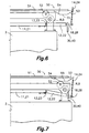
- the mechanism 50 includes a pair of stop sets 51, 55, fixed separate on the stationary structure in positions adapted to guide respective maintaining wheels 52 mounted on the leaf 2 ends above respectively the wheels 8, 9. Both stop sets 51, 55 and their respective maintaining wheels 52 are analogous therefore in Fig. 6 and 7 only one of them is shown corresponding to an end of the leaf 2.
- Each stop set 51, 55 comprises a first stop 51 having the shape of a top rolling surface located with relation to the position of the maintaining wheel 52 when it is located at the highest point (Fig. 6) corresponding to the open position of the leaf 2 and to the bigger part of transition between the open position and the closed position, that is to say, while the wheels 8, 9 roll on the stationary lengths 11, 21 of the rails 10, 20.
- a second stop 55 located at a position related to the position of the maintaining wheel 52 when this later is located at the lowest point at the closed position of the leaf 2 (Fig. 7), that is to say, when the wheels 8, 9 arrived to the final ends of the moving lengths 12, 22 of the rails 10, 20 these later being inclined.
- this later has transition inclined planes 43 and 54 at its ends.
- the sliding door of this invention can include an electric engine or some other one which provides the closing and opening motion of the leaf 2.
- the spring can be replaced by any device storing potential energy.
- the sliding door can have two leaves instead of one, with corresponding constructive modifications.
Landscapes
- Wing Frames And Configurations (AREA)
- Support Devices For Sliding Doors (AREA)
- Glass Compositions (AREA)
- Lock And Its Accessories (AREA)
Claims (13)
- Schiebetür, bestehend aus einem Flügel (2), der sich in Bezug zu einer Festkonstruktion bewegt und aus mindestens zwei Laufschienen (10, 20), die zur Befestigung des erwähnten Flügels (2) und des Verschiebens desselben dienen, und zwar von einer ersten Position aus, in welcher der Flügel (2) zumindest teilweise geöffnet und von einem Türrahmen (3) getrennt ist und einer zweiten Position, in welcher der Flügel (2) geschlossen ist und gegen den erwähnten Rahmen (3) schlägt sowie sich auf dem Fußboden abstützt, dadurch gekennzeichnet, dass sie mindestens zwei Halte- und Laufschienen (10, 20) aufweist, wobei jede von ihnen ein mit der Festkonstruktion verbundenes festes Teilstück (11, 21) sowie ein bewegliches Teilstück (12, 22) aufweist, das wiederum mit einem Ende am festen Teilstück (11, 21) angeschlossen ist, sodass das bewegliche Teilstück sich zwischen einer ersten Position, die der bereits erwähnten ersten Position des Flügels (2) entspricht, und in der das bewegliche Teilstück (12, 22) in einer Linie mit dem festen Teilstück (11, 21) liegt, und einer zweiten Position, die der bereits erwähnten zweiten Position des Flügels (2) entspricht, und in der das bewegliche Teilstück (12, 22) zum festen Teilstück (11, 21) hin geneigt ist, auf-und abbewegen kann, wobei sein freies Ende einen geringeren Abstand zur Festkonstruktion der Tür aufweist und eine geringere Höhe als das Feststück (11, 21) hat.
- Schiebetür gemäß Anspruch 1, dadurch gekennzeichnet, dass der Türflügel (2) an den mindestens zwei erwähnten Halte- und Laufschienen (10, 20) mithilfe weiterer mindestens gleich vieler Roll- bzw. Schiebeelemente (8, 9) aufgehängt ist.
- Schiebetür gemäß Anspruch 2, dadurch gekennzeichnet, dass das erwähnte freie Ende des beweglichen Teilstücks (12, 22) in seinen Bewegungen zwischen der ersten und zweiten Position durch eine schräge Führung (31, 41) geführt wird, die mit der Festkonstruktion der Tür fest verbunden ist.
- Schiebetür gemäß Anspruch 3, dadurch gekennzeichnet, dass sie Hilfsmittel zur Bewegung des Türflügels (2) zwischen seiner ersten und zweiten Position aufweist.
- Schiebetür gemäß Anspruch 4, dadurch gekennzeichnet, dass diese Hilfsmittel zur Bewegung des Türflügels (2) Lageenergie-Speichermedien (19) aufweisen, welche die Energie während der Schüeßbewegung des Flügels (2) aufnehmen und diese gespeicherte Energie während des Öffnens des Flügels wieder abgeben, wobei diese Speichermedien, die die Lageenergie (19) speichern, mit dem beweglichen Teilstück (12, 22) der Halte- und Laufschiene (10, 20) verbunden sind, um dessen Kippbewegung von der zweiten in die erste Position durch Anheben des Türgewichts und von der ersten in die zweite Position durch Auffangen des Türgewichts zu unterstützen.
- Schiebetür gemäß Anspruch 5, dadurch gekennzeichnet, dass diese Hilfsmittel zur Bewegung des Türflügels (2) für jedes bewegliche Teilstück (12, 22) jeder Halte- und Laufschiene (10, 22) eine Feder aufweisen, bei der ein Ende an der Festkonstruktion der Tür und das andere Ende am freien Ende des entsprechenden beweglichen Teilstücks (12, 22) befestigt ist.
- Schiebetür gemäß Anspruch 5, dadurch gekennzeichnet, dass diese Hilfsmittel zur Bewegung des Türflügels (2) eine Feder (19) aufweisen, bei der ein Ende an der Festkonstruktion der Tür und das andere Ende am freien Ende der beweglichen Teilstücke (12, 22) der Halte- und Laufschienen (10, 20), von denen es mindestens zwei gibt, mittels gleich viel entsprechenden Kabeln (14, 24) und Umlenkrollen (16, 26) befestigt ist.
- Schiebetür gemäß Anspruch 1, dadurch gekennzeichnet, dass jedes bewegliche Teilstück (12, 22) mit dem entsprechenden festen Teilstück (11, 21) durch ein Gelenk oder eine elastische Verbindung (13, 23) gekoppelt ist.
- Schiebetür gemäß Anspruch 2, dadurch gekennzeichnet, dass sie einen Anschlag (50) aufweist, der dafür sorgt, dass die besagten Roll- bzw. Schiebeelemente (8, 9) nicht aus ihren entsprechenden Halte- und Laufschienen (10, 20) herausfahren können.
- Schiebetür gemäß Anspruch 9, dadurch gekennzeichnet, dass dieser Anschlag (50) zwei Anschlagseinheiten (51, 55) aufweist, die getrennt und in geeigneter Weise mit der Festkonstruktion verbunden sind, um entsprechende, am Flügel (2) befestigte Hilfsräder (52) in Bezug zu den Rollen (8, 9) und auf einer höheren Ebene als diese zu lenken.
- Schiebetür gemäß Anspruch 10, dadurch gekennzeichnet, dass jede Anschlagseinheit (51, 55) einen ersten Anschlag (51) aufweist, der über der entsprechenden Schiene (10, 20) liegt und in Bezug zur höchsten Stellung des Hilfsrades (52) steht sowie einen zweiten Anschlag (55), der über dem Ende des entsprechenden festen Teilstücks (12, 22) liegt und in Bezug zur tiefsten Stellung des Hilfsrades (52) steht, wobei mindestens eine schräge Übergangsfläche (54) zwischen jedem ersten und zweiten Anschlag (51, 55) existiert.
- Schiebetür gemäß Anspruch 1, dadurch gekennzeichnet, dass die Halte- und Laufschienen (10, 20) beidseitig fluchtend sind.
- Schiebetür gemäß Anspruch 1, dadurch gekennzeichnet, dass die Halte- und Laufschienen (10, 20) auf gleicher Ebene horizontal oder vertikal versetzt und teilweise überlappt sind.
Priority Applications (4)
| Application Number | Priority Date | Filing Date | Title |
|---|---|---|---|
| ES04075093T ES2270265T3 (es) | 2004-01-15 | 2004-01-15 | Puerta corredera. |
| AT04075093T ATE333559T1 (de) | 2004-01-15 | 2004-01-15 | Schiebetür |
| DE602004001572T DE602004001572D1 (de) | 2004-01-15 | 2004-01-15 | Schiebetür |
| EP04075093A EP1555369B1 (de) | 2004-01-15 | 2004-01-15 | Schiebetür |
Applications Claiming Priority (1)
| Application Number | Priority Date | Filing Date | Title |
|---|---|---|---|
| EP04075093A EP1555369B1 (de) | 2004-01-15 | 2004-01-15 | Schiebetür |
Publications (2)
| Publication Number | Publication Date |
|---|---|
| EP1555369A1 EP1555369A1 (de) | 2005-07-20 |
| EP1555369B1 true EP1555369B1 (de) | 2006-07-19 |
Family
ID=34610204
Family Applications (1)
| Application Number | Title | Priority Date | Filing Date |
|---|---|---|---|
| EP04075093A Expired - Lifetime EP1555369B1 (de) | 2004-01-15 | 2004-01-15 | Schiebetür |
Country Status (4)
| Country | Link |
|---|---|
| EP (1) | EP1555369B1 (de) |
| AT (1) | ATE333559T1 (de) |
| DE (1) | DE602004001572D1 (de) |
| ES (1) | ES2270265T3 (de) |
Families Citing this family (4)
| Publication number | Priority date | Publication date | Assignee | Title |
|---|---|---|---|---|
| JP6325503B2 (ja) | 2015-10-26 | 2018-05-16 | ファナック株式会社 | 引戸の跳ね返り抑制機構 |
| DE102016123802A1 (de) * | 2016-12-08 | 2018-06-14 | Maco Technologie Gmbh | Laufschiene |
| DE102019132398B4 (de) * | 2018-12-20 | 2025-12-04 | Huga Kg | Schiebetür |
| DE102021104797A1 (de) | 2021-03-01 | 2022-09-01 | Landert Group Ag | Öffnungsunterstützung |
Family Cites Families (2)
| Publication number | Priority date | Publication date | Assignee | Title |
|---|---|---|---|---|
| AT405317B (de) * | 1997-05-13 | 1999-07-26 | Woess Franz | Schiebetür |
| JP3220859B2 (ja) * | 1999-06-08 | 2001-10-22 | 株式会社シブタニ | ドア装置 |
-
2004
- 2004-01-15 AT AT04075093T patent/ATE333559T1/de not_active IP Right Cessation
- 2004-01-15 DE DE602004001572T patent/DE602004001572D1/de not_active Expired - Lifetime
- 2004-01-15 ES ES04075093T patent/ES2270265T3/es not_active Expired - Lifetime
- 2004-01-15 EP EP04075093A patent/EP1555369B1/de not_active Expired - Lifetime
Also Published As
| Publication number | Publication date |
|---|---|
| EP1555369A1 (de) | 2005-07-20 |
| ES2270265T3 (es) | 2007-04-01 |
| ATE333559T1 (de) | 2006-08-15 |
| DE602004001572D1 (de) | 2006-08-31 |
Similar Documents
| Publication | Publication Date | Title |
|---|---|---|
| JP6064244B2 (ja) | 特に自動車庫用のセクション式ドア | |
| US20040177934A1 (en) | Garage door movement apparatus | |
| US20230265705A1 (en) | A door operator system | |
| US9359802B2 (en) | Garage door drive apparatus | |
| EP1555369B1 (de) | Schiebetür | |
| PL184344B1 (pl) | Brama sekcyjna | |
| US6289966B1 (en) | Door | |
| WO1995016844A1 (en) | Door mounting system | |
| KR102738928B1 (ko) | 반자동 행거식 3연동도어 | |
| WO2000061904A3 (en) | Garage door opening/closing system | |
| EP1366261B1 (de) | Vorrichtung bei türanordnung | |
| JP4410750B2 (ja) | 横移動式シャッター装置 | |
| FI91986B (fi) | Kääntölaite nostolamelliovien yhteydessä | |
| CN223075460U (zh) | 一种平移门 | |
| JP3594240B2 (ja) | 引き違い戸装置 | |
| KR102833725B1 (ko) | 반자동형 슬라이딩 도어 시스템 | |
| EP1076144A3 (de) | Lamellentor | |
| JP2981227B1 (ja) | オ―バ―ヘッドドア | |
| JP3430357B2 (ja) | ドアの開閉装置 | |
| GB2034790A (en) | Bi-panel overhead garage door | |
| EP1748136A1 (de) | Führungssystem für Sektionaltore | |
| RU1819962C (ru) | Ворота дл въезда на хоккейное поле | |
| US20090249696A1 (en) | Top lift overhead door assembly | |
| CA2568048A1 (en) | Track system arrangement for low-headroom | |
| KR200204446Y1 (ko) | 전동차의 출입구 스텝장치 |
Legal Events
| Date | Code | Title | Description |
|---|---|---|---|
| PUAI | Public reference made under article 153(3) epc to a published international application that has entered the european phase |
Free format text: ORIGINAL CODE: 0009012 |
|
| AK | Designated contracting states |
Kind code of ref document: A1 Designated state(s): AT BE BG CH CY CZ DE DK EE ES FI FR GB GR HU IE IT LI LU MC NL PT RO SE SI SK TR |
|
| AX | Request for extension of the european patent |
Extension state: AL LT LV MK |
|
| RIN1 | Information on inventor provided before grant (corrected) |
Inventor name: GUILERA NUBIOLA, JOSE MARIA |
|
| 17P | Request for examination filed |
Effective date: 20051026 |
|
| RIN1 | Information on inventor provided before grant (corrected) |
Inventor name: GUILERA NUBIOLA, JOSE MARIA |
|
| GRAP | Despatch of communication of intention to grant a patent |
Free format text: ORIGINAL CODE: EPIDOSNIGR1 |
|
| AKX | Designation fees paid |
Designated state(s): AT BE BG CH CY CZ DE DK EE ES FI FR GB GR HU IE IT LI LU MC NL PT RO SE SI SK TR |
|
| GRAS | Grant fee paid |
Free format text: ORIGINAL CODE: EPIDOSNIGR3 |
|
| GRAA | (expected) grant |
Free format text: ORIGINAL CODE: 0009210 |
|
| AK | Designated contracting states |
Kind code of ref document: B1 Designated state(s): AT BE BG CH CY CZ DE DK EE ES FI FR GB GR HU IE IT LI LU MC NL PT RO SE SI SK TR |
|
| PG25 | Lapsed in a contracting state [announced via postgrant information from national office to epo] |
Ref country code: IT Free format text: LAPSE BECAUSE OF FAILURE TO SUBMIT A TRANSLATION OF THE DESCRIPTION OR TO PAY THE FEE WITHIN THE PRESCRIBED TIME-LIMIT;WARNING: LAPSES OF ITALIAN PATENTS WITH EFFECTIVE DATE BEFORE 2007 MAY HAVE OCCURRED AT ANY TIME BEFORE 2007. THE CORRECT EFFECTIVE DATE MAY BE DIFFERENT FROM THE ONE RECORDED. Effective date: 20060719 Ref country code: RO Free format text: LAPSE BECAUSE OF FAILURE TO SUBMIT A TRANSLATION OF THE DESCRIPTION OR TO PAY THE FEE WITHIN THE PRESCRIBED TIME-LIMIT Effective date: 20060719 Ref country code: SK Free format text: LAPSE BECAUSE OF FAILURE TO SUBMIT A TRANSLATION OF THE DESCRIPTION OR TO PAY THE FEE WITHIN THE PRESCRIBED TIME-LIMIT Effective date: 20060719 Ref country code: SI Free format text: LAPSE BECAUSE OF FAILURE TO SUBMIT A TRANSLATION OF THE DESCRIPTION OR TO PAY THE FEE WITHIN THE PRESCRIBED TIME-LIMIT Effective date: 20060719 Ref country code: FI Free format text: LAPSE BECAUSE OF FAILURE TO SUBMIT A TRANSLATION OF THE DESCRIPTION OR TO PAY THE FEE WITHIN THE PRESCRIBED TIME-LIMIT Effective date: 20060719 Ref country code: CZ Free format text: LAPSE BECAUSE OF FAILURE TO SUBMIT A TRANSLATION OF THE DESCRIPTION OR TO PAY THE FEE WITHIN THE PRESCRIBED TIME-LIMIT Effective date: 20060719 Ref country code: AT Free format text: LAPSE BECAUSE OF FAILURE TO SUBMIT A TRANSLATION OF THE DESCRIPTION OR TO PAY THE FEE WITHIN THE PRESCRIBED TIME-LIMIT Effective date: 20060719 Ref country code: BE Free format text: LAPSE BECAUSE OF FAILURE TO SUBMIT A TRANSLATION OF THE DESCRIPTION OR TO PAY THE FEE WITHIN THE PRESCRIBED TIME-LIMIT Effective date: 20060719 Ref country code: NL Free format text: LAPSE BECAUSE OF FAILURE TO SUBMIT A TRANSLATION OF THE DESCRIPTION OR TO PAY THE FEE WITHIN THE PRESCRIBED TIME-LIMIT Effective date: 20060719 |
|
| REG | Reference to a national code |
Ref country code: GB Ref legal event code: FG4D |
|
| REG | Reference to a national code |
Ref country code: CH Ref legal event code: EP |
|
| REG | Reference to a national code |
Ref country code: IE Ref legal event code: FG4D |
|
| REF | Corresponds to: |
Ref document number: 602004001572 Country of ref document: DE Date of ref document: 20060831 Kind code of ref document: P |
|
| PG25 | Lapsed in a contracting state [announced via postgrant information from national office to epo] |
Ref country code: SE Free format text: LAPSE BECAUSE OF FAILURE TO SUBMIT A TRANSLATION OF THE DESCRIPTION OR TO PAY THE FEE WITHIN THE PRESCRIBED TIME-LIMIT Effective date: 20061019 Ref country code: BG Free format text: LAPSE BECAUSE OF FAILURE TO SUBMIT A TRANSLATION OF THE DESCRIPTION OR TO PAY THE FEE WITHIN THE PRESCRIBED TIME-LIMIT Effective date: 20061019 Ref country code: DK Free format text: LAPSE BECAUSE OF FAILURE TO SUBMIT A TRANSLATION OF THE DESCRIPTION OR TO PAY THE FEE WITHIN THE PRESCRIBED TIME-LIMIT Effective date: 20061019 |
|
| PG25 | Lapsed in a contracting state [announced via postgrant information from national office to epo] |
Ref country code: DE Free format text: LAPSE BECAUSE OF FAILURE TO SUBMIT A TRANSLATION OF THE DESCRIPTION OR TO PAY THE FEE WITHIN THE PRESCRIBED TIME-LIMIT Effective date: 20061020 |
|
| REG | Reference to a national code |
Ref country code: CH Ref legal event code: NV Representative=s name: RITSCHER & PARTNER AG |
|
| PG25 | Lapsed in a contracting state [announced via postgrant information from national office to epo] |
Ref country code: PT Free format text: LAPSE BECAUSE OF FAILURE TO SUBMIT A TRANSLATION OF THE DESCRIPTION OR TO PAY THE FEE WITHIN THE PRESCRIBED TIME-LIMIT Effective date: 20061219 |
|
| NLV1 | Nl: lapsed or annulled due to failure to fulfill the requirements of art. 29p and 29m of the patents act | ||
| PG25 | Lapsed in a contracting state [announced via postgrant information from national office to epo] |
Ref country code: IE Free format text: LAPSE BECAUSE OF NON-PAYMENT OF DUE FEES Effective date: 20070115 |
|
| PG25 | Lapsed in a contracting state [announced via postgrant information from national office to epo] |
Ref country code: MC Free format text: LAPSE BECAUSE OF NON-PAYMENT OF DUE FEES Effective date: 20070131 |
|
| ET | Fr: translation filed | ||
| REG | Reference to a national code |
Ref country code: CH Ref legal event code: NV Representative=s name: BOVARD AG PATENTANWAELTE |
|
| REG | Reference to a national code |
Ref country code: ES Ref legal event code: FG2A Ref document number: 2270265 Country of ref document: ES Kind code of ref document: T3 |
|
| PLBE | No opposition filed within time limit |
Free format text: ORIGINAL CODE: 0009261 |
|
| STAA | Information on the status of an ep patent application or granted ep patent |
Free format text: STATUS: NO OPPOSITION FILED WITHIN TIME LIMIT |
|
| 26N | No opposition filed |
Effective date: 20070420 |
|
| REG | Reference to a national code |
Ref country code: ES Ref legal event code: PC2A |
|
| PG25 | Lapsed in a contracting state [announced via postgrant information from national office to epo] |
Ref country code: GR Free format text: LAPSE BECAUSE OF FAILURE TO SUBMIT A TRANSLATION OF THE DESCRIPTION OR TO PAY THE FEE WITHIN THE PRESCRIBED TIME-LIMIT Effective date: 20061020 |
|
| PG25 | Lapsed in a contracting state [announced via postgrant information from national office to epo] |
Ref country code: EE Free format text: LAPSE BECAUSE OF FAILURE TO SUBMIT A TRANSLATION OF THE DESCRIPTION OR TO PAY THE FEE WITHIN THE PRESCRIBED TIME-LIMIT Effective date: 20060719 |
|
| REG | Reference to a national code |
Ref country code: CH Ref legal event code: PUE Owner name: MANUSA GEST, S.L. Free format text: GUILERA NUBIOLA, JOSE MARIA#VIA CARA, 13#BREGONZOSSA (TI) (CH) -TRANSFER TO- MANUSA GEST, S.L.#VIA AUGUSTA, 71-73 EDIFICIO DE OFICINAS TESTA - 10, PLANTA 4?#C.P. 08006 SANT CUGAT DEL VALLES (ES) |
|
| REG | Reference to a national code |
Ref country code: GB Ref legal event code: 732E Free format text: REGISTERED BETWEEN 20090122 AND 20090128 |
|
| PG25 | Lapsed in a contracting state [announced via postgrant information from national office to epo] |
Ref country code: CY Free format text: LAPSE BECAUSE OF FAILURE TO SUBMIT A TRANSLATION OF THE DESCRIPTION OR TO PAY THE FEE WITHIN THE PRESCRIBED TIME-LIMIT Effective date: 20060719 Ref country code: LU Free format text: LAPSE BECAUSE OF NON-PAYMENT OF DUE FEES Effective date: 20070115 |
|
| PG25 | Lapsed in a contracting state [announced via postgrant information from national office to epo] |
Ref country code: HU Free format text: LAPSE BECAUSE OF FAILURE TO SUBMIT A TRANSLATION OF THE DESCRIPTION OR TO PAY THE FEE WITHIN THE PRESCRIBED TIME-LIMIT Effective date: 20070120 Ref country code: TR Free format text: LAPSE BECAUSE OF FAILURE TO SUBMIT A TRANSLATION OF THE DESCRIPTION OR TO PAY THE FEE WITHIN THE PRESCRIBED TIME-LIMIT Effective date: 20060719 |
|
| REG | Reference to a national code |
Ref country code: CH Ref legal event code: PFA Owner name: MANUSA GEST, S.L. Free format text: MANUSA GEST, S.L.#VIA AUGUSTA, 71-73 EDIFICIO DE OFICINAS TESTA - 10, PLANTA 4?#C.P. 08006 SANT CUGAT DEL VALLES (ES) -TRANSFER TO- MANUSA GEST, S.L.#VIA AUGUSTA, 71-73 EDIFICIO DE OFICINAS TESTA - 10, PLANTA 4?#C.P. 08006 SANT CUGAT DEL VALLES (ES) |
|
| PGFP | Annual fee paid to national office [announced via postgrant information from national office to epo] |
Ref country code: IT Payment date: 20120127 Year of fee payment: 9 |
|
| PGFP | Annual fee paid to national office [announced via postgrant information from national office to epo] |
Ref country code: ES Payment date: 20130123 Year of fee payment: 10 Ref country code: CH Payment date: 20130129 Year of fee payment: 10 Ref country code: GB Payment date: 20130204 Year of fee payment: 10 Ref country code: FR Payment date: 20130222 Year of fee payment: 10 |
|
| REG | Reference to a national code |
Ref country code: CH Ref legal event code: PL |
|
| GBPC | Gb: european patent ceased through non-payment of renewal fee |
Effective date: 20140115 |
|
| PG25 | Lapsed in a contracting state [announced via postgrant information from national office to epo] |
Ref country code: CH Free format text: LAPSE BECAUSE OF NON-PAYMENT OF DUE FEES Effective date: 20140131 Ref country code: LI Free format text: LAPSE BECAUSE OF NON-PAYMENT OF DUE FEES Effective date: 20140131 |
|
| REG | Reference to a national code |
Ref country code: FR Ref legal event code: ST Effective date: 20140930 |
|
| PG25 | Lapsed in a contracting state [announced via postgrant information from national office to epo] |
Ref country code: GB Free format text: LAPSE BECAUSE OF NON-PAYMENT OF DUE FEES Effective date: 20140115 Ref country code: FR Free format text: LAPSE BECAUSE OF NON-PAYMENT OF DUE FEES Effective date: 20140131 |
|
| PG25 | Lapsed in a contracting state [announced via postgrant information from national office to epo] |
Ref country code: IT Free format text: LAPSE BECAUSE OF NON-PAYMENT OF DUE FEES Effective date: 20140115 |
|
| PG25 | Lapsed in a contracting state [announced via postgrant information from national office to epo] |
Ref country code: ES Free format text: LAPSE BECAUSE OF NON-PAYMENT OF DUE FEES Effective date: 20140116 |