EP1555168A1 - Dispositif pour proteger les jambes d'un occupan de vehicule - Google Patents
Dispositif pour proteger les jambes d'un occupan de vehicule Download PDFInfo
- Publication number
- EP1555168A1 EP1555168A1 EP05000484A EP05000484A EP1555168A1 EP 1555168 A1 EP1555168 A1 EP 1555168A1 EP 05000484 A EP05000484 A EP 05000484A EP 05000484 A EP05000484 A EP 05000484A EP 1555168 A1 EP1555168 A1 EP 1555168A1
- Authority
- EP
- European Patent Office
- Prior art keywords
- airbag
- projecting member
- leg
- protection device
- folded
- Prior art date
- Legal status (The legal status is an assumption and is not a legal conclusion. Google has not performed a legal analysis and makes no representation as to the accuracy of the status listed.)
- Granted
Links
Images


Classifications
-
- B—PERFORMING OPERATIONS; TRANSPORTING
- B60—VEHICLES IN GENERAL
- B60R—VEHICLES, VEHICLE FITTINGS, OR VEHICLE PARTS, NOT OTHERWISE PROVIDED FOR
- B60R21/00—Arrangements or fittings on vehicles for protecting or preventing injuries to occupants or pedestrians in case of accidents or other traffic risks
- B60R21/02—Occupant safety arrangements or fittings, e.g. crash pads
- B60R21/16—Inflatable occupant restraints or confinements designed to inflate upon impact or impending impact, e.g. air bags
- B60R21/23—Inflatable members
- B60R21/231—Inflatable members characterised by their shape, construction or spatial configuration
-
- B—PERFORMING OPERATIONS; TRANSPORTING
- B60—VEHICLES IN GENERAL
- B60R—VEHICLES, VEHICLE FITTINGS, OR VEHICLE PARTS, NOT OTHERWISE PROVIDED FOR
- B60R21/00—Arrangements or fittings on vehicles for protecting or preventing injuries to occupants or pedestrians in case of accidents or other traffic risks
- B60R21/02—Occupant safety arrangements or fittings, e.g. crash pads
- B60R21/16—Inflatable occupant restraints or confinements designed to inflate upon impact or impending impact, e.g. air bags
- B60R21/20—Arrangements for storing inflatable members in their non-use or deflated condition; Arrangement or mounting of air bag modules or components
- B60R21/205—Arrangements for storing inflatable members in their non-use or deflated condition; Arrangement or mounting of air bag modules or components in dashboards
- B60R21/206—Arrangements for storing inflatable members in their non-use or deflated condition; Arrangement or mounting of air bag modules or components in dashboards in the lower part of dashboards, e.g. for protecting the knees
-
- B—PERFORMING OPERATIONS; TRANSPORTING
- B60—VEHICLES IN GENERAL
- B60R—VEHICLES, VEHICLE FITTINGS, OR VEHICLE PARTS, NOT OTHERWISE PROVIDED FOR
- B60R21/00—Arrangements or fittings on vehicles for protecting or preventing injuries to occupants or pedestrians in case of accidents or other traffic risks
- B60R21/02—Occupant safety arrangements or fittings, e.g. crash pads
- B60R21/16—Inflatable occupant restraints or confinements designed to inflate upon impact or impending impact, e.g. air bags
- B60R21/23—Inflatable members
- B60R21/237—Inflatable members characterised by the way they are folded
-
- B—PERFORMING OPERATIONS; TRANSPORTING
- B60—VEHICLES IN GENERAL
- B60R—VEHICLES, VEHICLE FITTINGS, OR VEHICLE PARTS, NOT OTHERWISE PROVIDED FOR
- B60R21/00—Arrangements or fittings on vehicles for protecting or preventing injuries to occupants or pedestrians in case of accidents or other traffic risks
- B60R21/02—Occupant safety arrangements or fittings, e.g. crash pads
- B60R21/16—Inflatable occupant restraints or confinements designed to inflate upon impact or impending impact, e.g. air bags
- B60R21/23—Inflatable members
- B60R21/231—Inflatable members characterised by their shape, construction or spatial configuration
- B60R2021/23169—Inflatable members characterised by their shape, construction or spatial configuration specially adapted for knee protection
-
- B—PERFORMING OPERATIONS; TRANSPORTING
- B60—VEHICLES IN GENERAL
- B60R—VEHICLES, VEHICLE FITTINGS, OR VEHICLE PARTS, NOT OTHERWISE PROVIDED FOR
- B60R21/00—Arrangements or fittings on vehicles for protecting or preventing injuries to occupants or pedestrians in case of accidents or other traffic risks
- B60R21/02—Occupant safety arrangements or fittings, e.g. crash pads
- B60R21/16—Inflatable occupant restraints or confinements designed to inflate upon impact or impending impact, e.g. air bags
- B60R21/23—Inflatable members
- B60R21/231—Inflatable members characterised by their shape, construction or spatial configuration
- B60R21/233—Inflatable members characterised by their shape, construction or spatial configuration comprising a plurality of individual compartments; comprising two or more bag-like members, one within the other
- B60R2021/23316—Inner seams, e.g. creating separate compartments or used as tethering means
Definitions
- the present invention relates to leg-protection devices for protecting the legs of vehicle occupants when vehicles collide, and more specifically it relates to a leg-protection device for an occupant of a driver's seat.
- a typical leg-protection device for protecting the legs of a vehicle occupant when the vehicle collides includes a case disposed behind an instrument panel placed in front of a seat, an airbag contained in the case, and a gas generator for inflating the airbag.
- the gas generator When the vehicle collides, the gas generator is activated and discharges gas. The discharged gas is supplied to the airbag and the airbag inflates into a space between the instrument panel and the occupant's legs to protect the occupant's legs.
- JP-A-2003-226215 discloses a structure including this type of leg-protection device below a steering column.
- an airbag inflates along a bottom face of a steering-column cover when the vehicle collides, and the inflated airbag protects the legs of the driver.
- a keyhole is often provided in a side face of the steering-column cover. Therefore, when a key chain or the like (e.g., an accessory or another key) is attached to a key which is inserted in the keyhole, the key chain or the like may hang down to a space below the steering-column cover. In such a case, the key chain or the like may interfere with the airbag when the airbag inflates in the space below the steering-column cover.
- a key chain or the like e.g., an accessory or another key
- An object of the present invention is to provide a leg-protection device for a vehicle occupant, the leg-protection device including an airbag which inflates in a space below a steering column (steering-column cover) without being interfered with by a key chain or the like.
- the leg-protection device for the vehicle occupant includes the projecting member which projects from the front end of the airbag in the inflating direction when the airbag inflates. Therefore, even if a key chain or the like hangs down to below the steering-column cover when the airbag inflates along the bottom face of the steering-column cover, the projecting member comes into contact with the key chain or the like and pushes it away before the airbag comes into contact with the key chain or the like. Accordingly, the airbag is prevented from being interfered with by the key chain or the like which hangs down to below the steering-column cover when the airbag inflates along the bottom face of the steering-column cover.
- the projecting member is formed integrally with the airbag (integrally with panels of cloth or the like forming the airbag), and therefore the projecting member is easily provided.
- the projecting member may be a small, tab-shaped member which can push away the key chain or the like.
- the projecting member is folded on the side facing the occupant or on the opposite side.
- the size of the folded airbag can be reduced.
- the projecting member may be folded in an accordion style, a roll style, or a combination of the accordion style and the roll style.
- the airbag is preferably rolled from the top to the bottom such that the side of the airbag opposite to the occupant faces the center of the roll.
- the rolled airbag deploys upward while rotating toward the occupant when viewed from above. Because of this rotation, when the airbag is unrolled to the top, the top edge of the airbag moves upward along a curve in the direction toward the occupant. At this time, the front-end portion of the projecting member is pushed upward by the top edge of the airbag and projects beyond the top edge of the airbag.
- the airbag In the case in which the airbag is rolled from the top to the bottom such that the side of the airbag opposite to the occupant faces the center of the roll, the airbag is unrolled such that it rotates on the front portions of the occupant's legs when it inflates. Therefore, the airbag smoothly deploys without being caught by the front portions of the occupant's legs.
- a cover cloth for covering the projecting member in a folded state may be provided.
- the projecting member is prevented from being unfolded and the airbag device is easily assembled. Accordingly, the folded shape of the projecting member is reliably maintained in the airbag device.
- the airbag inflates the projecting member is covered by the cover cloth until the shape of the airbag becomes close to that in the fully deployed state, and bounces upward to push away the key holder or the like at the final phase of the inflation.
- an upper portion of the airbag is folded inward such that the upper portion is tucked in, and the tab-shaped projecting member may be folded together with the upper portion of the airbag.
- a pleat formed by folding the upper portion of the airbag inward is pushed up toward the outside of the airbag when the airbag inflates, and thereby pushes the projecting member such that the projecting member bounces upward to push the key chain or the like.
- the projecting member is formed independently of the airbag (independently of panels of cloth or the like forming the airbag), and therefore the projecting member can be attached at any desired position.
- the projecting member is tab-shaped and has a base end attached to the airbag on the side facing the occupant (preferably at a position near the top edge) and a front end disposed on the side opposite to the occupant such that the projecting member extends over an upper portion of the airbag.
- the airbag is preferably rolled from the top to the bottom such that the side of the airbag opposite to the occupant faces the center of the roll.
- the rolled airbag deploys upward while rotating toward the occupant when viewed from above. Because of this rotation, when the airbag is unrolled to the top, the top edge of the airbag moves upward along a curve in the direction toward the occupant. At this time, the front-end portion of the projecting member is pushed upward by the top edge of the airbag and projects beyond the top edge of the airbag.
- the airbag In the case in which the airbag is rolled from the top to the bottom such that the side of the airbag opposite to the occupant faces the center of the roll, the airbag is unrolled such that it rotates on the front portions of the occupant's legs when it inflates. Therefore, the airbag smoothly deploys without being caught by the front portions of the occupant's legs.
- a cover cloth for covering the projecting member in a folded state may be provided on the side opposite to the occupant.
- the projecting member is prevented from being unfolded and the airbag device is easily assembled.
- the folded shape of the airbag is also reliably maintained in the airbag device.
- the projecting member is tab-shaped and has a base end attached to the airbag on the side opposite to the occupant and a front end disposed on the side facing the occupant such that the projecting member extends over an upper portion of the airbag.
- a cover cloth for covering the projecting member in a folded state may be provided on the side facing the occupant to maintain the folded shape of the projecting member.
- the upper portion of the airbag may be folded inward such that the upper portion is tucked in.
- a pleat formed by folding the upper portion of the airbag inward is pushed up toward the outside of the airbag when the airbag inflates, and thereby pushes the projecting member such that the projecting member bounces upward beyond the top edge of the airbag.
- the projecting member which extends over the upper portion may be folded in an accordion style, a roll style, or a combination of the accordion style and the roll style.
- Fig. 1(a) is a front view of an airbag included in a leg-protection device for a vehicle occupant according to an embodiment of the present invention
- Fig. 1(b) is an enlarged view of a part denoted by B in Fig. 1(a)
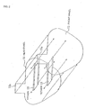
- Fig. 2 is an exploded perspective view of the airbag.
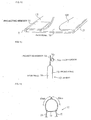
- Fig. 3(a) is a front view showing the airbag in a partially folded state
- Fig. 3(b) is a sectional view of Fig. 3(a) taken along line B-B
- Fig. 3(c) is a perspective view showing the state in which a projecting member is bent.
- Figs. 4 to 6 are vertical sectional views showing the manner in which the airbag inflates.
- a "left-right direction" refers to the width direction of the vehicle, and is the same as the left-right direction in Fig. 1(a).
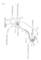
- an instrument panel 1 is provided in front of a driver's seat of a vehicle, and a steering-column cover 2 is provided to cover a steering column (not shown) which projects from the instrument panel 1.
- a steering wheel 3 is fixed to a steering shaft (not shown) which projects from the steering column.
- a keyhole 4 is provided in a left side (as seen from the driver) of the steering-column cover 2.
- a key 5 is inserted in the keyhole 4, and a key chain 6 (shown as another key in Figs. 4 to 6) is attached to the key 5.
- the key chain 6 is hung down beyond the bottom face of the steering-column cover 2 in a normal state (state in which the key chain 6 is not pushed up by a projecting member 14 as described below).
- a leg-protection device 10 for a vehicle occupant is installed below the steering-column cover 2.
- the leg-protection device 10 includes a container-shaped case 11 having an opening (no reference numeral) in the front face which faces the occupant, an airbag 12 connected to the case 11, and a gas generator 13 for inflating the airbag 12.
- the case 11 is fitted in an airbag-inflation opening 7 formed in the instrument panel 1 at a position below the steering-column cover 2.
- the airbag 12 is contained in the case 11 in a folded state, and a lid (not shown) is attached to cover the opening in the front face of the case 11 containing the folded airbag 12.
- the lid opens by being pushed by the airbag 12 and uncovers the airbag-inflation opening 7.
- the airbag 12 receives gas from the gas generator 13, starts inflating through the airbag-inflation opening 7 toward the front of the instrument panel 1, and deploys upward along the instrument panel 1 in the region below the steering-column cover 2 and then along the bottom face of the steering-column cover 2, as shown in Figs. 4 to 6.
- the airbag 12 is shaped such that the size thereof in the left-right direction (the width direction of the vehicle) increases toward the top, and is larger than the size of the steering-column cover 2 in the left-right direction at the top of the airbag 12.
- the airbag 12 inflates along the bottom face of the steering-column cover 2, an upper portion of the airbag 12 faces the bottom face of the steering-column cover 2 at the central region thereof, and extends beyond the left and right sides of the steering-column cover 2 at the left and right regions thereof.
- the airbag 12 has the projecting member 14 which projects upward from the top edge of the airbag 12 when the airbag 12 inflates.
- the projecting member 14 is provided on the top edge of the airbag 12. Therefore, as shown in Fig. 6, when the airbag 12 inflates along the bottom surface of the steering column cover 2, the projecting member 14 projects upward along the left side face of the steering column cover 2, that is, along the side face in which the keyhole 4 is formed.
- the outer structure of the airbag 12 is constructed of a front panel 15 which faces the occupant and a rear panel 16 which faces the instrument panel 1 (steering-column cover 2), as shown in Fig. 2.
- the front panel 15 and the rear panel 16 are sewn together at the periphery thereof to form a bag shape.
- Reference numeral 17 denotes the seam at the periphery.
- the projecting member 14 is formed integrally with the airbag 12. More specifically, as shown in Fig. 2, in the present embodiment, projecting tabs 15a and 16a project from the top edges of the front panel 15 and the rear panel 16, respectively, in left regions thereof, and the projecting member 14 is formed by sewing them together, as shown in Fig. 1(b).
- Reference numeral 18 denotes the seams between the projecting tabs 15a and 16a. In the present embodiment, the seams 18 extend along the diagonal lines of the projecting tabs 15a and 16a in the shape of the letter 'X'.
- the airbag 12 is provided with tethers 19 which connect the front panel 15 and the rear panel 16 so as to limit the inflation of the airbag 12 in the thickness direction thereof.
- Reference numeral 20 denotes seams with which the tethers 19 are sewn to the front panel 15 and the rear panel 16.
- the tethers 19 are continuous in the left-right direction, and a plurality of (two in the present embodiment) tethers 19 are arranged in the vertical direction. The left and right ends of each tether 19 are separated from the left and right edges of the airbag 12, and spaces for communicating air are provided between them.
- tethers 19 are not shown in Figs. 4 to 6.
- the gas generator 13 is disposed in the airbag 12. More specifically, a stud bolt 13a which projects from a holder (no reference numeral) of the gas generator 13 is inserted through a lower potion of the rear panel 16 of the airbag 12 and a rear wall of the case 11 and is screwed into a nut 13b. Thus, due to the engagement between the stud bolt 13a and the nut 13b, the gas generator 13 is fixed to the case 11 and the lower portion of the rear panel 16 of the airbag 12 is clamped between the holder of the gas generator 13 and the rear wall of the case 11.
- the airbag 12 when the airbag 12 is folded, first, the airbag 12 is pulled out from the case 11 and is spread. Then, as shown in Figs. 3(a) and 3(b), left and right portions 12L and 12R of the airbag 12 are folded along vertical folding lines 21 and 21 such that the rear panel 16 faces inward. Then, as shown in Fig. 3(c), the projecting member 14 is bent over to the side of the rear panel 16 along the bottom side thereof and is laminated on the folded left portion 12L. Then, the airbag 12 is rolled from the top to the bottom, and is put into the case 11 in the rolled state. At this time, the airbag 12 is rolled such that the rear panel 16 faces the center of the roll and the front panel 15 faces outward.
- the gas generator 13 discharges the gas and the airbag 12 starts to inflate. More specifically, the airbag 12 opens the lid by pushing it, starts inflating through the airbag-inflation opening 7 toward the front of the instrument panel 1, and deploys upward along the front face of the instrument panel 1.
- the airbag 12 As the airbag 12 deploys upward, it is unrolled in the manner shown in Figs. 4 and 5. Then, when the airbag 12 is unrolled to the top, the left and right portions 12L and 12R, which have been folded such that the rear panel 16 faces inward, start to deploy by pivoting around the vertical folding lines 21. Accordingly, the projecting member 14, which has been laminated on the left portion 12L, bounces upward when the left portion 12L deploys, and thus the projecting member 14 projects upward from the top edge of the airbag 12, as shown in Fig. 6.
- the projecting member 14 projects upward from the top edge of the airbag 12, even if the key chain 6 hangs down to below the steering-column cover 2 when the airbag 12 deploys along the bottom face of the steering-column cover 2, the projecting member 14 comes into contact with the key chain 6 and pushes the key chain 6 upward before the airbag 12 comes into contact with the key chain 6, as shown in Figs. 5 and 6. Accordingly, the airbag 12 is prevented from being interfered with by the key chain 6 when the airbag 12 deploys in the space below the steering-column cover 2.
- the moving speed of the key chain 6 is reduced compared to the case in which the airbag 12 directly pushes the key chain 6 upward when the airbag 12 inflates.
- the airbag 12 receives a repulsive force in the direction opposite to the inflating direction thereof via the projecting member 14, and therefore the inflation speed of the airbag 12 immediately before the end of the inflation is also reduced.
- the projecting member 14 is bent over to the side of the rear panel 16 when the airbag 12 is folded.
- the method for folding the projecting member 14 is not limited to this.
- Figs. 7(a), 7(b), 8, and 10 show other methods for folding the projecting member.
- Figs. 7(a), 7(b), and 10 are vertical sectional views of the upper portion of the airbag
- Fig. 8(a) is a front view of the airbag
- Fig. 8(b) is a sectional view of Fig. 8(a) taken along line B-B.
- the projecting member 14 is folded from the front end to the base end in a zigzag style (accordion style). Instead of the zigzag style, the projecting member 14 may also be folded in a roll style, a winding style, etc., or a combination of different styles. In addition, the projecting member 14 may also be bent over to the side of the front panel 15 or the rear panel 16 of the airbag 12 and be disposed on the front panel 15 or the rear panel 16 in a folded manner.
- the upper portion of the airbag 12 is bent inward along horizontal folding lines 22 such that this part is tucked in and a pleat 12T is formed.
- the projecting member 14 is also tucked in with the pleat 12T.
- the pleat 12T When the airbag 12 is folded in the manner shown in Fig. 8, the pleat 12T is pushed straight up toward the outside of the airbag 12 when the airbag 12 inflates. Due to the upward movement of the pleat 12T, the projecting member 14 is pushed straight up by the pleat 12T.
- the projecting member 14 may also be folded in a zigzag style (accordion style), a roll style, etc., and then be tucked in with the pleat 12T.
- a cover cloth for covering the projecting member in a folded state may also be provided.
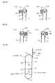
- Figs. 11(a) to 11(d) are vertical sectional views showing airbags provided with cover cloths.
- a pleat 12T is formed by folding an upper portion of an airbag 12 inward.
- a base end of a projecting member 14 is positioned on the pleat 12T, and a front end of the projecting member 14 extending from the pleat 12T is folded on the rear panel 16 in a zigzag style (accordion style), and is covered by a cover cloth 30 provided on the rear panel 16, as shown in the figure.
- the cover cloth 30 is rectangular and at least the bottom side thereof is sewn to the rear panel 16 with a seam 31. Instead of sewing, the cover cloth 30 may also be attached by heat sealing or adhesion.
- the cover cloth 30 may either be bonded to the rear panel only at the bottom side or be bonded to the bottom side and at least one of the left and right sides.
- the folded projecting member 14 is covered by the cover cloth 30, the folded shape of the projecting member 14 is maintained.
- the projecting member 14 is folded in a roll style instead of the zigzag style, and is positioned between the rear panel 16 and the cover cloth 30.
- the projecting member 14 may be folded in various styles other then the styles shown in the figure, and may also be folded in a combination of different styles.
- the projecting member 14 is disposed on the rear panel 16 of the airbag 12 in the folded state.
- the projecting member 14 is disposed on the front panel 15 in the folded state.
- the cover cloth 30 is attached to the front panel 15, and the folded projecting member 14 is positioned between the front panel 15 and the cover cloth 30 and is covered by the cover cloth 30.
- the projecting member 14 is folded in a zigzag style in Fig. 11(c), and is folded in a roll style in Fig. 11(d).
- the folding style of the projecting member 14 is not limited to them.
- the projecting member 14 is laminated on the left portion 12L of the airbag 12 in Fig. 3(c), it may also be placed between the left portion 12L of the airbag 12 and the central portion of the rear panel 16, as shown in Fig. 12.
- This embodiment is suitable for when the cover cloth 30 is provided, as shown in Fig. 11.
- the projecting member 14 is folded and is covered by the cover cloth 30, and the side portions of the airbag are folded. Then, the overall body of the airbag is folded.
- the projecting tabs 15a and 16a which project from the top edges of the front panel 15 and the rear panel 16, respectively, of the airbag 12 is sewn together with the seams 18 which extend along the diagonal lines of the projecting tabs 15a and 16a in the shape of the letter 'X'.
- the structure for bonding the projecting tabs 15a and 16a together is not limited to this.
- Figs. 9(a) to 9(c) are perspective views showing other structures for bonding projecting tabs together.
- the projecting tabs 15a and 16a are adhered to each other by applying an adhesive 25 along the bottom side (side parallel to a seam 17) and the left and right sides.
- the front panel 15 and the rear panel 16 are both provided with the projecting tabs 15a and 16a, respectively, and the projecting member 14 is formed by bonding the projecting tabs 15a and 16a together.
- a projecting tab which functions as the projecting member may also be provided on only one of the front panel 15 and the rear panel 16.
- the projecting member may also be provided with a reinforcing material for stabilizing the position and orientation of the projecting member when the projecting member pushes the key chain or the like upward.
- Fig. 13 is a sectional view of an airbag according to another embodiment of the present invention.
- a loop 14a is provided at the middle of a projecting member 14.
- Reference numeral 14b denotes a seam at the bottom of the loop 14a.
- the loop 14a is on the outwardly facing side of the projecting member 14 when the projecting member 14 is bent over to the side of the rear panel 16.
- the projecting member 14 Since the projecting member 14 has the loop 14a, the projecting member 14 comes into contact with the key chain or the like softly when the airbag 12 inflates.
- the thickness of the projecting member 14 is increased and the contact area between the projecting member 14 and the key chain or the like is increased accordingly. Therefore, the key chain or the like more easily comes into contact with the projecting member 14. In addition, the key chain or the like is more easily pushed away since the loop 14a comes into contact with it first, and the airbag 12 is reliably prevented from being interfered with by the key chain or the like.
- the seam 14b may either be formed such that it breaks or does not break when it comes into contact with the key chain or the like.
- loop 14a may also be provided.
- the loop 14a may also be provided such that it is on the outwardly facing side of the projecting member 14 when the projecting member 14 is bent over to the side of the front panel 15.
- the length between the top end of the airbag 12 to the position at which the distance between the front and rear panels in the top room is at a maximum is preferably set to about 80 mm.
- the present invention is also not limited to this.
- Fig. 15(a) is a front view of an airbag included in a leg-protection device for a vehicle occupant according to an embodiment of the present invention
- Fig. 15(b) is a sectional view of Fig. 15(a) taken along line B-B.
- Fig. 16(a) is a front view showing the airbag in a partially folded state
- Fig. 16(b) is a sectional view of Fig. 16(a) taken along line B-B
- Fig. 16(c) is a perspective view showing the state in which a flap, which functions as a projecting member, is bent.
- Figs. 17 and 18 are vertical sectional views showing the manner in which the airbag inflates.
- a "left-right direction" refers to the width direction of the vehicle, and is the same as the left-right direction in Fig. 15(a).
- an instrument panel 1 is provided in front of a driver's seat of a vehicle, and a steering-column cover 2 is provided to cover a steering column (not shown) which projects from the instrument panel 1.
- a steering wheel 3 is fixed to a steering shaft (not shown) which projects from the steering column.
- a keyhole 4 is provided in a left side (as seen from the driver) of the steering-column cover 2.
- a key 5 is inserted in the keyhole 4, and a key chain 6 (shown as another key in Figs. 17 and 18) is attached to the key 5.
- the key chain 6 hangs down beyond the bottom face of the steering-column cover 2 in a normal state (state in which the key chain 6 is not pushed up by a flap 14 which functions as the projecting member as described below).
- a leg-protection device 10 for a vehicle occupant is installed below the steering-column cover 2.
- the leg-protection device 10 includes a container-shaped case 11 having an opening (no reference numeral) in the front face which faces the occupant, an airbag 12 connected to the case 11, and a gas generator 13 for inflating the airbag 12.
- the case 11 is fitted in an airbag-inflation opening 7 formed in the instrument panel 1 at a position below the steering-column cover 2.
- the airbag 12 is contained in the case 11 in a folded state, and a lid (not shown) is attached to cover the opening in the front face of the case 11 containing the folded airbag 12.
- the lid opens by being pushed by the airbag 12 and uncovers the airbag-inflation opening 7.
- the airbag 12 receives gas from the gas generator 13, starts inflating through the airbag-inflation opening 7 toward the front of the instrument panel 1, and deploys upward along the instrument panel 1 in the region below the steering-column cover 2 and then along the bottom face of the steering-column cover 2, as shown in Figs. 17 and 18.
- the airbag 12 is shaped such that the size thereof in the left-right direction (the width direction of the vehicle) increases toward the top, and is larger than the size of the steering-column cover 2 in the left-right direction at the top of the airbag 12.
- the airbag 12 inflates along the bottom face of the steering-column cover 2, an upper portion of the airbag 12 faces the bottom face of the steering-column cover 2 at the central region thereof and extends beyond the left and right sides of the steering-column cover 2 at the left and right regions thereof.
- the airbag 12 has the flap 14 which functions as the projecting member and projects upward from the top edge of the airbag 12 (the front end of the airbag 12 in the inflating direction) when the airbag 12 inflates.
- the flap 14 is disposed on the upper left position of the airbag 12.
- the outer structure of the airbag 12 is constructed of a front panel 15 which faces the occupant and a rear panel 16 which faces the instrument panel 1 (steering-column cover 2).
- the front panel 15 and the rear panel 16 are sewn together at the periphery thereof to form a bag shape.
- Reference numeral 17 denotes the seam at the periphery.
- the flap 14 is formed independently of both the front panel 15 and the rear panel 16. One end (base end) of the flap 14 is sewn to the front panel 15 at a position near the top edge thereof, as shown in Fig. 15(b), and the other end (front end) is disposed on the side of the rear panel 16 such that the flap 14 extends over the upper portion of the airbag 12.
- Reference numeral 14s denotes the seam with which the base end of the flap 14 is sewn to the front panel 15. As shown in the figure, the front end of the flap 14 is a free end (free from the rear panel 16).
- the airbag 12 is provided with tethers 19 which connect the front panel 15 and the rear panel 16 so as to limit the inflation of the airbag 12 in the thickness direction thereof.
- Reference numeral 20 denotes seams with which the tethers 19 are sewn to the front panel 15 and the rear panel 16.
- the tethers 19 are continuous in the left-right direction, and a plurality of (two in the present embodiment) tethers 19 are arranged in the vertical direction. The left and right ends of each tether 19 are separated from the left and right edges of the airbag 12, and spaces for communicating air are provided between them.
- tethers 19 are not shown in Figs. 17 and 18.
- the gas generator 13 is disposed in the airbag 12. More specifically, a stud bolt 13a which projects from a holder (no reference numeral) of the gas generator 13 is inserted through a lower potion of the rear panel 16 of the airbag 12 and a rear wall of the case 11 and is screwed into a nut 13b. Thus, due to the engagement between the stud bolt 13a and the nut 13b, the gas generator 13 is fixed to the case 11 and the lower portion of the rear panel 16 of the airbag 12 is clamped between the holder of the gas generator 13 and the rear wall of the case 11.
- the airbag 12 when the airbag 12 is folded, first, the airbag 12 is pulled out from the case 11 and is spread. Then, as shown in Figs. 16(a) and 16(b), left and right portions 12L and 12R of the airbag 12 are folded along vertical folding lines 21 and 21 such that the rear panel 16 faces inward. Then, as shown in Fig. 16(c), the flap 14 is bent over to the side of the rear panel 16 and a front-end portion of the flap 14 is laminated on the folded left portion 12L. Then, the airbag 12 is rolled from the top to the bottom, and is put into the case 11 in the rolled state. At this time, the airbag 12 is rolled such that the rear panel 16 faces the center of the roll and the front panel 15 faces outward.
- the gas generator 13 discharges the gas and the airbag 12 starts to inflate. More specifically, the airbag 12 opens the lid by pushing it, starts inflating through the airbag-inflation opening 7 toward the front of the instrument panel 1, and deploys upward along the front face of the instrument panel 1.
- the rolled airbag 12 When viewed from above, the rolled airbag 12 deploys upward while rotating in the direction from the instrument panel 1 to the occupant. Because of this rotation, when the airbag 12 is unrolled to the top, the top edge of the airbag 12 moves upward along a curve in the direction from the instrument panel 1 toward the occupant, as shown in Figs. 17 and 18. At this time, the front-end portion of the flap 14 is pushed upward by the top edge of the airbag 12 and projects upward beyond the top edge of the airbag 12.
- the left and right portions 12L and 12R which have been folded such that the rear panel 16 faces inward, start to deploy by pivoting around the vertical folding lines 21. Accordingly, the flap 14, which has been laminated on the left portion 12L, bounces upward when the left portion 12L deploys, and thus the upward movement of the flap 14 is accelerated.
- the flap 14 projects upward from the top edge of the airbag 12, even if the key chain 6 hangs down to below the steering-column cover 2 when the airbag 12 deploys along the bottom face of the steering-column cover 2, the flap 14 comes into contact with the key chain 6 and pushes the key chain 6 upward before the airbag 12 comes into contact with the key chain 6. Accordingly, the airbag 12 is prevented from being interfered with by the key chain 6 when the airbag 12 deploys in the space below the steering-column cover 2.
- the moving speed of the key chain 6 is reduced compared to the case in which the airbag 12 directly pushes the key chain 6 upward when the airbag 12 inflates.
- the airbag 12 receives a repulsive force in the direction opposite to the inflating direction thereof via the flap 14, and therefore the inflation speed of the airbag 12 immediately before the end of the inflation is also reduced.
- the airbag 12 is rolled from the top to the bottom such that the rear panel 16 faces the center of the roll. Accordingly, when the airbag 12 inflates, it is unrolled such that it rotates on the front portions of the occupant's legs. Therefore, the airbag 12 smoothly deploys without being caught by the front portions of the occupant's legs.
- the base end of the flap 14 is attached to the front panel 15 of the airbag 12 at a position near the top edge and the front end of the flap 14 is disposed on the side of the rear panel 16.
- the arrangement of the flap 14 is not limited to this.
- the base end of the flap may also be attached to the rear panel of the airbag and the front end thereof may be disposed on the side of the front panel.
- the method for folding the airbag is also not limited to the method described above.
- Fig. 19(a) is a front view showing another method for folding the airbag
- Fig. 19(b) is a sectional view of Fig. 19(a) taken along line B-B.
- the airbag 12 when the airbag 12 is folded, first, the airbag 12 is spread and a part of the upper portion of the airbag 12 above the base end of the flap 14 (above the seam 14s) is folded inward along folding lines 22 such that this part is tucked in and a pleat 12T is formed.
- the front-end portion of the flap 14 is bent over the pleat 12T to the side of the rear panel 16.
- the airbag 12 is folded similarly to the above-described embodiment shown in Figs. 15 to 18 except for the step of folding the upper portion of the airbag 12 inward to form the pleat 12T.
- the pleat 12T When the airbag 12 in which the pleat 12T is formed by folding the upper portion thereof as above inflates, the pleat 12T is pushed straight up toward the outside of the airbag 12 due to the gas pressure in the airbag when the upper portion of the airbag inflates. Due to the upward movement of the pleat 12T, the front-end portion of the flap 14 is pushed upward and projects beyond the top edge of the airbag 12. Accordingly, the flap 14 bounces upward.
- Fig. 20(a) is a front view of an airbag 12A according to a modification of the airbag shown in Fig. 19 in which a cover cloth 30 for covering a folded flap (projecting member) 14 is provided on a rear panel 16, and Fig. 20(b) is a sectional view of Fig. 20(a) taken along line B-B.
- Fig. 21 shows sectional views of structures in which the flap 14 is folded.
- the cover cloth 30 is rectangular and at least the bottom side thereof is sewn to the rear panel 16 with a seam 31. Instead of sewing, the cover cloth 30 may also be attached by heat sealing or adhesion.
- the folded flap 14 is disposed between the cover cloth 30 and the rear panel 16, and is thereby covered by the cover cloth 30.
- the cover cloth 30 may either be sewn to the rear panel only at the bottom side or be sewn at the bottom side and at least one of the left and right sides.
- the flap 14 may be folded in an accordion style as shown in Fig. 21(a), a roll style as shown in Fig. 21(b), or a combination of the accordion style and the roll style (not shown).
- the flap 14 is attached to the front panel 15 such that it extends over the upper portion of the airbag to the side of the rear panel 16.
- a flap 14 may also be attached to a rear panel 16 such that it extends over an upper portion of an airbag 12B to the side of a front panel 15.
- a cover cloth 30 for covering the flap 14 in the folded state is attached to the front panel 15 with a seam 31.
- the flap 14 may be folded in an accordion style as shown in Fig. 22(a), a roll style as shown in Fig. 22(b), or a combination of the accordion style and the roll style (not shown).
- Fig. 23 is a sectional view of an airbag according to another embodiment of the present invention.
- a loop 14a is provided at the middle of a flap 14.
- Reference numeral 14b denotes a seam at the bottom of the loop 14a.
- the loop 14a is at the top of the flap 14 in the state in which the flap 14 extends over an upper portion of an airbag 12.
- the flap 14 Since the flap 14 has the loop 14a, the flap 14 comes into contact with the key chain or the like softly when the airbag 12 inflates.
- the thickness of the flap 14 is increased and the contact area between the flap 14 and the key chain or the like is increased accordingly. Therefore, the key chain or the like more easily comes into contact with the flap 14. In addition, the key chain or the like is more easily pushed away since the loop 14a comes into contact with it first, and the airbag is reliably prevented from being interfered with by the key chain or the like.
- the seam 14b may either be formed such that it breaks or does not break when it comes into contact with the key chain or the like.
- Two or more loops 14a may also be provided.
- the flap 14 is attached to the front panel 15 in Fig. 23, it may also be attached to the rear panel 16.
- the front-end portion of the flap 14 is laminated on the left portion 12L in Fig. 16(c), it may also be placed between the left portion 12L and the central portion of the rear panel 16, as shown in Fig. 24.
- This embodiment is suitable for when the cover cloth 30 is provided and the pleat 12T is formed by folding the upper portion of the airbag inward, as shown in Figs. 20 to 22.
- the upper portion of the airbag is folded inward and the flap 14 is bent over to the side opposite to the side at which it is attached.
- the flap 14 is folded and is covered by the cover cloth 30, and the side portions of the airbag are folded.
- the overall body of the airbag is folded.
- the present invention is not limited to these embodiments.
- the length between the top end of the airbag 12 to the position at which the distance between the front and rear panels in the top room is at a maximum is preferably set to about 80 mm.
- the present invention is also not limited to this.
Landscapes
- Engineering & Computer Science (AREA)
- Mechanical Engineering (AREA)
- Air Bags (AREA)
Applications Claiming Priority (8)
| Application Number | Priority Date | Filing Date | Title |
|---|---|---|---|
| JP2004007014 | 2004-01-14 | ||
| JP2004007013 | 2004-01-14 | ||
| JP2004007013 | 2004-01-14 | ||
| JP2004007014 | 2004-01-14 | ||
| JP2004040110 | 2004-02-17 | ||
| JP2004040110A JP2005225463A (ja) | 2004-01-14 | 2004-02-17 | 乗員脚部保護装置 |
| JP2004060880 | 2004-03-04 | ||
| JP2004060880A JP2005225464A (ja) | 2004-01-14 | 2004-03-04 | 乗員脚部保護装置 |
Publications (2)
| Publication Number | Publication Date |
|---|---|
| EP1555168A1 true EP1555168A1 (fr) | 2005-07-20 |
| EP1555168B1 EP1555168B1 (fr) | 2008-06-18 |
Family
ID=34623906
Family Applications (1)
| Application Number | Title | Priority Date | Filing Date |
|---|---|---|---|
| EP05000484A Expired - Fee Related EP1555168B1 (fr) | 2004-01-14 | 2005-01-12 | Dispositif pour proteger les jambes d'un occupan de vehicule |
Country Status (4)
| Country | Link |
|---|---|
| US (1) | US7377541B2 (fr) |
| EP (1) | EP1555168B1 (fr) |
| CN (1) | CN100417552C (fr) |
| DE (1) | DE602005007522D1 (fr) |
Cited By (3)
| Publication number | Priority date | Publication date | Assignee | Title |
|---|---|---|---|---|
| EP1759936A1 (fr) * | 2005-08-30 | 2007-03-07 | Takata Corporation | Dispositif de protection des jambes pour le conducteur |
| EP2204305A1 (fr) * | 2007-10-22 | 2010-07-07 | Ashimori Industry Co., Ltd. | Dispositif à airbag destiné à protéger les genoux |
| EP2072348A3 (fr) * | 2007-12-18 | 2013-05-22 | Autoliv Development AB | Coussin d'air pour genoux et son procédé de pliage |
Families Citing this family (9)
| Publication number | Priority date | Publication date | Assignee | Title |
|---|---|---|---|---|
| JP4063712B2 (ja) * | 2003-05-22 | 2008-03-19 | 豊田合成株式会社 | 膝保護用エアバッグ装置 |
| JP4894283B2 (ja) * | 2006-02-10 | 2012-03-14 | タカタ株式会社 | 乗員脚部拘束装置 |
| JP4235221B2 (ja) * | 2006-11-02 | 2009-03-11 | トヨタ自動車株式会社 | コラム付けニーエアバッグ装置 |
| JP4235222B2 (ja) * | 2006-11-02 | 2009-03-11 | トヨタ自動車株式会社 | コラム付けニーエアバッグ装置 |
| JP4420121B2 (ja) * | 2008-03-12 | 2010-02-24 | トヨタ自動車株式会社 | コラム付けニーエアバッグ装置 |
| DE102010030194B4 (de) * | 2010-06-17 | 2018-06-07 | Bayerische Motoren Werke Aktiengesellschaft | Knieairbaganordnung für Fahrzeuge |
| US8696019B2 (en) * | 2011-03-21 | 2014-04-15 | Tk Holdings Inc. | Knee airbag module |
| JP7087814B2 (ja) * | 2018-08-10 | 2022-06-21 | トヨタ自動車株式会社 | 車室前部構造 |
| CN113978409B (zh) * | 2020-12-23 | 2022-08-19 | 苏州天准科技股份有限公司 | 车用安全气囊的收纳方法 |
Citations (4)
| Publication number | Priority date | Publication date | Assignee | Title |
|---|---|---|---|---|
| EP0861762A1 (fr) * | 1997-02-27 | 1998-09-02 | HS Technik und Design Technische Entwicklungen GmbH | Coussin gonflable pour passager |
| DE19946477A1 (de) * | 1999-09-28 | 2001-03-29 | Takata Europ Gmbh | Airbag-Anordnung |
| EP1262378A2 (fr) * | 2001-05-21 | 2002-12-04 | Toyoda Gosei Co., Ltd. | Dispositif de sac de sécurité gonflable pour protéger les genoux |
| EP1300299A1 (fr) * | 2000-07-07 | 2003-04-09 | Toyoda Gosei Co., Ltd. | Air bag protegeant le genoux |
Family Cites Families (13)
| Publication number | Priority date | Publication date | Assignee | Title |
|---|---|---|---|---|
| KR100310856B1 (ko) * | 1998-06-30 | 2001-10-17 | 히로세 마꼬또 | 에어백 장치, 에어백 접는 방법 및 에어백 접는 장치 |
| US6196577B1 (en) * | 1998-09-18 | 2001-03-06 | Honda Giken Kogyo Kabushiki Kaisha | Air bag apparatus |
| EP2042383B1 (fr) * | 2000-07-07 | 2011-05-11 | Toyoda Gosei Co., Ltd. | Dispositif d'airbag protégeant les genoux |
| JP3868227B2 (ja) * | 2001-05-21 | 2007-01-17 | 豊田合成株式会社 | 膝保護用エアバッグ装置 |
| US6715789B2 (en) * | 2001-05-21 | 2004-04-06 | Toyoda Gosei Co., Ltd. | Knee protecting airbag device |
| US6945557B2 (en) * | 2001-11-09 | 2005-09-20 | Toyoda Gosei Co., Ltd. | Knee protecting airbag device |
| JP3702830B2 (ja) | 2001-10-16 | 2005-10-05 | 豊田合成株式会社 | 膝保護用エアバッグ装置 |
| JP2003205816A (ja) | 2002-01-11 | 2003-07-22 | Toyoda Gosei Co Ltd | 膝保護用エアバッグ装置 |
| JP3948332B2 (ja) * | 2002-04-15 | 2007-07-25 | タカタ株式会社 | 乗員脚部保護装置 |
| DE10360509B4 (de) * | 2002-12-27 | 2012-04-26 | Toyoda Gosei Co., Ltd. | Knieschützende Airbagvorrichtung |
| JP4016842B2 (ja) * | 2003-01-24 | 2007-12-05 | トヨタ自動車株式会社 | 車両用乗員膝部保護装置 |
| JP2004284416A (ja) * | 2003-03-19 | 2004-10-14 | Toyoda Gosei Co Ltd | 膝保護用エアバッグ装置 |
| JP4063712B2 (ja) | 2003-05-22 | 2008-03-19 | 豊田合成株式会社 | 膝保護用エアバッグ装置 |
-
2005
- 2005-01-11 US US11/032,086 patent/US7377541B2/en not_active Expired - Fee Related
- 2005-01-12 EP EP05000484A patent/EP1555168B1/fr not_active Expired - Fee Related
- 2005-01-12 DE DE602005007522T patent/DE602005007522D1/de not_active Expired - Fee Related
- 2005-01-13 CN CNB2005100044458A patent/CN100417552C/zh not_active Expired - Fee Related
Patent Citations (4)
| Publication number | Priority date | Publication date | Assignee | Title |
|---|---|---|---|---|
| EP0861762A1 (fr) * | 1997-02-27 | 1998-09-02 | HS Technik und Design Technische Entwicklungen GmbH | Coussin gonflable pour passager |
| DE19946477A1 (de) * | 1999-09-28 | 2001-03-29 | Takata Europ Gmbh | Airbag-Anordnung |
| EP1300299A1 (fr) * | 2000-07-07 | 2003-04-09 | Toyoda Gosei Co., Ltd. | Air bag protegeant le genoux |
| EP1262378A2 (fr) * | 2001-05-21 | 2002-12-04 | Toyoda Gosei Co., Ltd. | Dispositif de sac de sécurité gonflable pour protéger les genoux |
Cited By (5)
| Publication number | Priority date | Publication date | Assignee | Title |
|---|---|---|---|---|
| EP1759936A1 (fr) * | 2005-08-30 | 2007-03-07 | Takata Corporation | Dispositif de protection des jambes pour le conducteur |
| US7314232B2 (en) | 2005-08-30 | 2008-01-01 | Takata Corporation | Driver leg restraint apparatus |
| EP2204305A1 (fr) * | 2007-10-22 | 2010-07-07 | Ashimori Industry Co., Ltd. | Dispositif à airbag destiné à protéger les genoux |
| EP2204305A4 (fr) * | 2007-10-22 | 2013-01-09 | Ashimori Ind Co Ltd | Dispositif à airbag destiné à protéger les genoux |
| EP2072348A3 (fr) * | 2007-12-18 | 2013-05-22 | Autoliv Development AB | Coussin d'air pour genoux et son procédé de pliage |
Also Published As
| Publication number | Publication date |
|---|---|
| US7377541B2 (en) | 2008-05-27 |
| US20050151352A1 (en) | 2005-07-14 |
| CN100417552C (zh) | 2008-09-10 |
| EP1555168B1 (fr) | 2008-06-18 |
| CN1640730A (zh) | 2005-07-20 |
| DE602005007522D1 (de) | 2008-07-31 |
Similar Documents
| Publication | Publication Date | Title |
|---|---|---|
| EP1555168B1 (fr) | Dispositif pour proteger les jambes d'un occupan de vehicule | |
| US8096578B2 (en) | Knee airbag | |
| JP2004314706A (ja) | 乗員拘束装置 | |
| WO2007083537A1 (fr) | Appareillage d'airbag pour piéton | |
| JP2006193151A (ja) | サイドエアバッグ装置 | |
| JP2003252143A (ja) | 外面展開型エアバッグ装置 | |
| US7163233B2 (en) | Head-protecting airbag | |
| JP3596124B2 (ja) | 車両用エアバッグ | |
| JP3722013B2 (ja) | 頭部保護エアバッグ装置 | |
| JP2000247199A (ja) | エアバッグ装置 | |
| JP5527890B2 (ja) | エアバッグ | |
| JP4465873B2 (ja) | 助手席用エアバッグ装置 | |
| JPH0516751A (ja) | サイドエアバツグ装置の袋体構造 | |
| EP1256491B1 (fr) | Coussin de protection de la tête d'un passager de véhicule automobile | |
| JP2003212077A (ja) | 頭部保護エアバッグ装置 | |
| JP2004256000A (ja) | カーテンエアバッグ | |
| JP2004098783A (ja) | 乗員拘束装置 | |
| JP2007308018A (ja) | 車両用エアバッグ | |
| JP2003252141A (ja) | 歩行者用エアバッグ装置 | |
| JP7209924B2 (ja) | カーテンシールドエアバッグ装置 | |
| CN110789487B (zh) | 车辆气囊装置 | |
| JP2005225463A (ja) | 乗員脚部保護装置 | |
| JP2584802Y2 (ja) | 運転席用エアバッグ | |
| JP3752572B2 (ja) | エアバッグ及びエアバッグの折畳方法 | |
| JP4696417B2 (ja) | 頭部保護エアバッグの取付構造 |
Legal Events
| Date | Code | Title | Description |
|---|---|---|---|
| PUAI | Public reference made under article 153(3) epc to a published international application that has entered the european phase |
Free format text: ORIGINAL CODE: 0009012 |
|
| AK | Designated contracting states |
Kind code of ref document: A1 Designated state(s): AT BE BG CH CY CZ DE DK EE ES FI FR GB GR HU IE IS IT LI LT LU MC NL PL PT RO SE SI SK TR |
|
| AX | Request for extension of the european patent |
Extension state: AL BA HR LV MK YU |
|
| 17P | Request for examination filed |
Effective date: 20051207 |
|
| AKX | Designation fees paid |
Designated state(s): DE FR GB SE |
|
| GRAP | Despatch of communication of intention to grant a patent |
Free format text: ORIGINAL CODE: EPIDOSNIGR1 |
|
| GRAS | Grant fee paid |
Free format text: ORIGINAL CODE: EPIDOSNIGR3 |
|
| GRAA | (expected) grant |
Free format text: ORIGINAL CODE: 0009210 |
|
| AK | Designated contracting states |
Kind code of ref document: B1 Designated state(s): DE FR GB SE |
|
| REG | Reference to a national code |
Ref country code: GB Ref legal event code: FG4D |
|
| RIN1 | Information on inventor provided before grant (corrected) |
Inventor name: KUMAGAI, MASAYOSHIC/O TAKATA CORPORATION Inventor name: ABE, KAZUHIROC/O TAKATA CORPORATION |
|
| REF | Corresponds to: |
Ref document number: 602005007522 Country of ref document: DE Date of ref document: 20080731 Kind code of ref document: P |
|
| PG25 | Lapsed in a contracting state [announced via postgrant information from national office to epo] |
Ref country code: SE Free format text: LAPSE BECAUSE OF FAILURE TO SUBMIT A TRANSLATION OF THE DESCRIPTION OR TO PAY THE FEE WITHIN THE PRESCRIBED TIME-LIMIT Effective date: 20080918 |
|
| PLBE | No opposition filed within time limit |
Free format text: ORIGINAL CODE: 0009261 |
|
| STAA | Information on the status of an ep patent application or granted ep patent |
Free format text: STATUS: NO OPPOSITION FILED WITHIN TIME LIMIT |
|
| 26N | No opposition filed |
Effective date: 20090319 |
|
| GBPC | Gb: european patent ceased through non-payment of renewal fee |
Effective date: 20090112 |
|
| PG25 | Lapsed in a contracting state [announced via postgrant information from national office to epo] |
Ref country code: DE Free format text: LAPSE BECAUSE OF NON-PAYMENT OF DUE FEES Effective date: 20090801 |
|
| REG | Reference to a national code |
Ref country code: FR Ref legal event code: ST Effective date: 20091030 |
|
| PG25 | Lapsed in a contracting state [announced via postgrant information from national office to epo] |
Ref country code: GB Free format text: LAPSE BECAUSE OF NON-PAYMENT OF DUE FEES Effective date: 20090112 |
|
| PG25 | Lapsed in a contracting state [announced via postgrant information from national office to epo] |
Ref country code: FR Free format text: LAPSE BECAUSE OF NON-PAYMENT OF DUE FEES Effective date: 20090202 |