EP1555159B1 - Vorrichtung und Verfahren zur Überwachung des Zustands eines Fahrzeugs - Google Patents
Vorrichtung und Verfahren zur Überwachung des Zustands eines Fahrzeugs Download PDFInfo
- Publication number
- EP1555159B1 EP1555159B1 EP05250001A EP05250001A EP1555159B1 EP 1555159 B1 EP1555159 B1 EP 1555159B1 EP 05250001 A EP05250001 A EP 05250001A EP 05250001 A EP05250001 A EP 05250001A EP 1555159 B1 EP1555159 B1 EP 1555159B1
- Authority
- EP
- European Patent Office
- Prior art keywords
- vehicle
- control
- vehicle situation
- monitoring apparatus
- traveling
- Prior art date
- Legal status (The legal status is an assumption and is not a legal conclusion. Google has not performed a legal analysis and makes no representation as to the accuracy of the status listed.)
- Expired - Lifetime
Links
- 238000012544 monitoring process Methods 0.000 title claims description 67
- 238000000034 method Methods 0.000 title claims description 8
- 238000001514 detection method Methods 0.000 claims 18
- 238000012545 processing Methods 0.000 description 23
- 230000000007 visual effect Effects 0.000 description 9
- 238000013459 approach Methods 0.000 description 4
- 230000005540 biological transmission Effects 0.000 description 1
- 238000004891 communication Methods 0.000 description 1
- 230000001419 dependent effect Effects 0.000 description 1
- 238000012795 verification Methods 0.000 description 1
Images


Classifications
-
- G—PHYSICS
- G01—MEASURING; TESTING
- G01C—MEASURING DISTANCES, LEVELS OR BEARINGS; SURVEYING; NAVIGATION; GYROSCOPIC INSTRUMENTS; PHOTOGRAMMETRY OR VIDEOGRAMMETRY
- G01C21/00—Navigation; Navigational instruments not provided for in groups G01C1/00 - G01C19/00
- G01C21/26—Navigation; Navigational instruments not provided for in groups G01C1/00 - G01C19/00 specially adapted for navigation in a road network
Definitions
- the present invention relates to a vehicle situation monitoring apparatus and a vehicle situation monitoring method that facilitate verification of any vehicle traveling on a right-of-way line when a vehicle traveling on a yield line is to merge into the right-of-way line.
- EP 1, 362, 742A discloses an image pickup apparatus and control method, in which a CPU determines a vehicle's position on a road and provides a driver with a display dependent the features of the road including providing images to a driver of the circumstances outside the vehicle.
- a vehicle situation monitoring apparatus includes a merging point decision-making means for making a decision as to whether or not a merging point of a road on which a subject vehicle is traveling and another road is present ahead the road on which the subject vehicle is traveling, and a control means for adjusting the angle or a vehicle situation checking device with which the driver is able to visually check the traffic situation if the merging point decision-making means determines that a merging point is present.
- a vehicle situation monitoring method includes steps for making a decision as to whether or not a merging point of a road on which a subject vehicle is traveling and another road is present ahead on the road on which the subject vehicle is traveling, and adjusting the angle of a vehicle situation checking device with which the driver is able to visually check the traffic situation if a merging point is determined to be present.
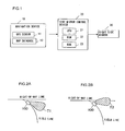
- FIG. 1 shows the structure adopted in the first embodiment of the vehicle situation monitoring apparatus according to the present invention.
- the vehicle situation monitoring apparatus achieved in the first embodiment includes a navigation device 10, a side mirror control device 20, and a right side mirror 30 and adjusts the mirror surface angle of the right side mirror (outside rearview mirror on the right side) 30 by adopting the method to be detailed later.
- the angle of the mirror surface of the right side mirror 30 can be adjusted at least to the left and to the right.
- the navigation device 10 includes at least a GPS sensor 11 and a map database 12. Based upon radio waves originating from a GPS satellite (not shown), the GPS sensor 11 detects the current position of the vehicle. Map data are stored in the map database 12.
- the side mirror control device 20 which includes a CPU 21, a ROM 22,and a RAM 23, controls the mirror surface angle of the right side mirror 30 as explained later.
- FIGS. 2A and 2B illustrate how the side mirror control device 20 controls the right side mirror 30.
- FIGS. 2A and 2B show a vehicle 100 traveling on a yield line about to merge into a right-of-way line.
- FIG. 2A shows a range T1 of the visual field of the right side mirror 30 before the mirror surface angle is adjusted.
- the range of the visual field that can be checked by the driver with the right side mirror 30 normally lies to the rear of the subject vehicle on the right side. For this reason, the driver of the vehicle 100 traveling on the yield line needs to shoulder check for vehicles traveling on the right-of-way line before reaching the merging point.
- FIG. 2B shows a range T2 of the visual field achieved by the vehicle situation monitoring apparatus in the first embodiment by adjusting the mirror surface angle of the right side mirror 30.
- the vehicle situation monitoring apparatus in the first embodiment tilts the mirror surface of the right side mirror 30 toward the right-of-way line, i.e., to the right, when the vehicle 100 traveling on the yield line is about to merge into the right-of-way line.
- the driver of the vehicle 100 is able to check for vehicles traveling on the right-of-way line with the right side mirror 30.
- FIG. 3 shows an example of the start point and the end point for the mirror surface angle adjustment control.
- FIG. 4 shows data indicating the positional coordinates of the control start points, extents of the mirror surface angle adjustment and the positional coordinates of the control end points, which are stored in the ROM 22. These data indicating values determined in advance in correspondence to the positional relationships between individual yield lines and right-of-way lines for a plurality of merging points are stored in advance in the ROM 22.
- the CPU 21 in the side mirror control device 20 adjusts the mirror surface angle of the right side mirror 30 based upon the current position of the subject vehicle detected with the GPS sensor 11 and the data stored in the ROM 22. Namely, as the vehicle traveling on a yield line reaches the control start point at which the mirror surface angle adjustment control is started, the CPU 21 starts to adjust the mirror surface angle of the right side mirror 30 based upon the mirror surface angle stored in the ROM 22 in correspondence to the particular control start point.
- FIG. 5 presents a flowchart of the control executed by the vehicle situation monitoring apparatus in the first embodiment.
- the CPU 21 starts the processing in step S10 as an ignition switch (not shown) is turned on.
- step S10 a decision is made as to whether or not the subject vehicle has reached the control start point based upon the current position of the subject vehicle detected with the GPS sensor 11 and the data indicating the control start point, which are stored in the ROM 22. If it is decided that the subject vehicle has not reached the control start point yet, the operation waits in standby in step S10.
- the CPU 21 judges that a merging point at which the yield line merges with another road is present ahead on the road on which the subject vehicle is currently traveling and, accordingly, the operation proceeds to step S20.
- step S20 the mirror surface angle of the right side mirror 30 is adjusted based upon the mirror surface angle stored in the ROM 22 in correspondence to the specific control start point that the subject vehicle has reached. For instance, if a mirror surface angle of 5° is indicated, the mirror surface of the right side mirror 30 is adjusted by 5° to the right. Once the mirror surface angle is adjusted, the operation proceeds to step S30.
- step S30 a decision is made as to whether or not the subject vehicle has reached the adjustment control end point based upon the current position of the subject vehicle detected with the GPS sensor 11 and the data indicating the control end point stored in the ROM 22. If it is decided that the subject vehicle has not reached the control end point yet, the operation waits in standby in step S30 for the subject vehicle to reach the control end point and once it is decided that the subject vehicle has reached the control end point, the operation proceeds to step S40. In step S40, the mirror surface angle having been adjusted in step S20 is reset, before the mirror surface angle adjustment processing ends.
- the vehicle situation monitoring apparatus in the first embodiment makes a decision as to whether or not a merging point at which the current road merges with another road is present ahead of the road on which the subject vehicle is traveling and adjusts the mirror surface angle of the side mirror before the vehicle reaches the merging point if it is decided that such a merging point is present ahead.
- the mirror surface angle of the side mirror is adjusted when the vehicle traveling on a yield line is about to merge into a right-of-way line, the driver is able to check for any vehicles traveling on the right-of-way line with ease with the side mirror.
- the cost of the entire apparatus can be minimized.
- FIG. 6 shows the structure adopted in the vehicle situation monitoring apparatus in the second embodiment.
- the vehicle situation monitoring apparatus in the second embodiment includes a vehicle speed sensor 40 that detects the speed of the vehicle.
- the vehicle situation monitoring apparatus in the second embodiment selects one of two mirror control start points in correspondence to the current vehicle speed.
- FIG. 7 shows the control start point selected when the vehicle speed is equal to or greater than a predetermined vehicle speed and another control start point that is selected when the vehicle speed is under the predetermined vehicle speed.
- the predetermined vehicle speed is 10 km/h
- x1 indicating the control start point selected when the vehicle speed is equal to or higher than 10 km/h
- x2 indicating the control start point selected when the vehicle speed is lower than 10 km/h.
- the control start point x1 selected when the vehicle speed is equal to or higher than 10 km/h is set further from the merging point than the control start point x2 selected when the vehicle speed is lower than 10 km/h. This ensures that the mirror surface angle adjustment starts earlier when the vehicle speed is high compared to when the vehicle speed is low.
- FIG. 8 shows data indicating control start points x1 selected when the vehicle speed is equal to or higher than 10 km/h, control start points x2 selected when the vehicle speed is lower than 10 km/h, control end points y and extents of surface angle adjustment. Data such as those shown in FIG. 8 are stored in a ROM 22a.
- FIG. 9 presents a flowchart of the control executed by the vehicle situation monitoring apparatus in the second embodiment.
- a CPU 21a of a side mirror control device 20a starts the processing in step S100. It is to be noted that the same step numbers are assigned to steps in the flowchart presented in FIG. 9 in which processing similar to that in the flowchart shown in FIG. 5 is executed, so as to preclude the necessity for a detailed explanation thereof.
- step S100 a decision is made as to whether or not the subject vehicle has reached the control start point x1 based upon the current position of the subject vehicle detected with the GPS sensor 11 and the data indicating the control start point x1, which are stored in the ROM 22a. If it is decided that the subject vehicle has not reached the control start point x1 yet, the operation waits in standby in step S100. If, on the other hand, it is decided that the subject vehicle has reached the control start point x1, it is judged that a merging point at which the current road merges with another road is present ahead on the road on which the subject vehicle is traveling and, accordingly, the operation proceeds to step S110.
- step S110 a decision is made as to whether or not the vehicle speed is equal to or higher than 10 km/h based upon the vehicle speed detected with the vehicle speed sensor 40.
- the operation proceeds to step S20 if the vehicle speed is determined to be equal to or higher than 10 km/h, whereas the operation proceeds to step S120 if the vehicle speed is determined to be lower than 10 km/h.
- step S120 a decision is made as to whether or not the vehicle has reached the control start point x2. If it is decided that the vehicle has not reached the control start point x2 yet, the operation waits in standby in step S120, whereas the operation proceeds to step S20 if the vehicle is determined to have reached the control start point x2.
- step S20 the control for adjusting the mirror surface angle of the right side mirror 30 based upon the mirror surface angle stored in the ROM 22a in correspondence to the control start point x1 or x2 that the vehicle has reached is started. It is to be noted that since the processing executed in steps S20 through S40 is identical to the processing executed in steps S20 through S40 in the flowchart presented in FIG. 5, a detailed explanation is omitted.
- the vehicle situation monitoring apparatus in the second embodiment changes the mirror surface angle adjustment control start position in correspondence to the current speed of the vehicle.
- the mirror surface angle adjustment for the side mirror can be started at the optimal position in correspondence to the vehicle speed. Namely, since the mirror surface angle adjustment is started at a point further away from the merging point when the vehicle is traveling at a higher speed, the driver is able to check for vehicles traveling on the right-of-way line with the adjusted side mirror with a high degree of reliability.
- the vehicle situation monitoring apparatus in the third embodiment determines the position at which the mirror surface angle control is started and the extent of the mirror surface angle adjustment based upon the radius R of the curve in the yield line merging into the right-of-way line. It is to be noted that the vehicle situation monitoring apparatus in the third embodiment adopts a structure identical to the structure of the vehicle situation monitoring apparatus in the first embodiment in FIG. 1. However, since the processing executed by the CPU of the side mirror control device in the third embodiment differs from the processing executed by the CPU 21 of the side mirror control device 20 in the first embodiment, the following explanation is given by using a reference numeral 21b for the CPU.
- FIG. 10A shows a range T3 of the visual field of the right side mirror 30 when the radius R of the curve in the yield line is large
- FIG. 10B shows a range T4 of the visual field of the right side mirror 30 when the radius R of the curve in the yield line is small.
- the mirror surface angle is not adjusted either in FIG. 10A or FIG. 10B. If the curve radius R is large, vehicles traveling on the right-of-way line can be checked with the right side mirror 30 without having to adjust the mirror surface angle, as shown in FIG. 10A. However, if the curve radius R is small, vehicles traveling on the right-of-way line cannot be checked with the right side mirror 30, as shown in FIG. 10B.
- the vehicle situation monitoring apparatus in the third embodiment adjusts the mirror surface angle of the right side mirror 30 in correspondence to the radius R of the curve in the yield line when the subject vehicle traveling on the yield line is merging into the right-of-way line.
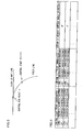
- FIG. 11 shows data indicating the radius R of the curve in the yield line, the position at which the mirror surface angle adjustment is started and the extent of the mirror surface angle adjustment. If the curve radius R is less than 50 m, the mirror surface is turned toward the right-of-way line by 5° when the current vehicle position is 10 m from the merging point. If the curve radius R is equal to or greater than 50 m and equal to or less than 100 m, the mirror surface is turned toward the right-of-way line by 3° when the current vehicle position is 15 m from the merging point. If the curve radius is greater than 100 m, the mirror surface angle is not adjusted.
- the map data stored in the map database 12 of the navigation device 10 are constituted with nodes each indicating an intersection point or a specific point on a road and links each corresponding to a road portion between two nodes.
- the angle ⁇ can be calculated by using the cosine rule based upon the coordinates of the three nodes, and then, based upon the value of ⁇ thus calculated and expression (1) , the curve radius R can be calculated. It is to be noted that the curve radius R is calculated in advance for each yield line merging into a right-of-way line and is stored in the ROM 22.
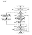
- FIG. 13 presents a flowchart of the control executed by the vehicle situation monitoring apparatus in the third embodiment.
- the CPU 21b starts the processing in step S200.
- step S200 a decision is made as to whether or not the subject vehicle traveling on the yield line has reached a point 100 m from a merging point based upon the current vehicle position detected with the GSS sensor 11 and the map data stored in the map database 12.
- the operation proceeds to step S210 if the vehicle is determined to have reached the point 100 m from the merging point, whereas the operation waits in standby in step S200 if it is decided that the vehicle has not yet reached that point.
- step S210 the data indicating the radius R of the curve in the yield line at the merging point are read from the ROM 22 and a decision is made as to whether or not the curve radius R is less than 50 m.
- the operation proceeds to step S220 if the curve radius R is determined to be less than 50 m, whereas the operation proceeds to step S240 if the curve radius R is determined to be equal to or greater than 50 m.
- step S220 a decision is made as to whether or not the vehicle has reached a point 10 m from the merging point. If it is decided that the vehicle has not yet reached the point 10 m from the merging point, the operation waits in standby in step S220, whereas the operation proceeds to step S230 if the vehicle is determined to have reached the point 10 m from the merging point.
- step S230 the mirror surface of the right side mirror 30 is turned toward the right-of-way line (to the right) by 5° and then the operation proceeds to step S270.
- step S240 a decision is made as to whether or not the radius R read from the ROM 22 in step S210 is equal to or greater than 50 m and equal to or less than 100 m. If the curve radius R is determined to be equal to or greater than 50 m and equal to or less than 100 m, the operation proceeds to step S250. However, if the curve radius is determined to be greater than 100 m, the mirror surface angle adjustment processing ends without adjusting the mirror surface angle.
- step S250 the control for adjusting the mirror surface of the right side mirror 30 at a point 15 m from the merging point, as indicated in FIG. 11 is started. Accordingly, a decision is made in step S250 as to whether or not the vehicle has reached a point 15 m from the merging point. If it is decided that the vehicle has not yet reached the point 15 m from the merging point, the operation waits in standby in step S250, whereas the operation proceeds to step S260 if the vehicle is determined to have reached the point 15 m from the merging point. In step S260, the mirror surface of the right side mirror 30 is turned toward the right-of-way line (to the right) by 3°, before the operation proceeds to step S270.
- step S270 a decision is made as to whether or not the vehicle has reached the merging point.
- the operation waits in standby in step S270 if it is decided that the vehicle has not reached the merging point yet, whereas the operation proceeds to step S280 if the vehicle is determined to have reached the merging point.
- step S280 the mirror surface angle having been adjusted in step S230 or step S260 is reset, and then the mirror surface angle adjustment processing ends.
- the vehicle situation monitoring apparatus in the third embodiment which determines the mirror surface angle adjustment start point and the extent of mirror surface angle adjustment in correspondence to the radius of the curve R in the yield line merging into the right-of-way line, is capable of executing optimal mirror surface angle adjustment control in correspondence to the specific conditions at the merging point. Namely, the mirror surface angle is adjusted to a greater degree and the mirror surface angle adjustment is started at a point closer to the merging point when the radius R of the curve is smaller, and thus, the driver is able to check for any vehicles traveling on the right-of-way line with the side mirror with a high degree of reliability.
- the vehicle situation monitoring apparatus in the third embodiment executes the mirror surface angle adjustment control when the vehicle traveling on a yield line is about to merge into a right-of-way line based upon the radius R of the curve in the yield line.
- the vehicle situation monitoring apparatus in the fourth embodiment executes the mirror surface angle adjustment control by taking into consideration the vehicle speed as well as the radius R of the curve in the yield line. It is to be noted that the structure of the vehicle situation monitoring apparatus in the fourth embodiment is identical to the structure of the vehicle situation monitoring apparatus in FIG. 6 in the second embodiment. However, the processing executed by its CPU is different, and for this reason, the following explanation is given by using reference numeral 21c for the CPU.
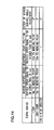
- FIG. 14 shows the relationship among the radius R of the curve in the yield line, the mirror surface angle adjustment start position selected in correspondence to the vehicle speed and the extent of mirror surface angle adjustment.
- the curve radius R is less than 50 m
- the mirror surface angle adjustment processing is started at a point 10 m from the merging point if the vehicle speed is lower than 10 km/h
- the mirror surface angle adjustment processing is started at a point 15 m from the merging point if the vehicle speed is equal to or higher than 10 km/h.
- the mirror surface angle is adjusted by 5° under either set of circumstances.
- the mirror surface angle adjustment processing is started at a point 15 m from the merging point if the vehicle speed is lower than 10 km/h, and the mirror surface angle adjustment processing is started at a point 20 m from the merging point if the vehicle speed is equal to or higher than 10 km/h.
- the mirror surface angle is adjusted by 3° under either set of circumstances. In addition, the mirror surface angle is not adjusted if the curve radius R is greater than 100 m.
- FIG. 15 presents a flowchart of the control executed by the vehicle situation monitoring apparatus in the fourth embodiment.
- the same step numbers are assigned to steps in the flowchart in FIG. 15 in which processing identical to that in the flowchart in FIG. 13 is executed to preclude the need for a detailed explanation thereof.
- the CPU 21c starts the processing in step S200 as the ignition switch (not shown) is turned on.
- step S200 a decision is made as to whether or not the vehicle has reached a point 100 m from the merging point.
- the operation proceeds to step S210 if the vehicle is determined to have reached the point 100 m from the merging point, whereas the operation waits in standby in step S200 if it is decided that the vehicle has not yet reached the point.
- step S210 a decision is made as to whether or not the radius R of the curve in the yield line is less than 50 m.
- the operation proceeds to step S300 if the curve radius R is determined to be less than 50 m, whereas the operation proceeds to step S240 if it is determined to be equal to or greater than 50 m.
- step S300 a decision is made as to whether or not the vehicle speed detected with the vehicle speed sensor 40 is equal to or higher than 10 km/h.
- the operation proceeds to step S320 if the vehicle speed is determined to be equal to or higher than 10 km/h, whereas the operation proceeds to step S310 if the vehicle speed is determined to be lower than 10 km/h.
- step S310 a decision is made as to whether or not the vehicle has reached a point 10 m from the merging point. If it is decided that the vehicle has not reached the point 10 m from the merging point yet, the operation waits in standby in step S310 whereas the operation proceeds to step S230 if the vehicle is determined to have reached the point 10 m from the merging point.
- step S320 a decision is made as to whether or not the vehicle has reached a point 15 m from the merging point.
- the operation waits in standby in step S320 if it is decided that the vehicle has not reached a point 15 m from the merging point yet, whereas the operation proceeds to step S230 if the vehicle is judged to have reached a point 15 m from the merging point.
- step S230 the mirror surface of the right side mirror 30 is turned toward the right-of-way line (to the right) by 5°, and then the operation proceeds to step S270.
- step S240 a decision is made as to whether or not the curve radius R is equal to or greater than 50 m and equal to or less than 100 m.
- the operation proceeds to step S330 if the curve radius R is determined to be equal to or greater than 50 m and equal to or less than 100 m, whereas the mirror surface angle adjustment processing ends without adjusting the mirror surface angle if the curve radius R is determined to be greater than 100 m.
- step S330 a decision is made as to whether or not the vehicle speed detected with the vehicle speed sensor 40 is equal to or higher than 10 km/h.
- the operation proceeds to step S340 if the vehicle speed is determined to be equal to or higher than 10 km/h, whereas the operation proceeds to step S350 if the vehicle speed is judged to be lower than 10 km/h.
- step S340 a decision is made as to whether or not the vehicle has reached a point 15 m from the merging point.
- the operation waits in standby in step S340 if it is decided that the vehicle has not reached a point 15 m from the merging point yet, whereas the operation proceeds to step S260 if the vehicle is judged to have reached a point 15 m from the merging point.
- step S350 a decision is made as to whether or not the vehicle has reached a point 20 m from the merging point.
- step S350 waits in standby in step S350 if it is decided that the vehicle has not reached a point 20 m from the merging point yet, whereas the operation proceeds to step S260 if the vehicle is judged to have reached a point 20 m from the merging point.
- step S260 the mirror surface of the right side mirror 30 is turned toward the right-of-way line (to the right) by 3°, and then the operation proceeds to in step S270. Since the processing executed in steps S270 and S280 is identical to the processing executed in steps S270 and S280 in the flowchart presented in FIG. 13, a detailed explanation is not provided.
- the vehicle situation monitoring apparatus in the fourth embodiment which determines the mirror surface angle adjustment start position and the extent of the mirror surface angle adjustment based upon the radius of the curve in the yield line and the current vehicle speed, is capable of executing even better mirror surface angle adjustment control when the vehicle traveling on a yield line merges into a right-of-way line.
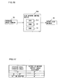
- FIG. 16 shows the structure adopted in the fifth embodiment of the vehicle situation monitoring apparatus.
- the vehicle situation monitoring apparatus in the fifth embodiment includes a side mirror control device 20d and a steering angle sensor 50.
- the steering angle sensor 50 detects the steering angle at the steering wheel.
- FIG. 17 shows the relationship between the steering angle and the extent of the mirror surface angle adjustment at the right side mirror 30.
- the mirror surface angle of the right side mirror 30 is adjusted a 5°, whereas the mirror surface angle is not adjusted at all if the steering wheel steering angle is less than 5° or greater than 10°. Namely, if the steering angle is equal to or greater than 5° and equal to or less than 10°, it is judged that the vehicle traveling on a yield line is about to merge into a right-of-way line and, accordingly, the mirror surface angle is adjusted.
- the steering angle is greater than 10°, it is judged that the vehicle is being parked or the like, and accordingly, the mirror surface angle is not adjusted.
- the steering angle is less than 5°, it is judged that the driver of the subject vehicle merging into a right-of-way line can check for any vehicle traveling on the right-of-way line with the side mirror without adjusting the mirror surface angle and thus, the mirror surface angle is not adjusted.
- FIG. 18 presents a flowchart of the control executed by the vehicle situation monitoring apparatus in the fifth embodiment.
- the processing in step S400 is started by a CPU 21d of the side mirror control device 20d as the ignition switch (not shown) is turned on.
- step S400 a decision is made as to whether or not the steering angle detected with the steering angle sensor 50 is equal to or greater than 5° and equal to or less than 10°.
- the operation proceeds to step S410 if the steering angle is determined to be equal to or greater than 5° and equal to or less than 10°, otherwise the operation proceeds to step S420.
- step S410 the mirror surface of the right side mirror 30 is turned toward the right-of-way line (to the right) by 5°, before the operation returns to step S400.
- step S420 the extent of the mirror surface angle adjustment is set to 0° for the right side mirror 30. Namely, if the mirror surface angle has been adjusted in step S410, the mirror surface angle is reset to the initial pre-adjustment setting in step S420, whereas if the mirror surface angle has not been adjusted, the initial mirror surface angle remains unchanged in step S420.
- the vehicle situation monitoring apparatus in the fifth embodiment makes a decision as to whether or not the vehicle is about to merge into a right-of-way line based on the steering angle of the steering wheel and adjusts the mirror surface angle of the side mirror if it is decided that the vehicle is about to merge into a right-of-way line.
- mirror surface angle adjustment control is achieved by adopting a simple structure.
- the mirror surface angle of a side mirror of the subject vehicle is adjusted as the vehicle traveling on a yield line approaches a merging point. If the vehicle is equipped with a system that includes an on-vehicle camera capable of photographing the area surrounding the vehicle, the on-vehicle camera may be turned toward the right-of-way line as the vehicle traveling on the yield line approaches the merging point.
- FIG. 19 shows the structure of a vehicle situation monitoring apparatus equipped with an on-vehicle camera 60. This vehicle situation monitoring apparatus enables the driver to check the image obtained with the on-vehicle camera 60 on a monitor 70 installed in the vehicle.
- an on-vehicle camera 60 may be similarly mounted and control may be executed to set the direction along which an image is photographed with the on-vehicle camera 60 toward the right-of-way line as the vehicle traveling on the yield line approaches the merging point.
- the mirror surface angle is adjusted when the vehicle traveling on a yield line approaches a merging point and the mirror surface angle is reset to the pre-adjustment state when the vehicle reaches the control end point or the merging point.
- the mirror surface angle may be controlled so that the extent of the mirror surface angle adjustment is gradually reset to 0° until the vehicle travels to the control end point.
- the vehicle situation monitoring apparatus in the third embodiment determines the mirror surface angle adjustment start position and the extent of the mirror surface angle adjustment based upon the radius R of the curve in the yield line merging into the right-of-way line
- the mirror surface angle adjustment start position and the extent of the mirror surface angle adjustment may instead be determined based upon the steering angle at the steering wheel.
- the mirror surface angle of the right side mirror is turned to the right in the explanation given in reference to the embodiments. If, on the other hand, the vehicle is merging into the right-of-way line from the right side, the mirror surface angle of a left side mirror may be turned to the left. In addition, the mirror surface angle of a mirror other than a side mirror, e.g. , the mirror surface angle of a rearview mirror in the cabin, may be adjusted instead.
- the position of the subject vehicle may be detected through self-contained navigation executed by using a gyro sensor (not shown) and the vehicle speed sensor, instead of satellite navigation.
- the proximity of the subject vehicle to the merging point may be detected by mounting a camera at the vehicle and executing white line recognition processing on the image captured with the on-vehicle camera.
- the mirror surface angle adjustment start position and the extent of angle adjustment may be custom set for each driver.
- While the vehicle situation monitoring apparatus in the fifth embodiment adjusts the mirror surface angle of the side mirror in correspondence to the steering angle at the steering wheel, a decision may be made as to whether or not a merging point is present ahead on the road on which the subject vehicle is currently traveling and the mirror surface angle may be adjusted if it is decided that a merging point is present ahead and the steering angle at the steering wheel is within a predetermined range.
Landscapes
- Engineering & Computer Science (AREA)
- Radar, Positioning & Navigation (AREA)
- Remote Sensing (AREA)
- Automation & Control Theory (AREA)
- Physics & Mathematics (AREA)
- General Physics & Mathematics (AREA)
- Traffic Control Systems (AREA)
- Rear-View Mirror Devices That Are Mounted On The Exterior Of The Vehicle (AREA)
Claims (19)
- Vorrichtung zur Überwachung der Lage eines Fahrzeugs, die Folgendes umfasst:Knotenpunkt-Entscheidungsmittel (10, 20) zum Treffen einer Entscheidung in Bezug darauf, ob ein Knotenpunkt einer Straße, auf der ein gegenständliches Fahrzeug fährt, und einer weiteren Straße weiter vom auf der Straße, auf der das gegenständliche Fahrzeug fährt, vorhanden ist; undSteuermittel (20) zum Einstellen des Winkels eines Fahrzeuglagekontrollmittels (30, 60), mit dem der Fahrer die Verkehrslage optisch kontrollieren kann, wenn das Knotenpunkt-Entscheidungsmittel (10, 20) ermittelt, dass ein Knotenpunkt vorhanden ist.
- Vorrichtung zur Überwachung der Lage eines Fahrzeugs nach Anspruch 1, die ferner Folgendes umfasst:Entscheidungsmittel für die Fahrt auf Vorfahrt-gewähren-Strecken (10, 20) zum Treffen einer Entscheidung in Bezug darauf, ob das Fahrzeug auf einer Vorfahrt-gewähren-Strecke fährt, die in eine Vorfahrtsstrecke einmündet, die eine Vorfahrtsstraße ist, wobei:wenn das Knotenpunkt-Entscheidungsmittel (10, 20) ermittelt, dass ein Knotenpunkt vorhanden ist, und das Entscheidungsmittel für die Fahrt auf Vorfahrt-gewähren-Strecken (10, 20) ermittelt, dass das Fahrzeug auf einer Vorfahrt-gewähren-Strecke fährt, steuert das Steuermittel (20) den Winkel des Fahrzeuglagekontrollmittels (30; 60), um den Fahrer zu befähigen zu kontrollieren, ob auf der Vorfahrtsstrecke fahrende Objekte fahren.
- Vorrichtung zur Überwachung der Lage eines Fahrzeugs nach Anspruch 1, die ferner Folgendes umfasst:Positionserkennungsmittel (11) zum Erkennen einer aktuellen Position des Fahrzeugs; undSteuerungsanfangspositionsspeichermittel (22) zum Speichern einer Mehrzahl von Steuerungsanfangspositionen entsprechend jedem Knotenpunkt; wobei:wenn die vom Positionserkennungsmittel (11) erkannte Fahrzeugposition und eine im Steuerungsanfangspositionsspeichermittel (22) gespeicherte Steuerungsanfangsposition miteinander übereinstimmen, beginnt das Steuermittel (20) die Steuerung des Winkels des Fahrzeuglagekontrollmittels (30; 60) zu implementieren.
- Vorrichtung zur Überwachung der Lage eines Fahrzeugs nach Anspruch 1, die ferner Folgendes umfasst:Positionserkennungsmittel (11) zum Erkennen einer aktuellen Position des Fahrzeugs; undSteuerungsendepositionsspeichermittel (22) zum Speichern einer Mehrzahl von Steuerungsendepositionen entsprechend jedem Knotenpunkt; wobei:wenn die vom Positionserkennungsmittel (11) erkannte Fahrzeugposition und eine im Steuerungsendepositionsspeichermittel (22) gespeicherte Steuerungsendeposition miteinander übereinstimmen, beginnt das Steuermittel (20) die Steuerung für das Rücksetzen des Winkels des Fahrzeuglagekontrollmittels (30; 60) auf einen Ausgangswinkel vor Steuerungsanfang zu implementieren.
- Vorrichtung zur Überwachung der Lage eines Fahrzeugs nach Anspruch 1, die ferner Folgendes umfasst:Positionserkennungsmittel (11) zum Erkennen einer aktuellen Position des Fahrzeugs; undWinkeleinstellungsspeichermittel (22) zum Speichern einer Mehrzahl von Datensätzen, die Winkel des Fahrzeuglagekontrollmittels (30; 60) entsprechend jedem Knotenpunkt anzeigen; wobeidas Steuermittel (20) den Winkel des Fahrzeuglagekontrollmittels (30; 60) auf der Basis der vom Fahrzeugpositionserkennungsmittel (11) erkannten Fahrzeugposition und der Mehrzahl von im Winkeleinstellungsspeichermittel (22) gespeicherten Datensätzen einstellt.
- Vorrichtung zur Überwachung der Lage eines Fahrzeugs nach Anspruch 1, die ferner Folgendes umfasst:Fahrzeuggeschwindigkeitserkennungsmittel (40) zum Erkennen der Geschwindigkeit des Fahrzeugs; wobeidas Steuermittel (20) die Steuerung zum Einstellen des Winkels des Fahrzeuglagekontrollmittels (30; 60) an einer vom Knotenpunkt weiter entfernten Position beginnt, wenn die vom Fahrzeuggeschwindigkeitserkennungsmittel (40) erkannte Fahrzeuggeschwindigkeit höher ist.
- Vorrichtung zur Überwachung der Lage eines Fahrzeugs nach Anspruch 1, bei der
das Steuermittel (20) den Winkel des Fahrzeuglagekontrollmittels (30; 60) auf der Basis eines Radius einer Kurve in der Straße, auf der das gegenständliche Fahrzeug fährt, ermittelt. - Vorrichtung zur Überwachung der Lage eines Fahrzeugs nach Anspruch 7, bei der
das Steuermittel (20) den Winkel des Fahrzeuglagekontrollmittels (30; 60) in einem größeren Maße verstellt, wenn der Radius der Kurve in der Straße, auf der das gegenständliche Fahrzeug fährt, kleiner ist. - Vorrichtung zur Überwachung der Lage eines Fahrzeugs nach Anspruch 7, bei der
das Steuermittel (20) den Winkel des Fahrzeuglagekontrollmittels (30; 60) nicht verstellt, wenn der Radius der Kurve in der Straße, auf der das gegenständliche Fahrzeug fährt, gleich einem vorbestimmten Wert oder größer als dieser ist. - Vorrichtung zur Überwachung der Lage eines Fahrzeugs nach Anspruch 1, bei der
das Steuermittel (20) eine Steuerungsanfangsposition ermittelt, an der das Steuermittel (20) die Steuerung zum Einstellen des Winkels des Fahrzeuglagekontrollmittels (30; 60) auf der Basis eines Radius einer Kurve in der Straße, auf der das gegenständliche Fahrzeug fährt, beginnt. - Vorrichtung zur Überwachung der Lage eines Fahrzeugs nach Anspruch 1, bei der
das Steuermittel (20) beginnt, die Steuerung zum Einstellen des Winkels des Fahrzeuglagekontrollmittels (30; 60) an einer Position näher am Knotenpunkt beginnt, wenn der Radius der Kurve in der Straße, auf der das gegenständliche Fahrzeug fährt, kleiner ist. - Vorrichtung zur Überwachung der Lage eines Fahrzeugs nach Anspruch 1, die ferner Folgendes umfasst:ein Fahrzeuggeschwindigkeitserkennungsmittel (40) zum Erkennen der Geschwindigkeit des Fahrzeugs, wobeidas Steuermittel (20) den Winkel des Fahrzeuglagekontrollmittels (30; 60) auf der Basis eines Radius einer Kurve der Straße, auf der das gegenständliche Fahrzeug fährt, und der vom Fahrzeuggeschwindigkeitserkennungsmittel (40) erkannten Fahrzeuggeschwindigkeit ermittelt.
- Vorrichtung zur Überwachung der Lage eines Fahrzeugs nach Anspruch 1, die ferner Folgendes umfasst:ein Fahrzeuggeschwindigkeitserkennungsmittel (40) zum Erkennen der Geschwindigkeit des Fahrzeugs, wobeidas Steuermittel (20) eine Steuerungsanfangsposition ermittelt, an der das Steuermittel (20) die Steuerung zum Einstellen des Winkels des Fahrzeuglagekontrollmittels (30; 60) auf der Basis eines Radius einer Kurve der Straße, auf der das gegenständliche Fahrzeug fährt, und der vom Fahrzeuggeschwindigkeitserkennungsmittel (40) erkannten Fahrzeuggeschwindigkeit beginnt.
- Vorrichtung zur Überwachung der Lage eines Fahrzeugs nach Anspruch 1, die ferner Folgendes umfasst:Lenkwinkelerkennungsmittel (50) zum Erkennen eines Lenkradlenkwinkels; wobei
das Steuermittel (20) den Winkel des Fahrzeuglagekontrollmittels (30; 60) auf der Basis des vom Lenkwinkelerkennungsmittel (50) erkannten Lenkwinkels ermittelt. - Vorrichtung zur Überwachung der Lage eines Fahrzeugs nach Anspruch 1, die ferner Folgendes umfasst:Lenkwinkelerkennungsmittel (50) zum Erkennen eines Lenkradlenkwinkels; wobeidas Steuermittel (20) eine Steuerungsanfangsposition ermittelt, an der das Steuermittel (20) die Steuerung zum Einstellen des Winkels des Fahrzeuglagekontrollmittels (30; 60) auf der Basis des vom Lenkwinkelerkennungsmittel (50) erkannten Lenkwinkels beginnt.
- Vorrichtung zur Überwachung der Lage eines Fahrzeugs nach Anspruch 1, die ferner Folgendes umfasst:Lenkwinkelerkennungsmittel (50) zum Erkennen eines Lenkradlenkwinkels; wobei
das Knotenpunkt-Entscheidungsmittel (10, 20) ermittelt, dass weiter vom auf der Straße, auf der das gegenständliche Fahrzeug fährt, ein Knotenpunkt vorhanden ist, wenn der vom Lenkwinkelerkennungsmittel (50) erkannte Lenkwinkel innerhalb eines vorbestimmten Winkelbereichs liegt. - Vorrichtung zur Überwachung der Lage eines Fahrzeugs nach Anspruch 1, bei der
das Fahrzeuglagekontrollmittel von einer Spiegeloberfläche eines Außenspiegels (30) gebildet wird. - Vorrichtung zur Überwachung der Lage eines Fahrzeugs nach Anspruch 1, bei der
das Fahrzeuglagekontrollmittel ein Bilderfassungsmittel (60) zum Erfassen eines Bildes in einem das Fahrzeug umgebenden Bereich ist;
die Vorrichtung zur Überwachung der Lage eines Fahrzeugs ferner ein Anzeigemittel (70) zum Anzeigen des vom Bilderfassungsmittel (60) erfassten Bildes aufweist und
das Steuermittel (20), wenn das Knotenpunkt-Entscheidungsmittel (10, 20) ermittelt, dass ein Knotenpunkt vorhanden ist, eine Bilderfassungsrichtung einstellt, an der entlang das Bilderfassungsmittel (60) das Bild in Richtung auf die andere Straße, die am Knotenpunkt einmündet, erfasst. - Verfahren zur Überwachung der Lage eines Fahrzeugs, das Folgendes umfasst:Treffen einer Entscheidung in Bezug darauf, ob ein Knotenpunkt einer Straße, auf der ein gegenständliches Fahrzeug fährt, und einer weiteren Straße weiter vom auf der Straße, auf der das gegenständliche Fahrzeug fährt, vorhanden ist oder nicht; undEinstellen des Winkels des Fahrzeuglagekontrollmittels (30; 60), mit dem der Fahrer die Verkehrslage optisch kontrollieren kann, wenn ermittelt wurde, dass ein Knotenpunkt vorhanden ist.
Applications Claiming Priority (2)
| Application Number | Priority Date | Filing Date | Title |
|---|---|---|---|
| JP2004009248 | 2004-01-16 | ||
| JP2004009248A JP2005199910A (ja) | 2004-01-16 | 2004-01-16 | 車両用ミラー制御装置および車両用ミラー制御方法 |
Publications (2)
| Publication Number | Publication Date |
|---|---|
| EP1555159A1 EP1555159A1 (de) | 2005-07-20 |
| EP1555159B1 true EP1555159B1 (de) | 2006-12-27 |
Family
ID=34616910
Family Applications (1)
| Application Number | Title | Priority Date | Filing Date |
|---|---|---|---|
| EP05250001A Expired - Lifetime EP1555159B1 (de) | 2004-01-16 | 2005-01-04 | Vorrichtung und Verfahren zur Überwachung des Zustands eines Fahrzeugs |
Country Status (5)
| Country | Link |
|---|---|
| US (1) | US20050159862A1 (de) |
| EP (1) | EP1555159B1 (de) |
| JP (1) | JP2005199910A (de) |
| CN (1) | CN1319776C (de) |
| DE (1) | DE602005000360T2 (de) |
Families Citing this family (13)
| Publication number | Priority date | Publication date | Assignee | Title |
|---|---|---|---|---|
| JP4720383B2 (ja) * | 2005-09-01 | 2011-07-13 | トヨタ自動車株式会社 | 車両制御装置 |
| EP2246762B1 (de) * | 2009-04-27 | 2012-06-06 | Magneti Marelli S.p.A. | System und Verfahren zur Fahrerunterstützung an Straßenkreuzungen |
| KR101738026B1 (ko) * | 2011-10-11 | 2017-05-22 | 현대자동차주식회사 | 주행중인 차량의 사각지대 감소를 위한 사이드미러 제어 시스템 및 그 방법 |
| US20130342926A1 (en) * | 2012-06-22 | 2013-12-26 | Markus Lutz | Method And System For Dynamically Adjusting A Vehicle Mirror |
| KR101481229B1 (ko) | 2012-10-23 | 2015-01-09 | 현대자동차주식회사 | 사이드미러 조절방법 및 조절시스템 |
| US9026300B2 (en) | 2012-11-06 | 2015-05-05 | Google Inc. | Methods and systems to aid autonomous vehicles driving through a lane merge |
| CN102968902A (zh) * | 2012-12-11 | 2013-03-13 | 苏州群凯信息系统有限公司 | 一种载运工具视频监控与录像系统 |
| CN105015423B (zh) * | 2015-07-20 | 2017-09-26 | 北京汽车股份有限公司 | 后视镜控制方法、后视镜控制系统及汽车 |
| WO2017154213A1 (ja) * | 2016-03-11 | 2017-09-14 | 三菱電機株式会社 | 車載装置、警報出力方法及び警報出力プログラム |
| CN106767803A (zh) * | 2016-12-16 | 2017-05-31 | 杭州奥腾电子股份有限公司 | 利用陀螺仪调整摄像头避免道路目标漏检的方法及其装置 |
| CN115635914A (zh) * | 2021-07-19 | 2023-01-24 | 上汽通用汽车有限公司 | 外后视镜控制设备、方法、车辆和存储介质 |
| JP7737276B2 (ja) * | 2021-09-29 | 2025-09-10 | 株式会社Subaru | ミラー位置登録制御装置 |
| US20260109293A1 (en) | 2024-10-23 | 2026-04-23 | GM Global Technology Operations LLC | Smart vehicle systems and control logic with automated lane merging assistance |
Family Cites Families (7)
| Publication number | Priority date | Publication date | Assignee | Title |
|---|---|---|---|---|
| ATE189878T1 (de) * | 1994-11-25 | 2000-03-15 | Bertil A Brandin | Verfahren und vorrichtung zum automatischen einstellen von rückspiegeln |
| JPH08263793A (ja) * | 1995-03-23 | 1996-10-11 | Honda Motor Co Ltd | 車両制御装置 |
| US5798575A (en) * | 1996-07-11 | 1998-08-25 | Donnelly Corporation | Vehicle mirror digital network and dynamically interactive mirror system |
| DE10016222A1 (de) * | 2000-03-31 | 2001-10-31 | Volkswagen Ag | Verfahren und Einrichtung zur elektrichen Verstellung der Außenspiegel bei Kraftfahrzeugen |
| US6672728B1 (en) * | 2001-09-04 | 2004-01-06 | Exon Science Inc. | Exterior rearview mirror with automatically adjusted view angle |
| EP1327560A3 (de) * | 2002-01-15 | 2003-11-26 | Exon Science Inc. | Steuergerät und -methode zur automatischen Anpassung des Sichtwinkels eines Rückspiegels gemäss der Ausgabe eines Navigationssystems |
| JP2003333586A (ja) * | 2002-05-17 | 2003-11-21 | Pioneer Electronic Corp | 撮像装置、撮像装置の制御方法 |
-
2004
- 2004-01-16 JP JP2004009248A patent/JP2005199910A/ja not_active Abandoned
-
2005
- 2005-01-04 EP EP05250001A patent/EP1555159B1/de not_active Expired - Lifetime
- 2005-01-04 DE DE602005000360T patent/DE602005000360T2/de not_active Expired - Fee Related
- 2005-01-05 US US11/028,606 patent/US20050159862A1/en not_active Abandoned
- 2005-01-14 CN CNB2005100045107A patent/CN1319776C/zh not_active Expired - Fee Related
Also Published As
| Publication number | Publication date |
|---|---|
| CN1319776C (zh) | 2007-06-06 |
| DE602005000360T2 (de) | 2007-10-18 |
| EP1555159A1 (de) | 2005-07-20 |
| JP2005199910A (ja) | 2005-07-28 |
| DE602005000360D1 (de) | 2007-02-08 |
| CN1641713A (zh) | 2005-07-20 |
| US20050159862A1 (en) | 2005-07-21 |
Similar Documents
| Publication | Publication Date | Title |
|---|---|---|
| CN113246993B (zh) | 驾驶支援系统 | |
| EP3045997B1 (de) | Alarmvorrichtung und alarmverfahren | |
| EP3357793B1 (de) | Parkhilfevorrichtung | |
| EP2990265B1 (de) | Fahrzeugsteuerungsvorrichtung | |
| US11498588B2 (en) | Vehicle control apparatus | |
| US20130049988A1 (en) | Device and method for traffic sign recognition | |
| CN112703540B (zh) | 驾驶辅助方法和驾驶辅助装置 | |
| EP3838701B1 (de) | Fahrzeugfahrtsteuerungsverfahren und fahrtsteuerungsvorrichtung | |
| EP1555159B1 (de) | Vorrichtung und Verfahren zur Überwachung des Zustands eines Fahrzeugs | |
| US11256928B2 (en) | Information providing apparatus and methods for a vehicle | |
| US11900698B2 (en) | Information processing device and information processing method | |
| WO2013051306A1 (ja) | 脇見検出装置 | |
| JP7593806B2 (ja) | 車両操作システム、車両制御装置、車両操作方法及び車両操作プログラム | |
| JP2004310522A (ja) | 車両用画像処理装置 | |
| JP2013109505A (ja) | 周辺監視装置 | |
| JP7066463B2 (ja) | 走行支援システムおよび車両の制御方法 | |
| US12384376B2 (en) | Vehicle system, control method, and storage medium | |
| JP7069726B2 (ja) | 通知装置及び車載機 | |
| JP4066869B2 (ja) | 車両用画像処理装置 | |
| CN115195599A (zh) | 控制装置、控制装置的动作方法以及存储介质 | |
| KR20190061137A (ko) | 가상차선 유지 장치 및 그 방법 | |
| US20230242108A1 (en) | Vehicle control apparatus | |
| JP2021039690A (ja) | 車両運転支援方法及び車両運転支援システム | |
| JP2007102578A (ja) | 距離算出装置及び距離算出方法並びにその装置を有する車両 | |
| JP4706362B2 (ja) | 車両用ナビゲーションシステム |
Legal Events
| Date | Code | Title | Description |
|---|---|---|---|
| PUAI | Public reference made under article 153(3) epc to a published international application that has entered the european phase |
Free format text: ORIGINAL CODE: 0009012 |
|
| 17P | Request for examination filed |
Effective date: 20050126 |
|
| AK | Designated contracting states |
Kind code of ref document: A1 Designated state(s): AT BE BG CH CY CZ DE DK EE ES FI FR GB GR HU IE IS IT LI LT LU MC NL PL PT RO SE SI SK TR |
|
| AX | Request for extension of the european patent |
Extension state: AL BA HR LV MK YU |
|
| AKX | Designation fees paid |
Designated state(s): DE FR GB |
|
| GRAP | Despatch of communication of intention to grant a patent |
Free format text: ORIGINAL CODE: EPIDOSNIGR1 |
|
| GRAS | Grant fee paid |
Free format text: ORIGINAL CODE: EPIDOSNIGR3 |
|
| GRAA | (expected) grant |
Free format text: ORIGINAL CODE: 0009210 |
|
| AK | Designated contracting states |
Kind code of ref document: B1 Designated state(s): DE FR GB |
|
| REG | Reference to a national code |
Ref country code: GB Ref legal event code: FG4D |
|
| REF | Corresponds to: |
Ref document number: 602005000360 Country of ref document: DE Date of ref document: 20070208 Kind code of ref document: P |
|
| ET | Fr: translation filed | ||
| PLBE | No opposition filed within time limit |
Free format text: ORIGINAL CODE: 0009261 |
|
| STAA | Information on the status of an ep patent application or granted ep patent |
Free format text: STATUS: NO OPPOSITION FILED WITHIN TIME LIMIT |
|
| 26N | No opposition filed |
Effective date: 20070928 |
|
| PGFP | Annual fee paid to national office [announced via postgrant information from national office to epo] |
Ref country code: DE Payment date: 20071231 Year of fee payment: 4 |
|
| PGFP | Annual fee paid to national office [announced via postgrant information from national office to epo] |
Ref country code: FR Payment date: 20080108 Year of fee payment: 4 |
|
| GBPC | Gb: european patent ceased through non-payment of renewal fee |
Effective date: 20090104 |
|
| PG25 | Lapsed in a contracting state [announced via postgrant information from national office to epo] |
Ref country code: DE Free format text: LAPSE BECAUSE OF NON-PAYMENT OF DUE FEES Effective date: 20090801 |
|
| REG | Reference to a national code |
Ref country code: FR Ref legal event code: ST Effective date: 20091030 |
|
| PG25 | Lapsed in a contracting state [announced via postgrant information from national office to epo] |
Ref country code: GB Free format text: LAPSE BECAUSE OF NON-PAYMENT OF DUE FEES Effective date: 20090104 |
|
| PG25 | Lapsed in a contracting state [announced via postgrant information from national office to epo] |
Ref country code: FR Free format text: LAPSE BECAUSE OF NON-PAYMENT OF DUE FEES Effective date: 20090202 |