EP1553600A2 - Lecteur de disque - Google Patents
Lecteur de disque Download PDFInfo
- Publication number
- EP1553600A2 EP1553600A2 EP05000077A EP05000077A EP1553600A2 EP 1553600 A2 EP1553600 A2 EP 1553600A2 EP 05000077 A EP05000077 A EP 05000077A EP 05000077 A EP05000077 A EP 05000077A EP 1553600 A2 EP1553600 A2 EP 1553600A2
- Authority
- EP
- European Patent Office
- Prior art keywords
- deck
- guide rail
- disk
- vibration damping
- guide shaft
- Prior art date
- Legal status (The legal status is an assumption and is not a legal conclusion. Google has not performed a legal analysis and makes no representation as to the accuracy of the status listed.)
- Granted
Links
Images


Classifications
-
- G—PHYSICS
- G11—INFORMATION STORAGE
- G11B—INFORMATION STORAGE BASED ON RELATIVE MOVEMENT BETWEEN RECORD CARRIER AND TRANSDUCER
- G11B33/00—Constructional parts, details or accessories not provided for in the other groups of this subclass
- G11B33/02—Cabinets; Cases; Stands; Disposition of apparatus therein or thereon
- G11B33/08—Insulation or absorption of undesired vibrations or sounds
-
- G—PHYSICS
- G11—INFORMATION STORAGE
- G11B—INFORMATION STORAGE BASED ON RELATIVE MOVEMENT BETWEEN RECORD CARRIER AND TRANSDUCER
- G11B7/00—Recording or reproducing by optical means, e.g. recording using a thermal beam of optical radiation by modifying optical properties or the physical structure, reproducing using an optical beam at lower power by sensing optical properties; Record carriers therefor
- G11B7/08—Disposition or mounting of heads or light sources relatively to record carriers
- G11B7/085—Disposition or mounting of heads or light sources relatively to record carriers with provision for moving the light beam into, or out of, its operative position or across tracks, otherwise than during the transducing operation, e.g. for adjustment or preliminary positioning or track change or selection
- G11B7/0857—Arrangements for mechanically moving the whole head
- G11B7/08582—Sled-type positioners
Definitions
- the present invention relates to a disk player for effecting the reproduction, recording, or deleting of an optical disk or a magnetic disk (hereafter referred to as the disk) such as a DVD.
- a synthetic resin-made drive chassis 2 is disposed in a housing 1 in such a manner as to be movable in upward and downward directions a and b by means of a pair of pivot shafts 2a respectively provided projectingly on rear portions of both side surfaces thereof.
- a cam shaft 2b provided projectingly on a front surface of the drive chassis 2 is fitted in a cam hole 3a of a cam plate 3 which is movable in leftward and rightward directions c and d .
- a deck 2A is integrally formed on a front side of the drive chassis 2, while an accommodating recess 2B is formed on a side located rearwardly of the deck 2A of the drive chassis 2.
- One side edge of the accommodating recess 2B is formed as a guide rail 4 extending in backward and forward directions e and f from a rear end portion of the drive chassis 2 to the deck 2A.
- a front end 5a of a guide shaft 5 is fitted in a fixing hole 6 of the deck 2A, and a rear end 5b of the guide shaft 5 is fixed to the rear end portion of the drive chassis 2 by means of a screw 7, the guide shaft 5 is disposed on the other side edge side of the accommodating recess 2B in parallel with the guide rail 4.
- an optical pick up 9 made up of a synthetic resin-made base 9A and a pickup body 9B disposed on the base 9A is disposed in the accommodating recess 2B.
- the pickup body 9B includes an actuator base 10 screwed down onto the base 9A; a lens holder 12 having an objective lens OL and fitted in a supporting shaft 11 provided uprightly on a bottom plate of the actuator base 10; a focusing coil 13 and a tracking coil 14 installed on the lens holder 12; and a pair of permanent magnets 15 opposing each other with the lens holder 12 interposed therebetween.
- the lens holder 12 As the lens holder 12 is moved in focusing directions g and h by exciting the focusing coil 13 at a predetermined input frequency, and the tracking coil 14 is exited at a predetermined input frequency, the lens holder 12 is moved in tracking directions i and j .
- a pair of outwardly expanding and inclined inner side surfaces 18a of an annular guide groove 18, which is formed in an outer peripheral surface of a guide roller 17 pivotally secured to one end portion of the base 9A, are engaged with the guide rail 4.
- the guide shaft 5 is fitted in a bearing hole 19a of each of a front and rear pair of bearing portions integrally provided projectingly on the other end portion of the base 9A.
- Apinion 21 is threadedly engaged with a rack 20 connected to the other end portion of the base 9A.
- the optical pick up 9 is reciprocatingly moved in the backward and forward directions e and f along the guide rail 4 and the guide shaft 5 by means of the rack 20.
- a recessed groove 25 communicating with the accommodating recess 2B is formed in the center of a rear portion of the deck 2A.
- a spindle motor 26 is fixed in the recessed groove 25, and a turntable 27 for mounting a disk D is secured on a rotating shaft 26a of the spindle motor 26.
- the drive chassis 2 is moved in the upward directions a about the pivot shaft 2a by means of the cam hole 3a and the cam shaft 2b so as to be set in a horizontal state, the disk D is thereby mounted on the turntable 27 (Fig. 7).
- the disk D is rotated at high speed by the spindle motor 26, and the optical pick up 9 is reciprocatingly moved in the backward and forward directions e and f along the guide rail 4 and the guide shaft 5.
- the lens holder 12 is moved in the focusing directions g and h and the tracking directions i and j by exciting the focusing coil 13 and the tracking coil 14 at the predetermined input frequencies. Further, as laser light is projected onto the disk D through the objective lens OL, information recorded on the disk D is read.
- the one side edge of the accommodating recess 2B formed in the drive chassis 2 is used jointly as the guide rail 4 to attain a cost reduction, and there is an advantage in that as compared with a case where two guide shafts 5 are used, the number of parts is small, so that this arrangement is economical.
- a slight gap is likely to occur between the guide rail 4 and the annular guide groove 18 of the guide roller 17 engaging therewith.
- the optical pick up 9 is vibrated in upward and downward directions k and m (see Fig. 6) about the guide shaft 5 owing to that movement.
- This vibration is transmitted from the guide rail 4 (and the guide shaft 5) to the turntable 27 through the deck 2A and the spindle motor 26, causing the disk D on the turntable 27 to vibrate infinitesimally.
- an object of the invention is to provide a disk player which is capable of reducing the disturbance of the focus servo characteristic.
- a disk player in which a synthetic resin-made drive chassis is disposed in a housing in such a manner as to be vertically movable, a deck is integrally formed on a front side of the drive chassis, an accommodating recess is formed in the drive chassis rearwardly of the deck, one side edge of the accommodating recess is formed as a guide rail extending from a rear end portion of the drive chassis toward the deck in backward and forward directions, both ends of a guide shaft disposed on another side edge side of the accommodating recess in parallel with the guide rail are fixed to the rear end portion of the drive chassis and the deck, an optical pick up including a synthetic resin-made base and a lens holder with an objective lens which is movable in a focusing direction and a tracking direction by fitting to a supporting shaft provided uprightly on the base is disposed in the accommodating recess, a pair of outwardly expanding and inclined inner side surfaces of an annular guide groove, which is formed in an outer
- a disk player in which a synthetic resin-made drive chassis is disposed in a housing in such a manner as to be vertically movable, a deck is integrally formed on a front side of the drive chassis, an accommodating recess is formed in the drive chassis rearwardly of the deck, one side edge of the accommodating recess is formed as a guide rail extending from a rear end portion of the drive chassis toward the deck inbackward and forward directions, both ends of a guide shaft disposed on another side edge side of the accommodating recess in parallel with the guide rail are fixed to the rear end portion of the drive chassis and the deck, an optical pick up having a lens holder with an objective lens which is movable in a focusing direction and a tracking direction is movably engaged with the guide rail and the guide shaft, a spindle motor is fixed in a recessed groove formed in the deck, a turntable for mounting a disk is secured to a rotating shaft of the spindle motor, as the drive chassis is moved upward
- the vibration damping hole on a guide rail side is formed with substantially the same width as the guide rail and is formed in such a manner as to extend from a front end of the guide rail in the forward direction.
- the vibration damping hole is also penetratingly provided substantially between the spindle motor fixing recessed groove of the deck and the guide shaft.
- the vibration damping hole on the guide shaft side is formed with substantially the same width as the vibration damping hole on the guide rail side and is formed in such a manner as to extend from a vicinity of a front end of the guide shaft in the forward direction.
- a reinforcing girder traversing a substantially central portion of the vibration damping hole on the guide shaft side is formed integrally with the deck.
- the optical pick up is vibrated in the vertical direction about the guide shaft. Even if the vibration is transmitted from the guide rail and the guide shaft to the deck, since the vibration damping holes are respectively provided penetratingly in the deck substantially between the spindle motor fixing recessed groove of the deck and the guide rail and between the recessed groove and the guide shaft, the vibration which is transmitted to the disk through the spindle motor fixed to the deck and the turntable is virtually off and is substantially damped.
- the disturbance of the focus servo characteristic can be reduced in a normal working range of the focusing coil. As a result, it becomes possible to speedily effect the focusing of the objective lens with respect to the disk and substantially reduce the reading speed as compared with the conventional arrangement.
- the vibration damping hole on the guide rail side has the same width as the guide rail and is formed in such a manner as to extend from the front end of the guide rail in the forward direction, a connecting portion between the guide rail and the deck can be made short. Hence, it becomes possible to substantially damp the vibration transmitted from the guide rail to the deck.
- the vibration damping hole on the guide shaft side is formed with substantially the same width as the vibration damping hole on the guide rail side and is formed in such a manner as to extend from the vicinity of the front end of the guide shaft in the forward direction, a connecting portion between the guide shaft and the deck can be made short. Hence, it also becomes possible to substantially damp the vibration transmitted from the guide shaft to the deck.
- the reinforcing girder traversing a substantially central portion of the vibration damping hole on the guide shaft side is formed integrally with the deck, it is possible to prevent the deck from becoming deflected due to the weight of the spindle motor and reliably fix the spindle motor to the deck.
- the optical pick up is vibrated in the vertical direction about the guide shaft. Even if the vibration is transmitted from the guide rail to the deck, since the vibration damping hole is provided penetratingly in the deck substantially between the spindle motor fixing recessed groove of the deck and the guide rail, the vibration which is transmitted to the disk through the spindle motor fixed to the deck and the turntable is virtually off and is substantially damped. Thus, the disturbance of the focus servo characteristic can be reduced in the normal working range of the focusing coil. As a result, it becomes possible to speedily effect the focusing of the objective lens with respect to the disk and substantially reduce the reading speed as compared with the conventional arrangement.
- the vibration damping hole on the guide rail side has the same width as the guide rail and is formed in such a manner as to extend from the front end of the guide rail in the forward direction, a connecting portion between the guide rail and the deck can be made short. Hence, it becomes possible to substantially damp the vibration transmitted from the guide rail to the deck.
- the vibration damping hole is also penetratingly provided substantially between the spindle motor fixing recessed groove of the deck and the guide shaft, the vibration which is transmitted from the guide shaft side to the disk through the spindle motor fixed to the deck and the turntable can be virtually off and substantially damped.
- the disturbance of the focus servo characteristic can be further reduced in the normal working range of the focusing coil.
- the vibration damping hole on the guide shaft side is formed with substantially the same width as the vibration damping hole on the guide rail side and is formed in such a manner as to extend from the vicinity of the front end of the guide shaft in the forward direction, a connecting portion between the guide shaft and the deck can be made short. Hence, it becomes possible to substantially damp the vibration transmitted from the guide shaft to the deck.
- the reinforcing girder traversing a substantially central portion of the vibration damping hole on the guide shaft side is formed integrally with the deck, it is possible to prevent the deck from becoming deflected due to the weight of the spindle motor and reliably fix the spindle motor to the deck.
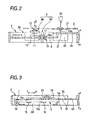
- Figs. 1 to 4 show a disk player in accordance with an embodiment of the invention.
- Vibration damping holes 31 and 32 are respectively provided penetratingly in a deck 2A substantially between a spindle motor fixing recessed groove 25 of the deck 2A and a guide rail 4 and between the recessed groove 25 and a guide shaft 5.
- the vibration damping hole 31 is formed in such a manner as to extend from a front end 4a of the guide rail 4 in a forward direction e with the same width t as the guide rail 4.
- the vibration damping hole 32 is formed in such a manner as to extend from the vicinity of a front end 5a of the guide shaft 5 in the forward direction e with substantially the same width t as the vibration damping hole 31.
- a reinforcing girder 33 traversing a substantially central portion of the vibration damping hole 32 on the guide shaft side is formed integrally with the deck 2A. Since arrangements other than those described above are substantially identical to those shown in Figs. 5 to 9, identical portions will be denoted by the same reference numerals, and a description thereof will be omitted.
- the vibration damping hole 31 on the guide rail side has the same width t as the guide rail 4 and is formed in such a manner as to extend from the front end 4a of the guide rail 4 in the forward direction, a connecting portion between the guide rail 4 and the deck 2A can be made short. Hence, it becomes possible to substantially damp the vibration transmitted from the guide rail 4 to the deck 2A.
- the vibration damping hole 31 on the guide rail side has the same width t as the guide rail 4 and is formed in such a manner as to extend from the front end 4a of the guide rail 4 in the forward direction, a rigidity of the
- the vibration damping hole 32 on the guide shaft side is formed with substantially the same width t as the vibration damping hole 31 on the guide rail side and is formed in such a manner as to extend from the vicinity of the front end 5a of the guide shaft 5 in the forward direction, a connecting portion between the guide shaft 5 and the deck 2A can be made short. Hence, it also becomes possible to substantially damp the vibration transmitted from the guide shaft 5 to the deck 2A.
- the vibration damping hole 31 and the vibration damping hole 32 are respectively provided penetratingly in the deck substantially between the spindle motor fixing recessed groove 25 of the deck and the guide rail 4 and between the spindle motor fixing recessed groove 25 and the guide shaft 5, a rigidity of the deck 2A, the guide rail 4 and the guide shaft 5 decreases, and a frequency of a infinitesimal vibration (vibration acceleration) of the central portion of the disk D sifts to a low frequency domain. Therefore, in the present invention, a disturbance of the focus servo characteristic in a normal working range ⁇ (1, 300 to 2,100 Hz) of the focusing coil 13 becomes smaller than that of the disk player shown in Figs. 5 to 9.
- the reinforcing girder 33 traversing a substantially central portion of the vibration damping hole 32 on the guide shaft side is formed integrally with the deck 2A, it is possible to prevent the deck 2A from becoming deflected due to the weight of the spindle motor 26 and reliably fix the spindle motor 26 to the deck 2A.
Landscapes
- Moving Of Heads (AREA)
- Moving Of The Head For Recording And Reproducing By Optical Means (AREA)
Applications Claiming Priority (2)
| Application Number | Priority Date | Filing Date | Title |
|---|---|---|---|
| JP2004001619A JP3859005B2 (ja) | 2004-01-07 | 2004-01-07 | ディスクプレーヤ |
| JP2004001619 | 2004-01-07 |
Publications (3)
| Publication Number | Publication Date |
|---|---|
| EP1553600A2 true EP1553600A2 (fr) | 2005-07-13 |
| EP1553600A3 EP1553600A3 (fr) | 2008-07-30 |
| EP1553600B1 EP1553600B1 (fr) | 2011-03-23 |
Family
ID=34587678
Family Applications (1)
| Application Number | Title | Priority Date | Filing Date |
|---|---|---|---|
| EP05000077A Not-in-force EP1553600B1 (fr) | 2004-01-07 | 2005-01-04 | Lecteur de disque |
Country Status (5)
| Country | Link |
|---|---|
| US (1) | US7406700B2 (fr) |
| EP (1) | EP1553600B1 (fr) |
| JP (1) | JP3859005B2 (fr) |
| CN (1) | CN100419899C (fr) |
| DE (1) | DE602005027013D1 (fr) |
Families Citing this family (2)
| Publication number | Priority date | Publication date | Assignee | Title |
|---|---|---|---|---|
| JP2011227955A (ja) * | 2010-04-16 | 2011-11-10 | Sanyo Electric Co Ltd | 光ピックアップ支持装置およびそれを備えた光ディスク装置 |
| JP5915038B2 (ja) * | 2011-09-06 | 2016-05-11 | 株式会社ニコン | レンズアセンブリ、レンズ鏡筒および撮像装置 |
Citations (1)
| Publication number | Priority date | Publication date | Assignee | Title |
|---|---|---|---|---|
| US6178155B1 (en) | 1996-07-12 | 2001-01-23 | Pioneer Electronic Corporation | Optical pickup with structure to reduce vibration |
Family Cites Families (20)
| Publication number | Priority date | Publication date | Assignee | Title |
|---|---|---|---|---|
| JPS56127962A (en) | 1980-03-13 | 1981-10-07 | Nec Corp | Signal level measuring device |
| JPH0240174A (ja) | 1988-07-29 | 1990-02-08 | Canon Electron Inc | 記録再生装置 |
| US5311497A (en) | 1991-09-30 | 1994-05-10 | Sony Corporation | Pickup feeding apparatus for a double-sided reproducing disc player |
| JPH0594627A (ja) | 1991-09-30 | 1993-04-16 | Sony Corp | デイスクプレーヤにおけるピツクアツプ移動機構 |
| JPH07161151A (ja) | 1993-12-03 | 1995-06-23 | Ricoh Co Ltd | 記録再生装置 |
| JP3158890B2 (ja) | 1994-09-30 | 2001-04-23 | 株式会社日立製作所 | 光ディスク駆動装置 |
| JP3339975B2 (ja) * | 1994-11-02 | 2002-10-28 | オリンパス光学工業株式会社 | リニアガイド装置 |
| JP3180310B2 (ja) * | 1995-04-28 | 2001-06-25 | 船井電機株式会社 | ディスクプレーヤーにおける吸振装置とその吸振装置の取り付け方法 |
| US5725931A (en) * | 1995-11-03 | 1998-03-10 | Minnesota Mining And Manufacturing Company | Constrained layer damper with slit(s) and/or cutout(s) |
| JPH09293369A (ja) * | 1996-04-26 | 1997-11-11 | Sony Corp | ディスクドライブ装置 |
| KR100188959B1 (ko) * | 1996-07-16 | 1999-06-01 | 윤종용 | 광디스크 드라이브의 진동흡수댐퍼 |
| KR100259150B1 (ko) * | 1997-11-28 | 2000-06-15 | 윤종용 | 광픽업 이송장치 |
| JP2000149278A (ja) | 1998-11-09 | 2000-05-30 | Mitsubishi Electric Corp | ディスク装置 |
| JP2000234650A (ja) * | 1999-02-15 | 2000-08-29 | Sony Corp | 振動吸収構造体及び防振支持方法 |
| CN2369325Y (zh) * | 1999-05-21 | 2000-03-15 | 仪宝资讯股份有限公司 | 可消除碟片晃动及共振效应的载体托盘构造 |
| JP2001035054A (ja) * | 1999-07-23 | 2001-02-09 | Sanyo Electric Co Ltd | カートリッジに収納されたディスクの記録又は再生装置 |
| US6646977B2 (en) * | 2001-07-10 | 2003-11-11 | Behavior Tech Computer Corporation | Resonance removing mechanism |
| TW569191B (en) * | 2002-01-15 | 2004-01-01 | Benq Corp | Apparatus for reducing running-noise in a disk drive |
| KR100505637B1 (ko) * | 2002-06-18 | 2005-08-03 | 삼성전자주식회사 | 흡진기를 채용한 디스크 드라이브 |
| US6826768B2 (en) * | 2002-10-08 | 2004-11-30 | Micro-Star Int'l Co., Ltd. | Optical compact disk drive with a vibration-and-noise attenuating mechanism |
-
2004
- 2004-01-07 JP JP2004001619A patent/JP3859005B2/ja not_active Expired - Fee Related
-
2005
- 2005-01-04 DE DE602005027013T patent/DE602005027013D1/de active Active
- 2005-01-04 EP EP05000077A patent/EP1553600B1/fr not_active Not-in-force
- 2005-01-06 US US11/029,488 patent/US7406700B2/en not_active Expired - Fee Related
- 2005-01-07 CN CNB2005100036146A patent/CN100419899C/zh not_active Expired - Fee Related
Patent Citations (1)
| Publication number | Priority date | Publication date | Assignee | Title |
|---|---|---|---|---|
| US6178155B1 (en) | 1996-07-12 | 2001-01-23 | Pioneer Electronic Corporation | Optical pickup with structure to reduce vibration |
Also Published As
| Publication number | Publication date |
|---|---|
| US7406700B2 (en) | 2008-07-29 |
| DE602005027013D1 (de) | 2011-05-05 |
| JP3859005B2 (ja) | 2006-12-20 |
| JP2005196857A (ja) | 2005-07-21 |
| EP1553600A3 (fr) | 2008-07-30 |
| CN100419899C (zh) | 2008-09-17 |
| CN1637924A (zh) | 2005-07-13 |
| US20050166216A1 (en) | 2005-07-28 |
| EP1553600B1 (fr) | 2011-03-23 |
Similar Documents
| Publication | Publication Date | Title |
|---|---|---|
| US6944103B2 (en) | Optical pick-up actuator | |
| JPH07105550A (ja) | 対物レンズ駆動装置 | |
| US7406700B2 (en) | Disk player for reducing focus servo characteristic | |
| US8284646B2 (en) | Objective lens driving device, control circuit, optical disc device and objective lens driving method | |
| US8199613B2 (en) | Objective lens actuator and a thin-sized optical pickup with magnetic circuit having different lengthed magnets | |
| US6351445B1 (en) | Optical pickup device | |
| KR20070026106A (ko) | 대물렌즈 구동장치, 광픽업, 광디스크 장치 및 진동억제방법 | |
| US20060190953A1 (en) | Disk recording/reproducer and method for fixing pickup of disc recorder/reproducer | |
| US6608802B1 (en) | Disk drive apparatus having improved power consumption | |
| US7203137B2 (en) | Optical pickup unit and optical disc device | |
| JP5067054B2 (ja) | 対物レンズ駆動装置 | |
| US20070121435A1 (en) | Objective-lens actuator, and information recording and reproducing apparatus | |
| JP4366404B2 (ja) | 対物レンズ駆動装置およびそれを用いたディスク装置 | |
| US20080159090A1 (en) | Optical pickup and disk drive device | |
| JP2926997B2 (ja) | 光ディスクドライブ | |
| JP6556606B2 (ja) | 光ピックアップ、及び光ディスク装置 | |
| US20090310447A1 (en) | Objective lens actuator | |
| JPWO2007077862A1 (ja) | 光ディスク駆動装置及び光ディスク装置 | |
| JP2009003990A (ja) | 光ディスク装置 | |
| JP2776672B2 (ja) | 分離型光学的情報記録再生装置 | |
| JP2009032316A (ja) | ピックアップ装置及び記録媒体再生装置 | |
| JP2013089278A (ja) | 光ピックアップ装置 | |
| JP2007323721A (ja) | トラバースユニットを備えたディスク装置 | |
| JP2001351256A (ja) | 対物レンズ駆動装置 | |
| KR20030021356A (ko) | 광픽업 액츄에이터의 지지구조 |
Legal Events
| Date | Code | Title | Description |
|---|---|---|---|
| PUAI | Public reference made under article 153(3) epc to a published international application that has entered the european phase |
Free format text: ORIGINAL CODE: 0009012 |
|
| AK | Designated contracting states |
Kind code of ref document: A2 Designated state(s): AT BE BG CH CY CZ DE DK EE ES FI FR GB GR HU IE IS IT LI LT LU MC NL PL PT RO SE SI SK TR |
|
| AX | Request for extension of the european patent |
Extension state: AL BA HR LV MK YU |
|
| PUAL | Search report despatched |
Free format text: ORIGINAL CODE: 0009013 |
|
| AK | Designated contracting states |
Kind code of ref document: A3 Designated state(s): AT BE BG CH CY CZ DE DK EE ES FI FR GB GR HU IE IS IT LI LT LU MC NL PL PT RO SE SI SK TR |
|
| AX | Request for extension of the european patent |
Extension state: AL BA HR LV MK YU |
|
| 17P | Request for examination filed |
Effective date: 20090129 |
|
| AKX | Designation fees paid |
Designated state(s): DE FR GB |
|
| 17Q | First examination report despatched |
Effective date: 20090311 |
|
| GRAP | Despatch of communication of intention to grant a patent |
Free format text: ORIGINAL CODE: EPIDOSNIGR1 |
|
| GRAS | Grant fee paid |
Free format text: ORIGINAL CODE: EPIDOSNIGR3 |
|
| GRAA | (expected) grant |
Free format text: ORIGINAL CODE: 0009210 |
|
| AK | Designated contracting states |
Kind code of ref document: B1 Designated state(s): DE FR GB |
|
| REG | Reference to a national code |
Ref country code: GB Ref legal event code: FG4D |
|
| REF | Corresponds to: |
Ref document number: 602005027013 Country of ref document: DE Date of ref document: 20110505 Kind code of ref document: P |
|
| REG | Reference to a national code |
Ref country code: DE Ref legal event code: R096 Ref document number: 602005027013 Country of ref document: DE Effective date: 20110505 |
|
| PLBE | No opposition filed within time limit |
Free format text: ORIGINAL CODE: 0009261 |
|
| STAA | Information on the status of an ep patent application or granted ep patent |
Free format text: STATUS: NO OPPOSITION FILED WITHIN TIME LIMIT |
|
| 26N | No opposition filed |
Effective date: 20111227 |
|
| REG | Reference to a national code |
Ref country code: DE Ref legal event code: R097 Ref document number: 602005027013 Country of ref document: DE Effective date: 20111227 |
|
| REG | Reference to a national code |
Ref country code: FR Ref legal event code: PLFP Year of fee payment: 12 |
|
| PGFP | Annual fee paid to national office [announced via postgrant information from national office to epo] |
Ref country code: GB Payment date: 20151230 Year of fee payment: 12 |
|
| PGFP | Annual fee paid to national office [announced via postgrant information from national office to epo] |
Ref country code: FR Payment date: 20151208 Year of fee payment: 12 |
|
| PGFP | Annual fee paid to national office [announced via postgrant information from national office to epo] |
Ref country code: DE Payment date: 20151229 Year of fee payment: 12 |
|
| REG | Reference to a national code |
Ref country code: DE Ref legal event code: R119 Ref document number: 602005027013 Country of ref document: DE |
|
| GBPC | Gb: european patent ceased through non-payment of renewal fee |
Effective date: 20170104 |
|
| REG | Reference to a national code |
Ref country code: FR Ref legal event code: ST Effective date: 20170929 |
|
| PG25 | Lapsed in a contracting state [announced via postgrant information from national office to epo] |
Ref country code: FR Free format text: LAPSE BECAUSE OF NON-PAYMENT OF DUE FEES Effective date: 20170131 |
|
| PG25 | Lapsed in a contracting state [announced via postgrant information from national office to epo] |
Ref country code: GB Free format text: LAPSE BECAUSE OF NON-PAYMENT OF DUE FEES Effective date: 20170104 Ref country code: DE Free format text: LAPSE BECAUSE OF NON-PAYMENT OF DUE FEES Effective date: 20170801 |