EP1553309B1 - Vorrichtung zur Befestigung eines Bauteils an Mantelrohre unterschiedlichen Durchmessers - Google Patents
Vorrichtung zur Befestigung eines Bauteils an Mantelrohre unterschiedlichen Durchmessers Download PDFInfo
- Publication number
- EP1553309B1 EP1553309B1 EP20050000027 EP05000027A EP1553309B1 EP 1553309 B1 EP1553309 B1 EP 1553309B1 EP 20050000027 EP20050000027 EP 20050000027 EP 05000027 A EP05000027 A EP 05000027A EP 1553309 B1 EP1553309 B1 EP 1553309B1
- Authority
- EP
- European Patent Office
- Prior art keywords
- jaws
- fastening
- fastening device
- equalizing
- steering column
- Prior art date
- Legal status (The legal status is an assumption and is not a legal conclusion. Google has not performed a legal analysis and makes no representation as to the accuracy of the status listed.)
- Expired - Lifetime
Links
Images


Classifications
-
- B—PERFORMING OPERATIONS; TRANSPORTING
- B60—VEHICLES IN GENERAL
- B60Q—ARRANGEMENT OF SIGNALLING OR LIGHTING DEVICES, THE MOUNTING OR SUPPORTING THEREOF OR CIRCUITS THEREFOR, FOR VEHICLES IN GENERAL
- B60Q1/00—Arrangement of optical signalling or lighting devices, the mounting or supporting thereof or circuits therefor
- B60Q1/02—Arrangement of optical signalling or lighting devices, the mounting or supporting thereof or circuits therefor the devices being primarily intended to illuminate the way ahead or to illuminate other areas of way or environments
- B60Q1/04—Arrangement of optical signalling or lighting devices, the mounting or supporting thereof or circuits therefor the devices being primarily intended to illuminate the way ahead or to illuminate other areas of way or environments the devices being headlights
- B60Q1/14—Arrangement of optical signalling or lighting devices, the mounting or supporting thereof or circuits therefor the devices being primarily intended to illuminate the way ahead or to illuminate other areas of way or environments the devices being headlights having dimming means
- B60Q1/1446—Arrangement of optical signalling or lighting devices, the mounting or supporting thereof or circuits therefor the devices being primarily intended to illuminate the way ahead or to illuminate other areas of way or environments the devices being headlights having dimming means controlled by mechanically actuated switches
- B60Q1/1453—Hand actuated switches
- B60Q1/1461—Multifunction switches for dimming headlights and controlling additional devices, e.g. for controlling direction indicating lights
-
- B—PERFORMING OPERATIONS; TRANSPORTING
- B60—VEHICLES IN GENERAL
- B60R—VEHICLES, VEHICLE FITTINGS, OR VEHICLE PARTS, NOT OTHERWISE PROVIDED FOR
- B60R13/00—Elements for body-finishing, identifying, or decorating; Arrangements or adaptations for advertising purposes
- B60R13/02—Internal Trim mouldings ; Internal Ledges; Wall liners for passenger compartments; Roof liners
- B60R13/0206—Arrangements of fasteners and clips specially adapted for attaching inner vehicle liners or mouldings
-
- B—PERFORMING OPERATIONS; TRANSPORTING
- B60—VEHICLES IN GENERAL
- B60R—VEHICLES, VEHICLE FITTINGS, OR VEHICLE PARTS, NOT OTHERWISE PROVIDED FOR
- B60R11/00—Arrangements for holding or mounting articles, not otherwise provided for
- B60R2011/0001—Arrangements for holding or mounting articles, not otherwise provided for characterised by position
- B60R2011/0003—Arrangements for holding or mounting articles, not otherwise provided for characterised by position inside the vehicle
- B60R2011/001—Vehicle control means, e.g. steering-wheel or column
-
- F—MECHANICAL ENGINEERING; LIGHTING; HEATING; WEAPONS; BLASTING
- F16—ENGINEERING ELEMENTS AND UNITS; GENERAL MEASURES FOR PRODUCING AND MAINTAINING EFFECTIVE FUNCTIONING OF MACHINES OR INSTALLATIONS; THERMAL INSULATION IN GENERAL
- F16B—DEVICES FOR FASTENING OR SECURING CONSTRUCTIONAL ELEMENTS OR MACHINE PARTS TOGETHER, e.g. NAILS, BOLTS, CIRCLIPS, CLAMPS, CLIPS OR WEDGES; JOINTS OR JOINTING
- F16B21/00—Means for preventing relative axial movement of a pin, spigot, shaft or the like and a member surrounding it; Stud-and-socket releasable fastenings
- F16B21/02—Releasable fastening devices locking by rotation
-
- Y—GENERAL TAGGING OF NEW TECHNOLOGICAL DEVELOPMENTS; GENERAL TAGGING OF CROSS-SECTIONAL TECHNOLOGIES SPANNING OVER SEVERAL SECTIONS OF THE IPC; TECHNICAL SUBJECTS COVERED BY FORMER USPC CROSS-REFERENCE ART COLLECTIONS [XRACs] AND DIGESTS
- Y10—TECHNICAL SUBJECTS COVERED BY FORMER USPC
- Y10T—TECHNICAL SUBJECTS COVERED BY FORMER US CLASSIFICATION
- Y10T292/00—Closure fasteners
- Y10T292/20—Clamps
Definitions
- the invention relates to a device for fastening a component to a casing tube, as seen from US Pat. No. 6,520,464
- the invention is directed to a fastening device for a steering column switch or jacket tube switch module.
- the steering device of a motor vehicle usually comprises a steering shaft mounted in a jacket tube, which is connected to the steering wheel. On the jacket tube various components are attached, which serve the control and operation of vehicle functions.
- the steering column switch or jacket tube switch modules usually each comprise a turn signal switch and a wiper switch for the stepwise actuation of the windscreen wiper and for the switching functions of the windscreen washer system.
- various interfaces and evaluation units for example, to steering power assistance systems, driving angle and steering angle sensors may be arranged.
- the object of the invention is therefore to avoid these disadvantages and to provide a usable for different types of vehicle mounting device of the type mentioned.
- the invention thus provides a fastening device, for example, for a jacket tube switch module which can be used for at least two different jacket tubes with different outer diameter.
- a fastening device for example, for a jacket tube switch module which can be used for at least two different jacket tubes with different outer diameter.
- the compensation jaws which are movable in the receiving sleeve and reduce the original large receiving cross-section or left-hand diameter of the fastening sleeve to a smaller receiving cross-section when they lie in the receiving section of the fastening sleeve.
- the compensating jaws When moving the compensating jaws, these disappear into the recesses provided on the mounting sleeve, so that the receiving cross-section is increased to the original size and the mounting sleeve fits on a jacket tube with a larger outer diameter.
- the fastening sleeve according to the invention is thus suitable in an advantageous manner for attachment to various jacket tubes. Since the difference of the receiving cross sections or the casing pipe diameter is determined by the thickness of the compensating jaws, the matching Jacket pipes are easily selected.
- the balancing parts of the fastening device according to the invention are also produced in a simple manner by plastic injection molding. Thus, it is also possible to dispense with the storage of different fastening devices with different clamping diameters. The storage can rather be reduced to the different balancing parts. This also considerable cost savings can be realized.
- the compensating jaws of the fastening device according to the invention are preferably interconnected by webs.
- the webs may for example be formed of spring steel. However, it is particularly preferred if the webs and the compensating jaws are formed integrally with each other from plastic. The webs stabilize the compensation part and increase the mechanical strength. When using plastic as the material for the webs a particularly simple and inexpensive production is possible.
- the compensation part has molded tabs which facilitate a displacement or rotation of the compensation jaws.
- the tabs which are preferably integrally formed in the area of the compensating jaws, can also serve as points of attack for a tool and thus facilitate the assembly and / or actuation of the compensating part.
- the receiving portion of the mounting sleeve for the jacket tube is formed in cross-section circular segment.
- the shape of the receiving portion of the mounting sleeve then corresponds to the shape of the jacket tube, so that the cross-sectionally circular receiving portion abuts firmly on the outer circumference of the jacket tube and this clamps in the first receiving cross-section, when the balancing jaws are in the first position in which they in the radial protruding bulges are added to the mounting sleeve.
- the compensating jaws are preferably arranged rotatably about a central axis of the fastening sleeve, wherein the shape of the Balancing jaws preferably corresponds to the shape of the bulge.
- the bulges on inclined side walls and the compensating jaws on tapered side surfaces and a concave, the jacket tube facing clamping surface. They can be easily unscrew from the bulges and transferred to the second position. In this position, a jacket tube can be used with a smaller outer diameter and is held securely between the concave clamping surfaces of the balancing jaws.
- the compensating part with the compensating jaws arranged thereon is preferably a component which is separate from the fastening sleeve. So that it is securely held in the sleeve, it is preferably under a bias of the type that the compensating jaws acted upon in the first position with spring force and are held in the bulges.
- the spring force can be generated for example by the fact that the compensating part is formed with the webs and the compensating jaws in the form of a split ring whose inner diameter is slightly larger than that of the first receiving cross-section.
- the balancing part can only assume two defined positions on the fastening sleeve. These positions can be realized for example by end stops and / or a corresponding shape of the compensating part. For example, a shoulder may be provided on the fastening sleeve, against which a projection formed on the compensating part abuts. It is also possible to provide a locking connection between the fastening sleeve and the compensation part, which fixes the compensation part in the first or second position.
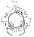
- the in the FIGS. 1 to 6 illustrated fastening device 10 includes a mounting sleeve 12 and a compensation member 14 with balancing jaws 16 which are rotatably received about a central axis of the mounting sleeve 12.
- the mounting sleeve 12 has a plurality of, in the embodiment shown here in cross-section circular segment-shaped receiving portions 18, in which a casing tube 20 is received with a large outer diameter.
- the outer surface of the casing tube 20 is fixed in the receiving portions 18 and clearance on the wall of the mounting sleeve 12, so that the fastening device 10 is securely fixed to the casing tube 20.
- the receiving portions 18 thus define a first receiving cross section, which corresponds to the outer diameter of the casing tube 20.
- bulges 22 Adjacent to the cross-sectionally circular receiving portions 18 of the mounting sleeve 12 bulges 22 are formed, which project radially and extend along the mounting sleeve 12.
- the shape of the bulges is adapted to the shape of the balancing jaws.
- the equalizing jaws 22 are provided with bevelled side surfaces 24 which rest against corresponding oblique side walls 26 of the bulges 22.
- the compensating jaws 16 also have a jacket tube 20 facing concave clamping surface 28 which abuts at least pointwise on the casing tube 20 in the position shown here of the compensating part 14. As a result, the clamping of the jacket tube 20 is additionally reinforced in the first receiving cross section of the fastening sleeve.
- the balancing jaws 16 are connected to increase the mechanical stability of the compensating part 14 and to improve the handling by webs 30 with each other.
- one or more actuating tabs 32 are further formed to allow a rotation of the compensating part 14 and the compensating jaws 16 in the mounting sleeve 12 by hand or by means of a special tool.
- the actuating tabs 32 are preferably arranged on a vehicle-side edge of the compensating part 14 and adjoin a fastening flange 12 which extends radially from the fastening sleeve 12 and is formed as a carrier plate.
- On the mounting flange 34 may be provided on the component side several attachment points 36 for connection to the other component (not shown here).
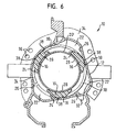
- FIGS. 4 to 6 show the fastening device 10 according to the invention, in which a jacket tube 20 'is taken with a smaller outer diameter.
- the compensating part 14 with the compensating jaws 16 is here unscrewed from the first position to a second position, in which the compensating jaws 16 lie outside the bulges 22 and thus at least partially in the receiving sections 18.
- the concave clamping surfaces 28 of the balancing jaws 16 define a second receiving cross section, which is smaller than that defined by the receiving portions 18 first receiving cross-section and the outer diameter of the smaller casing tube 20 'corresponds.
- the jacket tube 20 ' is in the in the FIGS.
- the compensating part 14 which is preferably produced as a plastic injection-molded part, is first inserted into the fastening sleeve 12 with the compensating jaws 16 connected to one another by webs 30.
- the compensating jaws 16 in this case lie in the bulges 22 of the fastening sleeve 12 and extend in the axial direction along the inner wall of the fastening sleeve 12.
- the webs 30 connect the balancing jaws 16 preferably at the vehicle-side end of the balancing jaws 16 and adjoin there to a mounting flange 34 of the mounting sleeve 12 ,
- the webs 30 and the compensating jaws 16 are in this case in the form of a split ring whose inner diameter, measured at the enclosed by the clamping surfaces 28 circular area, is slightly larger than the defined by the receiving portions 18 receiving cross section of the mounting sleeve 12.
- the split ring-shaped compensation member 14 must therefore Inserting the balancing jaws 16 are slightly compressed in the bulges 22. As a result, a bias voltage is generated which holds the balancing jaws 14 securely in the bulges 22.
- the jacket tube 20 with the larger outer diameter of the through the receiving portions 18th defined receiving cross section corresponds to be inserted into the mounting sleeve 12.
- the compensation member 14 from the in FIGS. 1 to 3 shown in the first position in which the balancing jaws lie in the bulges 22, unscrewed and brought into a second position in which the balancing jaws are at least partially disposed in the receiving portions 18.
- the rotation of the compensating part 14 can be done either by hand or with a matched tool on the arranged on the webs 30 and the balancing jaws 16 actuating lugs 32.
- the compensation member 14 then comes to lie in a position in the FIGS. 4 to 6 is shown.
- the receiving cross-section of the fastening device 10 is then defined by the clamping surfaces 28 and corresponds to the outer diameter of the smaller jacket tube 20 '.
Landscapes
- Engineering & Computer Science (AREA)
- Mechanical Engineering (AREA)
- Steering Controls (AREA)
- Mutual Connection Of Rods And Tubes (AREA)
- Clamps And Clips (AREA)
- Supports For Pipes And Cables (AREA)
- Quick-Acting Or Multi-Walled Pipe Joints (AREA)
- Earth Drilling (AREA)
- Joints With Sleeves (AREA)
Priority Applications (1)
| Application Number | Priority Date | Filing Date | Title |
|---|---|---|---|
| PL05000027T PL1553309T3 (pl) | 2004-01-07 | 2005-01-03 | Urządzenie do mocowania elementu konstrukcyjnego na rurach osłonowych o różnej średnicy |
Applications Claiming Priority (2)
| Application Number | Priority Date | Filing Date | Title |
|---|---|---|---|
| DE202004000110U | 2004-01-07 | ||
| DE202004000110U DE202004000110U1 (de) | 2004-01-07 | 2004-01-07 | Vorrichtung zur Befestigung eines Bauteils an einem Mantelrohr |
Publications (3)
| Publication Number | Publication Date |
|---|---|
| EP1553309A2 EP1553309A2 (de) | 2005-07-13 |
| EP1553309A3 EP1553309A3 (de) | 2006-10-04 |
| EP1553309B1 true EP1553309B1 (de) | 2009-12-09 |
Family
ID=32892548
Family Applications (1)
| Application Number | Title | Priority Date | Filing Date |
|---|---|---|---|
| EP20050000027 Expired - Lifetime EP1553309B1 (de) | 2004-01-07 | 2005-01-03 | Vorrichtung zur Befestigung eines Bauteils an Mantelrohre unterschiedlichen Durchmessers |
Country Status (10)
| Country | Link |
|---|---|
| US (1) | US7571664B2 (pl) |
| EP (1) | EP1553309B1 (pl) |
| JP (1) | JP4063823B2 (pl) |
| CN (1) | CN1299932C (pl) |
| AT (1) | ATE451557T1 (pl) |
| BR (1) | BRPI0500027A (pl) |
| DE (3) | DE202004000110U1 (pl) |
| ES (1) | ES2336217T3 (pl) |
| MX (1) | MXPA05000479A (pl) |
| PL (1) | PL1553309T3 (pl) |
Families Citing this family (10)
| Publication number | Priority date | Publication date | Assignee | Title |
|---|---|---|---|---|
| EP1903387B1 (en) | 2005-07-01 | 2011-01-26 | Nikon Corporation | Projection device |
| ITPD20050357A1 (it) * | 2005-12-05 | 2007-06-06 | Alu Spa | Dispositivo a morsetto, particolarmente per il fissaggio su elementi a sezione variabile |
| CN101680468B (zh) * | 2007-05-08 | 2012-06-13 | 泰尔茂株式会社 | 夹持装置 |
| CN101623756B (zh) * | 2008-07-08 | 2010-12-29 | 上海发那科机器人有限公司 | 一种轴套定位结构 |
| US8132828B2 (en) * | 2008-09-11 | 2012-03-13 | Trw Automotive U.S. Llc | Apparatus and method for connecting a control module to a steering column |
| DE102009038316A1 (de) * | 2009-08-21 | 2011-02-24 | Thyssenkrupp Presta Ag | Verfahren zur Herstellung eines einen Abschnitt einer Lenkspindel bildenden Lenkspindelteils |
| BR112012010585B1 (pt) * | 2009-11-05 | 2019-06-25 | Schaeffler Technologies AG & Co. KG | Cilindro hidráulico. |
| CN102822034B (zh) * | 2011-04-04 | 2015-05-27 | 日本精工株式会社 | 转向装置 |
| JP5776627B2 (ja) * | 2011-08-23 | 2015-09-09 | 日本精工株式会社 | 電動式パワーステアリング装置用ステアリングコラムの支持装置及び支持ブラケットの製造方法 |
| DE102013018149A1 (de) * | 2013-12-04 | 2015-06-11 | Daimler Ag | Lenksäulenanordnung Mantelrohr für eine Lenksäulenanordnung, und Fahrzeug mit einer Lenksäulenanordnung |
Family Cites Families (18)
| Publication number | Priority date | Publication date | Assignee | Title |
|---|---|---|---|---|
| GB1182213A (en) * | 1968-03-01 | 1970-02-25 | Vif Vitaloni S A S Di Vitaloni | Switching Control Apparatus for Attachment to a Motor Vehicle Steering Column. |
| JPS58110336A (ja) * | 1981-12-24 | 1983-06-30 | Nissan Motor Co Ltd | スイツチボツクスの取付構造 |
| JPS58150230A (ja) * | 1982-03-03 | 1983-09-06 | ナイルス部品株式会社 | 車両用コラムスイツチの取付装置 |
| US4598562A (en) * | 1983-05-09 | 1986-07-08 | Freeman John T | Steering column protective jacket |
| US4857706A (en) * | 1988-02-29 | 1989-08-15 | Diamond Paul J | Ironing accessory |
| IL105065A (en) * | 1992-03-28 | 1995-05-26 | Smiths Ind Public Ltd | author |
| FR2718095B1 (fr) * | 1994-03-31 | 1996-05-15 | Valeo Electronique | Support de commutateurs pour colonne de direction d'un véhicule automobile. |
| FR2721432B1 (fr) | 1994-06-15 | 1996-09-13 | Jaeger | Système de commutation sous volant pour véhicules automobiles. |
| US5704633A (en) * | 1995-12-19 | 1998-01-06 | United Technologies Automotive Systems, Inc. | Modular clock spring arrangement |
| JP3333387B2 (ja) * | 1996-05-29 | 2002-10-15 | ナイルス部品株式会社 | スイッチの取付構造 |
| FR2749354B1 (fr) * | 1996-05-30 | 1998-08-07 | Valeo Electronique | Support de commutateurs a collier de fixation pour vehicule automobile |
| DE19711561C2 (de) * | 1997-03-20 | 1999-07-22 | Delco Electronics Europ Gmbh | An einer Lenksäule eines Kraftfahrzeugs befestigbare Haltevorrichtung |
| US6236004B1 (en) * | 1998-03-20 | 2001-05-22 | Delco Electronics Europe Gmbh | Steering column assembly |
| US6179512B1 (en) * | 1998-05-29 | 2001-01-30 | Power Tool Holders Incorporated | Collet nut |
| US6520464B1 (en) * | 2000-06-12 | 2003-02-18 | Rockwell Automation Technologies, Inc. | Assembly for facilitating mounting and removal of an article |
| ITPD20010283A1 (it) * | 2001-12-04 | 2003-06-04 | Manfrotto Lino & C Spa | Dispositivo di connessione per strutture espositive |
| EP1500561B1 (de) | 2003-07-22 | 2006-09-13 | TRW Automotive Safety Systems GmbH | Fahrzeuglenkvorrichtung mit feststehendem Mittelteil |
| US7290789B2 (en) * | 2003-07-22 | 2007-11-06 | Trw Automotive Safety Systems Gmbh | Vehicle steering device with stationary central part |
-
2004
- 2004-01-07 DE DE202004000110U patent/DE202004000110U1/de not_active Expired - Lifetime
-
2005
- 2005-01-03 ES ES05000027T patent/ES2336217T3/es not_active Expired - Lifetime
- 2005-01-03 EP EP20050000027 patent/EP1553309B1/de not_active Expired - Lifetime
- 2005-01-03 DE DE200550008657 patent/DE502005008657D1/de not_active Expired - Lifetime
- 2005-01-03 DE DE200510000625 patent/DE102005000625A1/de not_active Ceased
- 2005-01-03 PL PL05000027T patent/PL1553309T3/pl unknown
- 2005-01-03 AT AT05000027T patent/ATE451557T1/de not_active IP Right Cessation
- 2005-01-05 BR BRPI0500027 patent/BRPI0500027A/pt not_active IP Right Cessation
- 2005-01-06 US US11/030,404 patent/US7571664B2/en not_active Expired - Fee Related
- 2005-01-06 JP JP2005001140A patent/JP4063823B2/ja not_active Expired - Fee Related
- 2005-01-07 MX MXPA05000479A patent/MXPA05000479A/es active IP Right Grant
- 2005-01-07 CN CNB2005100041233A patent/CN1299932C/zh not_active Expired - Fee Related
Also Published As
| Publication number | Publication date |
|---|---|
| JP2005193899A (ja) | 2005-07-21 |
| EP1553309A3 (de) | 2006-10-04 |
| MXPA05000479A (es) | 2005-08-16 |
| CN1299932C (zh) | 2007-02-14 |
| DE502005008657D1 (de) | 2010-01-21 |
| DE102005000625A1 (de) | 2005-08-04 |
| ATE451557T1 (de) | 2009-12-15 |
| ES2336217T3 (es) | 2010-04-09 |
| EP1553309A2 (de) | 2005-07-13 |
| DE202004000110U1 (de) | 2004-08-19 |
| CN1640728A (zh) | 2005-07-20 |
| US20050184536A1 (en) | 2005-08-25 |
| PL1553309T3 (pl) | 2010-05-31 |
| JP4063823B2 (ja) | 2008-03-19 |
| US7571664B2 (en) | 2009-08-11 |
| BRPI0500027A (pt) | 2005-09-06 |
Similar Documents
| Publication | Publication Date | Title |
|---|---|---|
| EP2590840B1 (de) | Befestigungsanordnung zum befestigen von kraftfahrzeugbauteilen | |
| EP2739519B1 (de) | Lenkungsanordnung | |
| EP3717786B1 (de) | Toleranzausgleichsanordnung mit klemmsicherung | |
| EP3350034B1 (de) | Lagervorrichtung und elektromechanischer bremskraftverstärker | |
| EP2861480B1 (de) | Verstellvorrichtung für ein fahrwerk eines fahrzeugs mit gleitstein | |
| EP2734742B1 (de) | Vorrichtung zur lagesicherung einer einheit | |
| EP1553309B1 (de) | Vorrichtung zur Befestigung eines Bauteils an Mantelrohre unterschiedlichen Durchmessers | |
| EP0328759A1 (de) | Anordnung zur Befestigung eines Bremskraftverstärkers | |
| EP3368392B1 (de) | Lenksäule für ein kraftfahrzeug und verfahren zur herstellung einer lenksäule | |
| EP3426457B1 (de) | Verfahren zur herstellung einer längenveränderbaren lenkwelle und spritzgiessvorrichtung zur durchführung des verfahrens | |
| WO2009030480A2 (de) | Befestiger | |
| WO2007131830A1 (de) | Vorrichtung und verfahren zur befestigung eines wischermotors an ein wischergestänge | |
| EP2020362A2 (de) | Elektrische Lenkvorrichtung für Kraftfahrzeuge | |
| EP3585671A1 (de) | Lager für eine lenkspindel und lenksäule für ein kraftfahrzeug | |
| DE102019211673A1 (de) | Befestigungselement für ein Gehäuse zum Befestigen des Gehäuses an einer Trägerstruktur und Montagesystem | |
| DE10222761A1 (de) | Zahnstangenlenkung mit Stellungserfassung | |
| DE102008004324B4 (de) | Scheibenwischeranlage an einem Fahrzeug | |
| EP0829407B1 (de) | Kolben/Zylinder-Anordnung | |
| DE102022132444A1 (de) | Biegebegrenzer für eine lenkzahnstange und diesen umfassende lenkbaugruppe | |
| EP3969916B1 (de) | Drehzahlsensor, fixiereinrichtung für einen drehzahlsensor, aufnahmevorrichtung für einen drehzahlsensor, sensorsystem mit einer aufnahmevorrichtung und einem drehzahlsensor und verfahren zum verdrehsicheren positionieren eines drehzahlsensors | |
| DE102004044055A1 (de) | Toleranzausgleichsvorrichtung für zwei miteinander zu verschraubende Bauteile | |
| EP2067672B1 (de) | Scheibenwischvorrichtung für ein Kraftfahrzeug | |
| EP1676761B1 (de) | Scheibenwischvorrichtung | |
| EP1674751B1 (de) | Ausrückvorrichtung | |
| EP1493648A2 (de) | Lenkvorrichtung für ein Kraftfahrzeug |
Legal Events
| Date | Code | Title | Description |
|---|---|---|---|
| PUAI | Public reference made under article 153(3) epc to a published international application that has entered the european phase |
Free format text: ORIGINAL CODE: 0009012 |
|
| AK | Designated contracting states |
Kind code of ref document: A2 Designated state(s): AT BE BG CH CY CZ DE DK EE ES FI FR GB GR HU IE IS IT LI LT LU MC NL PL PT RO SE SI SK TR |
|
| AX | Request for extension of the european patent |
Extension state: AL BA HR LV MK YU |
|
| PUAL | Search report despatched |
Free format text: ORIGINAL CODE: 0009013 |
|
| AK | Designated contracting states |
Kind code of ref document: A3 Designated state(s): AT BE BG CH CY CZ DE DK EE ES FI FR GB GR HU IE IS IT LI LT LU MC NL PL PT RO SE SI SK TR |
|
| AX | Request for extension of the european patent |
Extension state: AL BA HR LV MK YU |
|
| 17P | Request for examination filed |
Effective date: 20070329 |
|
| AKX | Designation fees paid |
Designated state(s): AT BE BG CH CY CZ DE DK EE ES FI FR GB GR HU IE IS IT LI LT LU MC NL PL PT RO SE SI SK TR |
|
| 17Q | First examination report despatched |
Effective date: 20081125 |
|
| GRAP | Despatch of communication of intention to grant a patent |
Free format text: ORIGINAL CODE: EPIDOSNIGR1 |
|
| GRAS | Grant fee paid |
Free format text: ORIGINAL CODE: EPIDOSNIGR3 |
|
| GRAA | (expected) grant |
Free format text: ORIGINAL CODE: 0009210 |
|
| AK | Designated contracting states |
Kind code of ref document: B1 Designated state(s): AT BE BG CH CY CZ DE DK EE ES FI FR GB GR HU IE IS IT LI LT LU MC NL PL PT RO SE SI SK TR |
|
| REG | Reference to a national code |
Ref country code: GB Ref legal event code: FG4D Free format text: NOT ENGLISH |
|
| REG | Reference to a national code |
Ref country code: CH Ref legal event code: EP |
|
| RAP2 | Party data changed (patent owner data changed or rights of a patent transferred) |
Owner name: TRW AUTOMOTIVE ELECTRONICS & COMPONENTS GMBH |
|
| REG | Reference to a national code |
Ref country code: IE Ref legal event code: FG4D |
|
| REF | Corresponds to: |
Ref document number: 502005008657 Country of ref document: DE Date of ref document: 20100121 Kind code of ref document: P |
|
| NLT2 | Nl: modifications (of names), taken from the european patent patent bulletin |
Owner name: TRW AUTOMOTIVE ELECTRONICS & COMPONENTS GMBH Effective date: 20091216 |
|
| REG | Reference to a national code |
Ref country code: ES Ref legal event code: FG2A Ref document number: 2336217 Country of ref document: ES Kind code of ref document: T3 |
|
| REG | Reference to a national code |
Ref country code: NL Ref legal event code: VDEP Effective date: 20091209 |
|
| PG25 | Lapsed in a contracting state [announced via postgrant information from national office to epo] |
Ref country code: LT Free format text: LAPSE BECAUSE OF FAILURE TO SUBMIT A TRANSLATION OF THE DESCRIPTION OR TO PAY THE FEE WITHIN THE PRESCRIBED TIME-LIMIT Effective date: 20091209 Ref country code: SE Free format text: LAPSE BECAUSE OF FAILURE TO SUBMIT A TRANSLATION OF THE DESCRIPTION OR TO PAY THE FEE WITHIN THE PRESCRIBED TIME-LIMIT Effective date: 20091209 Ref country code: FI Free format text: LAPSE BECAUSE OF FAILURE TO SUBMIT A TRANSLATION OF THE DESCRIPTION OR TO PAY THE FEE WITHIN THE PRESCRIBED TIME-LIMIT Effective date: 20091209 |
|
| LTIE | Lt: invalidation of european patent or patent extension |
Effective date: 20091209 |
|
| PG25 | Lapsed in a contracting state [announced via postgrant information from national office to epo] |
Ref country code: SI Free format text: LAPSE BECAUSE OF FAILURE TO SUBMIT A TRANSLATION OF THE DESCRIPTION OR TO PAY THE FEE WITHIN THE PRESCRIBED TIME-LIMIT Effective date: 20091209 |
|
| REG | Reference to a national code |
Ref country code: PL Ref legal event code: T3 |
|
| REG | Reference to a national code |
Ref country code: IE Ref legal event code: FD4D |
|
| PG25 | Lapsed in a contracting state [announced via postgrant information from national office to epo] |
Ref country code: IS Free format text: LAPSE BECAUSE OF FAILURE TO SUBMIT A TRANSLATION OF THE DESCRIPTION OR TO PAY THE FEE WITHIN THE PRESCRIBED TIME-LIMIT Effective date: 20100409 Ref country code: PT Free format text: LAPSE BECAUSE OF FAILURE TO SUBMIT A TRANSLATION OF THE DESCRIPTION OR TO PAY THE FEE WITHIN THE PRESCRIBED TIME-LIMIT Effective date: 20100409 Ref country code: NL Free format text: LAPSE BECAUSE OF FAILURE TO SUBMIT A TRANSLATION OF THE DESCRIPTION OR TO PAY THE FEE WITHIN THE PRESCRIBED TIME-LIMIT Effective date: 20091209 Ref country code: RO Free format text: LAPSE BECAUSE OF FAILURE TO SUBMIT A TRANSLATION OF THE DESCRIPTION OR TO PAY THE FEE WITHIN THE PRESCRIBED TIME-LIMIT Effective date: 20091209 Ref country code: EE Free format text: LAPSE BECAUSE OF FAILURE TO SUBMIT A TRANSLATION OF THE DESCRIPTION OR TO PAY THE FEE WITHIN THE PRESCRIBED TIME-LIMIT Effective date: 20091209 Ref country code: BG Free format text: LAPSE BECAUSE OF FAILURE TO SUBMIT A TRANSLATION OF THE DESCRIPTION OR TO PAY THE FEE WITHIN THE PRESCRIBED TIME-LIMIT Effective date: 20100309 Ref country code: IE Free format text: LAPSE BECAUSE OF FAILURE TO SUBMIT A TRANSLATION OF THE DESCRIPTION OR TO PAY THE FEE WITHIN THE PRESCRIBED TIME-LIMIT Effective date: 20091209 |
|
| BERE | Be: lapsed |
Owner name: TRW AUTOMOTIVE ELECTRONICS & COMPONENTS G.M.B.H. Effective date: 20100131 |
|
| PG25 | Lapsed in a contracting state [announced via postgrant information from national office to epo] |
Ref country code: MC Free format text: LAPSE BECAUSE OF NON-PAYMENT OF DUE FEES Effective date: 20100131 Ref country code: SK Free format text: LAPSE BECAUSE OF FAILURE TO SUBMIT A TRANSLATION OF THE DESCRIPTION OR TO PAY THE FEE WITHIN THE PRESCRIBED TIME-LIMIT Effective date: 20091209 |
|
| PGFP | Annual fee paid to national office [announced via postgrant information from national office to epo] |
Ref country code: PL Payment date: 20100201 Year of fee payment: 6 |
|
| REG | Reference to a national code |
Ref country code: CH Ref legal event code: PL |
|
| PLBE | No opposition filed within time limit |
Free format text: ORIGINAL CODE: 0009261 |
|
| STAA | Information on the status of an ep patent application or granted ep patent |
Free format text: STATUS: NO OPPOSITION FILED WITHIN TIME LIMIT |
|
| REG | Reference to a national code |
Ref country code: FR Ref legal event code: ST Effective date: 20100930 |
|
| PG25 | Lapsed in a contracting state [announced via postgrant information from national office to epo] |
Ref country code: FR Free format text: LAPSE BECAUSE OF NON-PAYMENT OF DUE FEES Effective date: 20100209 Ref country code: LI Free format text: LAPSE BECAUSE OF NON-PAYMENT OF DUE FEES Effective date: 20100131 Ref country code: GR Free format text: LAPSE BECAUSE OF FAILURE TO SUBMIT A TRANSLATION OF THE DESCRIPTION OR TO PAY THE FEE WITHIN THE PRESCRIBED TIME-LIMIT Effective date: 20100310 Ref country code: CY Free format text: LAPSE BECAUSE OF FAILURE TO SUBMIT A TRANSLATION OF THE DESCRIPTION OR TO PAY THE FEE WITHIN THE PRESCRIBED TIME-LIMIT Effective date: 20091209 Ref country code: CH Free format text: LAPSE BECAUSE OF NON-PAYMENT OF DUE FEES Effective date: 20100131 |
|
| 26N | No opposition filed |
Effective date: 20100910 |
|
| GBPC | Gb: european patent ceased through non-payment of renewal fee |
Effective date: 20100309 |
|
| PG25 | Lapsed in a contracting state [announced via postgrant information from national office to epo] |
Ref country code: CZ Free format text: LAPSE BECAUSE OF NON-PAYMENT OF DUE FEES Effective date: 20100103 |
|
| PG25 | Lapsed in a contracting state [announced via postgrant information from national office to epo] |
Ref country code: DK Free format text: LAPSE BECAUSE OF FAILURE TO SUBMIT A TRANSLATION OF THE DESCRIPTION OR TO PAY THE FEE WITHIN THE PRESCRIBED TIME-LIMIT Effective date: 20091209 |
|
| PG25 | Lapsed in a contracting state [announced via postgrant information from national office to epo] |
Ref country code: BE Free format text: LAPSE BECAUSE OF NON-PAYMENT OF DUE FEES Effective date: 20100131 |
|
| REG | Reference to a national code |
Ref country code: ES Ref legal event code: FD2A Effective date: 20110301 |
|
| PG25 | Lapsed in a contracting state [announced via postgrant information from national office to epo] |
Ref country code: IT Free format text: LAPSE BECAUSE OF NON-PAYMENT OF DUE FEES Effective date: 20100103 Ref country code: GB Free format text: LAPSE BECAUSE OF NON-PAYMENT OF DUE FEES Effective date: 20100309 |
|
| PG25 | Lapsed in a contracting state [announced via postgrant information from national office to epo] |
Ref country code: AT Free format text: LAPSE BECAUSE OF NON-PAYMENT OF DUE FEES Effective date: 20100103 |
|
| PG25 | Lapsed in a contracting state [announced via postgrant information from national office to epo] |
Ref country code: ES Free format text: LAPSE BECAUSE OF NON-PAYMENT OF DUE FEES Effective date: 20110224 |
|
| PG25 | Lapsed in a contracting state [announced via postgrant information from national office to epo] |
Ref country code: ES Free format text: LAPSE BECAUSE OF NON-PAYMENT OF DUE FEES Effective date: 20100104 |
|
| REG | Reference to a national code |
Ref country code: PL Ref legal event code: LAPE |
|
| PG25 | Lapsed in a contracting state [announced via postgrant information from national office to epo] |
Ref country code: PL Free format text: LAPSE BECAUSE OF NON-PAYMENT OF DUE FEES Effective date: 20110103 |
|
| PG25 | Lapsed in a contracting state [announced via postgrant information from national office to epo] |
Ref country code: LU Free format text: LAPSE BECAUSE OF NON-PAYMENT OF DUE FEES Effective date: 20100103 Ref country code: HU Free format text: LAPSE BECAUSE OF FAILURE TO SUBMIT A TRANSLATION OF THE DESCRIPTION OR TO PAY THE FEE WITHIN THE PRESCRIBED TIME-LIMIT Effective date: 20100610 |
|
| PG25 | Lapsed in a contracting state [announced via postgrant information from national office to epo] |
Ref country code: TR Free format text: LAPSE BECAUSE OF FAILURE TO SUBMIT A TRANSLATION OF THE DESCRIPTION OR TO PAY THE FEE WITHIN THE PRESCRIBED TIME-LIMIT Effective date: 20091209 |
|
| PGFP | Annual fee paid to national office [announced via postgrant information from national office to epo] |
Ref country code: DE Payment date: 20180129 Year of fee payment: 14 |
|
| REG | Reference to a national code |
Ref country code: DE Ref legal event code: R119 Ref document number: 502005008657 Country of ref document: DE |
|
| PG25 | Lapsed in a contracting state [announced via postgrant information from national office to epo] |
Ref country code: DE Free format text: LAPSE BECAUSE OF NON-PAYMENT OF DUE FEES Effective date: 20190801 |