EP1553304A2 - Kreiselverdichter - Google Patents
Kreiselverdichter Download PDFInfo
- Publication number
- EP1553304A2 EP1553304A2 EP04253611A EP04253611A EP1553304A2 EP 1553304 A2 EP1553304 A2 EP 1553304A2 EP 04253611 A EP04253611 A EP 04253611A EP 04253611 A EP04253611 A EP 04253611A EP 1553304 A2 EP1553304 A2 EP 1553304A2
- Authority
- EP
- European Patent Office
- Prior art keywords
- gas
- impeller
- turbo compressor
- shroud
- channels
- Prior art date
- Legal status (The legal status is an assumption and is not a legal conclusion. Google has not performed a legal analysis and makes no representation as to the accuracy of the status listed.)
- Withdrawn
Links
Images


Classifications
-
- F—MECHANICAL ENGINEERING; LIGHTING; HEATING; WEAPONS; BLASTING
- F04—POSITIVE - DISPLACEMENT MACHINES FOR LIQUIDS; PUMPS FOR LIQUIDS OR ELASTIC FLUIDS
- F04D—NON-POSITIVE-DISPLACEMENT PUMPS
- F04D29/00—Details, component parts, or accessories
- F04D29/40—Casings; Connections of working fluid
- F04D29/42—Casings; Connections of working fluid for radial or helico-centrifugal pumps
- F04D29/44—Fluid-guiding means, e.g. diffusers
-
- F—MECHANICAL ENGINEERING; LIGHTING; HEATING; WEAPONS; BLASTING
- F04—POSITIVE - DISPLACEMENT MACHINES FOR LIQUIDS; PUMPS FOR LIQUIDS OR ELASTIC FLUIDS
- F04D—NON-POSITIVE-DISPLACEMENT PUMPS
- F04D29/00—Details, component parts, or accessories
- F04D29/08—Sealings
- F04D29/16—Sealings between pressure and suction sides
- F04D29/161—Sealings between pressure and suction sides especially adapted for elastic fluid pumps
- F04D29/162—Sealings between pressure and suction sides especially adapted for elastic fluid pumps of a centrifugal flow wheel
-
- F—MECHANICAL ENGINEERING; LIGHTING; HEATING; WEAPONS; BLASTING
- F04—POSITIVE - DISPLACEMENT MACHINES FOR LIQUIDS; PUMPS FOR LIQUIDS OR ELASTIC FLUIDS
- F04D—NON-POSITIVE-DISPLACEMENT PUMPS
- F04D29/00—Details, component parts, or accessories
- F04D29/40—Casings; Connections of working fluid
- F04D29/42—Casings; Connections of working fluid for radial or helico-centrifugal pumps
- F04D29/4206—Casings; Connections of working fluid for radial or helico-centrifugal pumps especially adapted for elastic fluid pumps
-
- F—MECHANICAL ENGINEERING; LIGHTING; HEATING; WEAPONS; BLASTING
- F04—POSITIVE - DISPLACEMENT MACHINES FOR LIQUIDS; PUMPS FOR LIQUIDS OR ELASTIC FLUIDS
- F04D—NON-POSITIVE-DISPLACEMENT PUMPS
- F04D29/00—Details, component parts, or accessories
- F04D29/66—Combating cavitation, whirls, noise, vibration or the like; Balancing
- F04D29/68—Combating cavitation, whirls, noise, vibration or the like; Balancing by influencing boundary layers
- F04D29/681—Combating cavitation, whirls, noise, vibration or the like; Balancing by influencing boundary layers especially adapted for elastic fluid pumps
- F04D29/685—Inducing localised fluid recirculation in the stator-rotor interface
-
- Y—GENERAL TAGGING OF NEW TECHNOLOGICAL DEVELOPMENTS; GENERAL TAGGING OF CROSS-SECTIONAL TECHNOLOGIES SPANNING OVER SEVERAL SECTIONS OF THE IPC; TECHNICAL SUBJECTS COVERED BY FORMER USPC CROSS-REFERENCE ART COLLECTIONS [XRACs] AND DIGESTS
- Y10—TECHNICAL SUBJECTS COVERED BY FORMER USPC
- Y10S—TECHNICAL SUBJECTS COVERED BY FORMER USPC CROSS-REFERENCE ART COLLECTIONS [XRACs] AND DIGESTS
- Y10S415/00—Rotary kinetic fluid motors or pumps
- Y10S415/914—Device to control boundary layer
Definitions
- the present invention relates to a turbo compressor, and more particularly, to a turbo compressor having an improved structure to eliminate a leakage flow between an impeller and a shroud.
- a turbo compressor comprises a driving motor, an impeller to be rotated by the driving motor, and a shroud spaced from a blade of the impeller.
- the turbo compressor sucks and compresses gas such as a refrigerant by a centrifugal force due to rotation of the impeller accommodated in the shroud.
- the driving motor comprises a stationary stator mounted in a motor chamber, and a rotor rotatably provided inside the stator.
- the rotor is integrally connected to the impeller by a rotating shaft, and rotates integrally with the impeller.
- FIGS 1 through 3 are sectional and perspective views illustrating an impeller and a shroud provided in a conventional turbo compressor.
- the conventional turbo compressor comprises a rotating shaft 105 rotating integrally with a driving motor (not shown), an impeller 140 connected to and rotating with the rotating shaft 105, a shroud 160 shrouding the impeller 140 and spaced from the impeller 140, a gas suction part 145 communicating with a first side of the shroud 160 and through which gas is introduced into the impeller 140, and a diffuser 147 communicating with a second side of the shroud 160 and transforming kinetic energy of the gas drawn by the impeller 140 into compression energy.
- the impeller 140 comprises an impeller body 141 connected to the rotating shaft 105, and a plurality of blades 143 formed on the impeller body 141 and spaced from the shroud 160.
- the shroud 160 is provided with a plurality of backflow prevention grooves 161 to prevent the gas backflow.
- the plurality of backflow prevention grooves 161 are annularly provided on the inside circumferential surface of the shroud 160 along a rotating direction of the impeller 140, and are spaced from each other. That is, the backflow prevention grooves 161 are formed as annular grooves having different diameters from each other, and are formed on the inside circumferential surface of the shroud 160, being centered on a rotating axis of the impeller 140.
- the conventional turbo compressor is provided with the plurality of the backflow prevention grooves 161 on the shroud 160, so that the backflow prevention grooves 161 accommodate the gas flowing from the diffuser 147 to the gas suction part 145 along the inside circumference surface of the shroud 160 to prevent the backflow "a" as shown in Figure 1.
- velocity and friction of the drawn gas are different according to the rotating direction of the impeller 140 and a shape of a passage between the blades 143, and therefore the velocity difference and the friction difference cause pressures to be differently applied to opposite sides of each blade 143.
- Such pressure difference in the opposite sides of each blade 143 causes a leakage flow "b", from a first side of the blade 143 to a second side of the blade 143 across the blade 143, to be generated through the space 165 between the shroud 160 and the blade 143.
- the leakage flow "b” flows over the adjacent blade 143 across the diffusing flow "c” and affects the diffusing flow "c". The leakage flow thereby decreases compression efficiency.
- the plurality of backflow prevention grooves are provided in the shroud in order to eliminate the backflow from the diffuser to the gas suction part, but there is nothing to eliminate the leakage flow, so that the compression efficiency is decreased. That is, because the leakage flow flows along the rotating direction of the impeller, the backflow prevention grooves formed along the rotating direction of the impeller cannot eliminate the leakage flow. Accordingly, to increase the compression efficiency, there is needed to eliminate both the backflow and the leakage flow.
- An aspect of the present invention provides a turbo compressor improved in compression efficiency.
- a turbo compressor comprising a driving motor, an impeller to be rotated by the driving motor, a second gas suction part through which gas is introduced into the impeller, and a discharger through which the gas is discharged from the impeller.
- the turbo compressor further comprises a shroud provided between the gas suction part and the gas discharger and spaced from a blade of the impeller, and a plurality of channels provided on the shroud and inclined toward the gas discharger along a rotating direction of the impeller.
- the plurality of channels is provided on a gas discharging area of the shroud adjacent to the gas discharger.
- the adjacent channels are spaced from each other in a gas discharging direction and overlap each other.
- the turbo compressor further comprises at least one auxiliary channel placed on the shroud between the gas suction part and the plurality of channels, and along the rotating direction of the impeller.
- the channels and the auxiliary channels are recessed on the shroud.
- a turbo compressor 1 according to a first embodiment of the present invention comprises a driving motor 20 mounted in a motor casing 10; first and second impellers 40 and 50 connected to a rotating shaft 5 of the driving motor 20 and rotating integrally with the rotating shaft 5; a pair of shrouds 60 shrouding and spaced apart from the first and second impellers 40 and 50; first and second gas suction part 45 and 55 communicating with a first side of each shroud 60 and through which gas, such as a refrigerant, is introduced into the impellers 40 and 50; first and second diffusers 47 and 57, as a gas discharger, communicating with a second side of each shroud 60 and transforming kinetic energy of the gas drawn by the impellers 40 and 50 into compression energy; and a gas connector 48 between the first diffuser 47 and the second gas suction part 55 and introducing the gas diffused by the first diffuser 47 into the second gas suction part 55.
- the second diffuser 57 is provided with a gas discharger
- the motor casing 10 comprises a predetermined accommodating space to accommodate the driving motor 20 and the rotating shaft 5, a cooling gas suction part 11 formed in a first side of the motor casing 10 and through which a cooling gas is introduced to cool the driving motor 20, and a cooling gas discharger 13 formed in a second side of the motor casing 10 and through which the cooling gas, introduced from the cooling gas suction part 11, is discharged after cooling the driving motor 20.
- the motor casing 10 comprises opposite lateral sides coupled with the rotating shaft 5 to support the rotating shaft 5.
- a sealing member 15 is provided at a place where the motor casing 10 is coupled with the rotating shaft 5 in order to prevent an inflow of the compressed gas into the inside of the motor casing 10.
- the rotating shaft 5 comprises opposite ends which are respectively connected to the first and second impeller 40 and 50, and a middle portion connected to a rotor 31 of the driving motor 20 and rotating integrally with the rotor 31. Further, in an embodiment of the invention, the rotating shaft 5 is coupled with a thrust bearing 17 to support the rotating shaft 5 in a direction of a rotating axis, and a radial bearing 19 to support the rotating shaft 5 in a radial direction.
- the driving motor comprises a stator 21, which is integrally mounted to the motor casing 10, and a rotor 31, which is rotatably inserted in the stator 21 and spaced from the stator 21.
- the stator 21 comprises a stator core 23 having a cylindrical shape formed with a rotor housing 27 to accommodate the rotor 31, and a multiple coil 25 coupled to the stator core 23.
- the rotor 31 is shaped like a cylinder and is inserted in the rotor housing 27. Within the rotor housing 27, the rotor 31 is separated from the rotor housing 27. Further, the rotor 31 comprises a rotor core 33 formed by lamination of a plurality of core sheets, and a holder 35 to support each core sheet provided in the rotor core 33. Thus, the rotating shaft 5 is inserted in the center of the rotor core 33 of the rotor 31, and rotated integrally with the rotor 31.
- first impeller 40 and the shroud 60 shrouding the first impeller 40 has a structure similar to the second impeller 50 and the shroud 60 shrouding the second impeller 50.
- the structure of the first impeller 40 and the shroud 60 shrouding the first impeller 40 will be representatively described hereinbelow.
- the first impeller 40 comprises an impeller body 41 connected to the rotating shaft 5, and a plurality of blades 43 formed on the impeller body 41 and spaced from the shroud 60.
- the impeller body 41 has a frustoconical shape, and has a first side into which the rotating shaft 5 is integrally inserted. The first side therefore rotates integrally with the rotating shaft 5.
- the plurality of blades 43 are formed on a second side of the impeller body 41 at regular intervals. Each blade 43 is curved to draw the gas from the first gas suction part 45 to the first diffuser 47. However, it should be appreciated that the plurality of blades are formed on the second side of the impeller body 41 without curvature.
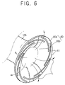
- the shroud 60 is placed between the first gas suction part 45 and the first diffuser 47, being spaced from the blade 43 of the first impeller 47. Further, the shroud 60 is formed with a plurality of channels 61 inclined toward the first diffuser 47 along a rotating direction of the impeller 40 in order to eliminate a backflow "a" and a leakage flow "b".
- the backflow "a” occurs as a gas flows from the first diffuser 47, in which pressure is relatively high, to the first gas suction part 45, in which pressure is relatively low, along the shroud 60 as a result of the pressure difference between the first diffuser 47 and the first gas suction 45.
- Such backflow interrupts a diffusing flow "c" in which the gas flows from the first gas suction part 45 to the first diffuser 47 via the first impeller 40, thereby decreasing compression efficiency.
- drawn gas on opposite sides of each blade 43 provided in the first impeller 40 have different velocities, frictional properties, etc. according to the rotating direction of the first impeller 40. Therefore, gas pressures are applied differently to the opposite sides of each blade 43.
- the pressure difference causes the leakage flow "b” (see Figure 7), in which the gas flows from a first side of the blade 43 to a second side of the blade 43 across the blade 43, to be generated through a space 65 between the shroud 60 and the blade 43.
- Such leakage flow “b” flows over the adjacent blade 43 across the diffusing flow “c” and affects the diffusing flow "c", thereby decreasing the compression efficiency.
- the plurality of channels 61 is provided on a gas discharging area 60a of the shroud 60 adjacent to the first diffuser 47 as opposed to a gas suction area 60b of the shroud 60 adjacent to the first gas suction.
- the reason why the channels 61 are provided on the gas discharging area 60a is that most of the backflow "c" and the leakage flow "b" appears on the gas discharging area 60a of the shroud 60.
- the plurality of channels 61 may be provided on the whole inside circumference surface of the shroud 60 including the gas suction area 60b as well as the gas discharging area 60a.
- the adjacent channels 61 are spaced from each other in a direction of the diffusing flow "c" and overlap each other. That is, as shown in Figure 6, the adjacent channels 61 overlap each other to effectively eliminate the backflow "a” and the leakage flow "b" at opposite ends of each channel 61.
- each channel 61 has a curved shape. That is, as shown in Figure 6, each channel 61 defines an arc with respect to the direction of the diffusing flow "c". This allows the leakage flow "b", generated in the opposite sides of the blade 43 of the first impeller 40 to the first diffuser 47 through the plurality of channels 61, to be discharged.
- each channel 61 is recessed on the inside circumference surface of the shroud 60. Further, each channel 61 has a rectangular section, but may have a semicircular section, etc. Further, each channel 61 has a width, which is wide enough to eliminate the backflow "a" and the leakage flow "b", wherein the width of the channel 61 may vary according to the size, the rotating speed, etc. of the first impeller 40.
- the first impeller 40 and the shroud 60 of the turbo compressor 1 according to the first embodiment of the present invention are operated as follows.
- the driving motor 20 is turned on and rotates the rotating shaft 5.
- the first impeller 40 is rotated integrally with the rotating shaft 5, so that the rotation of the first impeller 40 causes the gas to flow from the first gas suction part 45 to the first diffuser 47.
- the backflow "a" from the first diffuser 47 to the first gas suction part 45 due to the pressure difference between the first diffuser 47 and the first gas suction part 45 is accommodated in the plurality of channels 61, thereby eliminating the backflow "a".
- the leakage flow "b" due to the pressure difference between the opposite sides of the blade 43 of the impeller 40 is accommodated and flows toward the first diffuser 47 along a lengthwise direction of each channel 61, thereby eliminating the leakage flow "b" from flowing across the diffusing flow "c".
- the plurality of channels 61 is provided on the shroud 60 and is inclined toward the first diffuser 47 in the rotating direction of the impeller 40, and the leakage flow "b" as well as the backflow "a” are substantially eliminated.
- FIG 8 is a perspective view of a shroud provided in a turbo compressor according to a second embodiment of the present invention.
- the shroud 60 according to the second embodiment further comprises at least one auxiliary channel 63 placed between the first gas suction part 45 and the plurality of channels 61 and arranged along the rotating direction of the first impeller 40.
- the plurality of auxiliary channels 63 is annularly provided along the rotating direction of the impeller 40 in a front of the shroud 60, which is formed with the channels 61, wherein the auxiliary channels 63 are spaced from each other. That is, the auxiliary channels 63 are provided in the gas suction area 60b of the shroud 60 in front of the channels 61 provided in the gas discharging area 60a of the shroud 60. Further, the auxiliary channels 63 are recessed on the inside circumference surface of the shroud 60, having diameters different from each other concentrically on a rotating axis of the impeller 140.
- the plurality of auxiliary channels 63 are additionally provided on the shroud 60, so that the backflow is eliminated even when the backflow "a" from the first diffuser to the first gas suction part 45 flows over the channels 61.
- the channels 61 and the auxiliary channels 63 are applied to the first impeller 40 and the shroud 60 shrouding the first impeller 40, but it should be appreciated that the channels 61 and the auxiliary channels 63 are applied to the second impeller 50 and the shroud 60 shrouding the second impeller 50.
- the present invention provides a turbo compressor in which compression efficiency is increased by eliminating a backflow and a leakage flow.
Landscapes
- Engineering & Computer Science (AREA)
- Mechanical Engineering (AREA)
- General Engineering & Computer Science (AREA)
- Structures Of Non-Positive Displacement Pumps (AREA)
Applications Claiming Priority (2)
| Application Number | Priority Date | Filing Date | Title |
|---|---|---|---|
| KR2004001085 | 2004-01-08 | ||
| KR1020040001085A KR100568183B1 (ko) | 2004-01-08 | 2004-01-08 | 터보압축기 |
Publications (2)
| Publication Number | Publication Date |
|---|---|
| EP1553304A2 true EP1553304A2 (de) | 2005-07-13 |
| EP1553304A3 EP1553304A3 (de) | 2009-06-24 |
Family
ID=34588129
Family Applications (1)
| Application Number | Title | Priority Date | Filing Date |
|---|---|---|---|
| EP04253611A Withdrawn EP1553304A3 (de) | 2004-01-08 | 2004-06-17 | Kreiselverdichter |
Country Status (5)
| Country | Link |
|---|---|
| US (1) | US7338251B2 (de) |
| EP (1) | EP1553304A3 (de) |
| JP (1) | JP4168032B2 (de) |
| KR (1) | KR100568183B1 (de) |
| CN (1) | CN100363628C (de) |
Cited By (3)
| Publication number | Priority date | Publication date | Assignee | Title |
|---|---|---|---|---|
| EP2171283A4 (de) * | 2007-02-14 | 2013-01-30 | Borgwarner Inc | Verdichtergehäuse |
| EP2687684A1 (de) * | 2012-07-17 | 2014-01-22 | MTU Aero Engines GmbH | Anstreifbelag mit Spiralnuten in einer Strömungsmaschine |
| WO2016131534A1 (de) * | 2015-02-17 | 2016-08-25 | Daimler Ag | Verdichter, insbesondere für einen abgasturbolader einer verbrennungskraftmaschine |
Families Citing this family (33)
| Publication number | Priority date | Publication date | Assignee | Title |
|---|---|---|---|---|
| KR20060081791A (ko) * | 2005-01-10 | 2006-07-13 | 삼성전자주식회사 | 터보압축기를 구비한 냉동장치 |
| WO2007084100A1 (en) * | 2005-12-12 | 2007-07-26 | United Technologies Corporation | Bearing-like structure to control deflections of a rotating component |
| US8506238B2 (en) * | 2006-03-16 | 2013-08-13 | Ford Global Technologies, Llc | Water pump with housing/impeller to enhance seal performance |
| US20080044273A1 (en) * | 2006-08-15 | 2008-02-21 | Syed Arif Khalid | Turbomachine with reduced leakage penalties in pressure change and efficiency |
| US8157517B2 (en) * | 2009-04-27 | 2012-04-17 | Elliott Company | Boltless multi-part diaphragm for use with a centrifugal compressor |
| US8801364B2 (en) * | 2010-06-04 | 2014-08-12 | Honeywell International Inc. | Impeller backface shroud for use with a gas turbine engine |
| KR101279567B1 (ko) * | 2011-02-28 | 2013-06-28 | 삼성테크윈 주식회사 | 회전 기계 |
| US8727733B2 (en) * | 2011-05-26 | 2014-05-20 | General Electric Company | Gas turbine compressor last stage rotor blades with axial retention |
| CN104204453B (zh) * | 2012-04-23 | 2019-03-08 | 博格华纳公司 | 带横向凹槽的涡轮增压器护罩以及结合有该护罩的涡轮增压器 |
| CN104204444B (zh) * | 2012-04-23 | 2017-06-30 | 博格华纳公司 | 具有轮廓边缘离隙的涡轮增压器叶片和结合有该涡轮增压器叶片的涡轮增压器 |
| RU2014145610A (ru) | 2012-04-23 | 2016-06-10 | Боргварнер Инк. | Ступица турбины с несплошностью поверхности и турбонагнетатель, содержащий такую ступицу |
| KR101790421B1 (ko) * | 2013-01-23 | 2017-10-25 | 컨셉츠 이티아이 인코포레이티드 | 터보머신들의 인접한 블레이드 요소들의 흐름장들의 결합을 가하는 구조들 및 방법들, 그리고 그들을 포함하는 터보머신들 |
| CN105051372B (zh) * | 2013-01-31 | 2017-05-31 | 丹佛斯公司 | 具有扩展的操作范围的离心压缩机 |
| EP2971547B1 (de) * | 2013-03-12 | 2020-01-01 | United Technologies Corporation | Freitragender stator mit wirbelerzeugungsfunktion |
| DE102013018286A1 (de) * | 2013-10-31 | 2015-04-30 | Man Diesel & Turbo Se | Radialverdichter |
| DE102013022146A1 (de) * | 2013-12-18 | 2015-06-18 | Man Diesel & Turbo Se | Radialverdichter und Verdichteranordnung mit einem solchen Radialverdichter |
| CN104564737A (zh) * | 2014-01-13 | 2015-04-29 | 陈永刚 | 一种旋轮增压制冷压缩机 |
| US9644639B2 (en) * | 2014-01-27 | 2017-05-09 | Pratt & Whitney Canada Corp. | Shroud treatment for a centrifugal compressor |
| WO2015200533A1 (en) * | 2014-06-24 | 2015-12-30 | Concepts Eti, Inc. | Flow control structures for turbomachines and methods of designing the same |
| DE102014224757A1 (de) * | 2014-12-03 | 2016-06-09 | Robert Bosch Gmbh | Verdichter mit einem Dichtkanal |
| JP6369621B2 (ja) * | 2015-02-18 | 2018-08-08 | 株式会社Ihi | 遠心圧縮機および過給機 |
| DE102016112709A1 (de) * | 2016-07-12 | 2018-01-18 | Miele & Cie. Kg | Dichtungsvorrichtung für ein Gebläselaufrad und Gebläse |
| CN107956746A (zh) * | 2017-10-20 | 2018-04-24 | 珠海格力电器股份有限公司 | 一种用于离心风机的降噪集流器、离心风机和空调系统 |
| CN108591082A (zh) * | 2018-07-25 | 2018-09-28 | 江苏涞森环保设备有限公司 | 一种轴向推力自平衡型多级离心鼓风机 |
| EP3969761A1 (de) | 2019-05-14 | 2022-03-23 | Carrier Corporation | Zentrifugalverdichter mit diffuserdruckausgleichsfunktion |
| US11598347B2 (en) * | 2019-06-28 | 2023-03-07 | Trane International Inc. | Impeller with external blades |
| JP2023536998A (ja) | 2020-08-07 | 2023-08-30 | コンセプツ エヌアールイーシー,エルエルシー | 性能を向上させるための流量制御構造及び当該流量制御構造を組み込んだターボ機械 |
| CN116529490B (zh) * | 2020-12-03 | 2025-12-23 | 丹佛斯公司 | 包括带凹槽的扩散器的制冷剂压缩机 |
| KR102239812B1 (ko) * | 2020-12-22 | 2021-04-14 | 박배홍 | 터보 압축기 |
| CN112648226A (zh) * | 2020-12-23 | 2021-04-13 | 苏州苏磁智能科技有限公司 | 一种防气体回流的结构及包含该防气体回流的结构的磁悬浮式压缩机及透平电机系统 |
| KR102739885B1 (ko) * | 2022-01-27 | 2024-12-10 | 엘지전자 주식회사 | 터보 압축기 |
| CN115341962A (zh) * | 2022-06-29 | 2022-11-15 | 中国北方发动机研究所(天津) | 一种超临界二氧化碳闭式循环涡轮反预旋抑流结构 |
| CN116146503A (zh) * | 2023-02-23 | 2023-05-23 | 安徽美芝精密制造有限公司 | 压缩机、空调器、燃料电池模组和车辆 |
Family Cites Families (15)
| Publication number | Priority date | Publication date | Assignee | Title |
|---|---|---|---|---|
| US3893787A (en) * | 1974-03-14 | 1975-07-08 | United Aircraft Corp | Centrifugal compressor boundary layer control |
| FR2558900B1 (fr) * | 1984-02-01 | 1988-05-27 | Snecma | Dispositif d'etancheite peripherique d'aubage de compresseur axial |
| JPH06193596A (ja) | 1992-12-28 | 1994-07-12 | Hitachi Ltd | ターボ圧縮機 |
| US5350039A (en) * | 1993-02-25 | 1994-09-27 | Nartron Corporation | Low capacity centrifugal refrigeration compressor |
| CZ48394A3 (en) * | 1993-03-04 | 1994-09-14 | Abb Management Ag | Radial-flow compressor with a flow-stabilizing casing |
| JPH10141293A (ja) | 1996-11-08 | 1998-05-26 | Daikin Ind Ltd | 遠心式流体機械 |
| KR100279599B1 (ko) * | 1997-12-26 | 2001-02-01 | 구자홍 | 터보압축기 |
| KR20000003085A (ko) | 1998-06-25 | 2000-01-15 | 구자홍 | 터보 압축기의 간극누설 저감구조 |
| US6164911A (en) * | 1998-11-13 | 2000-12-26 | Pratt & Whitney Canada Corp. | Low aspect ratio compressor casing treatment |
| KR20000065622A (ko) | 1999-04-07 | 2000-11-15 | 구자홍 | 터보 압축기의 가스역류 방지구조 |
| EP1069315B1 (de) * | 1999-07-15 | 2007-09-12 | Hitachi Plant Technologies, Ltd. | Turbomaschinen |
| US6290458B1 (en) * | 1999-09-20 | 2001-09-18 | Hitachi, Ltd. | Turbo machines |
| KR100343725B1 (ko) | 2000-02-17 | 2002-07-20 | 엘지전자주식회사 | 터보 압축기의 역회전 방지장치 |
| KR100343726B1 (ko) | 2000-02-17 | 2002-07-20 | 엘지전자주식회사 | 터보 압축기의 가스누설 저감구조 |
| DE10029808C1 (de) * | 2000-06-16 | 2001-11-29 | Daimler Chrysler Ag | Abgasturbolader für eine Brennkraftmaschine |
-
2004
- 2004-01-08 KR KR1020040001085A patent/KR100568183B1/ko not_active Expired - Fee Related
- 2004-06-17 EP EP04253611A patent/EP1553304A3/de not_active Withdrawn
- 2004-06-18 CN CNB2004100593342A patent/CN100363628C/zh not_active Expired - Fee Related
-
2005
- 2005-01-06 US US11/029,424 patent/US7338251B2/en not_active Expired - Fee Related
- 2005-01-07 JP JP2005003102A patent/JP4168032B2/ja not_active Expired - Fee Related
Cited By (3)
| Publication number | Priority date | Publication date | Assignee | Title |
|---|---|---|---|---|
| EP2171283A4 (de) * | 2007-02-14 | 2013-01-30 | Borgwarner Inc | Verdichtergehäuse |
| EP2687684A1 (de) * | 2012-07-17 | 2014-01-22 | MTU Aero Engines GmbH | Anstreifbelag mit Spiralnuten in einer Strömungsmaschine |
| WO2016131534A1 (de) * | 2015-02-17 | 2016-08-25 | Daimler Ag | Verdichter, insbesondere für einen abgasturbolader einer verbrennungskraftmaschine |
Also Published As
| Publication number | Publication date |
|---|---|
| CN1637301A (zh) | 2005-07-13 |
| KR100568183B1 (ko) | 2006-04-05 |
| EP1553304A3 (de) | 2009-06-24 |
| JP4168032B2 (ja) | 2008-10-22 |
| US7338251B2 (en) | 2008-03-04 |
| CN100363628C (zh) | 2008-01-23 |
| KR20050072931A (ko) | 2005-07-13 |
| US20050152786A1 (en) | 2005-07-14 |
| JP2005195024A (ja) | 2005-07-21 |
Similar Documents
| Publication | Publication Date | Title |
|---|---|---|
| EP1553304A2 (de) | Kreiselverdichter | |
| CN104781562B (zh) | 离心旋转机械 | |
| US20230193907A1 (en) | Side-channel machine (compressor, vacuum pump or blower) having an extraction duct in the stripper | |
| EP0602007B1 (de) | Staubsauger mit Gebläserad und Diffusor | |
| WO1998003795A1 (en) | Fan wheel for an inline centrifugal fan | |
| EP1512843A3 (de) | Verfahren und Anordnung zur Kühlung von Gasturbinenrotorbauteilen | |
| US6698929B2 (en) | Turbo compressor | |
| KR102239812B1 (ko) | 터보 압축기 | |
| US10670025B2 (en) | Centrifugal compressor | |
| EP1643142A2 (de) | Folienlager und Turbokompressor | |
| US12241477B2 (en) | Multi-blade centrifugal air-sending device | |
| JP2018135836A (ja) | 遠心圧縮機 | |
| JP2017180237A (ja) | 遠心圧縮機 | |
| KR100339550B1 (ko) | 터보 압축기의 디퓨져 구조 | |
| WO2018179112A1 (ja) | コンプレッサのスクロール形状及び過給機 | |
| KR100405984B1 (ko) | 터보 압축기의 디퓨저 장착구조 | |
| KR20060080285A (ko) | 터보압축기 | |
| KR100390489B1 (ko) | 터보 압축기의 가스누설 저감구조 | |
| JP2544454B2 (ja) | タ―ボ形圧縮機 | |
| JP2000087899A (ja) | インレットガイドベーン装置の異音低減装置 | |
| KR20240071499A (ko) | 터보식 공기압축기 | |
| JP2004339999A (ja) | 多段流体機械 | |
| CA2260998C (en) | Fan wheel for an inline centrifugal fan | |
| KR100320207B1 (ko) | 터보 압축기 | |
| KR100273378B1 (ko) | 터보 압축기의 가스 압축구조 |
Legal Events
| Date | Code | Title | Description |
|---|---|---|---|
| PUAI | Public reference made under article 153(3) epc to a published international application that has entered the european phase |
Free format text: ORIGINAL CODE: 0009012 |
|
| 17P | Request for examination filed |
Effective date: 20040624 |
|
| AK | Designated contracting states |
Kind code of ref document: A2 Designated state(s): AT BE BG CH CY CZ DE DK EE ES FI FR GB GR HU IE IT LI LU MC NL PL PT RO SE SI SK TR |
|
| AX | Request for extension of the european patent |
Extension state: AL HR LT LV MK |
|
| PUAL | Search report despatched |
Free format text: ORIGINAL CODE: 0009013 |
|
| AK | Designated contracting states |
Kind code of ref document: A3 Designated state(s): AT BE BG CH CY CZ DE DK EE ES FI FR GB GR HU IE IT LI LU MC NL PL PT RO SE SI SK TR |
|
| AX | Request for extension of the european patent |
Extension state: AL HR LT LV MK |
|
| AKX | Designation fees paid | ||
| REG | Reference to a national code |
Ref country code: DE Ref legal event code: 8566 |
|
| STAA | Information on the status of an ep patent application or granted ep patent |
Free format text: STATUS: THE APPLICATION IS DEEMED TO BE WITHDRAWN |
|
| 18D | Application deemed to be withdrawn |
Effective date: 20091229 |