EP1643142A2 - Folienlager und Turbokompressor - Google Patents
Folienlager und Turbokompressor Download PDFInfo
- Publication number
- EP1643142A2 EP1643142A2 EP05103253A EP05103253A EP1643142A2 EP 1643142 A2 EP1643142 A2 EP 1643142A2 EP 05103253 A EP05103253 A EP 05103253A EP 05103253 A EP05103253 A EP 05103253A EP 1643142 A2 EP1643142 A2 EP 1643142A2
- Authority
- EP
- European Patent Office
- Prior art keywords
- foils
- bearing
- elastic
- base
- curvature
- Prior art date
- Legal status (The legal status is an assumption and is not a legal conclusion. Google has not performed a legal analysis and makes no representation as to the accuracy of the status listed.)
- Granted
Links
Images


Classifications
-
- F—MECHANICAL ENGINEERING; LIGHTING; HEATING; WEAPONS; BLASTING
- F04—POSITIVE - DISPLACEMENT MACHINES FOR LIQUIDS; PUMPS FOR LIQUIDS OR ELASTIC FLUIDS
- F04D—NON-POSITIVE-DISPLACEMENT PUMPS
- F04D29/00—Details, component parts, or accessories
- F04D29/04—Shafts or bearings, or assemblies thereof
-
- F—MECHANICAL ENGINEERING; LIGHTING; HEATING; WEAPONS; BLASTING
- F16—ENGINEERING ELEMENTS AND UNITS; GENERAL MEASURES FOR PRODUCING AND MAINTAINING EFFECTIVE FUNCTIONING OF MACHINES OR INSTALLATIONS; THERMAL INSULATION IN GENERAL
- F16C—SHAFTS; FLEXIBLE SHAFTS; ELEMENTS OR CRANKSHAFT MECHANISMS; ROTARY BODIES OTHER THAN GEARING ELEMENTS; BEARINGS
- F16C17/00—Sliding-contact bearings for exclusively rotary movement
- F16C17/04—Sliding-contact bearings for exclusively rotary movement for axial load only
- F16C17/042—Sliding-contact bearings for exclusively rotary movement for axial load only with flexible leaves to create hydrodynamic wedge, e.g. axial foil bearings
-
- F—MECHANICAL ENGINEERING; LIGHTING; HEATING; WEAPONS; BLASTING
- F04—POSITIVE - DISPLACEMENT MACHINES FOR LIQUIDS; PUMPS FOR LIQUIDS OR ELASTIC FLUIDS
- F04D—NON-POSITIVE-DISPLACEMENT PUMPS
- F04D29/00—Details, component parts, or accessories
- F04D29/05—Shafts or bearings, or assemblies thereof, specially adapted for elastic fluid pumps
- F04D29/051—Axial thrust balancing
- F04D29/0513—Axial thrust balancing hydrostatic; hydrodynamic thrust bearings
-
- F—MECHANICAL ENGINEERING; LIGHTING; HEATING; WEAPONS; BLASTING
- F16—ENGINEERING ELEMENTS AND UNITS; GENERAL MEASURES FOR PRODUCING AND MAINTAINING EFFECTIVE FUNCTIONING OF MACHINES OR INSTALLATIONS; THERMAL INSULATION IN GENERAL
- F16C—SHAFTS; FLEXIBLE SHAFTS; ELEMENTS OR CRANKSHAFT MECHANISMS; ROTARY BODIES OTHER THAN GEARING ELEMENTS; BEARINGS
- F16C2360/00—Engines or pumps
- F16C2360/44—Centrifugal pumps
Definitions
- the present invention relates to a bearing comprising a plurality of elastic foils, in particular a bearing for use in a turbo compressor.
- Turbo compressors are used to compress gas, such as air or a refrigerant gas.
- gas such as air or a refrigerant gas.
- an impeller is rotated due to the driving force of a motor to generate a centrifugal force to intake and compress the gas.
- the turbo compressor is provided with radial bearings and thrust bearings to support the rotational shaft according to the direction of a load applied to the shaft.
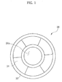
- a conventional thrust bearing 30 has a configuration wherein several elastic foils 31 overlap each other on one side of a disc-shaped base 33 having an opening 30a formed at the centre thereof so that the elastic foils 31 contact a disc (not shown) attached to a rotational shaft (not shown).
- a gaseous film is subsequently formed between the disc and the elastic foils 31 such that the disc is spaced a predetermined distance from the elastic foils 31.
- the present invention seeks to provide a bearing which overcomes or substantially alleviates the problems discussed above and in which a bearing for use in a turbo compressor enhances the load capacity of a disc and prevents damage to a surface of a plurality of elastic foils of the bearing and the mechanical malfunction of the turbo compressor.
- a bearing according to the present invention comprises a plurality of elastic foils having different stiffness values from each other.
- the elastic foils have different radii of curvature from each other.
- the elastic foils are arranged circumferentially on one side of a disc-shaped base.
- the elastic foils comprise inner foils circumferentially arranged on an inner portion of the base and outer foils circumferentially arranged on an outer portion of the base.
- the inner foils have a lower stiffness and a higher radius of curvature than the outer foils.
- Each of the elastic foils may have one end supported by the base and the other end placed on an adjacent elastic foil.
- the end of the foil supported by the base is fixed to the base via a supporting member.
- a bearing according to the present invention comprises a plurality of elastic foils having different radii of curvature from each other.
- a turbo compressor including a bearing according to the present invention comprises a plurality of elastic foils having different stiffness values from each other.
- FIG. 2 a turbo compressor comprising a housing 10 with a driving chamber 8 formed therein.
- a rotational shaft 1 Across the driving chamber 8 is located a rotational shaft 1.
- a rotator 5 is positioned around the centre of the rotational shaft 1 and a stator 3 is located at an outer portion of the rotator 5 corresponding to a location of the rotator 5 within a wall of the driving chamber 8.
- a driving motor 7 comprising the stator 3 and the rotator 5 forces rotation of the rotational shaft by virtue of electromagnetic cooperation of the stator 3 and the rotator 5 when electric power is applied from a power supply to the driving motor 7.
- Radial bearings 9 and thrust bearings 20 support the rotational shaft 1 within the driving chamber 8.
- the thrust bearings 20 are located on both sides of a disc 1a provided around an outer periphery of the rotational shaft 1 such that they contact the disc 1a thereby supporting the rotational shaft 1 in an axial direction of the rotational shaft 1.
- the rotational shaft 1 is provided with impellers 4a and 4b fixed to both ends of the rotational shaft 1.
- a first stage impeller 4a is provided to an intake port of the housing 10 and a second stage impeller 4b is provided to a discharge port of the housing 10.
- the housing 10 is formed with an intake pipe 6a which communicates with the outside of the housing in order to allow a refrigerant to be supplied to the first stage impeller 4a and with a discharge pipe 6c which communicates with the outside in order to allow a compressed refrigerant to be discharged from the second stage impeller 4b to the outside.
- the first stage impeller 4a communicates with the second stage impeller 4b via a connecting pipe 6b.
- the first stage impeller 4a and the second stage impeller 4b are also rotated.
- the refrigerant, having flowed into the housing 10 through the intake pipe 6a by virtue of rotation of the first stage impeller 4a, is primarily compressed by the first stage impeller 4a and is then supplied to the second stage impeller 4b through the connecting pipe 6b.
- the second stage impeller 4b secondarily compresses the primarily compressed refrigerant and discharges secondarily compressed refrigerant to the discharge pipe 6c.
- the housing 10 is formed with a cooling refrigerant intake port 8a and a cooling refrigerant discharge port 8b which communicate with the driving chamber 8. That is, the interior of the driving chamber 8 is cooled by forcing a portion of the refrigerant circulating within a refrigerant cycle to flow to the driving chamber 8 through the cooling refrigerant intake port 8a and to return to the refrigerant cycle through the cooling refrigerant discharge port 8b.
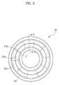
- the bearing 20 has a disc-shaped base 23 with an opening 23a formed at the centre of the base 23 and a plurality of elastic foils 22a and 22b attached to one side of the base 23.
- the elastic foils 22a and 22b comprise inner foils 22a attached to an inner portion of the base 23 and outer foils 22b attached to an outer portion of the base 23.
- the elastic foils 22a and 22b are circumferentially arranged on the one side of the base such that the inner foils 22a overlap each other and the outer foils 22b overlap each other.
- each of the elastic foils 22a and 22b has one end fixed to the base 23 via a supporting member 25 and the other end positioned on an upper portion of the other adjacent elastic foil respectively.
- the inner foils 22a have a radius of curvature higher than that of the outer foils 22b and have a separation from the base 23 higher than that of the outer foils 22b.
- the inner foils 22a have a relatively low stiffness compared with that of the outer foils 22b.
- gaseous films having a predetermined space are formed between the disc 1a and the inner foils 22a and between the disc 1a and the outer foils 22b so that the inner foils 22a and the outer foils 22b are separated from the disc 1a.
- the disc 1a is simultaneously supported by the inner foils 22a and the outer foils 22b so that the load is dispersed to the inner foils 22a and the outer foils 22b thereby increasing the load capacity of the disc 1a.
Landscapes
- Engineering & Computer Science (AREA)
- General Engineering & Computer Science (AREA)
- Mechanical Engineering (AREA)
- Physics & Mathematics (AREA)
- Fluid Mechanics (AREA)
- Structures Of Non-Positive Displacement Pumps (AREA)
- Support Of The Bearing (AREA)
Applications Claiming Priority (1)
| Application Number | Priority Date | Filing Date | Title |
|---|---|---|---|
| KR1020040063930A KR20060015094A (ko) | 2004-08-13 | 2004-08-13 | 베어링 및 이를 포함하는 터보압축기 |
Publications (3)
| Publication Number | Publication Date |
|---|---|
| EP1643142A2 true EP1643142A2 (de) | 2006-04-05 |
| EP1643142A3 EP1643142A3 (de) | 2007-09-19 |
| EP1643142B1 EP1643142B1 (de) | 2010-08-18 |
Family
ID=35266895
Family Applications (1)
| Application Number | Title | Priority Date | Filing Date |
|---|---|---|---|
| EP05103253A Expired - Lifetime EP1643142B1 (de) | 2004-08-13 | 2005-04-21 | Folienlager und Turbokompressor |
Country Status (5)
| Country | Link |
|---|---|
| US (1) | US7364363B2 (de) |
| EP (1) | EP1643142B1 (de) |
| JP (1) | JP2006052837A (de) |
| KR (1) | KR20060015094A (de) |
| DE (1) | DE602005022965D1 (de) |
Families Citing this family (15)
| Publication number | Priority date | Publication date | Assignee | Title |
|---|---|---|---|---|
| US7374342B2 (en) * | 2004-07-26 | 2008-05-20 | Samsung Techwin Co., Ltd. | Hydrodynamic fluid film bearing and bearing housing with cooling capacity |
| JP5174074B2 (ja) * | 2010-03-25 | 2013-04-03 | 本田技研工業株式会社 | 電動遠心圧縮機 |
| JP2011202588A (ja) * | 2010-03-25 | 2011-10-13 | Honda Motor Co Ltd | 遠心型圧縮機 |
| DE102011077771A1 (de) * | 2011-06-17 | 2012-12-20 | Bosch Mahle Turbo Systems Gmbh & Co. Kg | Axiallageranordnung |
| EP2740951B1 (de) * | 2011-08-01 | 2018-09-12 | NTN Corporation | Druckfolienlager |
| WO2015087677A1 (ja) * | 2013-12-12 | 2015-06-18 | Ntn株式会社 | スラストフォイル軸受、ラジアルフォイル軸受、及びこれらの製造方法 |
| CN104896037A (zh) * | 2015-06-04 | 2015-09-09 | 湖南猎豹汽车股份有限公司 | 一种双向传递扭矩的锁止环、离合器及应用的两档自动变速器 |
| JP6615573B2 (ja) * | 2015-10-28 | 2019-12-04 | Ntn株式会社 | スラストフォイル軸受 |
| WO2018047840A1 (ja) * | 2016-09-07 | 2018-03-15 | Ntn株式会社 | フォイル軸受 |
| KR102659634B1 (ko) * | 2018-09-21 | 2024-04-23 | 한화파워시스템 주식회사 | 가스 포일 베어링 및 이를 포함하는 유체 기계 |
| JPWO2020130124A1 (ja) * | 2018-12-20 | 2021-09-30 | 株式会社Ihi | スラストフォイル軸受 |
| JP2020139607A (ja) * | 2019-03-01 | 2020-09-03 | Ntn株式会社 | スラストフォイル軸受 |
| KR102283021B1 (ko) * | 2019-03-15 | 2021-07-28 | 엘지전자 주식회사 | 터보 압축기용 스러스트 베어링 |
| KR102413773B1 (ko) * | 2020-05-26 | 2022-06-29 | 주식회사 뉴로스 | 에어 포일 스러스트 베어링 |
| DE102023210860A1 (de) * | 2023-11-02 | 2025-05-08 | Robert Bosch Gesellschaft mit beschränkter Haftung | Lageranordnung eines elektrisch angetriebenen Verdichters |
Citations (3)
| Publication number | Priority date | Publication date | Assignee | Title |
|---|---|---|---|---|
| US5871284A (en) | 1997-09-10 | 1999-02-16 | Alliedsignal Inc. | Foil thrust bearing set |
| KR20020066409A (ko) | 2001-02-10 | 2002-08-17 | 엘지전자주식회사 | 터보 압축기의 트러스트 베어링 |
| EP1270971A1 (de) | 1997-04-03 | 2003-01-02 | Samsung Aerospace Industries, Ltd. | Dynamisches Gaslager mit Folien |
Family Cites Families (17)
| Publication number | Priority date | Publication date | Assignee | Title |
|---|---|---|---|---|
| US4482303A (en) * | 1982-01-27 | 1984-11-13 | Ray Acosta | Turbo-compressor apparatus |
| US4549821A (en) * | 1982-11-17 | 1985-10-29 | Aisin Seiki Kabushiki Kaisha | Foil bearing |
| US5110220A (en) | 1991-03-08 | 1992-05-05 | Allied-Signal Inc. | Thrust bearing underspring |
| US5634723A (en) * | 1995-06-15 | 1997-06-03 | R & D Dynamics Corporation | Hydrodynamic fluid film bearing |
| US5833369A (en) * | 1997-03-28 | 1998-11-10 | Mohawk Innovative Technology, Inc. | High load capacity compliant foil hydrodynamic thrust bearing |
| US5902049A (en) * | 1997-03-28 | 1999-05-11 | Mohawk Innovative Technology, Inc. | High load capacity compliant foil hydrodynamic journal bearing |
| KR100273374B1 (ko) | 1997-12-26 | 2001-01-15 | 구자홍 | 터보압축기의 스러스트 베어링 구조 |
| KR100273376B1 (ko) | 1997-12-26 | 2001-01-15 | 구자홍 | 터보압축기 |
| KR100253247B1 (ko) | 1998-01-20 | 2000-05-01 | 구자홍 | 터보압축기의 스러스트 베어링 구조 |
| KR20000008563A (ko) | 1998-07-14 | 2000-02-07 | 구자홍 | 터보 압축기의 스러스트 베어링 구조 |
| KR100304563B1 (ko) | 1998-07-23 | 2001-12-20 | 구자홍 | 터보압축기 |
| KR100585587B1 (ko) | 1999-02-22 | 2006-06-07 | 삼성테크윈 주식회사 | 에어포일베어링 |
| KR20000065623A (ko) | 1999-04-07 | 2000-11-15 | 구자홍 | 터보 압축기의 스러스트 베어링 구조 |
| KR100320193B1 (ko) | 1999-06-02 | 2002-01-10 | 구자홍 | 터보 압축기의 가스베어링 냉각구조 |
| KR100339545B1 (ko) | 1999-07-09 | 2002-06-03 | 구자홍 | 터보 압축기 |
| KR100379497B1 (ko) | 2000-10-17 | 2003-04-10 | 엘지전자 주식회사 | 터보 압축기의 구동축 |
| KR100414110B1 (ko) | 2001-09-25 | 2004-01-07 | 엘지전자 주식회사 | 터보 압축기의 베어링 냉각구조 |
-
2004
- 2004-08-13 KR KR1020040063930A patent/KR20060015094A/ko not_active Withdrawn
-
2005
- 2005-04-21 EP EP05103253A patent/EP1643142B1/de not_active Expired - Lifetime
- 2005-04-21 DE DE602005022965T patent/DE602005022965D1/de not_active Expired - Lifetime
- 2005-05-13 US US11/128,341 patent/US7364363B2/en not_active Expired - Fee Related
- 2005-06-01 JP JP2005161283A patent/JP2006052837A/ja active Pending
Patent Citations (3)
| Publication number | Priority date | Publication date | Assignee | Title |
|---|---|---|---|---|
| EP1270971A1 (de) | 1997-04-03 | 2003-01-02 | Samsung Aerospace Industries, Ltd. | Dynamisches Gaslager mit Folien |
| US5871284A (en) | 1997-09-10 | 1999-02-16 | Alliedsignal Inc. | Foil thrust bearing set |
| KR20020066409A (ko) | 2001-02-10 | 2002-08-17 | 엘지전자주식회사 | 터보 압축기의 트러스트 베어링 |
Also Published As
| Publication number | Publication date |
|---|---|
| JP2006052837A (ja) | 2006-02-23 |
| DE602005022965D1 (de) | 2010-09-30 |
| EP1643142A3 (de) | 2007-09-19 |
| EP1643142B1 (de) | 2010-08-18 |
| KR20060015094A (ko) | 2006-02-16 |
| US20060045396A1 (en) | 2006-03-02 |
| US7364363B2 (en) | 2008-04-29 |
Similar Documents
| Publication | Publication Date | Title |
|---|---|---|
| EP1643142B1 (de) | Folienlager und Turbokompressor | |
| US7338251B2 (en) | Turbo compressor | |
| EP3401549B1 (de) | Turboverdichter | |
| US20150267717A1 (en) | Turbo type fluid machine | |
| KR101004701B1 (ko) | 원심압축기 | |
| US6698929B2 (en) | Turbo compressor | |
| US11885347B2 (en) | Centrifugal compressor | |
| CN116897251A (zh) | 包括分段式内箔组件的箔轴承组件和包括该轴承组件的压缩机 | |
| US5927940A (en) | Double-flow gas friction pump | |
| KR102811284B1 (ko) | 에어포일 스러스트 베어링 및 하우징 조립체, 이를 포함하는 차량용 공기 압축기 | |
| KR100343712B1 (ko) | 터보 압축기의 안전장치 | |
| JP2002332990A (ja) | ターボ形回転機器 | |
| JP3879174B2 (ja) | 圧縮機 | |
| JP2003139086A (ja) | 超薄型ポンプ | |
| JP2006152994A (ja) | 遠心圧縮機 | |
| KR100399325B1 (ko) | 터보 압축기의 트러스트 베어링 | |
| KR101091890B1 (ko) | 터보 압축기 | |
| KR100343709B1 (ko) | 터보 압축기의 회전축 조립체 | |
| KR101113831B1 (ko) | 터보 기기 | |
| KR20030029231A (ko) | 터보 압축기의 축 베어링 방열구조 | |
| KR100339545B1 (ko) | 터보 압축기 | |
| KR20060080285A (ko) | 터보압축기 | |
| KR20240162152A (ko) | 포일 베어링 및 유체 기계 | |
| WO2001027477A1 (en) | Water pump (circulation pump) using no retainer | |
| KR20210085934A (ko) | 추력 감소 기능을 갖는 압축기 및 이를 갖는 터보 냉동기 |
Legal Events
| Date | Code | Title | Description |
|---|---|---|---|
| PUAI | Public reference made under article 153(3) epc to a published international application that has entered the european phase |
Free format text: ORIGINAL CODE: 0009012 |
|
| AK | Designated contracting states |
Kind code of ref document: A2 Designated state(s): AT BE BG CH CY CZ DE DK EE ES FI FR GB GR HU IE IS IT LI LT LU MC NL PL PT RO SE SI SK TR |
|
| AX | Request for extension of the european patent |
Extension state: AL BA HR LV MK YU |
|
| PUAL | Search report despatched |
Free format text: ORIGINAL CODE: 0009013 |
|
| AK | Designated contracting states |
Kind code of ref document: A3 Designated state(s): AT BE BG CH CY CZ DE DK EE ES FI FR GB GR HU IE IS IT LI LT LU MC NL PL PT RO SE SI SK TR |
|
| AX | Request for extension of the european patent |
Extension state: AL BA HR LV MK YU |
|
| 17P | Request for examination filed |
Effective date: 20080205 |
|
| 17Q | First examination report despatched |
Effective date: 20080312 |
|
| AKX | Designation fees paid |
Designated state(s): DE FR GB |
|
| GRAP | Despatch of communication of intention to grant a patent |
Free format text: ORIGINAL CODE: EPIDOSNIGR1 |
|
| GRAS | Grant fee paid |
Free format text: ORIGINAL CODE: EPIDOSNIGR3 |
|
| GRAA | (expected) grant |
Free format text: ORIGINAL CODE: 0009210 |
|
| AK | Designated contracting states |
Kind code of ref document: B1 Designated state(s): DE FR GB |
|
| REG | Reference to a national code |
Ref country code: GB Ref legal event code: FG4D |
|
| REF | Corresponds to: |
Ref document number: 602005022965 Country of ref document: DE Date of ref document: 20100930 Kind code of ref document: P |
|
| PLBE | No opposition filed within time limit |
Free format text: ORIGINAL CODE: 0009261 |
|
| STAA | Information on the status of an ep patent application or granted ep patent |
Free format text: STATUS: NO OPPOSITION FILED WITHIN TIME LIMIT |
|
| 26N | No opposition filed |
Effective date: 20110519 |
|
| REG | Reference to a national code |
Ref country code: DE Ref legal event code: R097 Ref document number: 602005022965 Country of ref document: DE Effective date: 20110519 |
|
| REG | Reference to a national code |
Ref country code: FR Ref legal event code: PLFP Year of fee payment: 11 |
|
| PGFP | Annual fee paid to national office [announced via postgrant information from national office to epo] |
Ref country code: GB Payment date: 20150410 Year of fee payment: 11 Ref country code: DE Payment date: 20150409 Year of fee payment: 11 |
|
| PGFP | Annual fee paid to national office [announced via postgrant information from national office to epo] |
Ref country code: FR Payment date: 20150413 Year of fee payment: 11 |
|
| REG | Reference to a national code |
Ref country code: DE Ref legal event code: R119 Ref document number: 602005022965 Country of ref document: DE |
|
| GBPC | Gb: european patent ceased through non-payment of renewal fee |
Effective date: 20160421 |
|
| REG | Reference to a national code |
Ref country code: FR Ref legal event code: ST Effective date: 20161230 |
|
| PG25 | Lapsed in a contracting state [announced via postgrant information from national office to epo] |
Ref country code: FR Free format text: LAPSE BECAUSE OF NON-PAYMENT OF DUE FEES Effective date: 20160502 Ref country code: DE Free format text: LAPSE BECAUSE OF NON-PAYMENT OF DUE FEES Effective date: 20161101 Ref country code: GB Free format text: LAPSE BECAUSE OF NON-PAYMENT OF DUE FEES Effective date: 20160421 |