EP1553257A2 - Armoured door or window with glazing directly fixed to the armour plate - Google Patents
Armoured door or window with glazing directly fixed to the armour plate Download PDFInfo
- Publication number
- EP1553257A2 EP1553257A2 EP05290066A EP05290066A EP1553257A2 EP 1553257 A2 EP1553257 A2 EP 1553257A2 EP 05290066 A EP05290066 A EP 05290066A EP 05290066 A EP05290066 A EP 05290066A EP 1553257 A2 EP1553257 A2 EP 1553257A2
- Authority
- EP
- European Patent Office
- Prior art keywords
- glazing
- panel
- profile
- opening
- edge
- Prior art date
- Legal status (The legal status is an assumption and is not a legal conclusion. Google has not performed a legal analysis and makes no representation as to the accuracy of the status listed.)
- Granted
Links
Images

Classifications
-
- E—FIXED CONSTRUCTIONS
- E06—DOORS, WINDOWS, SHUTTERS, OR ROLLER BLINDS IN GENERAL; LADDERS
- E06B—FIXED OR MOVABLE CLOSURES FOR OPENINGS IN BUILDINGS, VEHICLES, FENCES OR LIKE ENCLOSURES IN GENERAL, e.g. DOORS, WINDOWS, BLINDS, GATES
- E06B5/00—Doors, windows, or like closures for special purposes; Border constructions therefor
- E06B5/10—Doors, windows, or like closures for special purposes; Border constructions therefor for protection against air-raid or other war-like action; for other protective purposes
-
- E—FIXED CONSTRUCTIONS
- E06—DOORS, WINDOWS, SHUTTERS, OR ROLLER BLINDS IN GENERAL; LADDERS
- E06B—FIXED OR MOVABLE CLOSURES FOR OPENINGS IN BUILDINGS, VEHICLES, FENCES OR LIKE ENCLOSURES IN GENERAL, e.g. DOORS, WINDOWS, BLINDS, GATES
- E06B3/00—Window sashes, door leaves, or like elements for closing wall or like openings; Layout of fixed or moving closures, e.g. windows in wall or like openings; Features of rigidly-mounted outer frames relating to the mounting of wing frames
- E06B3/54—Fixing of glass panes or like plates
- E06B3/58—Fixing of glass panes or like plates by means of borders, cleats, or the like
- E06B3/5892—Fixing of window panes in openings in door leaves
-
- E—FIXED CONSTRUCTIONS
- E06—DOORS, WINDOWS, SHUTTERS, OR ROLLER BLINDS IN GENERAL; LADDERS
- E06B—FIXED OR MOVABLE CLOSURES FOR OPENINGS IN BUILDINGS, VEHICLES, FENCES OR LIKE ENCLOSURES IN GENERAL, e.g. DOORS, WINDOWS, BLINDS, GATES
- E06B5/00—Doors, windows, or like closures for special purposes; Border constructions therefor
- E06B5/10—Doors, windows, or like closures for special purposes; Border constructions therefor for protection against air-raid or other war-like action; for other protective purposes
- E06B5/11—Doors, windows, or like closures for special purposes; Border constructions therefor for protection against air-raid or other war-like action; for other protective purposes against burglary
- E06B5/116—Arrangements preventing the removal of glazing panels
Definitions
- the invention generally relates to joinery, and including armored doors and windows.
- the invention relates to a carpentry, including a door, including a panel equipped with a shielding plate, a cut-out opening in the panel, a glazing arranged in the opening, and means for fixing the glazing on the panel.
- the means of Glazing attachment typically include moldings outer 43 and inner 44 surrounding the glazing 30 on both sides of the panel 10, these moldings covering the gap separating the edges of the panel defining the opening and sides of the glazing.
- joineries have the defect of being little resistant to break-in, even if the glazing is shielded.
- the outer molding 43 tilts and unhooks, such so that the assembly constituted by the glazing 30, the two moldings 43 and 44, and the fixing screws 45 are detaches from the panel 10 and falls on an inner side of this one.
- the moldings are generally made of aluminum, and thus offer a low intrinsic resistance to burglary.
- the molding outer 43 can be cut. We can then introduce a tool between the panel and the glazing and to bring down the latter.
- the present invention aims to to overcome the defects mentioned above.
- the device of the invention for otherwise consistent with the generic definition given in the preamble above is essentially characterized in that the fixing means comprise means to mechanically link the glazing directly to the armor plate.
- the armor plate comprises a portion of protruding into the opening from one edge of the panel, the glazing being bonded to said projecting portion.
- the protruding part of the armor plate extends the along at least part of the periphery of opening and defines a free section in the opening relatively smaller than the glazing.
- the means for mechanically binding the glazing directly to the armor plate comprise at least one metal profile capable of transmit a significant effort of glazing to the plate of shielding.
- the metal section is a profile U-shaped including a longitudinal core, a wing standing along a first transverse side of the soul, and brackets of the profile on the part protruding armor plate rising from a second transverse side of the soul opposite to the first, a side of the glazing being engaged in the profile between the wing and the legs.
- the protruding part of the plate includes fixing holes in which are engaged the legs of the profile, so that the side of the glazing is caught between the protruding part and the wing of the profile.
- the legs of the profile are shaped such that the profile is movable by pivoting around the legs between a tilted position relatively closer to the edge of the panel in which the glazing can be put in place against the part protruding, and a holding position of the glazing relatively farther from the edge of the panel.
- the soul of the profile extends substantially perpendicular to the protruding part of the armor plate, the wing and the legs of the profile being turned on a side opposite the edge of the panel.
- the fastening means comprise a clip engaged between the edge of the panel and the profile and blocking this one in his holding position.
- the glazing can be put in place against the next salient part a movement substantially perpendicular to this part protruding.
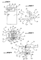
- Figure 1 shows a carpentry, in the occurrence an armored door, comprising a panel 10, an opening 20 cut in the panel 10, a glazing 30 disposed in the opening 20, and fixing means 40 of the glazing 30 on the panel 10, these means being represented in FIGS. 2 to 8.
- the panel 10 defines the general shape of the door and extends in a vertical and horizontal plane. he has a multilayer structure constituted, starting from one side of the door to one side interior, an outer decorative layer 11, a shielding plate 12, with a layer of insulating foam 13, and an interior decorative layer 14.
- the layer of insulating foam 13 is relatively thick to other layers.
- the opening 20 is cut in a part central panel 10 and has a closed contour.
- the opening 20 is rectangular and is delimited by two opposite vertical edges 15 and two horizontal edges opposite 16 of the panel 10.
- the glazing 30 comprises, starting from one side outside the glazing to go to an inner side, an outer pane 31, a vacuum 32, and an anti-burglary pane 33 separated from the outer pane 31 by the vacuum 32.
- the glazing 30 further comprises a seal 34 extending along the entire periphery of the glazing, and disposed in the vacuum 32, between the outer pane 31 and the shielded glass 33. This seal 34 provides the connection between the two panes, and isolates the vacuum 32 from outside.
- the glazing 30 has a rectangular shape, slightly smaller than that of opening 20 and substantially closes this opening 20.
- the glazing 30 has a relatively lower thickness than the panel 10.
- the fastening means 40 include means for mechanically bonding the glazing 30 directly to the armor plate 12.
- the armor plate 12 comprises a part 121 projecting into the opening 20 from the edges of the panel 10, the glazing 30 being mechanically linked to said projecting portion 121.
- the projecting portion 121 of the armor plate 12 extends in the same plane as this armor plate, along at least part of the periphery of the opening 20, and at least along two opposite edges of the panel 10, vertical 15 or horizontal 16.
- this projecting portion 121 extends along the vertical and horizontal edges 16, of continuous way around the entire opening 20.
- the projecting portion 121 extends from the edges vertical 15 and / or horizontal 16 respectively horizontally and vertically, over a width relatively larger than that in gap 37, and extends beyond gap 37, next to the sides glazing 30.
- This protruding part 121 therefore leaves a section free in the opening 20 relatively smaller than the glazing 30. This free section is completely closed by the glazing 30.
- the means to link mechanically the glazing 30 directly to the plate of shielding 12 comprise a metal section 41 adapted to transmit a significant effort of the glazing 30 to the plate shielding 12.
- This metal section 41 extends parallel to the vertical edge 15, practically the entire length of this one.
- this metal profile 41 is a U-shaped profile, comprising a longitudinal core 411 flat, a thin wing 412 standing along a first transverse side of the core 411, and legs of fixing 413 of the profile 41 on the projecting portion 121 of armor plate 12 standing on a second side transverse of the soul 411 opposite the first.
- the projecting portion 121 of the plate 12 comprises fastening holes 122 aligned vertically, in which are engaged the tabs 413 of the profile 41.
- the profile 41 is disposed on a rear side of the protruding part 121, so that the legs, after passing through the orifices 122 come out of a front side of it.
- the legs 413 of the section 41 are shaped such that the profile 41 is movable relative to the projecting portion, by pivoting around the legs 413, between a position tilted relatively closer to the vertical edge 15 of the panel 10 in which the glazing 30 can be set place against the protruding part 121, and a position of keeping the glazing 30 relatively further from the edge vertical 15 of the panel 10.
- the tabs 413 are bent, and comprise each a first rectangular pan 414 integral with the transverse edge of the soul 411 and extending in the same plan as this one, and a second rectangular pan 415 extending the first one from an opposite side to the soul 411 in a direction perpendicular to it.
- the part angle between the two faces is slightly curved.
- the orifices 122 are rectangular, elongated parallel to the vertical edge 15, and arranged at a distance of this edge 15. They have dimensions slightly higher than those in the first panel 414 section, this section being taken in a plane parallel to second pan 415.
- the soul 411 extends substantially perpendicular to the portion protruding 121 of the armor plate 12, the wing 412 and the tabs 413 of the section 41 being turned on one side opposite the vertical edge 15 of the panel 10, towards the glazing 30.
- the second panels 415 of the tabs 413 are plated against an outer side of the projection 121, the wing 412 extending substantially parallel to this protruding part, away from it on the side inside.
- a vertical side 35 of the glazing 30 is engaged in the profile 41, between the wing 412 and the legs 413, and more precisely between the wing 412 and the inner side of the protruding part 121.
- the spacing between the wing 412 and the legs 413 is chosen in such a way that the wing 412 and the side inside the projecting portion 121 are plated respectively on the burglar-proof glass 33 and on the outer pane 31.
- FIG. 4 shows the profile 41 in position tilted.
- the soul 411 extends obliquely to from the inner side of the projection 121, to the vertical edge 15.
- the first sections 414 are engaged each obliquely in the corresponding orifice 122, and the second pan 415 also extend obliquely by relative to the protrusion 121, of an outer side of it.
- the wing 414 then extends in the immediate vicinity of the vertical edge 15, or even against it.
- the glazing 30 in tilted position of the profile 41, can be put in position in the opening 20, against the projecting portion 121, following a movement substantially perpendicular to this projecting part 121.
- the glazing 30 first disposed on an inner side of the panel 10, facing the opening 20, and maintained parallel to this opening.
- orifices 122 then extend along the vertical and / or horizontal sides 16 of the glazed 30, right next to them but very slightly offset to the edge of the panel.
- the inclination of the profiles 41 is such that neither the soul 411 nor the wing 412 interferes with the trajectory glazing 30 when it is put in place.
- the soul 411 comes to press against the edge of the glazing 30, the wing 412 against the burglar-resistant glass 33, and the second sections 415 of the legs 413 against the side outside the projecting portion 121.
- the glazing 30 is perfectly maintained according to a direction perpendicular to the opening 20, since two of its opposite edges at least are imprisoned in profiles 41.
- the fastening means 40 further comprise a clip 42 engaged between the vertical edge 15 of the panel 10 and the profile 41 and blocking it in its position of maintaining, an inner molding 44 secured to the clip 42, and an outer molding 43 integral with the part protruding 121 of the armor plate 12.
- the clip 42 is made of plastic and extends the along the entire vertical edge 15 of the panel 10. It comprises a longitudinal plate 421 bearing on the soul 411 of the profile 41, and longitudinal ribs 422 integral with the plate 421 and resting on the edge vertical 15.
- the plate 421 is substantially rectangular, elongated in the vertical direction, and extends into a plane perpendicular to the protruding part 121. It presents a first large face turned on the side of the glazing 30 and plated on the core 411. The ribs longitudinal projections protrude from a large second face of the plate 421 opposite to the first, and extend mutually parallel to the layer of foam 13.
- the outer and inner moldings 43 and 44 are aluminum profiles extending around the whole glazing 30 to hide the gap 37 between this glazing and the edges of the panel 10.
- the plate 421 of the clip bears on a lateral edge of his first big face opposite the protruding part fastening studs 423 immovably engaged in the inner molding 44.
- the inner molding 44 and clip 42 are mounted together on the door, after installation of glazing 30 and metal profiles 41.
- the inner molding 44 and the clip 42 are arranged facing the opening 20, an inner side of the door, the clip 20 pointing to the glazing 30. Then they are moved to the glazing 30, following a movement perpendicular to this glazing 30, until the part outside of the clip come into the interstice 37, between the side of the glazing and the edge of the panel.
- the ribs 422 are inclined towards inside from plate 421. They allow thus the insertion of clip 42, but oppose the extraction of the clip 42 out of the gap 37.
- the length of the ribs 422 is chosen so that that they rest on the foam layer 13, with enough pressure to create a slight concavity in the foam, taking advantage of the natural elasticity of this foam.
- the outer molding 43 is screwed on the part protruding 121 of the armor plate 12.
- the projecting portion 121 is pierced with conical holes 123 arranged beside the fastening holes 122, screws 124 being engaged in these holes and coming to lodge in threaded holes in the outer molding 43.
- the 124 screw heads are entirely contained in these tapered holes 123.
- the side of the glazing 30 comes to bear on the projection 121 above the conical holes 123, blocking the heads of the screws 124 in these holes.
- the outer molding 43 includes a recess 431 into which the openings of 122. This recess is of sufficient size to allow the movement of the legs 413 of the profile 41 when tilting said profile.
- the outer and inner moldings 43 and 44 are supported on one side on the edge of the panel 10, and the other side on the side of the glazing 30. Seals 46 are interposed between the glazing 30 and the moldings outside and inside.
- the means for fixing the horizontal sides 36 of the glazing 30 on the horizontal edges 16 of the panel 10 are, where appropriate, exactly similar to the means of fixing the vertical sides 35 on the vertical edges 15.
- the glazing 30 can be fixed on two opposite sides only, horizontal or vertical, or three-sided, or four sides. Each side is set to a part corresponding projection 121 of the armor plate 12, using a profile 41.
- the glazing 30 may have any shape, not necessarily rectangular, for example round, oval, triangular, trapezoidal, parallelepipedal, this list is not limiting. He may submit straight sides, or curves. Profiles intended to fix curved sides are also curved.
- the glazing may also not be flat, but present a curvature.
- the profiles will also be curves in this case.
- a force exerted on the glazing 30 is transmitted directly to the armor plate 12. If the effort is exerted from the outside to the inside, it is transmitted through the metal profiles 41, whose material and thickness are chosen so that the profiles can transmit significant efforts without deformation.
- Moldings no longer participate in transmission from the effort to the armor plate.
- the armor plate and the armored glazing forms a continuous surface without solution of continuity between them.
Landscapes
- Engineering & Computer Science (AREA)
- Civil Engineering (AREA)
- Structural Engineering (AREA)
- Securing Of Glass Panes Or The Like (AREA)
- Wing Frames And Configurations (AREA)
- Blinds (AREA)
- Specific Sealing Or Ventilating Devices For Doors And Windows (AREA)
Abstract
Description
L'invention concerne en général les menuiseries, et notamment les portes et fenêtres blindées.The invention generally relates to joinery, and including armored doors and windows.
Plus précisément, l'invention concerne une menuiserie, notamment une porte, comprenant un panneau muni d'une plaque de blindage, une ouverture découpée dans le panneau, un vitrage disposé dans l'ouverture, et des moyens de fixation du vitrage sur le panneau.More specifically, the invention relates to a carpentry, including a door, including a panel equipped with a shielding plate, a cut-out opening in the panel, a glazing arranged in the opening, and means for fixing the glazing on the panel.
Des menuiseries de ce type sont connues de l'art
antérieur. Comme le montre la figure 2, les moyens de
fixation du vitrage comprennent typiquement des moulures
extérieure 43 et intérieure 44 entourant le vitrage 30
des deux côtés du panneau 10, ces moulures recouvrant
l'interstice séparant les bords du panneau définissant
l'ouverture et les côtés du vitrage.Carpentry of this type are known to the art
prior. As shown in Figure 2, the means of
Glazing attachment typically include moldings
outer 43 and inner 44 surrounding the
Les moulures extérieure 43 et intérieure 44
prennent en sandwich les bords du panneau 10 et prennent
également en sandwich les côtés du vitrage 30.43 outer and 44 inner moldings
sandwich the edges of the
Des vis de fixation 45 réparties autour du vitrage
solidarisent mutuellement les moulures extérieure 43 et
intérieure 44, ces vis 45 traversant les interstices
entre le vitrage et le panneau.Fastening
Ces menuiseries présentent le défaut d'être peu résistantes à l'effraction, même si le vitrage est blindé.These joineries have the defect of being little resistant to break-in, even if the glazing is shielded.
En effet, une poussée exercée sur le vitrage de
l'extérieur vers l'intérieur est transmise à la moulure
intérieure 44, puis de la moulure intérieure 44 à la
moulure extérieure 43 par l'intermédiaire des vis 45.Indeed, a thrust exerted on the glazing of
the outside inwards is transmitted to the
Quand la poussée dépasse une certaine intensité, la
moulure extérieure 43 bascule et se déchausse, de telle
sorte que l'ensemble constitué par le vitrage 30, les
deux moulures 43 et 44, et les vis de fixation 45 se
détache du panneau 10 et tombe d'un côté intérieur de
celui-ci.When the thrust exceeds a certain intensity, the
Par ailleurs, les moulures sont généralement réalisées en aluminium, et offrent donc une faible résistance intrinsèque à l'effraction. La moulure extérieure 43 peut être découpée. On peut alors introduire un outil entre le panneau et le vitrage et faire tomber ce dernier.Moreover, the moldings are generally made of aluminum, and thus offer a low intrinsic resistance to burglary. The molding outer 43 can be cut. We can then introduce a tool between the panel and the glazing and to bring down the latter.
Dans ce contexte, la présente invention a pour but de pallier les défauts mentionnés ci-dessus.In this context, the present invention aims to to overcome the defects mentioned above.
A cette fin, le dispositif de l'invention, par ailleurs conforme à la définition générique qu'en donne le préambule ci-dessus, est essentiellement caractérisé en ce que les moyens de fixation comprennent des moyens pour lier mécaniquement le vitrage directement à la plaque de blindage.For this purpose, the device of the invention, for otherwise consistent with the generic definition given in the preamble above is essentially characterized in that the fixing means comprise means to mechanically link the glazing directly to the armor plate.
Dans un mode de réalisation possible de l'invention, la plaque de blindage comprend une partie en saillie dans l'ouverture à partir d'un bord du panneau, le vitrage étant lié à ladite partie saillante.In a possible embodiment of the invention, the armor plate comprises a portion of protruding into the opening from one edge of the panel, the glazing being bonded to said projecting portion.
Suivant une autre caractéristique de l'invention, la partie saillante de la plaque de blindage s'étend le long d'au moins une partie de la périphérie de l'ouverture et définit une section libre dans l'ouverture relativement plus petite que le vitrage.According to another characteristic of the invention, the protruding part of the armor plate extends the along at least part of the periphery of opening and defines a free section in the opening relatively smaller than the glazing.
Avantageusement, les moyens pour lier mécaniquement le vitrage directement à la plaque de blindage comprennent au moins un profilé métallique apte à transmettre un effort important du vitrage à la plaque de blindage.Advantageously, the means for mechanically binding the glazing directly to the armor plate comprise at least one metal profile capable of transmit a significant effort of glazing to the plate of shielding.
De préférence, le profilé métallique est un profilé en U comprenant une âme longitudinale, une aile se dressant le long d'un premier côté transversal de l'âme, et des pattes de fixation du profilé sur la partie saillante de la plaque de blindage se dressant d'un second côté transversal de l'âme opposé au premier, un côté du vitrage étant engagé dans le profilé entre l'aile et les pattes.Preferably, the metal section is a profile U-shaped including a longitudinal core, a wing standing along a first transverse side of the soul, and brackets of the profile on the part protruding armor plate rising from a second transverse side of the soul opposite to the first, a side of the glazing being engaged in the profile between the wing and the legs.
Dans ce cas, la partie saillante de la plaque comprend des orifices de fixation dans lesquels sont engagées les pattes du profilé, de telle sorte que le côté du vitrage est pris entre la partie saillante et l'aile du profilé.In this case, the protruding part of the plate includes fixing holes in which are engaged the legs of the profile, so that the side of the glazing is caught between the protruding part and the wing of the profile.
En outre, les pattes du profilé sont conformées de telle sorte que le profilé soit mobile par pivotement autour des pattes entre une position basculée relativement plus proche du bord du panneau dans laquelle le vitrage peut être mis en place contre la partie saillante, et une position de maintien du vitrage relativement plus éloignée du bord du panneau.In addition, the legs of the profile are shaped such that the profile is movable by pivoting around the legs between a tilted position relatively closer to the edge of the panel in which the glazing can be put in place against the part protruding, and a holding position of the glazing relatively farther from the edge of the panel.
Par exemple, dans sa position de maintien, l'âme du profilé s'étend sensiblement perpendiculairement à la partie saillante de la plaque de blindage, l'aile et les pattes du profilé étant tournées d'un côté opposé au bord du panneau.For example, in its holding position, the soul of the profile extends substantially perpendicular to the protruding part of the armor plate, the wing and the legs of the profile being turned on a side opposite the edge of the panel.
Selon encore un autre aspect de l'invention, les moyens de fixation comprennent un clip engagé entre le bord du panneau et le profilé et bloquant celui-ci dans sa position de maintien.According to yet another aspect of the invention, the fastening means comprise a clip engaged between the edge of the panel and the profile and blocking this one in his holding position.
Enfin, en position basculée du profilé, le vitrage peut être mis en place contre la partie saillante suivant un mouvement sensiblement perpendiculaire à cette partie saillante.Finally, in the tilted position of the profile, the glazing can be put in place against the next salient part a movement substantially perpendicular to this part protruding.
D'autres caractéristiques et avantages de l'invention ressortiront clairement de la description qui en est faite ci-dessous, à titre indicatif et nullement limitatif, en référence aux figures annexées, parmi lesquelles :
- la figure 1 est une vue de face d'une porte blindée munie d'un vitrage,
- la figure 2 est une vue en coupe d'une porte telle que celle de la figure 1, selon la ligne II-II, cette porte étant de structure conforme à l'art antérieur,
- la figure 3 est une vue similaire à celle de la figure 2, pour une porte conforme à l'invention,
- les figures 4 à 7 sont des vue similaires à celle de la figure 3, montrant les différentes étapes du montage du vitrage sur le panneau, et
- la figure 8 est une vue en perspective montrant le montage du profilé de la figure 3 sur la plaque de blindage.
- FIG. 1 is a front view of an armored door provided with a glazing unit,
- FIG. 2 is a sectional view of a door such as that of FIG. 1, along the line II-II, this door being of structure in accordance with the prior art,
- FIG. 3 is a view similar to that of FIG. 2, for a door according to the invention,
- FIGS. 4 to 7 are views similar to that of FIG. 3, showing the different steps of mounting the glazing on the panel, and
- Figure 8 is a perspective view showing the mounting of the profile of Figure 3 on the shield plate.
La figure 1 représente une menuiserie, en
l'occurrence une porte blindée, comprenant un panneau 10,
une ouverture 20 découpée dans le panneau 10, un vitrage
30 disposé dans l'ouverture 20, et des moyens de fixation
40 du vitrage 30 sur le panneau 10, ces moyens étant
représentés sur les figures 2 à 8.Figure 1 shows a carpentry, in
the occurrence an armored door, comprising a
Le panneau 10 définit la forme générale de la porte
et s'étend dans un plan vertical et horizontal. Il
présente une structure multicouche constituée, en partant
d'un côté extérieur de la porte pour aller vers un côté
intérieur, d'une couche décorative extérieure 11, d'une
plaque de blindage 12, d'une couche de mousse isolante
13, et d'une couche décorative intérieure 14.The
Ces différentes couches sont toutes planes,
plaquées les unes contre les autres, et s'étendent
chacune dans un plan horizontal et vertical. La couche de
mousse isolante 13 est de forte épaisseur relativement
aux autres couches.These different layers are all flat,
pressed against each other, and extend
each in a horizontal and vertical plane. The layer of
L'ouverture 20 est découpée dans une partie
centrale du panneau 10 et présente un contour fermé. On
décrira ci-dessous un exemple de réalisation dans lequel
l'ouverture 20 est rectangulaire et est délimitée par
deux bords verticaux opposés 15 et deux bords horizontaux
opposés 16 du panneau 10.The opening 20 is cut in a part
Le vitrage 30 comprend, en partant d'un côté
extérieur du vitrage pour aller vers un côté intérieur,
une vitre extérieure 31, un vide 32, et une vitre anti-effraction
33 séparée de la vitre extérieure 31 par le
vide 32. Le vitrage 30 comprend en outre un joint 34
s'étendant le long de toute la périphérie du vitrage, et
disposé dans le vide 32, entre la vitre extérieure 31 et
la vitre blindée 33. Ce joint 34 assure la liaison
mécanique entre les deux vitres, et isole le vide 32 de
l'extérieur.The
Le vitrage 30 présente une forme rectangulaire, de
taille légèrement inférieure à celle de l'ouverture 20 et
obture pratiquement en totalité cette ouverture 20.The
Il présente des côtés verticaux 35 et horizontaux
36 disposés parallèlement respectivement aux bords
verticaux 15 et horizontaux 16 du panneau 10, en regard
de ceux-ci. Un interstice 37 de faible largeur au regard
de la taille de l'ouverture 20 sépare les bords du
panneau des côtés du vitrage.It has vertical 35 and
Considéré perpendiculairement aux directions
verticale et horizontale, le vitrage 30 présente une
épaisseur relativement plus faible que celle du panneau
10.Considered perpendicular to the directions
vertically and horizontally, the
Selon l'invention, les moyens de fixation 40
comprennent des moyens pour lier mécaniquement le vitrage
30 directement à la plaque de blindage 12.According to the invention, the fastening means 40
include means for mechanically bonding the
Dans ce but, la plaque de blindage 12 comprend une
partie 121 en saillie dans l'ouverture 20 à partir des
bords du panneau 10, le vitrage 30 étant mécaniquement
lié à ladite partie saillante 121.For this purpose, the
La partie saillante 121 de la plaque de blindage 12
s'étend dans le même plan que cette plaque de blindage,
le long d'au moins une partie de la périphérie de
l'ouverture 20, et au moins le long de deux bords opposés
du panneau 10, verticaux 15 ou horizontaux 16.The projecting
De préférence, cette partie saillante 121 s'étend
le long des bords verticaux 15 et horizontaux 16, de
façon continue autour de toute l'ouverture 20.Preferably, this projecting
La partie saillante 121 s'étend à partir des bords
verticaux 15 et/ou horizontaux 16 respectivement
horizontalement et verticalement, sur une largeur
relativement plus grande que celle de l'interstice 37, et
s'étend au-delà de l'interstice 37, en regard des côtés
du vitrage 30. The projecting
Cette partie saillante 121 laisse donc une section
libre dans l'ouverture 20 relativement plus petite que le
vitrage 30. Cette section libre est entièrement obturée
par le vitrage 30.This protruding
On va maintenant décrire les moyens permettant de
lier mécaniquement le vitrage à la partie saillante 121
de la plaque blindée 12. Ces moyens sont identiques le
long de chacun des bords du panneau, et vont donc être
décrits pour un bord vertical 15 du panneau 10.We will now describe the means by which
mechanically bond the glazing to the projecting
Comme le montre la figure 3, les moyens pour lier
mécaniquement le vitrage 30 directement à la plaque de
blindage 12 comprennent un profilé métallique 41 apte à
transmettre un effort important du vitrage 30 à la plaque
de blindage 12.As shown in Figure 3, the means to link
mechanically the
Ce profilé métallique 41 s'étend parallèlement au
bord vertical 15, pratiquement sur toute la longueur de
celui-ci.This
Comme le montre la figure 8, ce profilé métallique
41 est un profilé en U, comprenant une âme longitudinale
411 plane, une aile mince 412 se dressant le long d'un
premier côté transversal de l'âme 411, et des pattes de
fixation 413 du profilé 41 sur la partie saillante 121 de
la plaque de blindage 12 se dressant d'un second côté
transversal de l'âme 411 opposé au premier.As shown in Figure 8, this
La partie saillante 121 de la plaque 12 comprend
des orifices de fixation 122 alignés verticalement, dans
lesquels sont engagées les pattes 413 du profilé 41.The projecting
Le profilé 41 est disposé d'un côté arrière de la
partie saillante 121, de telle sorte que les pattes,
après avoir traversé les orifices 122 ressortent d'un
côté avant de celle-ci.The
Comme le montre la figure 4, les pattes 413 du
profilé 41 sont conformées de telle sorte que le profilé
41 soit mobile relativement à la partie saillante, par
pivotement autour des pattes 413, entre une position
basculée relativement plus proche du bord vertical 15 du
panneau 10 dans laquelle le vitrage 30 peut être mis en
place contre la partie saillante 121, et une position de
maintien du vitrage 30 relativement plus éloignée du bord
vertical 15 du panneau 10.As shown in FIG. 4, the
On voit sur la figure 8 que, pour permettre le
basculement, les pattes 413 sont coudées, et comprennent
chacune un premier pan 414 rectangulaire solidaire du
bord transversal de l'âme 411 et s'étendant dans le même
plan que celui-ci, et un second pan 415 rectangulaire
prolongeant le premier d'un côté opposé à l'âme 411 dans
une direction perpendiculaire à celui-ci. La partie
d'angle entre les deux pans est légèrement incurvée.We see in Figure 8 that to allow the
tilting, the
Les orifices 122 sont rectangulaires, allongés
parallèlement au bord vertical 15, et disposés à distance
de ce bord 15. Ils présentent des dimensions légèrement
supérieures à celles de la section du premier pan 414,
cette section étant prise dans un plan parallèle au
second pan 415.The
On voit sur la figure 4 que le premier pan 414 est
engagé dans l'orifice 122.We see in Figure 4 that the
Dans la position de maintien du profilé 41, l'âme
411 s'étend sensiblement perpendiculairement à la partie
saillante 121 de la plaque de blindage 12, l'aile 412 et
les pattes 413 du profilé 41 étant tournées d'un côté
opposé au bord vertical 15 du panneau 10, vers le vitrage
30.In the holding position of the
Les seconds pans 415 des pattes 413 sont plaquées
contre un côté extérieur de la partie saillante 121,
l'aile 412 s'étendant sensiblement parallèlement à cette
partie saillante, à distance de celle-ci du côté
intérieur.The
Un côté vertical 35 du vitrage 30 est engagé dans
le profilé 41, entre l'aile 412 et les pattes 413, et
plus précisément entre l'aile 412 et le côté intérieur de
la partie saillante 121.A
L'écartement entre l'aile 412 et les pattes 413 est
choisi de telle manière que l'aile 412 et le côté
intérieur de la partie saillante 121 soient plaqués
respectivement sur la vitre anti-effraction 33 et sur la
vitre extérieure 31.The spacing between the
La figure 4 montre le profilé 41 en position
basculée. On voit que l'âme 411 s'étend en oblique à
partir du côté intérieur de la partie saillante 121, vers
le bord vertical 15. Les premiers pans 414 sont engagés
chacun en oblique dans l'orifice 122 correspondant, et
les second pan 415 s'étendent également en oblique par
rapport à la partie saillante 121, d'un côté extérieur de
celle-ci.FIG. 4 shows the
L'aile 414 s'étend alors à proximité immédiate du
bord vertical 15, ou même en appui contre celui-ci.The
Comme le montre la figure 4, en position basculée
du profilé 41, le vitrage 30 peut être mis en position
dans l'ouverture 20, contre la partie saillante 121,
suivant un mouvement sensiblement perpendiculaire à cette
partie saillante 121.As shown in Figure 4, in tilted position
of the
Le vitrage 30 d'abord disposé d'un côté intérieur
du panneau 10, face à l'ouverture 20, et maintenu
parallèle à cette ouverture.The
Il est ensuite déplacé perpendiculairement aux
directions horizontales et verticales, jusqu'à ce que ses
bords verticaux 35 et/ou horizontaux 36 viennent en butée
contre la partie saillante 121, comme le montre la
figure 5.It is then moved perpendicular to
horizontal and vertical directions, until its
On notera que les orifices 122 s'étendent alors le
long des côtés verticaux 15 et/ou horizontaux 16 du
vitrage 30, juste à côté de ceux-ci mais très légèrement
décalés vers le bord du panneau.It will be noted that the
L'inclinaison des profilés 41 est telle que ni
l'âme 411 ni l'aile 412 n'interfère avec la trajectoire
du vitrage 30 lors de sa mise en place.The inclination of the
Une fois le vitrage 30 en butée d'un côté intérieur
contre la partie saillante 121, on peut rabattre les
profilés 41 en position de maintien pour emprisonner le
vitrage 30. Once the
L'âme 411 vient se plaquer contre la tranche du
vitrage 30, l'aile 412 contre la vitre anti-effraction
33, et les seconds pans 415 des pattes 413 contre le côté
extérieur de la partie saillante 121.The
Le vitrage 30 est parfaitement maintenu suivant une
direction perpendiculaire à l'ouverture 20, puisque deux
de ses bords opposés au moins sont emprisonnés dans des
profilés 41.The
Les moyens de fixation 40 comprennent encore un
clip 42 engagé entre le bord vertical 15 du panneau 10 et
le profilé 41 et bloquant celui-ci dans sa position de
maintien, une moulure intérieure 44 solidaire du clip 42,
et une moulure extérieure 43 solidaire de la partie
saillante 121 de la plaque de blindage 12.The fastening means 40 further comprise a
Le clip 42 est réalisé en plastique et s'étend le
long de tout le bord vertical 15 du panneau 10. Il
comprend une plaque longitudinale 421 en appui sur l'âme
411 du profilé 41, et des nervures longitudinales 422
solidaires de la plaque 421 et s'appuyant sur le bord
vertical 15.The
La plaque 421 est sensiblement rectangulaire,
allongée dans la direction verticale, et s'étend dans un
plan perpendiculaire à la partie saillante 121. Elle
présente une première grande face tournée du côté du
vitrage 30 et plaquée sur l'âme 411. Les nervures
longitudinales font saillie à partir d'une seconde grande
face de la plaque 421 opposée à la première, et
s'étendent mutuellement parallèlement jusqu'à la couche
de mousse 13.The
Les moulures extérieure et intérieure 43 et 44 sont
des profilés en aluminium s'étendant autour de tout le
vitrage 30 pour masquer l'interstice 37 entre ce vitrage
et les bords du panneau 10.The outer and
La plaque 421 du clip porte sur un bord latéral de
sa première grande face opposé à la partie saillante 121
des plots de fixation 423 engagés de manière inamovible
dans la moulure intérieur 44. The
Comme le montre la figure 3, seule une partie
extérieure de la plaque 421 est engagée entre l'âme 411
et le bord vertical 15, la partie de la plaque portant
les plots 423 dépassant d'un côté intérieur du vitrage
30. Les nervures 422 ne garnissent que la partie
extérieure de la plaque 421.As shown in Figure 3, only a part
On voit sur la figure 7 que la moulure intérieure
44 et le clip 42 sont montés ensemble sur la porte, après
mise en place du vitrage 30 et des profilés métalliques
41. La moulure intérieure 44 et le clip 42 sont disposés
en regard de l'ouverture 20, d'un côté intérieur de la
porte, le clip 20 pointant vers le vitrage 30. Puis ils
sont déplacés vers le vitrage 30, suivant un mouvement
perpendiculaire à ce vitrage 30, jusqu'à ce que la partie
extérieure du clip viennent s'engager dans l'interstice
37, entre le côté du vitrage et le bord du panneau.We see in Figure 7 that the
On notera que les nervures 422 sont inclinées vers
l'intérieur à partir de la plaque 421. Elles autorisent
ainsi l'insertion du clip 42, mais s'opposent à
l'extraction du clip 42 hors de l'interstice 37. La
longueur des nervures 422 est choisie de façon à ce
qu'elles soient en appui sur la couche de mousse 13, avec
une pression suffisante pour créer une légère concavité
dans la mousse, en profitant de l'élasticité naturelle de
cette mousse.It will be noted that the
La moulure extérieure 43 est vissée sur la partie
saillante 121 de la plaque de blindage 12. A cet effet,
la partie saillante 121 est percée de trous coniques 123
disposés à côtés des orifices de fixations 122, des vis
124 étant engagées dans ces trous et venant se loger dans
des orifices filetés de la moulure extérieure 43. Les
têtes des vis 124 sont entièrement contenues dans ces
trous coniques 123. Le côté du vitrage 30 vient en appui
sur la partie saillante 121 au-dessus des trous coniques
123, bloquant les têtes des vis 124 dans ces trous.The
On notera que la moulure extérieure 43 comprend un
évidement 431 dans lequel débouchent les orifices de
fixation 122. Cet évidement est de taille suffisante
pour permettre le débattement des pattes 413 du profilé
41 lors du basculement dudit profilé.Note that the
Les moulures extérieure et intérieure 43 et 44 sont
en appuis d'un côté sur le bord du panneau 10, et de
l'autre côté sur le côté du vitrage 30. Des joints 46
sont interposés entre le vitrage 30 et les moulures
extérieure et intérieure.The outer and
Les moyens de fixation des côtés horizontaux 36 du
vitrage 30 sur les bords horizontaux 16 du panneau 10
sont, le cas échéant, exactement semblables aux moyens de
fixation des côtés verticaux 35 sur les bords verticaux
15.The means for fixing the
La procédure de montage du vitrage 30 sur le
panneau 10 comprend les étapes successives suivantes,
dans l'ordre indiqué ci-dessous.
La menuiserie décrite ci-dessus peut présenter de multiples variantes sans sortir du cadre de l'invention. The carpentry described above may have multiple variants without departing from the scope of the invention.
Le vitrage 30 peut être fixé de deux côtés opposés
seulement, horizontaux ou verticaux, ou de trois côtés,
ou de quatre côtés. Chaque côté est fixé à une partie
saillante 121 correspondante de la plaque de blindage 12,
à l'aide d'un profilé 41.The
Le vitrage 30 peut présenter une forme quelconque,
pas nécessairement rectangulaire, par exemple ronde,
ovale, triangulaire, trapézoïdale, parallélépipédique,
cette liste n'étant pas limitative. Il peut présenter des
côtés droits, ou courbes. Les profilés destinés à fixer
les côtés courbes sont eux aussi courbes.The
Si la courbure du côté est très prononcée, il peut
être impossible de basculer le profilé correspondant
conformément à la procédure décrite ci-dessus car les
pattes de fixation sont orientées dans des directions
différentes. On peut dans ce cas utiliser plusieurs
profilés de courtes longueurs, munis chacun d'une seule
patte 20 de fixation ou de deux pattes de fixation
suffisamment rapprochées pour être orientées dans des
directions proches.If the curvature of the side is very pronounced, it may
it is impossible to switch the corresponding profile
in accordance with the procedure described above because the
fixing lugs are oriented in directions
different. In this case it is possible to use several
profiles of short length, each provided with a single
fixing
Le vitrage peut également ne pas être plan, mais présenter une courbure. Les profilés seront également courbes dans ce cas.The glazing may also not be flat, but present a curvature. The profiles will also be curves in this case.
On comprend bien que la menuiserie de l'invention présente de multiples avantages.It is well understood that the carpentry of the invention has many advantages.
Un effort exercé sur le vitrage 30 est transmis
directement à la plaque de blindage 12. Si l'effort est
exercé de l'extérieur vers l'intérieur, il est transmis
par l'intermédiaire des profilés métalliques 41, dont le
matériau et l'épaisseur sont choisis pour que les
profilés puissent transmettre des efforts importants sans
déformation.A force exerted on the
Les moulures ne participent plus à la transmission de l'effort à la plaque de blindage.Moldings no longer participate in transmission from the effort to the armor plate.
Par ailleurs, comme la section libre dans la plaque de blindage est plus petite que le vitrage blindé, il n'y a plus de point faible dans la menuiserie dans lequel il est possible d'introduire un outil. La plaque de blindage et le vitrage blindé forme une surface continue, sans solution de continuité entre eux.By the way, like the free section in the plate shielding is smaller than the armored glazing, there is no has more weak point in the carpentry in which he is possible to introduce a tool. The armor plate and the armored glazing forms a continuous surface without solution of continuity between them.
Les pattes de fixation des profilés et les vis de fixation de la moulure extérieure ne sont pas apparentes. Elles sont cachées par la moulure extérieure.The brackets of the profiles and the screws of fixing of the outer molding are not apparent. They are hidden by the outer molding.
Il n'est pas possible de déchausser le vitrage des
profilés en exerçant sur celui-ci un effort parallèle au
plan du vitrage pour faire basculer un des profilés. En
effet, le clip plastique 42 inséré entre le profilé et le
bord du panneau empêche le profilé de basculer une fois
la moulure intérieure mise en place.It is not possible to remove the glazing from
profiles by exerting on it an effort parallel to the
plane of the glazing to tilt one of the profiles. In
effect, the
Enfin, la procédure de montage est particulièrement simple et rapide. Seule la moulure extérieure doit être vissée. Les autres pièces se montent par des fixations sans vis.Finally, the assembly procedure is particularly simple and fast. Only the outer molding should be screwed. The other parts are mounted by fasteners without screws.
Claims (9)
Applications Claiming Priority (2)
| Application Number | Priority Date | Filing Date | Title |
|---|---|---|---|
| FR0400240A FR2864987B1 (en) | 2004-01-12 | 2004-01-12 | BLIND JOINERY WITH GLAZING CONNECTED DIRECTLY TO SHIELD PLATE. |
| FR0400240 | 2004-01-12 |
Publications (3)
| Publication Number | Publication Date |
|---|---|
| EP1553257A2 true EP1553257A2 (en) | 2005-07-13 |
| EP1553257A3 EP1553257A3 (en) | 2006-11-02 |
| EP1553257B1 EP1553257B1 (en) | 2011-11-02 |
Family
ID=34586490
Family Applications (1)
| Application Number | Title | Priority Date | Filing Date |
|---|---|---|---|
| EP05290066A Not-in-force EP1553257B1 (en) | 2004-01-12 | 2005-01-11 | Armoured door or window with glazing directly fixed to the armour plate |
Country Status (5)
| Country | Link |
|---|---|
| EP (1) | EP1553257B1 (en) |
| AT (1) | ATE531889T1 (en) |
| ES (1) | ES2376692T3 (en) |
| FR (1) | FR2864987B1 (en) |
| PT (1) | PT1553257E (en) |
Citations (4)
| Publication number | Priority date | Publication date | Assignee | Title |
|---|---|---|---|---|
| DE1683343A1 (en) * | 1967-12-11 | 1969-10-02 | Nipp & Co Ernst | Glass retaining strip for metal or plastic windows, especially for large windows with relatively heavy insulating glass |
| US4854098A (en) * | 1986-09-17 | 1989-08-08 | Eltreva Ag | Facade structure |
| GB2272244A (en) * | 1992-11-06 | 1994-05-11 | Bowater Windows Ltd | Window frame profile |
| EP1033466A1 (en) * | 1999-02-25 | 2000-09-06 | An der Heiden, Dominik | Protection device for infill panel |
-
2004
- 2004-01-12 FR FR0400240A patent/FR2864987B1/en not_active Expired - Lifetime
-
2005
- 2005-01-11 PT PT05290066T patent/PT1553257E/en unknown
- 2005-01-11 EP EP05290066A patent/EP1553257B1/en not_active Not-in-force
- 2005-01-11 AT AT05290066T patent/ATE531889T1/en active
- 2005-01-11 ES ES05290066T patent/ES2376692T3/en active Active
Patent Citations (4)
| Publication number | Priority date | Publication date | Assignee | Title |
|---|---|---|---|---|
| DE1683343A1 (en) * | 1967-12-11 | 1969-10-02 | Nipp & Co Ernst | Glass retaining strip for metal or plastic windows, especially for large windows with relatively heavy insulating glass |
| US4854098A (en) * | 1986-09-17 | 1989-08-08 | Eltreva Ag | Facade structure |
| GB2272244A (en) * | 1992-11-06 | 1994-05-11 | Bowater Windows Ltd | Window frame profile |
| EP1033466A1 (en) * | 1999-02-25 | 2000-09-06 | An der Heiden, Dominik | Protection device for infill panel |
Also Published As
| Publication number | Publication date |
|---|---|
| FR2864987B1 (en) | 2007-07-20 |
| FR2864987A1 (en) | 2005-07-15 |
| EP1553257A3 (en) | 2006-11-02 |
| ES2376692T3 (en) | 2012-03-16 |
| EP1553257B1 (en) | 2011-11-02 |
| PT1553257E (en) | 2012-02-07 |
| ATE531889T1 (en) | 2011-11-15 |
Similar Documents
| Publication | Publication Date | Title |
|---|---|---|
| WO2010001039A1 (en) | Sliding wall | |
| FR2912180A1 (en) | SLIDING DOOR OR WINDOW CHASSIS HAVING A VERTICAL SIDE OPENING CACHE. | |
| EP1553257B1 (en) | Armoured door or window with glazing directly fixed to the armour plate | |
| WO2000037274A1 (en) | Safety device for window unit with mobile shutter | |
| FR2742186A1 (en) | Quick assembly door joint for double swing doors | |
| EP2189599B1 (en) | Face plate for a lock, lock with a face plate and sliding door with such a lock | |
| EP2053189B1 (en) | Chassis comprising a fixed door | |
| WO2021160962A1 (en) | System for fastening a side glazing of a means of transport with a lock | |
| FR2685136A1 (en) | PANEL, PARTICULARLY FOR CABINET DOOR, AND PARTICULARLY FOR ELECTRICAL CABINET DOOR. | |
| EP0771924B1 (en) | Wing frame for two-winged window | |
| FR2839697A1 (en) | Mounting for door assembly onto motor vehicle involves attaching double door frame to vehicle and using peripheral door seals | |
| EP2189616B1 (en) | System for assembly of curtain wall type facade opening | |
| FR2850423A1 (en) | Seal for sliding door or window panels comprises compression joints with magnets that ensure contact along whole length | |
| FR2770571A3 (en) | Tempered glass-panel door set in metal frame | |
| FR3075245A1 (en) | ARRANGEMENT OF A PANEL DOOR, FIRE PROTECTION, WITH FIXING AND CENTERING INSERTS | |
| EP1991752B1 (en) | Assembly consisting of a multiple glazing unit and of a profile, and profile intended for a glazing unit | |
| EP4126627A1 (en) | System for fastening a side glazing of a means of transport with a lock | |
| EP1605119A1 (en) | Locking device for door, window or sliding French window | |
| FR3112723A1 (en) | GLAZING WITH A THIN GLASS HOLDER AND METHOD FOR MANUFACTURING THE SAID GLAZING | |
| FR2776048A1 (en) | A profile for sliding window fittings | |
| FR3127161A1 (en) | SYSTEM FOR FIXING A SIDE GLAZING OF A MEANS OF TRANSPORT WITH A LOCK COMPRISING AT LEAST ONE KEYING PROJECTIONS | |
| EP2003279A1 (en) | Opening with Italian-style frame or similar, with hidden leaf | |
| FR2493388A1 (en) | Mobile chassis for double glazing of windows - has reversible hinges adaptable to original opening direction | |
| FR2769663A1 (en) | Fastening system for secondary glazing frame attached to door or window | |
| FR2913449A1 (en) | Space separation panel e.g. pivoting door panel, has T- shaped trim arranged in housing by projecting/withdrawing non protected surface of edge of panel at interlocked state, where trim has color corresponding to color of edge |
Legal Events
| Date | Code | Title | Description |
|---|---|---|---|
| PUAI | Public reference made under article 153(3) epc to a published international application that has entered the european phase |
Free format text: ORIGINAL CODE: 0009012 |
|
| AK | Designated contracting states |
Kind code of ref document: A2 Designated state(s): AT BE BG CH CY CZ DE DK EE ES FI FR GB GR HU IE IS IT LI LT LU MC NL PL PT RO SE SI SK TR |
|
| AX | Request for extension of the european patent |
Extension state: AL BA HR LV MK YU |
|
| PUAL | Search report despatched |
Free format text: ORIGINAL CODE: 0009013 |
|
| AK | Designated contracting states |
Kind code of ref document: A3 Designated state(s): AT BE BG CH CY CZ DE DK EE ES FI FR GB GR HU IE IS IT LI LT LU MC NL PL PT RO SE SI SK TR |
|
| AX | Request for extension of the european patent |
Extension state: AL BA HR LV MK YU |
|
| 17P | Request for examination filed |
Effective date: 20070426 |
|
| AKX | Designation fees paid |
Designated state(s): AT BE BG CH CY CZ DE DK EE ES FI FR GB GR HU IE IS IT LI LT LU MC NL PL PT RO SE SI SK TR |
|
| RAP1 | Party data changed (applicant data changed or rights of an application transferred) |
Owner name: ASSA ABLOY COTE PICARDE |
|
| GRAP | Despatch of communication of intention to grant a patent |
Free format text: ORIGINAL CODE: EPIDOSNIGR1 |
|
| GRAS | Grant fee paid |
Free format text: ORIGINAL CODE: EPIDOSNIGR3 |
|
| GRAA | (expected) grant |
Free format text: ORIGINAL CODE: 0009210 |
|
| AK | Designated contracting states |
Kind code of ref document: B1 Designated state(s): AT BE BG CH CY CZ DE DK EE ES FI FR GB GR HU IE IS IT LI LT LU MC NL PL PT RO SE SI SK TR |
|
| REG | Reference to a national code |
Ref country code: GB Ref legal event code: FG4D Free format text: NOT ENGLISH |
|
| REG | Reference to a national code |
Ref country code: CH Ref legal event code: EP |
|
| REG | Reference to a national code |
Ref country code: IE Ref legal event code: FG4D |
|
| REG | Reference to a national code |
Ref country code: DE Ref legal event code: R096 Ref document number: 602005030927 Country of ref document: DE Effective date: 20120119 |
|
| REG | Reference to a national code |
Ref country code: PT Ref legal event code: SC4A Free format text: AVAILABILITY OF NATIONAL TRANSLATION Effective date: 20120127 |
|
| REG | Reference to a national code |
Ref country code: NL Ref legal event code: T3 |
|
| REG | Reference to a national code |
Ref country code: CH Ref legal event code: NV Representative=s name: TROESCH SCHEIDEGGER WERNER AG |
|
| REG | Reference to a national code |
Ref country code: ES Ref legal event code: FG2A Ref document number: 2376692 Country of ref document: ES Kind code of ref document: T3 Effective date: 20120316 |
|
| LTIE | Lt: invalidation of european patent or patent extension |
Effective date: 20111102 |
|
| PG25 | Lapsed in a contracting state [announced via postgrant information from national office to epo] |
Ref country code: LT Free format text: LAPSE BECAUSE OF FAILURE TO SUBMIT A TRANSLATION OF THE DESCRIPTION OR TO PAY THE FEE WITHIN THE PRESCRIBED TIME-LIMIT Effective date: 20111102 Ref country code: IS Free format text: LAPSE BECAUSE OF FAILURE TO SUBMIT A TRANSLATION OF THE DESCRIPTION OR TO PAY THE FEE WITHIN THE PRESCRIBED TIME-LIMIT Effective date: 20120302 |
|
| PG25 | Lapsed in a contracting state [announced via postgrant information from national office to epo] |
Ref country code: SI Free format text: LAPSE BECAUSE OF FAILURE TO SUBMIT A TRANSLATION OF THE DESCRIPTION OR TO PAY THE FEE WITHIN THE PRESCRIBED TIME-LIMIT Effective date: 20111102 Ref country code: GR Free format text: LAPSE BECAUSE OF FAILURE TO SUBMIT A TRANSLATION OF THE DESCRIPTION OR TO PAY THE FEE WITHIN THE PRESCRIBED TIME-LIMIT Effective date: 20120203 Ref country code: SE Free format text: LAPSE BECAUSE OF FAILURE TO SUBMIT A TRANSLATION OF THE DESCRIPTION OR TO PAY THE FEE WITHIN THE PRESCRIBED TIME-LIMIT Effective date: 20111102 Ref country code: PL Free format text: LAPSE BECAUSE OF FAILURE TO SUBMIT A TRANSLATION OF THE DESCRIPTION OR TO PAY THE FEE WITHIN THE PRESCRIBED TIME-LIMIT Effective date: 20111102 |
|
| REG | Reference to a national code |
Ref country code: IE Ref legal event code: FD4D |
|
| PG25 | Lapsed in a contracting state [announced via postgrant information from national office to epo] |
Ref country code: CY Free format text: LAPSE BECAUSE OF FAILURE TO SUBMIT A TRANSLATION OF THE DESCRIPTION OR TO PAY THE FEE WITHIN THE PRESCRIBED TIME-LIMIT Effective date: 20111102 |
|
| PG25 | Lapsed in a contracting state [announced via postgrant information from national office to epo] |
Ref country code: IE Free format text: LAPSE BECAUSE OF FAILURE TO SUBMIT A TRANSLATION OF THE DESCRIPTION OR TO PAY THE FEE WITHIN THE PRESCRIBED TIME-LIMIT Effective date: 20111102 Ref country code: EE Free format text: LAPSE BECAUSE OF FAILURE TO SUBMIT A TRANSLATION OF THE DESCRIPTION OR TO PAY THE FEE WITHIN THE PRESCRIBED TIME-LIMIT Effective date: 20111102 Ref country code: DK Free format text: LAPSE BECAUSE OF FAILURE TO SUBMIT A TRANSLATION OF THE DESCRIPTION OR TO PAY THE FEE WITHIN THE PRESCRIBED TIME-LIMIT Effective date: 20111102 Ref country code: SK Free format text: LAPSE BECAUSE OF FAILURE TO SUBMIT A TRANSLATION OF THE DESCRIPTION OR TO PAY THE FEE WITHIN THE PRESCRIBED TIME-LIMIT Effective date: 20111102 Ref country code: CZ Free format text: LAPSE BECAUSE OF FAILURE TO SUBMIT A TRANSLATION OF THE DESCRIPTION OR TO PAY THE FEE WITHIN THE PRESCRIBED TIME-LIMIT Effective date: 20111102 Ref country code: BG Free format text: LAPSE BECAUSE OF FAILURE TO SUBMIT A TRANSLATION OF THE DESCRIPTION OR TO PAY THE FEE WITHIN THE PRESCRIBED TIME-LIMIT Effective date: 20120202 |
|
| PG25 | Lapsed in a contracting state [announced via postgrant information from national office to epo] |
Ref country code: RO Free format text: LAPSE BECAUSE OF FAILURE TO SUBMIT A TRANSLATION OF THE DESCRIPTION OR TO PAY THE FEE WITHIN THE PRESCRIBED TIME-LIMIT Effective date: 20111102 |
|
| PLBE | No opposition filed within time limit |
Free format text: ORIGINAL CODE: 0009261 |
|
| STAA | Information on the status of an ep patent application or granted ep patent |
Free format text: STATUS: NO OPPOSITION FILED WITHIN TIME LIMIT |
|
| REG | Reference to a national code |
Ref country code: AT Ref legal event code: MK05 Ref document number: 531889 Country of ref document: AT Kind code of ref document: T Effective date: 20111102 |
|
| 26N | No opposition filed |
Effective date: 20120803 |
|
| REG | Reference to a national code |
Ref country code: DE Ref legal event code: R097 Ref document number: 602005030927 Country of ref document: DE Effective date: 20120803 |
|
| PG25 | Lapsed in a contracting state [announced via postgrant information from national office to epo] |
Ref country code: AT Free format text: LAPSE BECAUSE OF FAILURE TO SUBMIT A TRANSLATION OF THE DESCRIPTION OR TO PAY THE FEE WITHIN THE PRESCRIBED TIME-LIMIT Effective date: 20111102 |
|
| PG25 | Lapsed in a contracting state [announced via postgrant information from national office to epo] |
Ref country code: FI Free format text: LAPSE BECAUSE OF FAILURE TO SUBMIT A TRANSLATION OF THE DESCRIPTION OR TO PAY THE FEE WITHIN THE PRESCRIBED TIME-LIMIT Effective date: 20111102 |
|
| PG25 | Lapsed in a contracting state [announced via postgrant information from national office to epo] |
Ref country code: TR Free format text: LAPSE BECAUSE OF FAILURE TO SUBMIT A TRANSLATION OF THE DESCRIPTION OR TO PAY THE FEE WITHIN THE PRESCRIBED TIME-LIMIT Effective date: 20111102 |
|
| PG25 | Lapsed in a contracting state [announced via postgrant information from national office to epo] |
Ref country code: HU Free format text: LAPSE BECAUSE OF FAILURE TO SUBMIT A TRANSLATION OF THE DESCRIPTION OR TO PAY THE FEE WITHIN THE PRESCRIBED TIME-LIMIT Effective date: 20050111 |
|
| REG | Reference to a national code |
Ref country code: FR Ref legal event code: PLFP Year of fee payment: 12 |
|
| REG | Reference to a national code |
Ref country code: FR Ref legal event code: PLFP Year of fee payment: 13 |
|
| REG | Reference to a national code |
Ref country code: FR Ref legal event code: PLFP Year of fee payment: 14 |
|
| PGFP | Annual fee paid to national office [announced via postgrant information from national office to epo] |
Ref country code: LU Payment date: 20181224 Year of fee payment: 15 Ref country code: MC Payment date: 20181228 Year of fee payment: 15 |
|
| PGFP | Annual fee paid to national office [announced via postgrant information from national office to epo] |
Ref country code: FR Payment date: 20181227 Year of fee payment: 15 Ref country code: BE Payment date: 20181217 Year of fee payment: 15 |
|
| PGFP | Annual fee paid to national office [announced via postgrant information from national office to epo] |
Ref country code: CH Payment date: 20190115 Year of fee payment: 15 Ref country code: NL Payment date: 20190116 Year of fee payment: 15 Ref country code: ES Payment date: 20190201 Year of fee payment: 15 Ref country code: IT Payment date: 20190121 Year of fee payment: 15 Ref country code: DE Payment date: 20190102 Year of fee payment: 15 Ref country code: GB Payment date: 20190109 Year of fee payment: 15 |
|
| PGFP | Annual fee paid to national office [announced via postgrant information from national office to epo] |
Ref country code: PT Payment date: 20190110 Year of fee payment: 15 |
|
| REG | Reference to a national code |
Ref country code: DE Ref legal event code: R119 Ref document number: 602005030927 Country of ref document: DE |
|
| PG25 | Lapsed in a contracting state [announced via postgrant information from national office to epo] |
Ref country code: MC Free format text: LAPSE BECAUSE OF NON-PAYMENT OF DUE FEES Effective date: 20200131 |
|
| REG | Reference to a national code |
Ref country code: CH Ref legal event code: PL |
|
| REG | Reference to a national code |
Ref country code: NL Ref legal event code: MM Effective date: 20200201 |
|
| GBPC | Gb: european patent ceased through non-payment of renewal fee |
Effective date: 20200111 |
|
| REG | Reference to a national code |
Ref country code: BE Ref legal event code: MM Effective date: 20200131 |
|
| PG25 | Lapsed in a contracting state [announced via postgrant information from national office to epo] |
Ref country code: PT Free format text: LAPSE BECAUSE OF NON-PAYMENT OF DUE FEES Effective date: 20200813 Ref country code: FR Free format text: LAPSE BECAUSE OF NON-PAYMENT OF DUE FEES Effective date: 20200131 Ref country code: LU Free format text: LAPSE BECAUSE OF NON-PAYMENT OF DUE FEES Effective date: 20200111 Ref country code: NL Free format text: LAPSE BECAUSE OF NON-PAYMENT OF DUE FEES Effective date: 20200201 Ref country code: GB Free format text: LAPSE BECAUSE OF NON-PAYMENT OF DUE FEES Effective date: 20200111 Ref country code: DE Free format text: LAPSE BECAUSE OF NON-PAYMENT OF DUE FEES Effective date: 20200801 |
|
| PG25 | Lapsed in a contracting state [announced via postgrant information from national office to epo] |
Ref country code: BE Free format text: LAPSE BECAUSE OF NON-PAYMENT OF DUE FEES Effective date: 20200131 Ref country code: CH Free format text: LAPSE BECAUSE OF NON-PAYMENT OF DUE FEES Effective date: 20200131 Ref country code: LI Free format text: LAPSE BECAUSE OF NON-PAYMENT OF DUE FEES Effective date: 20200131 |
|
| PG25 | Lapsed in a contracting state [announced via postgrant information from national office to epo] |
Ref country code: IT Free format text: LAPSE BECAUSE OF NON-PAYMENT OF DUE FEES Effective date: 20200111 |
|
| REG | Reference to a national code |
Ref country code: ES Ref legal event code: FD2A Effective date: 20210602 |
|
| PG25 | Lapsed in a contracting state [announced via postgrant information from national office to epo] |
Ref country code: ES Free format text: LAPSE BECAUSE OF NON-PAYMENT OF DUE FEES Effective date: 20200112 |