EP1553257A2 - Panzertür oder -fenster mit einer direkt an der Panzerplatte verbundenen Verglasung - Google Patents
Panzertür oder -fenster mit einer direkt an der Panzerplatte verbundenen Verglasung Download PDFInfo
- Publication number
- EP1553257A2 EP1553257A2 EP05290066A EP05290066A EP1553257A2 EP 1553257 A2 EP1553257 A2 EP 1553257A2 EP 05290066 A EP05290066 A EP 05290066A EP 05290066 A EP05290066 A EP 05290066A EP 1553257 A2 EP1553257 A2 EP 1553257A2
- Authority
- EP
- European Patent Office
- Prior art keywords
- glazing
- panel
- profile
- opening
- edge
- Prior art date
- Legal status (The legal status is an assumption and is not a legal conclusion. Google has not performed a legal analysis and makes no representation as to the accuracy of the status listed.)
- Granted
Links
- 229910052751 metal Inorganic materials 0.000 claims description 9
- 239000002184 metal Substances 0.000 claims description 9
- 230000000903 blocking effect Effects 0.000 claims description 4
- 230000000630 rising effect Effects 0.000 claims description 3
- 238000000465 moulding Methods 0.000 description 29
- 239000006260 foam Substances 0.000 description 6
- 239000011521 glass Substances 0.000 description 3
- 238000000034 method Methods 0.000 description 3
- 229910052782 aluminium Inorganic materials 0.000 description 2
- XAGFODPZIPBFFR-UHFFFAOYSA-N aluminium Chemical compound [Al] XAGFODPZIPBFFR-UHFFFAOYSA-N 0.000 description 2
- 230000007547 defect Effects 0.000 description 2
- 241001080024 Telles Species 0.000 description 1
- 230000005540 biological transmission Effects 0.000 description 1
- 230000000694 effects Effects 0.000 description 1
- 238000000605 extraction Methods 0.000 description 1
- 210000000887 face Anatomy 0.000 description 1
- 210000003128 head Anatomy 0.000 description 1
- 238000003780 insertion Methods 0.000 description 1
- 230000037431 insertion Effects 0.000 description 1
- 238000009434 installation Methods 0.000 description 1
- 239000000463 material Substances 0.000 description 1
- 230000000284 resting effect Effects 0.000 description 1
Images

Classifications
-
- E—FIXED CONSTRUCTIONS
- E06—DOORS, WINDOWS, SHUTTERS, OR ROLLER BLINDS IN GENERAL; LADDERS
- E06B—FIXED OR MOVABLE CLOSURES FOR OPENINGS IN BUILDINGS, VEHICLES, FENCES OR LIKE ENCLOSURES IN GENERAL, e.g. DOORS, WINDOWS, BLINDS, GATES
- E06B5/00—Doors, windows, or like closures for special purposes; Border constructions therefor
- E06B5/10—Doors, windows, or like closures for special purposes; Border constructions therefor for protection against air-raid or other war-like action; for other protective purposes
-
- E—FIXED CONSTRUCTIONS
- E06—DOORS, WINDOWS, SHUTTERS, OR ROLLER BLINDS IN GENERAL; LADDERS
- E06B—FIXED OR MOVABLE CLOSURES FOR OPENINGS IN BUILDINGS, VEHICLES, FENCES OR LIKE ENCLOSURES IN GENERAL, e.g. DOORS, WINDOWS, BLINDS, GATES
- E06B3/00—Window sashes, door leaves, or like elements for closing wall or like openings; Layout of fixed or moving closures, e.g. windows in wall or like openings; Features of rigidly-mounted outer frames relating to the mounting of wing frames
- E06B3/54—Fixing of glass panes or like plates
- E06B3/58—Fixing of glass panes or like plates by means of borders, cleats, or the like
- E06B3/5892—Fixing of window panes in openings in door leaves
-
- E—FIXED CONSTRUCTIONS
- E06—DOORS, WINDOWS, SHUTTERS, OR ROLLER BLINDS IN GENERAL; LADDERS
- E06B—FIXED OR MOVABLE CLOSURES FOR OPENINGS IN BUILDINGS, VEHICLES, FENCES OR LIKE ENCLOSURES IN GENERAL, e.g. DOORS, WINDOWS, BLINDS, GATES
- E06B5/00—Doors, windows, or like closures for special purposes; Border constructions therefor
- E06B5/10—Doors, windows, or like closures for special purposes; Border constructions therefor for protection against air-raid or other war-like action; for other protective purposes
- E06B5/11—Doors, windows, or like closures for special purposes; Border constructions therefor for protection against air-raid or other war-like action; for other protective purposes against burglary
- E06B5/116—Arrangements preventing the removal of glazing panels
Definitions
- the invention generally relates to joinery, and including armored doors and windows.
- the invention relates to a carpentry, including a door, including a panel equipped with a shielding plate, a cut-out opening in the panel, a glazing arranged in the opening, and means for fixing the glazing on the panel.
- the means of Glazing attachment typically include moldings outer 43 and inner 44 surrounding the glazing 30 on both sides of the panel 10, these moldings covering the gap separating the edges of the panel defining the opening and sides of the glazing.
- joineries have the defect of being little resistant to break-in, even if the glazing is shielded.
- the outer molding 43 tilts and unhooks, such so that the assembly constituted by the glazing 30, the two moldings 43 and 44, and the fixing screws 45 are detaches from the panel 10 and falls on an inner side of this one.
- the moldings are generally made of aluminum, and thus offer a low intrinsic resistance to burglary.
- the molding outer 43 can be cut. We can then introduce a tool between the panel and the glazing and to bring down the latter.
- the present invention aims to to overcome the defects mentioned above.
- the device of the invention for otherwise consistent with the generic definition given in the preamble above is essentially characterized in that the fixing means comprise means to mechanically link the glazing directly to the armor plate.
- the armor plate comprises a portion of protruding into the opening from one edge of the panel, the glazing being bonded to said projecting portion.
- the protruding part of the armor plate extends the along at least part of the periphery of opening and defines a free section in the opening relatively smaller than the glazing.
- the means for mechanically binding the glazing directly to the armor plate comprise at least one metal profile capable of transmit a significant effort of glazing to the plate of shielding.
- the metal section is a profile U-shaped including a longitudinal core, a wing standing along a first transverse side of the soul, and brackets of the profile on the part protruding armor plate rising from a second transverse side of the soul opposite to the first, a side of the glazing being engaged in the profile between the wing and the legs.
- the protruding part of the plate includes fixing holes in which are engaged the legs of the profile, so that the side of the glazing is caught between the protruding part and the wing of the profile.
- the legs of the profile are shaped such that the profile is movable by pivoting around the legs between a tilted position relatively closer to the edge of the panel in which the glazing can be put in place against the part protruding, and a holding position of the glazing relatively farther from the edge of the panel.
- the soul of the profile extends substantially perpendicular to the protruding part of the armor plate, the wing and the legs of the profile being turned on a side opposite the edge of the panel.
- the fastening means comprise a clip engaged between the edge of the panel and the profile and blocking this one in his holding position.
- the glazing can be put in place against the next salient part a movement substantially perpendicular to this part protruding.
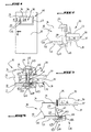
- Figure 1 shows a carpentry, in the occurrence an armored door, comprising a panel 10, an opening 20 cut in the panel 10, a glazing 30 disposed in the opening 20, and fixing means 40 of the glazing 30 on the panel 10, these means being represented in FIGS. 2 to 8.
- the panel 10 defines the general shape of the door and extends in a vertical and horizontal plane. he has a multilayer structure constituted, starting from one side of the door to one side interior, an outer decorative layer 11, a shielding plate 12, with a layer of insulating foam 13, and an interior decorative layer 14.
- the layer of insulating foam 13 is relatively thick to other layers.
- the opening 20 is cut in a part central panel 10 and has a closed contour.
- the opening 20 is rectangular and is delimited by two opposite vertical edges 15 and two horizontal edges opposite 16 of the panel 10.
- the glazing 30 comprises, starting from one side outside the glazing to go to an inner side, an outer pane 31, a vacuum 32, and an anti-burglary pane 33 separated from the outer pane 31 by the vacuum 32.
- the glazing 30 further comprises a seal 34 extending along the entire periphery of the glazing, and disposed in the vacuum 32, between the outer pane 31 and the shielded glass 33. This seal 34 provides the connection between the two panes, and isolates the vacuum 32 from outside.
- the glazing 30 has a rectangular shape, slightly smaller than that of opening 20 and substantially closes this opening 20.
- the glazing 30 has a relatively lower thickness than the panel 10.
- the fastening means 40 include means for mechanically bonding the glazing 30 directly to the armor plate 12.
- the armor plate 12 comprises a part 121 projecting into the opening 20 from the edges of the panel 10, the glazing 30 being mechanically linked to said projecting portion 121.
- the projecting portion 121 of the armor plate 12 extends in the same plane as this armor plate, along at least part of the periphery of the opening 20, and at least along two opposite edges of the panel 10, vertical 15 or horizontal 16.
- this projecting portion 121 extends along the vertical and horizontal edges 16, of continuous way around the entire opening 20.
- the projecting portion 121 extends from the edges vertical 15 and / or horizontal 16 respectively horizontally and vertically, over a width relatively larger than that in gap 37, and extends beyond gap 37, next to the sides glazing 30.
- This protruding part 121 therefore leaves a section free in the opening 20 relatively smaller than the glazing 30. This free section is completely closed by the glazing 30.
- the means to link mechanically the glazing 30 directly to the plate of shielding 12 comprise a metal section 41 adapted to transmit a significant effort of the glazing 30 to the plate shielding 12.
- This metal section 41 extends parallel to the vertical edge 15, practically the entire length of this one.
- this metal profile 41 is a U-shaped profile, comprising a longitudinal core 411 flat, a thin wing 412 standing along a first transverse side of the core 411, and legs of fixing 413 of the profile 41 on the projecting portion 121 of armor plate 12 standing on a second side transverse of the soul 411 opposite the first.
- the projecting portion 121 of the plate 12 comprises fastening holes 122 aligned vertically, in which are engaged the tabs 413 of the profile 41.
- the profile 41 is disposed on a rear side of the protruding part 121, so that the legs, after passing through the orifices 122 come out of a front side of it.
- the legs 413 of the section 41 are shaped such that the profile 41 is movable relative to the projecting portion, by pivoting around the legs 413, between a position tilted relatively closer to the vertical edge 15 of the panel 10 in which the glazing 30 can be set place against the protruding part 121, and a position of keeping the glazing 30 relatively further from the edge vertical 15 of the panel 10.
- the tabs 413 are bent, and comprise each a first rectangular pan 414 integral with the transverse edge of the soul 411 and extending in the same plan as this one, and a second rectangular pan 415 extending the first one from an opposite side to the soul 411 in a direction perpendicular to it.
- the part angle between the two faces is slightly curved.
- the orifices 122 are rectangular, elongated parallel to the vertical edge 15, and arranged at a distance of this edge 15. They have dimensions slightly higher than those in the first panel 414 section, this section being taken in a plane parallel to second pan 415.
- the soul 411 extends substantially perpendicular to the portion protruding 121 of the armor plate 12, the wing 412 and the tabs 413 of the section 41 being turned on one side opposite the vertical edge 15 of the panel 10, towards the glazing 30.
- the second panels 415 of the tabs 413 are plated against an outer side of the projection 121, the wing 412 extending substantially parallel to this protruding part, away from it on the side inside.
- a vertical side 35 of the glazing 30 is engaged in the profile 41, between the wing 412 and the legs 413, and more precisely between the wing 412 and the inner side of the protruding part 121.
- the spacing between the wing 412 and the legs 413 is chosen in such a way that the wing 412 and the side inside the projecting portion 121 are plated respectively on the burglar-proof glass 33 and on the outer pane 31.
- FIG. 4 shows the profile 41 in position tilted.
- the soul 411 extends obliquely to from the inner side of the projection 121, to the vertical edge 15.
- the first sections 414 are engaged each obliquely in the corresponding orifice 122, and the second pan 415 also extend obliquely by relative to the protrusion 121, of an outer side of it.
- the wing 414 then extends in the immediate vicinity of the vertical edge 15, or even against it.
- the glazing 30 in tilted position of the profile 41, can be put in position in the opening 20, against the projecting portion 121, following a movement substantially perpendicular to this projecting part 121.
- the glazing 30 first disposed on an inner side of the panel 10, facing the opening 20, and maintained parallel to this opening.
- orifices 122 then extend along the vertical and / or horizontal sides 16 of the glazed 30, right next to them but very slightly offset to the edge of the panel.
- the inclination of the profiles 41 is such that neither the soul 411 nor the wing 412 interferes with the trajectory glazing 30 when it is put in place.
- the soul 411 comes to press against the edge of the glazing 30, the wing 412 against the burglar-resistant glass 33, and the second sections 415 of the legs 413 against the side outside the projecting portion 121.
- the glazing 30 is perfectly maintained according to a direction perpendicular to the opening 20, since two of its opposite edges at least are imprisoned in profiles 41.
- the fastening means 40 further comprise a clip 42 engaged between the vertical edge 15 of the panel 10 and the profile 41 and blocking it in its position of maintaining, an inner molding 44 secured to the clip 42, and an outer molding 43 integral with the part protruding 121 of the armor plate 12.
- the clip 42 is made of plastic and extends the along the entire vertical edge 15 of the panel 10. It comprises a longitudinal plate 421 bearing on the soul 411 of the profile 41, and longitudinal ribs 422 integral with the plate 421 and resting on the edge vertical 15.
- the plate 421 is substantially rectangular, elongated in the vertical direction, and extends into a plane perpendicular to the protruding part 121. It presents a first large face turned on the side of the glazing 30 and plated on the core 411. The ribs longitudinal projections protrude from a large second face of the plate 421 opposite to the first, and extend mutually parallel to the layer of foam 13.
- the outer and inner moldings 43 and 44 are aluminum profiles extending around the whole glazing 30 to hide the gap 37 between this glazing and the edges of the panel 10.
- the plate 421 of the clip bears on a lateral edge of his first big face opposite the protruding part fastening studs 423 immovably engaged in the inner molding 44.
- the inner molding 44 and clip 42 are mounted together on the door, after installation of glazing 30 and metal profiles 41.
- the inner molding 44 and the clip 42 are arranged facing the opening 20, an inner side of the door, the clip 20 pointing to the glazing 30. Then they are moved to the glazing 30, following a movement perpendicular to this glazing 30, until the part outside of the clip come into the interstice 37, between the side of the glazing and the edge of the panel.
- the ribs 422 are inclined towards inside from plate 421. They allow thus the insertion of clip 42, but oppose the extraction of the clip 42 out of the gap 37.
- the length of the ribs 422 is chosen so that that they rest on the foam layer 13, with enough pressure to create a slight concavity in the foam, taking advantage of the natural elasticity of this foam.
- the outer molding 43 is screwed on the part protruding 121 of the armor plate 12.
- the projecting portion 121 is pierced with conical holes 123 arranged beside the fastening holes 122, screws 124 being engaged in these holes and coming to lodge in threaded holes in the outer molding 43.
- the 124 screw heads are entirely contained in these tapered holes 123.
- the side of the glazing 30 comes to bear on the projection 121 above the conical holes 123, blocking the heads of the screws 124 in these holes.
- the outer molding 43 includes a recess 431 into which the openings of 122. This recess is of sufficient size to allow the movement of the legs 413 of the profile 41 when tilting said profile.
- the outer and inner moldings 43 and 44 are supported on one side on the edge of the panel 10, and the other side on the side of the glazing 30. Seals 46 are interposed between the glazing 30 and the moldings outside and inside.
- the means for fixing the horizontal sides 36 of the glazing 30 on the horizontal edges 16 of the panel 10 are, where appropriate, exactly similar to the means of fixing the vertical sides 35 on the vertical edges 15.
- the glazing 30 can be fixed on two opposite sides only, horizontal or vertical, or three-sided, or four sides. Each side is set to a part corresponding projection 121 of the armor plate 12, using a profile 41.
- the glazing 30 may have any shape, not necessarily rectangular, for example round, oval, triangular, trapezoidal, parallelepipedal, this list is not limiting. He may submit straight sides, or curves. Profiles intended to fix curved sides are also curved.
- the glazing may also not be flat, but present a curvature.
- the profiles will also be curves in this case.
- a force exerted on the glazing 30 is transmitted directly to the armor plate 12. If the effort is exerted from the outside to the inside, it is transmitted through the metal profiles 41, whose material and thickness are chosen so that the profiles can transmit significant efforts without deformation.
- Moldings no longer participate in transmission from the effort to the armor plate.
- the armor plate and the armored glazing forms a continuous surface without solution of continuity between them.
Landscapes
- Engineering & Computer Science (AREA)
- Civil Engineering (AREA)
- Structural Engineering (AREA)
- Securing Of Glass Panes Or The Like (AREA)
- Wing Frames And Configurations (AREA)
- Blinds (AREA)
- Specific Sealing Or Ventilating Devices For Doors And Windows (AREA)
Applications Claiming Priority (2)
| Application Number | Priority Date | Filing Date | Title |
|---|---|---|---|
| FR0400240A FR2864987B1 (fr) | 2004-01-12 | 2004-01-12 | Menuiserie blindee avec vitrage lie directement a la plaque de blindage. |
| FR0400240 | 2004-01-12 |
Publications (3)
| Publication Number | Publication Date |
|---|---|
| EP1553257A2 true EP1553257A2 (de) | 2005-07-13 |
| EP1553257A3 EP1553257A3 (de) | 2006-11-02 |
| EP1553257B1 EP1553257B1 (de) | 2011-11-02 |
Family
ID=34586490
Family Applications (1)
| Application Number | Title | Priority Date | Filing Date |
|---|---|---|---|
| EP05290066A Expired - Lifetime EP1553257B1 (de) | 2004-01-12 | 2005-01-11 | Panzertür oder -fenster mit einer direkt an der Panzerplatte verbundenen Verglasung |
Country Status (5)
| Country | Link |
|---|---|
| EP (1) | EP1553257B1 (de) |
| AT (1) | ATE531889T1 (de) |
| ES (1) | ES2376692T3 (de) |
| FR (1) | FR2864987B1 (de) |
| PT (1) | PT1553257E (de) |
Family Cites Families (4)
| Publication number | Priority date | Publication date | Assignee | Title |
|---|---|---|---|---|
| DE1683343B2 (de) * | 1967-12-11 | 1974-12-05 | Ernst Nipp & Co, 2800 Bremen | Einrichtung zur Befestigung einer Glasscheibe in einem Profilrahmen |
| DE3631566A1 (de) * | 1986-09-17 | 1988-04-14 | Eltreva Ag | Fassadenkonstruktion |
| GB2272244B (en) * | 1992-11-06 | 1996-05-08 | Bowater Windows Ltd | Window frame profile |
| EP1033466A1 (de) * | 1999-02-25 | 2000-09-06 | An der Heiden, Dominik | Vorrichtung zur Sicherung eines Ausfachelementes |
-
2004
- 2004-01-12 FR FR0400240A patent/FR2864987B1/fr not_active Expired - Lifetime
-
2005
- 2005-01-11 ES ES05290066T patent/ES2376692T3/es not_active Expired - Lifetime
- 2005-01-11 PT PT05290066T patent/PT1553257E/pt unknown
- 2005-01-11 AT AT05290066T patent/ATE531889T1/de active
- 2005-01-11 EP EP05290066A patent/EP1553257B1/de not_active Expired - Lifetime
Also Published As
| Publication number | Publication date |
|---|---|
| ES2376692T3 (es) | 2012-03-16 |
| ATE531889T1 (de) | 2011-11-15 |
| PT1553257E (pt) | 2012-02-07 |
| FR2864987B1 (fr) | 2007-07-20 |
| FR2864987A1 (fr) | 2005-07-15 |
| EP1553257B1 (de) | 2011-11-02 |
| EP1553257A3 (de) | 2006-11-02 |
Similar Documents
| Publication | Publication Date | Title |
|---|---|---|
| FR2933438A1 (fr) | Paroi coulissante | |
| FR2912180A1 (fr) | Chassis de porte ou fenetre a ouvrant coulissant comportant un montant vertical d'ouvrant cache. | |
| EP4401996B1 (de) | System zur befestigung einer seitenverglasung eines transportmittels mit einem schloss mit mindestens einer verwechslungssicherungsprojektion | |
| EP4126627B1 (de) | System zum befestigen einer seitenverglasung eines transportmittels mit einem schloss | |
| EP1553257B1 (de) | Panzertür oder -fenster mit einer direkt an der Panzerplatte verbundenen Verglasung | |
| EP4103442B1 (de) | System zum befestigen einer seitenverglasung eines transportmittels mit einem schloss | |
| EP2189599B1 (de) | Stulpschiene für ein Schloss, Schloss mit Stulpschiene und Schiebetür mir einem solchen Schloss | |
| EP0771924B1 (de) | Flügelrahmen für Doppelflügelfenster | |
| FR2839697A1 (fr) | Systeme de montage d'un ouvrant sur une structure de vehicule automobile | |
| EP2189616B1 (de) | Montageverfahren eines Öffnungselements in einer Fassade vom Typ Vorhangfassade | |
| FR2850423A1 (fr) | Dispositif de joint pour systeme de fermeture de baie a au moins un vantail coulissant | |
| FR2770571A3 (fr) | Porte en verre avec bordure speciale | |
| EP2003279B1 (de) | Klappfenster oder Ähnliches mit Rahmen, mit verdecktem Öffnungsflügel | |
| EP1991752B1 (de) | Anordnung aus einer mehrfachverglasungseinheit und einem profil sowie profil für eine verglasungseinheit | |
| EP4185480B1 (de) | Verglasung mit einem fensterhalter in schmaler bauweise und verfahren zur herstellung der verglasung | |
| FR3075245A1 (fr) | Agencement d'une porte a panneau, coupe-feu, avec inserts de fixation et de centrage | |
| FR2883937A1 (fr) | Systeme d'encastrement du bord d'un panneau ou analogue dans un montant | |
| FR2776048A1 (fr) | Profile pour menuiserie du type coulissante | |
| FR2711176A1 (fr) | Procédé pour le montage d'un bloc-porte dans une cloison formée d'une ossature sur laquelle sont rapportées des plaques de plâtre et bloc-porte propre à la mise en oeuvre d'un tel procédé. | |
| FR3150831A1 (fr) | Bloc-porte à blindage anti-effraction | |
| FR2493388A1 (fr) | Survitrage a chassis mobile pour l'isolation thermique des fenetres | |
| FR2769663A1 (fr) | Dispositif de fixation d'une vitre de survitrage | |
| EP1605119A1 (de) | Verriegelungsanordnung für Tür, Fenster oder verschiebbare Fenstertür | |
| FR2913449A1 (fr) | Panneau de separation d'espace a garniture d'absorption des chocs. | |
| FR3017410A1 (fr) | Element d'etancheite pour fenetre ou porte coulissante |
Legal Events
| Date | Code | Title | Description |
|---|---|---|---|
| PUAI | Public reference made under article 153(3) epc to a published international application that has entered the european phase |
Free format text: ORIGINAL CODE: 0009012 |
|
| AK | Designated contracting states |
Kind code of ref document: A2 Designated state(s): AT BE BG CH CY CZ DE DK EE ES FI FR GB GR HU IE IS IT LI LT LU MC NL PL PT RO SE SI SK TR |
|
| AX | Request for extension of the european patent |
Extension state: AL BA HR LV MK YU |
|
| PUAL | Search report despatched |
Free format text: ORIGINAL CODE: 0009013 |
|
| AK | Designated contracting states |
Kind code of ref document: A3 Designated state(s): AT BE BG CH CY CZ DE DK EE ES FI FR GB GR HU IE IS IT LI LT LU MC NL PL PT RO SE SI SK TR |
|
| AX | Request for extension of the european patent |
Extension state: AL BA HR LV MK YU |
|
| 17P | Request for examination filed |
Effective date: 20070426 |
|
| AKX | Designation fees paid |
Designated state(s): AT BE BG CH CY CZ DE DK EE ES FI FR GB GR HU IE IS IT LI LT LU MC NL PL PT RO SE SI SK TR |
|
| RAP1 | Party data changed (applicant data changed or rights of an application transferred) |
Owner name: ASSA ABLOY COTE PICARDE |
|
| GRAP | Despatch of communication of intention to grant a patent |
Free format text: ORIGINAL CODE: EPIDOSNIGR1 |
|
| GRAS | Grant fee paid |
Free format text: ORIGINAL CODE: EPIDOSNIGR3 |
|
| GRAA | (expected) grant |
Free format text: ORIGINAL CODE: 0009210 |
|
| AK | Designated contracting states |
Kind code of ref document: B1 Designated state(s): AT BE BG CH CY CZ DE DK EE ES FI FR GB GR HU IE IS IT LI LT LU MC NL PL PT RO SE SI SK TR |
|
| REG | Reference to a national code |
Ref country code: GB Ref legal event code: FG4D Free format text: NOT ENGLISH |
|
| REG | Reference to a national code |
Ref country code: CH Ref legal event code: EP |
|
| REG | Reference to a national code |
Ref country code: IE Ref legal event code: FG4D |
|
| REG | Reference to a national code |
Ref country code: DE Ref legal event code: R096 Ref document number: 602005030927 Country of ref document: DE Effective date: 20120119 |
|
| REG | Reference to a national code |
Ref country code: PT Ref legal event code: SC4A Free format text: AVAILABILITY OF NATIONAL TRANSLATION Effective date: 20120127 |
|
| REG | Reference to a national code |
Ref country code: NL Ref legal event code: T3 |
|
| REG | Reference to a national code |
Ref country code: CH Ref legal event code: NV Representative=s name: TROESCH SCHEIDEGGER WERNER AG |
|
| REG | Reference to a national code |
Ref country code: ES Ref legal event code: FG2A Ref document number: 2376692 Country of ref document: ES Kind code of ref document: T3 Effective date: 20120316 |
|
| LTIE | Lt: invalidation of european patent or patent extension |
Effective date: 20111102 |
|
| PG25 | Lapsed in a contracting state [announced via postgrant information from national office to epo] |
Ref country code: LT Free format text: LAPSE BECAUSE OF FAILURE TO SUBMIT A TRANSLATION OF THE DESCRIPTION OR TO PAY THE FEE WITHIN THE PRESCRIBED TIME-LIMIT Effective date: 20111102 Ref country code: IS Free format text: LAPSE BECAUSE OF FAILURE TO SUBMIT A TRANSLATION OF THE DESCRIPTION OR TO PAY THE FEE WITHIN THE PRESCRIBED TIME-LIMIT Effective date: 20120302 |
|
| PG25 | Lapsed in a contracting state [announced via postgrant information from national office to epo] |
Ref country code: SI Free format text: LAPSE BECAUSE OF FAILURE TO SUBMIT A TRANSLATION OF THE DESCRIPTION OR TO PAY THE FEE WITHIN THE PRESCRIBED TIME-LIMIT Effective date: 20111102 Ref country code: GR Free format text: LAPSE BECAUSE OF FAILURE TO SUBMIT A TRANSLATION OF THE DESCRIPTION OR TO PAY THE FEE WITHIN THE PRESCRIBED TIME-LIMIT Effective date: 20120203 Ref country code: SE Free format text: LAPSE BECAUSE OF FAILURE TO SUBMIT A TRANSLATION OF THE DESCRIPTION OR TO PAY THE FEE WITHIN THE PRESCRIBED TIME-LIMIT Effective date: 20111102 Ref country code: PL Free format text: LAPSE BECAUSE OF FAILURE TO SUBMIT A TRANSLATION OF THE DESCRIPTION OR TO PAY THE FEE WITHIN THE PRESCRIBED TIME-LIMIT Effective date: 20111102 |
|
| REG | Reference to a national code |
Ref country code: IE Ref legal event code: FD4D |
|
| PG25 | Lapsed in a contracting state [announced via postgrant information from national office to epo] |
Ref country code: CY Free format text: LAPSE BECAUSE OF FAILURE TO SUBMIT A TRANSLATION OF THE DESCRIPTION OR TO PAY THE FEE WITHIN THE PRESCRIBED TIME-LIMIT Effective date: 20111102 |
|
| PG25 | Lapsed in a contracting state [announced via postgrant information from national office to epo] |
Ref country code: IE Free format text: LAPSE BECAUSE OF FAILURE TO SUBMIT A TRANSLATION OF THE DESCRIPTION OR TO PAY THE FEE WITHIN THE PRESCRIBED TIME-LIMIT Effective date: 20111102 Ref country code: EE Free format text: LAPSE BECAUSE OF FAILURE TO SUBMIT A TRANSLATION OF THE DESCRIPTION OR TO PAY THE FEE WITHIN THE PRESCRIBED TIME-LIMIT Effective date: 20111102 Ref country code: DK Free format text: LAPSE BECAUSE OF FAILURE TO SUBMIT A TRANSLATION OF THE DESCRIPTION OR TO PAY THE FEE WITHIN THE PRESCRIBED TIME-LIMIT Effective date: 20111102 Ref country code: SK Free format text: LAPSE BECAUSE OF FAILURE TO SUBMIT A TRANSLATION OF THE DESCRIPTION OR TO PAY THE FEE WITHIN THE PRESCRIBED TIME-LIMIT Effective date: 20111102 Ref country code: CZ Free format text: LAPSE BECAUSE OF FAILURE TO SUBMIT A TRANSLATION OF THE DESCRIPTION OR TO PAY THE FEE WITHIN THE PRESCRIBED TIME-LIMIT Effective date: 20111102 Ref country code: BG Free format text: LAPSE BECAUSE OF FAILURE TO SUBMIT A TRANSLATION OF THE DESCRIPTION OR TO PAY THE FEE WITHIN THE PRESCRIBED TIME-LIMIT Effective date: 20120202 |
|
| PG25 | Lapsed in a contracting state [announced via postgrant information from national office to epo] |
Ref country code: RO Free format text: LAPSE BECAUSE OF FAILURE TO SUBMIT A TRANSLATION OF THE DESCRIPTION OR TO PAY THE FEE WITHIN THE PRESCRIBED TIME-LIMIT Effective date: 20111102 |
|
| PLBE | No opposition filed within time limit |
Free format text: ORIGINAL CODE: 0009261 |
|
| STAA | Information on the status of an ep patent application or granted ep patent |
Free format text: STATUS: NO OPPOSITION FILED WITHIN TIME LIMIT |
|
| REG | Reference to a national code |
Ref country code: AT Ref legal event code: MK05 Ref document number: 531889 Country of ref document: AT Kind code of ref document: T Effective date: 20111102 |
|
| 26N | No opposition filed |
Effective date: 20120803 |
|
| REG | Reference to a national code |
Ref country code: DE Ref legal event code: R097 Ref document number: 602005030927 Country of ref document: DE Effective date: 20120803 |
|
| PG25 | Lapsed in a contracting state [announced via postgrant information from national office to epo] |
Ref country code: AT Free format text: LAPSE BECAUSE OF FAILURE TO SUBMIT A TRANSLATION OF THE DESCRIPTION OR TO PAY THE FEE WITHIN THE PRESCRIBED TIME-LIMIT Effective date: 20111102 |
|
| PG25 | Lapsed in a contracting state [announced via postgrant information from national office to epo] |
Ref country code: FI Free format text: LAPSE BECAUSE OF FAILURE TO SUBMIT A TRANSLATION OF THE DESCRIPTION OR TO PAY THE FEE WITHIN THE PRESCRIBED TIME-LIMIT Effective date: 20111102 |
|
| PG25 | Lapsed in a contracting state [announced via postgrant information from national office to epo] |
Ref country code: TR Free format text: LAPSE BECAUSE OF FAILURE TO SUBMIT A TRANSLATION OF THE DESCRIPTION OR TO PAY THE FEE WITHIN THE PRESCRIBED TIME-LIMIT Effective date: 20111102 |
|
| PG25 | Lapsed in a contracting state [announced via postgrant information from national office to epo] |
Ref country code: HU Free format text: LAPSE BECAUSE OF FAILURE TO SUBMIT A TRANSLATION OF THE DESCRIPTION OR TO PAY THE FEE WITHIN THE PRESCRIBED TIME-LIMIT Effective date: 20050111 |
|
| REG | Reference to a national code |
Ref country code: FR Ref legal event code: PLFP Year of fee payment: 12 |
|
| REG | Reference to a national code |
Ref country code: FR Ref legal event code: PLFP Year of fee payment: 13 |
|
| REG | Reference to a national code |
Ref country code: FR Ref legal event code: PLFP Year of fee payment: 14 |
|
| PGFP | Annual fee paid to national office [announced via postgrant information from national office to epo] |
Ref country code: LU Payment date: 20181224 Year of fee payment: 15 Ref country code: MC Payment date: 20181228 Year of fee payment: 15 |
|
| PGFP | Annual fee paid to national office [announced via postgrant information from national office to epo] |
Ref country code: FR Payment date: 20181227 Year of fee payment: 15 Ref country code: BE Payment date: 20181217 Year of fee payment: 15 |
|
| PGFP | Annual fee paid to national office [announced via postgrant information from national office to epo] |
Ref country code: CH Payment date: 20190115 Year of fee payment: 15 Ref country code: NL Payment date: 20190116 Year of fee payment: 15 Ref country code: ES Payment date: 20190201 Year of fee payment: 15 Ref country code: IT Payment date: 20190121 Year of fee payment: 15 Ref country code: DE Payment date: 20190102 Year of fee payment: 15 Ref country code: GB Payment date: 20190109 Year of fee payment: 15 |
|
| PGFP | Annual fee paid to national office [announced via postgrant information from national office to epo] |
Ref country code: PT Payment date: 20190110 Year of fee payment: 15 |
|
| REG | Reference to a national code |
Ref country code: DE Ref legal event code: R119 Ref document number: 602005030927 Country of ref document: DE |
|
| PG25 | Lapsed in a contracting state [announced via postgrant information from national office to epo] |
Ref country code: MC Free format text: LAPSE BECAUSE OF NON-PAYMENT OF DUE FEES Effective date: 20200131 |
|
| REG | Reference to a national code |
Ref country code: CH Ref legal event code: PL |
|
| REG | Reference to a national code |
Ref country code: NL Ref legal event code: MM Effective date: 20200201 |
|
| GBPC | Gb: european patent ceased through non-payment of renewal fee |
Effective date: 20200111 |
|
| REG | Reference to a national code |
Ref country code: BE Ref legal event code: MM Effective date: 20200131 |
|
| PG25 | Lapsed in a contracting state [announced via postgrant information from national office to epo] |
Ref country code: PT Free format text: LAPSE BECAUSE OF NON-PAYMENT OF DUE FEES Effective date: 20200813 Ref country code: FR Free format text: LAPSE BECAUSE OF NON-PAYMENT OF DUE FEES Effective date: 20200131 Ref country code: LU Free format text: LAPSE BECAUSE OF NON-PAYMENT OF DUE FEES Effective date: 20200111 Ref country code: NL Free format text: LAPSE BECAUSE OF NON-PAYMENT OF DUE FEES Effective date: 20200201 Ref country code: GB Free format text: LAPSE BECAUSE OF NON-PAYMENT OF DUE FEES Effective date: 20200111 Ref country code: DE Free format text: LAPSE BECAUSE OF NON-PAYMENT OF DUE FEES Effective date: 20200801 |
|
| PG25 | Lapsed in a contracting state [announced via postgrant information from national office to epo] |
Ref country code: BE Free format text: LAPSE BECAUSE OF NON-PAYMENT OF DUE FEES Effective date: 20200131 Ref country code: CH Free format text: LAPSE BECAUSE OF NON-PAYMENT OF DUE FEES Effective date: 20200131 Ref country code: LI Free format text: LAPSE BECAUSE OF NON-PAYMENT OF DUE FEES Effective date: 20200131 |
|
| PG25 | Lapsed in a contracting state [announced via postgrant information from national office to epo] |
Ref country code: IT Free format text: LAPSE BECAUSE OF NON-PAYMENT OF DUE FEES Effective date: 20200111 |
|
| REG | Reference to a national code |
Ref country code: ES Ref legal event code: FD2A Effective date: 20210602 |
|
| PG25 | Lapsed in a contracting state [announced via postgrant information from national office to epo] |
Ref country code: ES Free format text: LAPSE BECAUSE OF NON-PAYMENT OF DUE FEES Effective date: 20200112 |