EP1553237A1 - Decke und Wand und Trogelement dafür - Google Patents
Decke und Wand und Trogelement dafür Download PDFInfo
- Publication number
- EP1553237A1 EP1553237A1 EP04293156A EP04293156A EP1553237A1 EP 1553237 A1 EP1553237 A1 EP 1553237A1 EP 04293156 A EP04293156 A EP 04293156A EP 04293156 A EP04293156 A EP 04293156A EP 1553237 A1 EP1553237 A1 EP 1553237A1
- Authority
- EP
- European Patent Office
- Prior art keywords
- chute
- channel
- elements
- ducts
- section
- Prior art date
- Legal status (The legal status is an assumption and is not a legal conclusion. Google has not performed a legal analysis and makes no representation as to the accuracy of the status listed.)
- Granted
Links
Images

Classifications
-
- F—MECHANICAL ENGINEERING; LIGHTING; HEATING; WEAPONS; BLASTING
- F24—HEATING; RANGES; VENTILATING
- F24D—DOMESTIC- OR SPACE-HEATING SYSTEMS, e.g. CENTRAL HEATING SYSTEMS; DOMESTIC HOT-WATER SUPPLY SYSTEMS; ELEMENTS OR COMPONENTS THEREFOR
- F24D3/00—Hot-water central heating systems
- F24D3/12—Tube and panel arrangements for ceiling, wall, or underfloor heating
- F24D3/14—Tube and panel arrangements for ceiling, wall, or underfloor heating incorporated in a ceiling, wall or floor
- F24D3/141—Tube mountings specially adapted therefor
- F24D3/142—Tube mountings specially adapted therefor integrated in prefab construction elements
-
- E—FIXED CONSTRUCTIONS
- E04—BUILDING
- E04B—GENERAL BUILDING CONSTRUCTIONS; WALLS, e.g. PARTITIONS; ROOFS; FLOORS; CEILINGS; INSULATION OR OTHER PROTECTION OF BUILDINGS
- E04B5/00—Floors; Floor construction with regard to insulation; Connections specially adapted therefor
- E04B5/48—Special adaptations of floors for incorporating ducts, e.g. for heating or ventilating
-
- F—MECHANICAL ENGINEERING; LIGHTING; HEATING; WEAPONS; BLASTING
- F16—ENGINEERING ELEMENTS AND UNITS; GENERAL MEASURES FOR PRODUCING AND MAINTAINING EFFECTIVE FUNCTIONING OF MACHINES OR INSTALLATIONS; THERMAL INSULATION IN GENERAL
- F16L—PIPES; JOINTS OR FITTINGS FOR PIPES; SUPPORTS FOR PIPES, CABLES OR PROTECTIVE TUBING; MEANS FOR THERMAL INSULATION IN GENERAL
- F16L3/00—Supports for pipes, cables or protective tubing, e.g. hangers, holders, clamps, cleats, clips, brackets
- F16L3/08—Supports for pipes, cables or protective tubing, e.g. hangers, holders, clamps, cleats, clips, brackets substantially surrounding the pipe, cable or protective tubing
- F16L3/12—Supports for pipes, cables or protective tubing, e.g. hangers, holders, clamps, cleats, clips, brackets substantially surrounding the pipe, cable or protective tubing comprising a member substantially surrounding the pipe, cable or protective tubing
- F16L3/1226—Supports for pipes, cables or protective tubing, e.g. hangers, holders, clamps, cleats, clips, brackets substantially surrounding the pipe, cable or protective tubing comprising a member substantially surrounding the pipe, cable or protective tubing elongated supports, e.g. to support a curved pipe
-
- F—MECHANICAL ENGINEERING; LIGHTING; HEATING; WEAPONS; BLASTING
- F16—ENGINEERING ELEMENTS AND UNITS; GENERAL MEASURES FOR PRODUCING AND MAINTAINING EFFECTIVE FUNCTIONING OF MACHINES OR INSTALLATIONS; THERMAL INSULATION IN GENERAL
- F16L—PIPES; JOINTS OR FITTINGS FOR PIPES; SUPPORTS FOR PIPES, CABLES OR PROTECTIVE TUBING; MEANS FOR THERMAL INSULATION IN GENERAL
- F16L3/00—Supports for pipes, cables or protective tubing, e.g. hangers, holders, clamps, cleats, clips, brackets
- F16L3/22—Supports for pipes, cables or protective tubing, e.g. hangers, holders, clamps, cleats, clips, brackets specially adapted for supporting a number of parallel pipes at intervals
- F16L3/223—Supports for pipes, cables or protective tubing, e.g. hangers, holders, clamps, cleats, clips, brackets specially adapted for supporting a number of parallel pipes at intervals each support having one transverse base for supporting the pipes
-
- F—MECHANICAL ENGINEERING; LIGHTING; HEATING; WEAPONS; BLASTING
- F16—ENGINEERING ELEMENTS AND UNITS; GENERAL MEASURES FOR PRODUCING AND MAINTAINING EFFECTIVE FUNCTIONING OF MACHINES OR INSTALLATIONS; THERMAL INSULATION IN GENERAL
- F16L—PIPES; JOINTS OR FITTINGS FOR PIPES; SUPPORTS FOR PIPES, CABLES OR PROTECTIVE TUBING; MEANS FOR THERMAL INSULATION IN GENERAL
- F16L3/00—Supports for pipes, cables or protective tubing, e.g. hangers, holders, clamps, cleats, clips, brackets
- F16L3/26—Supports for pipes, cables or protective tubing, e.g. hangers, holders, clamps, cleats, clips, brackets specially adapted for supporting the pipes all along their length, e.g. pipe channels or ducts
-
- H—ELECTRICITY
- H02—GENERATION; CONVERSION OR DISTRIBUTION OF ELECTRIC POWER
- H02G—INSTALLATION OF ELECTRIC CABLES OR LINES, OR OF COMBINED OPTICAL AND ELECTRIC CABLES OR LINES
- H02G3/00—Installations of electric cables or lines or protective tubing therefor in or on buildings, equivalent structures or vehicles
- H02G3/36—Installations of cables or lines in walls, floors or ceilings
- H02G3/38—Installations of cables or lines in walls, floors or ceilings the cables or lines being installed in preestablished conduits or ducts
-
- Y—GENERAL TAGGING OF NEW TECHNOLOGICAL DEVELOPMENTS; GENERAL TAGGING OF CROSS-SECTIONAL TECHNOLOGIES SPANNING OVER SEVERAL SECTIONS OF THE IPC; TECHNICAL SUBJECTS COVERED BY FORMER USPC CROSS-REFERENCE ART COLLECTIONS [XRACs] AND DIGESTS
- Y02—TECHNOLOGIES OR APPLICATIONS FOR MITIGATION OR ADAPTATION AGAINST CLIMATE CHANGE
- Y02B—CLIMATE CHANGE MITIGATION TECHNOLOGIES RELATED TO BUILDINGS, e.g. HOUSING, HOUSE APPLIANCES OR RELATED END-USER APPLICATIONS
- Y02B30/00—Energy efficient heating, ventilation or air conditioning [HVAC]
Definitions
- a vertical or horizontal wall of a real estate construction includes a support structure on which, on the inside of the wall, there is a insulation formed most often of plates.
- the structure is more complex and includes, above a support (floor, slab of compression ...), a material of reinforcement forming a layer 4 to 5 centimeters thick allowing a catching up inequalities of the slab and, above all, offering the pipelines for sanitary fluids or electrical conduits an installation space in which they are embedded. Incorporated in this layer of restoration, these pipelines are no longer an obstacle to setting up of insulating material on which will be arranged the heating heat pipes.
- These pipes are usually embedded in a coating layer.
- the thermal insulation and / or sound insulation is the most often cut to clear a passage along the walls for a duct or bundle of ducts, which creates a solution in the continuity of insulation and the formation of a thermal bridge if we do not take the precaution to restore the insulation in the neighborhood of these pipes.
- the invention is primarily concerned with chute for horizontal or vertical walls covered with an insulation layer, made of thermal insulating material and / or phonic composed of a lower base defining a channel to accommodate ducts or ducts and hood to cover the channel.
- the chute according to the invention constitutes a guide for placement and maintenance of sanitary water pipes or electrical conduits and this, in an insulating material and in a space defined by the thickness of the coating insulating.
- the chute has a dual function that of guide and maintain the pipes and ducts and to complete at the place of their passage the layer insulation while ensuring the continuity of the surface top of this layer and ensuring homogeneity compressive strength over the entire layer insulating.
- this chute is made of prefabricated way in sections, each section having a hood element and a base element and having at the end alignment means to ensure the continuity of the geometry of the chute of a section to the other.
- These alignment means make it possible to arrange an upper surface of the hood without a solution continuity or shift between two consecutive sections.
- each basic element has in the channel in one piece with him means for clipping the pipes or ducts it receives.
- the ducts and pipes are thus immobilized at inside the chute formed by the sections successive stages and also serve as reinforcement, rigidification of these sections.
- the chute is of section rectangular whose thickness is adjustable by the use of hoods of different thicknesses. Indeed we know he There are several types of insulating cladding boards that differ essentially in thicknesses from 47 to 70 mm. With a single chute base and hoods different thicknesses, for example three kinds of covers, we cover most of the needs of the market.
- the chute has rectilinear elements and corner elements, the channel corner elements being curved.
- the hood elements and the basic elements of a chunk section include means for their mutual snapping after the laying of the pipes.
- the subject of the invention is a floor or a vertical wall comprising a support structure and a insulating coating on this structure formed of plates juxtaposed of determined thickness, in which the insulating coating includes the aforesaid chute.
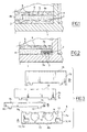
- Figure 1 is represented by a section partial and schematic the classical realization of a heated floor on a support structure formed here by a slab 1 of compression. On this slab so, we realizes a so-called layer of rubbedage 2 which makes it possible to drown piping hot and cold sanitary water or electrical conductor sleeves 3. Above this layer of waste 2 the floor has a coating thermal insulation formed by the juxtaposition of several plates of insulating material 4a, 4b. Above this insulating material, the floor has pipes heat carriers 5 formed either by resistors electric or by hot water pipes, forming heat exchanger and embedded in a screed 6 which will form the support of a non-slip flooring represent. Clevis 6 is in some embodiments has been replaced by a thick layer that ensures same time as the coating, the bonding of the flooring which is a tile.
- the function of the covering 2 is essential to constitute a thickness in which can be housed ducts and pipes 3.
- a secondary role of this coating is to make up for unevenness of the upper surface of the slab compression 1 but these are becoming more and more weak with the modern methods of achieving these slabs.
- the operation of renovation requires a manpower important on the site.
- FIG 2 there is shown a floor consistent to the invention in which above the slab 1 there There is no longer any need for a blanket 2.
- slab 1 directly supports panels or plates 4 insulation and, for example at the corner of a wall, a chute 7 whose thickness is equal to the thickness of the plates 4 and which constitutes a channel for the passage of ducts and ducts 3.
- a chute 7 Above the formed set by the insulation plates 4 and the chute 7 which is itself into an insulation material, we proceed to the in place of the exchangers 5 and the production of the screed 6.
- Another advantage of this chute is that the 3 pipes are thermally insulated by the same material of the chute and this, much more effectively than when embedded in a coating of screed.
- a chute 7 is made in two parts namely a base element 7a and a cover 7b which covers the basic element 7a.
- the basic element 7a is made under shape of sections such as that shown in FIG. 4, made of an insulating material (expanded polystyrene by example). It comprises a channel formed here by two cylindrical housings 9 which open on the face 8a of each section 8 by an opening 10. width of this opening 10 is smaller than the diameter of these cylindrical housings or more exactly to the diameter ducts or ducts that these dwellings must accommodate.
- the pipes 3 are therefore introduced by force in the housings 9 whose walls and opening 10 reduced form means of clipping these pipes 3 in the base element 7a.
- each end element section 8 seen at the end has one end of the lugs 13 while its other end is provided with housing 14 capable of accommodating 13.
- Each end may also be alternative equipped with a lug and a housing.
- These lugs and housing are means for aligning end to ends of the basic building blocks in order to preserve the continuity of the profile of a chute including ensuring their relative maintenance during their implementation.
- the lower face 8b of each section 8 and the upper side of each lid have grooves 15, 16 which for the basic element 7a are visible in FIG. 4. These grooves constitute sawing guides or cutting sections 8 for get correct cuts or skews so, by example, to make the arrangement illustrated by the figure 5.
- Figure 5 illustrates a way of achieving a chute in a floor angle from sections cut of basic elements and of course lids. It is understood that because of the nature of the material constituting its basic elements (expanded polystyrene), can quite easily accommodate a pipe or sheath bent at 90 ° in a chute that offers instead of a bend a three-sided polygon representing approximately the quarter circle borrowed by the ducting or sheath.
- the deformability of the material and the length of the base element section 17 forming the connection between the two perpendicular sections 18 and 19 allow to take into account practically all radii of curvature.
- the advantage of this realization lies in the fact that it is not necessary to provide particular corner pieces.
- the disadvantage lies in the makes it necessary to provide a filling of the angle of the floor beyond section 17.
- a corner element 20 as shown in FIG. 6 whose channel 21 is curve and which is covered by a lid 22 of form corresponding to the shape of the corner element.
- a lug of clipping 23 is planned in the center of channel 21 while ribs and grooves 24, 25 are provided in correspondence between the base member 20 and the lid 22.
- lids or hoods 22 of several thicknesses to accommodate varieties likely to be met with regard to the thickness of the plates of insulating material.
- the chute is flush with the free surface of the insulation 4 and the wall can receive any finishing siding without that a thermal bridge or a break has been created sound insulation between the outside and the inside of habitat.
- the provisions illustrated by Figures 5 and 6 apply for example between the lower (or upper) edge of a wall and an edge side of it to guide bent pipes between a vertical section and a horizontal section.
Landscapes
- Engineering & Computer Science (AREA)
- General Engineering & Computer Science (AREA)
- Mechanical Engineering (AREA)
- Architecture (AREA)
- Civil Engineering (AREA)
- Physics & Mathematics (AREA)
- Structural Engineering (AREA)
- Electromagnetism (AREA)
- Thermal Sciences (AREA)
- Chemical & Material Sciences (AREA)
- Combustion & Propulsion (AREA)
- Building Environments (AREA)
- Floor Finish (AREA)
Priority Applications (1)
| Application Number | Priority Date | Filing Date | Title |
|---|---|---|---|
| PL04293156T PL1553237T3 (pl) | 2004-01-09 | 2004-12-29 | Korytko dla podłóg i ścian konstrukcyjnych |
Applications Claiming Priority (4)
| Application Number | Priority Date | Filing Date | Title |
|---|---|---|---|
| FR0400167A FR2864976A1 (fr) | 2004-01-09 | 2004-01-09 | Plancher chauffant et goulotte pour sa realisation |
| FR0400167 | 2004-01-09 | ||
| FR0405567 | 2004-05-24 | ||
| FR0405567A FR2864977B1 (fr) | 2004-01-09 | 2004-05-24 | Plancher et paroi de construction et goulotte pour leur realisation |
Publications (2)
| Publication Number | Publication Date |
|---|---|
| EP1553237A1 true EP1553237A1 (de) | 2005-07-13 |
| EP1553237B1 EP1553237B1 (de) | 2017-02-08 |
Family
ID=34593704
Family Applications (1)
| Application Number | Title | Priority Date | Filing Date |
|---|---|---|---|
| EP04293156.8A Expired - Lifetime EP1553237B1 (de) | 2004-01-09 | 2004-12-29 | Trogelement für Decke und Wand |
Country Status (4)
| Country | Link |
|---|---|
| EP (1) | EP1553237B1 (de) |
| ES (1) | ES2622449T3 (de) |
| FR (1) | FR2864977B1 (de) |
| PL (1) | PL1553237T3 (de) |
Cited By (1)
| Publication number | Priority date | Publication date | Assignee | Title |
|---|---|---|---|---|
| EP2189695A1 (de) | 2008-11-25 | 2010-05-26 | Geberit International AG | Rohrbogenstütze |
Citations (6)
| Publication number | Priority date | Publication date | Assignee | Title |
|---|---|---|---|---|
| GB1432566A (en) * | 1972-04-15 | 1976-04-22 | Oxford Double Glazing Ltd | Ducting assemblies |
| FR2581435A1 (fr) * | 1985-05-02 | 1986-11-07 | Ega Ltd | Pince pour la fixation de tuyauteries |
| DE3720554A1 (de) * | 1987-06-22 | 1989-01-05 | Gerhard Herzog | Plattenfoermiges bauelement |
| GB2233731A (en) * | 1989-07-15 | 1991-01-16 | Peter Charles Bilyard | Carpetting on ducted conduit |
| US5042569A (en) * | 1988-11-04 | 1991-08-27 | Siegmund Gmbh | Surface element for a heatable floor with hollow spaces |
| DE29807539U1 (de) * | 1998-04-29 | 1998-09-03 | Schiermayer, Horst, 09235 Burkhardtsdorf | Gebäudedecke und darin integrierbare Kabelführung |
-
2004
- 2004-05-24 FR FR0405567A patent/FR2864977B1/fr not_active Expired - Lifetime
- 2004-12-29 EP EP04293156.8A patent/EP1553237B1/de not_active Expired - Lifetime
- 2004-12-29 PL PL04293156T patent/PL1553237T3/pl unknown
- 2004-12-29 ES ES04293156.8T patent/ES2622449T3/es not_active Expired - Lifetime
Patent Citations (6)
| Publication number | Priority date | Publication date | Assignee | Title |
|---|---|---|---|---|
| GB1432566A (en) * | 1972-04-15 | 1976-04-22 | Oxford Double Glazing Ltd | Ducting assemblies |
| FR2581435A1 (fr) * | 1985-05-02 | 1986-11-07 | Ega Ltd | Pince pour la fixation de tuyauteries |
| DE3720554A1 (de) * | 1987-06-22 | 1989-01-05 | Gerhard Herzog | Plattenfoermiges bauelement |
| US5042569A (en) * | 1988-11-04 | 1991-08-27 | Siegmund Gmbh | Surface element for a heatable floor with hollow spaces |
| GB2233731A (en) * | 1989-07-15 | 1991-01-16 | Peter Charles Bilyard | Carpetting on ducted conduit |
| DE29807539U1 (de) * | 1998-04-29 | 1998-09-03 | Schiermayer, Horst, 09235 Burkhardtsdorf | Gebäudedecke und darin integrierbare Kabelführung |
Cited By (1)
| Publication number | Priority date | Publication date | Assignee | Title |
|---|---|---|---|---|
| EP2189695A1 (de) | 2008-11-25 | 2010-05-26 | Geberit International AG | Rohrbogenstütze |
Also Published As
| Publication number | Publication date |
|---|---|
| EP1553237B1 (de) | 2017-02-08 |
| FR2864977B1 (fr) | 2007-10-26 |
| FR2864977A1 (fr) | 2005-07-15 |
| PL1553237T3 (pl) | 2017-07-31 |
| ES2622449T3 (es) | 2017-07-06 |
Similar Documents
| Publication | Publication Date | Title |
|---|---|---|
| EP1196665B1 (de) | Grundelement für die einrichtung eines thermischen unterbrechers zwischen einer wand und einer betonplatte und gebäudestruktur mit entsprechender anwendung | |
| FR2698432A1 (fr) | Dalle chauffante d'un plancher modulaire à système de chauffage électrique par le sol, plancher modulaire et montage d'un tel plancher. | |
| EP1553237B1 (de) | Trogelement für Decke und Wand | |
| FR2765906A1 (fr) | Element modulaire leger pour plancher, notamment de batiment | |
| FR2864976A1 (fr) | Plancher chauffant et goulotte pour sa realisation | |
| FR2963372A1 (fr) | Element prefabrique pour le passage de gaines techniques. | |
| EP0070770A1 (de) | Vorrichtung zur Auflage eines Fussbodens auf einer Mauer und Konstruktionsverfahren hierfür | |
| FR2827620A1 (fr) | Dispositif de liaison realisant,de maniere isolee thermiquement,la liaison entre au moins deux parois d'une construction,et procede de realisation d'un tel dispositif | |
| FR2755713A1 (fr) | Element de construction en terre cuite | |
| EP2481863A2 (de) | Dämmverkleidungsplatte für die Bauindustrie | |
| FR2859744A1 (fr) | Panneau prefabrique pour la realisation de parois porteuses chauffantes et/ou rafraichissantes de batiments, et les parois porteuses obtenues au moyen de tels panneaux | |
| FR2458643A1 (fr) | Element de construction | |
| FR2948706A1 (fr) | Entrevous modulable | |
| FR2538511A1 (fr) | Module chauffant et isolant | |
| EP3184711A1 (de) | Dämmplatten aus steinwolle, dämmsystem und verfahren zum verlegen | |
| FR2912437A1 (fr) | Planelle isolante pour batiment. | |
| EP0767281B1 (de) | Verfahren zur Errichtung von Wänden aus modularen Bauelementen mit integrierten Leitungen und Verkleidung | |
| EP2543786A1 (de) | Halterung zur Positionsbeibehaltung einer Leitung bei der Herstellung einer Mörtelschicht | |
| FR2569746A1 (fr) | Perfectionnement aux hourdis comportant l'isolant integre, et son mode de fabrication | |
| EP1553238B1 (de) | Bauteil für geheizten Fussboden | |
| FR3072400A1 (fr) | Element de construction avec repere de reservation et procede de fabrication associe | |
| CA2018135C (fr) | Systeme de drainage a double niveau pour toiture plate | |
| FR2483577A1 (fr) | Installation de chauffage par rayonnement des conduites a circulation d'air | |
| FR2823778A1 (fr) | Plaque d'isolation thermique pour passage de porte interieure | |
| BE1018646A3 (fr) | Brique en beton et systeme de mur en briques. |
Legal Events
| Date | Code | Title | Description |
|---|---|---|---|
| PUAI | Public reference made under article 153(3) epc to a published international application that has entered the european phase |
Free format text: ORIGINAL CODE: 0009012 |
|
| AK | Designated contracting states |
Kind code of ref document: A1 Designated state(s): AT BE BG CH CY CZ DE DK EE ES FI FR GB GR HU IE IS IT LI LT LU MC NL PL PT RO SE SI SK TR |
|
| AX | Request for extension of the european patent |
Extension state: AL BA HR LV MK YU |
|
| 17P | Request for examination filed |
Effective date: 20051206 |
|
| AKX | Designation fees paid |
Designated state(s): AT BE BG CH CY CZ DE DK EE ES FI FR GB GR HU IE IS IT LI LT LU MC NL PL PT RO SE SI SK TR |
|
| 17Q | First examination report despatched |
Effective date: 20160209 |
|
| GRAP | Despatch of communication of intention to grant a patent |
Free format text: ORIGINAL CODE: EPIDOSNIGR1 |
|
| INTG | Intention to grant announced |
Effective date: 20160718 |
|
| GRAJ | Information related to disapproval of communication of intention to grant by the applicant or resumption of examination proceedings by the epo deleted |
Free format text: ORIGINAL CODE: EPIDOSDIGR1 |
|
| STAA | Information on the status of an ep patent application or granted ep patent |
Free format text: STATUS: EXAMINATION IS IN PROGRESS |
|
| GRAR | Information related to intention to grant a patent recorded |
Free format text: ORIGINAL CODE: EPIDOSNIGR71 |
|
| GRAS | Grant fee paid |
Free format text: ORIGINAL CODE: EPIDOSNIGR3 |
|
| STAA | Information on the status of an ep patent application or granted ep patent |
Free format text: STATUS: GRANT OF PATENT IS INTENDED |
|
| INTC | Intention to grant announced (deleted) | ||
| INTG | Intention to grant announced |
Effective date: 20161124 |
|
| GRAA | (expected) grant |
Free format text: ORIGINAL CODE: 0009210 |
|
| STAA | Information on the status of an ep patent application or granted ep patent |
Free format text: STATUS: THE PATENT HAS BEEN GRANTED |
|
| AK | Designated contracting states |
Kind code of ref document: B1 Designated state(s): AT BE BG CH CY CZ DE DK EE ES FI FR GB GR HU IE IS IT LI LT LU MC NL PL PT RO SE SI SK TR |
|
| REG | Reference to a national code |
Ref country code: GB Ref legal event code: FG4D Free format text: NOT ENGLISH |
|
| REG | Reference to a national code |
Ref country code: AT Ref legal event code: REF Ref document number: 866953 Country of ref document: AT Kind code of ref document: T Effective date: 20170215 Ref country code: CH Ref legal event code: EP |
|
| REG | Reference to a national code |
Ref country code: IE Ref legal event code: FG4D Free format text: LANGUAGE OF EP DOCUMENT: FRENCH |
|
| REG | Reference to a national code |
Ref country code: DE Ref legal event code: R096 Ref document number: 602004050757 Country of ref document: DE |
|
| REG | Reference to a national code |
Ref country code: NL Ref legal event code: FP |
|
| REG | Reference to a national code |
Ref country code: LT Ref legal event code: MG4D |
|
| REG | Reference to a national code |
Ref country code: ES Ref legal event code: FG2A Ref document number: 2622449 Country of ref document: ES Kind code of ref document: T3 Effective date: 20170706 |
|
| REG | Reference to a national code |
Ref country code: AT Ref legal event code: MK05 Ref document number: 866953 Country of ref document: AT Kind code of ref document: T Effective date: 20170208 |
|
| PG25 | Lapsed in a contracting state [announced via postgrant information from national office to epo] |
Ref country code: FI Free format text: LAPSE BECAUSE OF FAILURE TO SUBMIT A TRANSLATION OF THE DESCRIPTION OR TO PAY THE FEE WITHIN THE PRESCRIBED TIME-LIMIT Effective date: 20170208 Ref country code: GR Free format text: LAPSE BECAUSE OF FAILURE TO SUBMIT A TRANSLATION OF THE DESCRIPTION OR TO PAY THE FEE WITHIN THE PRESCRIBED TIME-LIMIT Effective date: 20170509 Ref country code: LT Free format text: LAPSE BECAUSE OF FAILURE TO SUBMIT A TRANSLATION OF THE DESCRIPTION OR TO PAY THE FEE WITHIN THE PRESCRIBED TIME-LIMIT Effective date: 20170208 |
|
| PG25 | Lapsed in a contracting state [announced via postgrant information from national office to epo] |
Ref country code: AT Free format text: LAPSE BECAUSE OF FAILURE TO SUBMIT A TRANSLATION OF THE DESCRIPTION OR TO PAY THE FEE WITHIN THE PRESCRIBED TIME-LIMIT Effective date: 20170208 Ref country code: PT Free format text: LAPSE BECAUSE OF FAILURE TO SUBMIT A TRANSLATION OF THE DESCRIPTION OR TO PAY THE FEE WITHIN THE PRESCRIBED TIME-LIMIT Effective date: 20170608 Ref country code: BG Free format text: LAPSE BECAUSE OF FAILURE TO SUBMIT A TRANSLATION OF THE DESCRIPTION OR TO PAY THE FEE WITHIN THE PRESCRIBED TIME-LIMIT Effective date: 20170508 Ref country code: SE Free format text: LAPSE BECAUSE OF FAILURE TO SUBMIT A TRANSLATION OF THE DESCRIPTION OR TO PAY THE FEE WITHIN THE PRESCRIBED TIME-LIMIT Effective date: 20170208 |
|
| PG25 | Lapsed in a contracting state [announced via postgrant information from national office to epo] |
Ref country code: CZ Free format text: LAPSE BECAUSE OF FAILURE TO SUBMIT A TRANSLATION OF THE DESCRIPTION OR TO PAY THE FEE WITHIN THE PRESCRIBED TIME-LIMIT Effective date: 20170208 Ref country code: EE Free format text: LAPSE BECAUSE OF FAILURE TO SUBMIT A TRANSLATION OF THE DESCRIPTION OR TO PAY THE FEE WITHIN THE PRESCRIBED TIME-LIMIT Effective date: 20170208 Ref country code: IT Free format text: LAPSE BECAUSE OF FAILURE TO SUBMIT A TRANSLATION OF THE DESCRIPTION OR TO PAY THE FEE WITHIN THE PRESCRIBED TIME-LIMIT Effective date: 20170208 Ref country code: SK Free format text: LAPSE BECAUSE OF FAILURE TO SUBMIT A TRANSLATION OF THE DESCRIPTION OR TO PAY THE FEE WITHIN THE PRESCRIBED TIME-LIMIT Effective date: 20170208 Ref country code: RO Free format text: LAPSE BECAUSE OF FAILURE TO SUBMIT A TRANSLATION OF THE DESCRIPTION OR TO PAY THE FEE WITHIN THE PRESCRIBED TIME-LIMIT Effective date: 20170208 |
|
| REG | Reference to a national code |
Ref country code: DE Ref legal event code: R097 Ref document number: 602004050757 Country of ref document: DE |
|
| PG25 | Lapsed in a contracting state [announced via postgrant information from national office to epo] |
Ref country code: DK Free format text: LAPSE BECAUSE OF FAILURE TO SUBMIT A TRANSLATION OF THE DESCRIPTION OR TO PAY THE FEE WITHIN THE PRESCRIBED TIME-LIMIT Effective date: 20170208 |
|
| PLBE | No opposition filed within time limit |
Free format text: ORIGINAL CODE: 0009261 |
|
| STAA | Information on the status of an ep patent application or granted ep patent |
Free format text: STATUS: NO OPPOSITION FILED WITHIN TIME LIMIT |
|
| REG | Reference to a national code |
Ref country code: FR Ref legal event code: PLFP Year of fee payment: 14 |
|
| 26N | No opposition filed |
Effective date: 20171109 |
|
| PG25 | Lapsed in a contracting state [announced via postgrant information from national office to epo] |
Ref country code: SI Free format text: LAPSE BECAUSE OF FAILURE TO SUBMIT A TRANSLATION OF THE DESCRIPTION OR TO PAY THE FEE WITHIN THE PRESCRIBED TIME-LIMIT Effective date: 20170208 |
|
| REG | Reference to a national code |
Ref country code: DE Ref legal event code: R119 Ref document number: 602004050757 Country of ref document: DE |
|
| REG | Reference to a national code |
Ref country code: CH Ref legal event code: PL |
|
| REG | Reference to a national code |
Ref country code: IE Ref legal event code: MM4A |
|
| PG25 | Lapsed in a contracting state [announced via postgrant information from national office to epo] |
Ref country code: DE Free format text: LAPSE BECAUSE OF NON-PAYMENT OF DUE FEES Effective date: 20180703 Ref country code: IE Free format text: LAPSE BECAUSE OF NON-PAYMENT OF DUE FEES Effective date: 20171229 |
|
| PG25 | Lapsed in a contracting state [announced via postgrant information from national office to epo] |
Ref country code: CH Free format text: LAPSE BECAUSE OF NON-PAYMENT OF DUE FEES Effective date: 20171231 Ref country code: LI Free format text: LAPSE BECAUSE OF NON-PAYMENT OF DUE FEES Effective date: 20171231 |
|
| PG25 | Lapsed in a contracting state [announced via postgrant information from national office to epo] |
Ref country code: HU Free format text: LAPSE BECAUSE OF FAILURE TO SUBMIT A TRANSLATION OF THE DESCRIPTION OR TO PAY THE FEE WITHIN THE PRESCRIBED TIME-LIMIT; INVALID AB INITIO Effective date: 20041229 Ref country code: MC Free format text: LAPSE BECAUSE OF FAILURE TO SUBMIT A TRANSLATION OF THE DESCRIPTION OR TO PAY THE FEE WITHIN THE PRESCRIBED TIME-LIMIT Effective date: 20170208 |
|
| PG25 | Lapsed in a contracting state [announced via postgrant information from national office to epo] |
Ref country code: CY Free format text: LAPSE BECAUSE OF NON-PAYMENT OF DUE FEES Effective date: 20170208 |
|
| PGFP | Annual fee paid to national office [announced via postgrant information from national office to epo] |
Ref country code: NL Payment date: 20191219 Year of fee payment: 16 |
|
| PGFP | Annual fee paid to national office [announced via postgrant information from national office to epo] |
Ref country code: BE Payment date: 20191219 Year of fee payment: 16 Ref country code: PL Payment date: 20191122 Year of fee payment: 16 Ref country code: LU Payment date: 20191219 Year of fee payment: 16 |
|
| PG25 | Lapsed in a contracting state [announced via postgrant information from national office to epo] |
Ref country code: TR Free format text: LAPSE BECAUSE OF FAILURE TO SUBMIT A TRANSLATION OF THE DESCRIPTION OR TO PAY THE FEE WITHIN THE PRESCRIBED TIME-LIMIT Effective date: 20170208 |
|
| PGFP | Annual fee paid to national office [announced via postgrant information from national office to epo] |
Ref country code: ES Payment date: 20200121 Year of fee payment: 16 Ref country code: GB Payment date: 20191220 Year of fee payment: 16 |
|
| PG25 | Lapsed in a contracting state [announced via postgrant information from national office to epo] |
Ref country code: IS Free format text: LAPSE BECAUSE OF FAILURE TO SUBMIT A TRANSLATION OF THE DESCRIPTION OR TO PAY THE FEE WITHIN THE PRESCRIBED TIME-LIMIT Effective date: 20170608 |
|
| REG | Reference to a national code |
Ref country code: NL Ref legal event code: MM Effective date: 20210101 |
|
| GBPC | Gb: european patent ceased through non-payment of renewal fee |
Effective date: 20201229 |
|
| REG | Reference to a national code |
Ref country code: BE Ref legal event code: MM Effective date: 20201231 |
|
| PG25 | Lapsed in a contracting state [announced via postgrant information from national office to epo] |
Ref country code: NL Free format text: LAPSE BECAUSE OF NON-PAYMENT OF DUE FEES Effective date: 20210101 |
|
| PG25 | Lapsed in a contracting state [announced via postgrant information from national office to epo] |
Ref country code: LU Free format text: LAPSE BECAUSE OF NON-PAYMENT OF DUE FEES Effective date: 20201229 |
|
| PG25 | Lapsed in a contracting state [announced via postgrant information from national office to epo] |
Ref country code: GB Free format text: LAPSE BECAUSE OF NON-PAYMENT OF DUE FEES Effective date: 20201229 |
|
| REG | Reference to a national code |
Ref country code: ES Ref legal event code: FD2A Effective date: 20220412 |
|
| PG25 | Lapsed in a contracting state [announced via postgrant information from national office to epo] |
Ref country code: ES Free format text: LAPSE BECAUSE OF NON-PAYMENT OF DUE FEES Effective date: 20201230 Ref country code: BE Free format text: LAPSE BECAUSE OF NON-PAYMENT OF DUE FEES Effective date: 20201231 |
|
| PG25 | Lapsed in a contracting state [announced via postgrant information from national office to epo] |
Ref country code: PL Free format text: LAPSE BECAUSE OF NON-PAYMENT OF DUE FEES Effective date: 20201229 |
|
| PGFP | Annual fee paid to national office [announced via postgrant information from national office to epo] |
Ref country code: FR Payment date: 20221222 Year of fee payment: 19 |
|
| P01 | Opt-out of the competence of the unified patent court (upc) registered |
Effective date: 20230601 |
|
| PG25 | Lapsed in a contracting state [announced via postgrant information from national office to epo] |
Ref country code: FR Free format text: LAPSE BECAUSE OF NON-PAYMENT OF DUE FEES Effective date: 20231231 |
|
| PG25 | Lapsed in a contracting state [announced via postgrant information from national office to epo] |
Ref country code: FR Free format text: LAPSE BECAUSE OF NON-PAYMENT OF DUE FEES Effective date: 20231231 |