EP1553226A2 - Verfahren zur Herstellung eines Kabels sowie nach diesem Verfahren hergestelltes Kabel - Google Patents
Verfahren zur Herstellung eines Kabels sowie nach diesem Verfahren hergestelltes Kabel Download PDFInfo
- Publication number
- EP1553226A2 EP1553226A2 EP04107065A EP04107065A EP1553226A2 EP 1553226 A2 EP1553226 A2 EP 1553226A2 EP 04107065 A EP04107065 A EP 04107065A EP 04107065 A EP04107065 A EP 04107065A EP 1553226 A2 EP1553226 A2 EP 1553226A2
- Authority
- EP
- European Patent Office
- Prior art keywords
- cable
- strands
- sheath
- wires
- hammering
- Prior art date
- Legal status (The legal status is an assumption and is not a legal conclusion. Google has not performed a legal analysis and makes no representation as to the accuracy of the status listed.)
- Granted
Links
Images


Classifications
-
- D—TEXTILES; PAPER
- D07—ROPES; CABLES OTHER THAN ELECTRIC
- D07B—ROPES OR CABLES IN GENERAL
- D07B1/00—Constructional features of ropes or cables
- D07B1/16—Ropes or cables with an enveloping sheathing or inlays of rubber or plastics
- D07B1/162—Ropes or cables with an enveloping sheathing or inlays of rubber or plastics characterised by a plastic or rubber enveloping sheathing
-
- D—TEXTILES; PAPER
- D07—ROPES; CABLES OTHER THAN ELECTRIC
- D07B—ROPES OR CABLES IN GENERAL
- D07B1/00—Constructional features of ropes or cables
- D07B1/06—Ropes or cables built-up from metal wires, e.g. of section wires around a hemp core
- D07B1/0693—Ropes or cables built-up from metal wires, e.g. of section wires around a hemp core having a strand configuration
-
- F—MECHANICAL ENGINEERING; LIGHTING; HEATING; WEAPONS; BLASTING
- F16—ENGINEERING ELEMENTS AND UNITS; GENERAL MEASURES FOR PRODUCING AND MAINTAINING EFFECTIVE FUNCTIONING OF MACHINES OR INSTALLATIONS; THERMAL INSULATION IN GENERAL
- F16C—SHAFTS; FLEXIBLE SHAFTS; ELEMENTS OR CRANKSHAFT MECHANISMS; ROTARY BODIES OTHER THAN GEARING ELEMENTS; BEARINGS
- F16C1/00—Flexible shafts; Mechanical means for transmitting movement in a flexible sheathing
- F16C1/10—Means for transmitting linear movement in a flexible sheathing, e.g. "Bowden-mechanisms"
- F16C1/20—Construction of flexible members moved to and fro in the sheathing
-
- F—MECHANICAL ENGINEERING; LIGHTING; HEATING; WEAPONS; BLASTING
- F16—ENGINEERING ELEMENTS AND UNITS; GENERAL MEASURES FOR PRODUCING AND MAINTAINING EFFECTIVE FUNCTIONING OF MACHINES OR INSTALLATIONS; THERMAL INSULATION IN GENERAL
- F16C—SHAFTS; FLEXIBLE SHAFTS; ELEMENTS OR CRANKSHAFT MECHANISMS; ROTARY BODIES OTHER THAN GEARING ELEMENTS; BEARINGS
- F16C1/00—Flexible shafts; Mechanical means for transmitting movement in a flexible sheathing
- F16C1/24—Lubrication; Lubricating equipment
-
- Y—GENERAL TAGGING OF NEW TECHNOLOGICAL DEVELOPMENTS; GENERAL TAGGING OF CROSS-SECTIONAL TECHNOLOGIES SPANNING OVER SEVERAL SECTIONS OF THE IPC; TECHNICAL SUBJECTS COVERED BY FORMER USPC CROSS-REFERENCE ART COLLECTIONS [XRACs] AND DIGESTS
- Y10—TECHNICAL SUBJECTS COVERED BY FORMER USPC
- Y10T—TECHNICAL SUBJECTS COVERED BY FORMER US CLASSIFICATION
- Y10T29/00—Metal working
- Y10T29/49—Method of mechanical manufacture
- Y10T29/49826—Assembling or joining
- Y10T29/49908—Joining by deforming
- Y10T29/49909—Securing cup or tube between axially extending concentric annuli
- Y10T29/49913—Securing cup or tube between axially extending concentric annuli by constricting outer annulus
-
- Y—GENERAL TAGGING OF NEW TECHNOLOGICAL DEVELOPMENTS; GENERAL TAGGING OF CROSS-SECTIONAL TECHNOLOGIES SPANNING OVER SEVERAL SECTIONS OF THE IPC; TECHNICAL SUBJECTS COVERED BY FORMER USPC CROSS-REFERENCE ART COLLECTIONS [XRACs] AND DIGESTS
- Y10—TECHNICAL SUBJECTS COVERED BY FORMER USPC
- Y10T—TECHNICAL SUBJECTS COVERED BY FORMER US CLASSIFICATION
- Y10T29/00—Metal working
- Y10T29/49—Method of mechanical manufacture
- Y10T29/49826—Assembling or joining
- Y10T29/49908—Joining by deforming
- Y10T29/49915—Overedge assembling of seated part
- Y10T29/49917—Overedge assembling of seated part by necking in cup or tube wall
Definitions
- the present invention relates to a helical stranded cable, particularly for mechanical motion transmission, which is composed of multiple strands or wires, helically wound around a common longitudinal axis, said cable being covered with an external jacket (2).
- Prior art stranded cables are typically composed of ten or more strands helically wound around a common longitudinal axis, to form the final cable.
- the great number of strands, or wires involves a few drawbacks: first, the helicoid generated by the strands will have as many helical blades as strands, hence in prior art sheathed cables there will be at least as many points of tangency between the cable and the sheath as the strands or wires of the cable.
- the shock-like contact is that particular kind of contact that arises when two surfaces having different speed vectors became in contact each other. It has to be understood that effects of a shock-like contact becomes higher when the contact surface is smaller, as a matter of fact for the same condition of the speed vectors, if the contact surface or contact area is smaller and the force is the same, consequently the corresponding pressure in the contact area is higher. This leads furthermore to an higher wear in the contact surfaces. It has to be further noted that a punctual contact surface has the maximum of shock-like contact, having maximum pressure between the contacting surfaces and it implies maximum of wear in the contacting surface.
- Oversizing can be effected essentially in three possible ways: increasing the diameter of each strand, increasing the number of strands, or improving the mechanical properties of the cable material. These three typical arrangements involve three respective drawbacks: when the strand diameter is increased, the cable has a higher manufacturing cost and a heavier weight, and further requires a sheath of greater diameter, which increases the weight of the whole assembly. Therefore, the cable that is so oversized is not suitable for low-cost applications.
- the arrangement with a greater number of strands involves the above mentioned drawbacks and makes the problem of the shock-like contact between the cable and the sheath even more noxious, by incrementing the number of gaps and therefore the number of shock-like contacts between the cable and the sheath, by incrementing the number of the punctual surfaces of the cable that came in contact with the sheath surface.
- a lubricant is often used in combination with the cable jacket, to lubricate the inside of the cable thereby dramatically reducing friction between the cable and the sheath.
- the lubricant is often introduced from the end of the cable through which the cable is inserted in the sheath, so at to preserve the inside of the sheath from any infiltration of dust and/or dirt, which would further increase friction.
- the lubricant in prior art cables cannot reach the very longitudinal center of the sheath and/or the end opposite the insertion end, because the lubricant is applied at a substantially very low pressure. Therefore, in prior art cables, the highest friction is found at the center point of the longitudinal extension of the sheath or at the end opposite the cable insertion end, which is therefore poorly lubricated.
- a further prior art arrangement consists in covering the cable with intrinsically lubricating, or self-lubricating materials, such as PTFE (also known with the commercial name Teflon®).
- PTFE also known with the commercial name Teflon®.
- Teflon® Teflon®
- PTFE spreads over the inner surface of the sheath, due to friction, and keeps the cable lubricated.
- this arrangement has a high implementation cost, due to the high cost of PTFE, and more generally of all self-lubricating materials, and is actually feasible only in few application cases.
- the surface cover made of these materials is very thin due to money saving requirements.
- An object of this invention is to provide a helical stranded cable, particularly for mechanical motion transmission, which may simply and inexpensively obviate the drawbacks of prior art helical stranded cables particularly for mechanical motion transmission.
- prior art cable construction method provides the simple action of winding the strands helically around a common longitudinal axis, to form the final cable.
- Such a known construction method leads to form a cable that does not work efficiently in compression: the different strands, during compression tends to move away each other and consequently the cable shows a sort of spring effect before transmitting the signal.
- the prior art cables made by the above mentioned simple winding method furthermore implies another related problem: the whole length of the cable is slightly shortened during the compression due to the spring effect.
- the prior art cable built by the prior art construction method presents another problem due to the fact that the strand wounded together shows an exterior perimeter which has his profile made by the juxtaposition of the singles round profile of the different strands, this leading to have shock-like punctual contact between the cable and the sheath.
- Another object of this invention is to provide a helical stranded cable production method, which may simply and inexpensively obviate the drawbacks of prior art helical stranded cables production method.
- the invention fulfils the above objects by providing a helical stranded cable, particularly for mechanical motion transmission, composed of multiple strands or wires which are helically wound around a common longitudinal axis, said cable being covered with an outer jacket, characterized in that said strands or wires are less than ten in number, preferably less than seven, and are helically wound to form said cable.
- the smaller number of wires affords a number of advantages.
- the smaller number of strands results in a smaller number of points of contact between the cable and the sheath associated therewith. Therefore, the points of contact, i.e. the helical lines of contact between the cable and the sheath have a small extension, therefore they generate a lower friction, but it has to be noted that it leads to have as many linear or punctual contacting surfaces as the number of strand.
- a helix with a small number of paddles has an accordingly small number of points of contact with the sheath associated therewith.
- a further characteristic of the cable of the invention is that, in a preferred embodiment, said cable is assembled by hammering, rolling, drawing or wire-drawing, hot drawing, extrusion, lamination, whereby the diameter of the cable is reduced as compared with the diameter thereof before those operations, and whereby the exterior profile of the each strand of the cable is flattened and smoothened, so as to assume the radius of curvature of the interior surface of the sheath, deforming the contacting surface between the strand and the sheath from punctual contacting surfaces into areas.
- the cable so obtained may be advantageously used to transmit motion either by pulling or by pushing, thanks to the fact that the smaller number of strands, provides the cable of the invention with a good flexibility as well as an optimized behavior in both longitudinal directions of stress on the cable during pulling and/or pushing motion transmission.
- the cable shows an exterior profile substantially corresponding to the interior profile of the sheath associated therewith, these reducing the number of punctual contacting surfaces into continuous contacting areas all along the cable.
- the number of the strand can be low, and the contacting surface are low in number and wide in extension, so as to reduce the shock-like contact, and to reduce the wear of the contacting surfaces, that shows contacting surfaces in form of an helix all along the cable length.
- the exterior profile of the helix is reduced from the initial profile of the helix made by simply winding the strands, and the exterior profile of the helix is softened, flattened and smoothened so as to acquire a profile substantially correspondent to the interior profile of the sheath, having substantially the same radius of curvature of the sheath, if no jacket is present. If the jacket is present the situation is nearly analogue, because the jacket has an outside perimeter that is substantially similar to the wounded strands of the cable.
- the cable of this invention provides, in a preferred embodiment, the use of three strands or wires having a substantially circular section before hammering and the same diameter, and in which the respective centers of the circumferences of the strands or wires are at the vertices of an equilateral triangle, the center of gravity of such equilateral triangle corresponding to the longitudinal winding axis of the helicoid formed by the three strands or wires.
- the respective centers of the circumferences of the strands or wires might be expected to be, as seen in cross section, at the vertices of a regular polygon, the center of gravity of such regular polygon corresponding to the longitudinal winding axis of the helicoid formed by the three strands or wires.
- the sheath associated to the cable of the present invention has an inside diameter that is about equal to the diameter of the cylindrical envelope defined by the cross section of the cable, therefore, for every cross section, said sheath and said cable have a number of surfaces or areas of mutual contact which is substantially equal to the number of strands or wires, and definitely smaller than in prior art cables.
- the above cable overcomes the following problem: due to the great number of the strands or wires that compose prior art cables, the section thereof approximates a circumference, therefore a great number of punctual areas of contact exist between the cable and the sheath, which causes a high friction due to the large number of punctual contacting surfaces and high wear due to the fact that contacting areas are punctual.
- the respective centers of the circumferences of the strands or wires, when seen in cross section, are at the vertices of an equilateral triangle, the center of gravity of such equilateral triangle corresponding to the longitudinal winding axis of the helicoid formed by the three strands or wires.
- the cable of this invention is covered with a jacket, which has the same helical profile as the wound strands that compose the cable, hence it has a small number of areas of contact with the sheath, as described above. Furthermore, thanks to the fact that the cable jacket follows such helical profile, a chamber is formed between two adjacent wires and the inner surface of the sheath, which chamber has a helical arrangement along said cable, and is referred to as helical chamber.
- the helical chamber extends along the whole longitudinal extension of the cable in a helical arrangement all along the sheath and/or the cable, and according to a further characteristic of this invention, at least one of these helical chambers may contained or be supplied with a fluid lubricant.
- the surface of each strand or wire facing toward the corresponding helical chamber acts as a feeding/spreading surface for the fluid lubricant contained in the associated helical chamber.
- each helical chamber containing said fluid lubricant acts as a fluid lubricant pumping/distributing chamber.
- the sealing edge of said fluid lubricant pumping/distributing chamber, between the strand, or the corresponding part of the jacket, and the sheath itself shows an improved thickness, being substantially thick at least as half of a diameter of a single strand, while in the prior art cable, without hammering, the sealing edge of said fluid lubricant pumping/distributing chamber is very thin, being made by the punctual contact between the strand, or the corresponding part of the jacket and the sheath.
- the profile of the said feeding/spreading surface in the direction of said fluid lubricant pumping/distributing chamber after hammering is flattened, so as to improve the effect of the pumping action.
- a cable according to this invention allows to overcome prior art problems related to the great number of points of contact between the sheath and the cable.
- a cable according to the invention allows to overcome prior art problems related to the great number of points of contact between the sheath and the cable.
- a cable and sheath coupling may be obtained with only areas of contact, instead of punctual contacting surfaces, hence a lower friction and wear for the above mentioned reasons. This further improves the ability of the cable to slide inside the sheath, even when no fluid lubricant is provided.
- the cable of the present invention obviates prior art drawbacks involving the use of better or oversized materials as compared with actual application requirements. Indeed, thanks to its lower friction, the cable of the invention allows to strictly use the materials and sizes that are determined by typical calculations related to the ability to exceed the mechanical stress, without substantially requiring any oversizing for wear resistance.
- the cable of this invention is particularly useful for all applications in which the relative motion between the cable and the sheath is particularly frequent, e.g. in steering devices and devices for the transmission of frequently varying driving signals.
- the wear of conventional cables is particularly critical, and involves the provision of further oversizing and extra-lubrication.
- one more drawback becomes critical, i.e. the heating of the cable and sheath material due to friction.
- Such heating involves an increase, though small, of the cable diameter, which is less cooled than the sheath, as it is inside the sheath and is not cooled by ambient air.
- the diameter increase induced by heating may be expected to cause an increase of friction which will heat the cable, in a sort of chain reaction, may lead to the failure of the cable and/or to the seizure of the cable within the sheathe.
- the helical chambers formed between the cable and the sheath may not only be useful for a better distribution of the lubricant but for using the lubricant as a cooling liquid.
- the fluid lubricant may be also used as, or wholly replaced by, a fluid coolant.
- the fluid that is introduced in the helical chambers is distributed all along the cable, thanks to the peripheral surface fronts of the strands, whose radial depths, with respect to the maximum radius of the envelope cylinder of the cable are such that said peripheral surface fronts, facing substantially forward with reference to a cable sliding direction, form convex helical paddles for distributing the lubricant between the points of tangency of the cable and the inner surface of the sheath.
- the paddle fronts generated thereby are convex and proportionally get closer to the sheath surface while exerting a compression force on the fluid lubricant as the cable slides inside the sheath.
- the fluid lubricant and/or coolant is evenly distributed inside the sheath, so that the friction between the cable and the sheath decreases, and the surfaces are also evenly cooled.
- the helical paddle fronts generated on the cable according to the invention extend along a portion of the whole radius of the inner cavity of the sheath and/or of the maximum radius of the cavity, from a maximum 50% to a minimum 10% of said maximum radius of the cavity and/or the radius of the cylindrical envelope defined by the cross section of the cable.
- a further advantage of the invention is noted, resulting from the additional possibility, due to the fluid coolant or lubricant distribution by the helical chambers, of using such fluid for removing wear material or dirt that builds up in said chambers and/or between the cable and the sheath.
- the cable of this invention may be comprised of a number of strands or wires other than three, preferably smaller than ten, so as to obtain a small number of lines of contact with the associated sheath, and peripheral helical chambers for housing/distributing lubricant as well as helical surfaces for feeding/distributing said lubricant, which are substantially in the same number as the strands or wires.
- An advantageous embodiment of the cable of this invention also provides strands or wires having different diameters, which may be advantageously selected from equal or different materials, depending on the use for which the cable is designed, which actually allows to cable to be used in a number of fields or applications.
- these strands or wires are preferably made of stainless steel, whereas the jacket of the cable is made of plastic.
- This provides the advantage of using substantially inexpensive materials, such as plastic, instead of PTFE (or Teflon®) for the cable jacket. Nevertheless, PTFE may be still used as a jacket, thereby providing added smoothness to the inventive cable, as compared with prior art cables.
- the present invention also relates to the method for fabricating a stranded cable as described above, and characterized in that it includes the following steps: a - winding the strands that form the cable in a helical arrangement around a common longitudinal axis, b - flattening and smoothing the exterior profile of the each strand of the cable.
- step b.- is obtained by hammering and/or rolling, drawing or wire-drawing, hot drawing, extrusion, lamination the cable and or of the strands and furthermore it is provided a step of wrapping the cable so obtained in a jacket.
- a method comprising the following steps of: winding the strands that form the cable in a helical arrangement around a common longitudinal axis, hammering the cable in two or more directions perpendicular to the longitudinal axis by using hammering sectors shaped like a sector of a circumference until the average diameter of the cable after hammering is reduced to a diameter smaller than the average diameter of the cable before hammering and wrapping the cable so obtained in a jacket.
- Hammering is carried out at two or more than two, preferably more than four surfaces, placed along sector of a circle around the cable, and acting in radial directions; after hammering, the strands or wires are squeezed against each other substantially at the contact areas or near the latter.
- the hammers can have different profiles, as they can be flat and planar, or they can have a concave profile. Particularly it has been found that it can be very useful to have concave hammer profile, said hammers having different radius of curvature along their extension.
- hammers can rotate around the cable during hammering, in order to have a complete hammering of the cable.
- the cable of the present invention is manufactured by winding the strands or wires 101, 102, 103 that form the cable 1 in a helical arrangement around a common longitudinal axis. Then, in a preferred embodiment the cable is hammered in two or more directions perpendicular to the longitudinal axis, and then wrapped in a jacket 2. Particularly, a preferred fabrication method, as shown in Fig.
- the hammers can have different profiles, as they can be flat and planar, or they can have a concave profile. Particularly it has been found that it can be very useful to have concave hammer profile, said hammers having different radius of curvature along their extension.
- Particularly such reduction may be such as to obtain an average diameter of the cable equal to 85% to 95% of the average diameter of the cable before hammering.
- the diameter reduction is such that the cable after hammering has a diameter of about 92% of the average diameter of the cable before hammering.
- the application of the outer jacket in a particular embodiment of a plastic jacket, is carried out, according to a preferred method, by passing the cable through an extruder supplied with plastic material and/or PTFE. Hence, the tree strands or wires 101, 102, 103 are covered with the jacket 2.
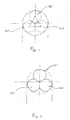
- the section of the strands is squeezed, and is substantially changed from the section as shown in Fig. 1, in which the strands 101, 102, 103 are simply side-by-side, to a section as shown in Fig. 2, in which the three strands have contact lines and are squeezed both along the outer edges and along the contact edges.
- hammering is effected at two or more concave surfaces, forming as many sectors of a circle, and acting in a radial direction, which surfaces form together a substantially circular surface.
- the three strands or wires are covered with the jacket 2, as shown in Fig. 3, in the particular preferred embodiment of a three strand cable.
- All the figures show a preferred embodiment in which the strands or wires are three in number, have the same diameter, and are helically wound to form the cable, but they can be provided in a greater number, though within certain limits, so as to have a small number of lines of contact with the sheath.
- the cable of this invention is particularly useful for all applications in which the relative motion between the cable and the sheath is particularly frequent, e.g. in steering devices and devices for transmitting frequently varying driving signals.
- the wear of conventional cables is particularly critical, and involves the provision of further oversizing and extra-lubrication, whereas lubrication in the inventive cable is optimized thanks to the lubricant distribution provided by the helical paddles formed by the fronts of the helical chambers as mentioned above.
- the respective centers of the circumferences of the strands or wires 101, 102, 103 are at the vertices of an equilateral triangle, as outlined in dashed lines, the center of gravity of such equilateral triangle corresponding to the longitudinal winding axis of the helicoid formed by the three strands or wires.
- Fig. 3 shows the cable of the present invention when used in combination with a sheath 3 whose inside diameter is about equal to the diameter of the cylindrical envelope defined by the cross section of the cable 1.
- the sheath 3 and the cable 1 have three lines of contact with each other, whose extension is substantially smaller than in prior art cables.
- the section thereof approximates a circumference, therefore a great number of points of contact exist between the cable and the sheath, which causes a high friction and wear.
- the cable of this invention provides a substantially lower friction than prior art cables and affords the advantages as described above.
- a chamber is formed between two adjacent wires and the inner surface of the sheath 3, which chamber extends in a helical arrangement along the cable and is referred to as helical chamber 4, as shown in Fig. 4.
- at least one of said helical chambers 4 may be arranged to contain or be supplied with a fluid lubricant 5, as shown in Fig. 6.
- the covered surface of each strand or wire, facing toward the corresponding helical chamber acts as a feeding/spreading surface 401 for the fluid lubricant 5 contained in the associated helical chamber 4. Therefore, due to the relative motion between said cable 1 and said sheath 3, each helical chamber 4 containing said fluid lubricant acts as a chamber for pumping/distributing the fluid lubricant along the cable.
- the inventive cable obviates prior art drawbacks, involving the use of better or oversized materials as compared with actual application requirements. Indeed, thanks to its lower friction, the cable of the invention allows to strictly use the materials and sizes that are determined by typical calculations related to the ability to exceed the mechanical stress, without substantially requiring any oversizing for wear resistance.
- the cable of this invention may be comprised of such a number of strands or wires as to include, for every cross section, a small number of lines of contact with the associated sheath, and peripheral helical chambers for housing/distributing lubricant as well as helical surfaces for feeding/distributing said lubricant.
- the strands will be helically wound to form fluid lubricant distribution chambers, delimited by the facing peripheral surface fronts of strands, whose radial depths, with respect to the maximum radius of the cylindrical envelope of the cable are such that said peripheral surface fronts face substantially forward with reference to a cable sliding direction, and form convex helical paddles for distributing the lubricant between the points of tangency of the cable and the inner surface of the sheath.
- Said helical paddle fronts so generated are convex and proportionally get closer to the sheath surface while exerting a compression force on the fluid lubricant as the cable slides inside the sheath.
- the fronts extend along a portion of the whole radius of the inner cavity of the sheath and/or of the maximum radius of the cavity: from a maximum 50% to a minimum 10% of said maximum radius of the cavity and/or the radius of the cylindrical envelope defined by the cross section of the cable, as shown in the three-strand or wire arrangement in Fig. 6. More generally, these helical chambers are in the same number as the strands or wires of the cable.
- the strands or wires may have different diameters.
- the fluid lubricant 5 may further have a cooling effect, for removing the heat generated by friction and/or help to remove the wear material built up in said chambers.
Landscapes
- Engineering & Computer Science (AREA)
- General Engineering & Computer Science (AREA)
- Health & Medical Sciences (AREA)
- Oral & Maxillofacial Surgery (AREA)
- Mechanical Engineering (AREA)
- Insulated Conductors (AREA)
- Flexible Shafts (AREA)
Applications Claiming Priority (2)
| Application Number | Priority Date | Filing Date | Title |
|---|---|---|---|
| IT000001A ITSV20040001A1 (it) | 2004-01-12 | 2004-01-12 | Cavo multifilamento elicoidale in particolare per la trasmissione mecc anica di movimento |
| ITSV20040001 | 2004-01-12 |
Publications (3)
| Publication Number | Publication Date |
|---|---|
| EP1553226A2 true EP1553226A2 (de) | 2005-07-13 |
| EP1553226A3 EP1553226A3 (de) | 2007-03-21 |
| EP1553226B1 EP1553226B1 (de) | 2016-04-13 |
Family
ID=34587011
Family Applications (1)
| Application Number | Title | Priority Date | Filing Date |
|---|---|---|---|
| EP04107065.7A Expired - Lifetime EP1553226B1 (de) | 2004-01-12 | 2004-12-30 | Verfahren zur Herstellung eines Kabels sowie nach diesem Verfahren hergestelltes Kabel |
Country Status (3)
| Country | Link |
|---|---|
| US (1) | US7197809B2 (de) |
| EP (1) | EP1553226B1 (de) |
| IT (1) | ITSV20040001A1 (de) |
Cited By (4)
| Publication number | Priority date | Publication date | Assignee | Title |
|---|---|---|---|---|
| EP1938182A4 (de) * | 2005-05-20 | 2010-02-24 | Teleflex Inc | Push-pull-kabel und herstellungsverfahren dafür |
| DE102011053795A1 (de) | 2011-09-20 | 2013-03-21 | Küster Holding GmbH | Seilzug, insbesondere für einen Fensterheber |
| IT201700037789A1 (it) * | 2017-04-06 | 2018-10-06 | Ultraflex Spa | Sonda passacavi o per elementi flessibili simili |
| IT201800021154A1 (it) | 2018-12-27 | 2020-06-27 | I L Ind Di Leivi S R L | Sonda passacavi o per elementi flessibili simili |
Families Citing this family (11)
| Publication number | Priority date | Publication date | Assignee | Title |
|---|---|---|---|---|
| US10763008B2 (en) | 2004-09-28 | 2020-09-01 | Southwire Company, Llc | Method of manufacturing electrical cable, and resulting product, with reduced required installation pulling force |
| US7749024B2 (en) | 2004-09-28 | 2010-07-06 | Southwire Company | Method of manufacturing THHN electrical cable, and resulting product, with reduced required installation pulling force |
| US20100116084A1 (en) * | 2008-11-10 | 2010-05-13 | Cable Manufacturing & Assembly, Inc. | Liner and cable construction |
| US8986586B2 (en) | 2009-03-18 | 2015-03-24 | Southwire Company, Llc | Electrical cable having crosslinked insulation with internal pulling lubricant |
| ITGE20110146A1 (it) | 2011-12-23 | 2013-06-24 | Ultraflex Spa | Timoneria per imbarcazioni |
| DE102012112911A1 (de) * | 2012-12-21 | 2014-06-26 | Casar Drahtseilwerk Saar Gmbh | Drahtseil sowie Verfahren und Vorrichtung zur Herstellung des Drahtseils |
| US10431350B1 (en) | 2015-02-12 | 2019-10-01 | Southwire Company, Llc | Non-circular electrical cable having a reduced pulling force |
| EP3211642A1 (de) * | 2016-02-23 | 2017-08-30 | LEONI Kabel Holding GmbH | Datenkabel und litzenleiter |
| TWI724839B (zh) * | 2019-04-16 | 2021-04-11 | 謝佳璋 | 導電線纜的製造方法 |
| CN114284002B (zh) * | 2021-12-23 | 2023-06-23 | 苏州君思琦线缆科技有限公司 | 一种带有冷却润滑装置的电缆生产用绞线机 |
| CN119158163B (zh) * | 2023-06-19 | 2026-04-03 | 上海心恒睿医疗科技有限公司 | 经皮心室辅助装置 |
Citations (1)
| Publication number | Priority date | Publication date | Assignee | Title |
|---|---|---|---|---|
| FR2606046A1 (fr) | 1986-10-29 | 1988-05-06 | Sefi Soc Europ Fab Ind | Cable de commande a distance |
Family Cites Families (23)
| Publication number | Priority date | Publication date | Assignee | Title |
|---|---|---|---|---|
| US251114A (en) * | 1881-12-20 | Wire rope and cable | ||
| FR766758A (de) * | 1933-05-25 | 1934-07-03 | ||
| DE1067343B (de) * | 1953-11-18 | |||
| NL110290C (de) * | 1954-08-13 | |||
| AT207202B (de) * | 1959-01-08 | 1960-01-25 | Fertigungstechnik U Maschb Ges | Schmiedemaschine |
| US3131469A (en) * | 1960-03-21 | 1964-05-05 | Tyler Wayne Res Corp | Process of producing a unitary multiple wire strand |
| US3130536A (en) * | 1961-09-21 | 1964-04-28 | American Chain & Cable Co | Method of manufacturing wire rope |
| US3234722A (en) * | 1963-04-12 | 1966-02-15 | American Chain & Cable Co | Compacted stranded cable |
| US3257863A (en) * | 1963-08-12 | 1966-06-28 | Teleflex Inc | Cable construction |
| US3355544A (en) * | 1965-02-24 | 1967-11-28 | Vivian G Costley | Small diameter high tensile strength coaxial electrical cable |
| US3383704A (en) * | 1967-01-10 | 1968-05-14 | Southwire Co | Multistrand cable |
| US3823542A (en) * | 1972-04-14 | 1974-07-16 | Anaconda Co | Method of making compact conductor |
| US4311001A (en) * | 1978-12-08 | 1982-01-19 | Glushko Mikhail F | Method for manufacturing twisted wire products and product made by this method |
| US4722216A (en) * | 1982-02-08 | 1988-02-02 | Grotnes Metalforming Systems, Inc. | Radial forging method |
| RU2008994C1 (ru) * | 1992-06-04 | 1994-03-15 | Тюрин Валерий Александрович | Способ радиальной ковки |
| US5449861A (en) * | 1993-02-24 | 1995-09-12 | Vazaki Corporation | Wire for press-connecting terminal and method of producing the conductive wire |
| US6137060A (en) * | 1997-05-02 | 2000-10-24 | General Science And Technology Corp | Multifilament drawn radiopaque highly elastic cables and methods of making the same |
| US6449834B1 (en) * | 1997-05-02 | 2002-09-17 | Scilogy Corp. | Electrical conductor coils and methods of making same |
| US6313409B1 (en) * | 1997-05-02 | 2001-11-06 | General Science And Technology Corp | Electrical conductors and methods of making same |
| DE19811178C1 (de) * | 1998-03-14 | 1999-09-09 | Stihl Maschf Andreas | Handgeführtes Arbeitsgerät mit einer fettgeschmierten Antriebswelle |
| AT408852B (de) * | 2000-06-23 | 2002-03-25 | Gfm Beteiligungs & Man Gmbh | Verfahren zum schmieden eines metallenen werkstückes |
| DE10150999C2 (de) * | 2001-10-16 | 2003-08-07 | Peak Werkstoff Gmbh | Verfahren zum Profilieren der äußeren Umfangsfläche von Zylinderlaufbuchsen |
| RU2220020C1 (ru) * | 2002-04-04 | 2003-12-27 | Открытое акционерное общество "Чепецкий механический завод" | Способ изготовления поковок преимущественно из металлов и сплавов подгруппы титана и ковочный комплекс для его осуществления |
-
2004
- 2004-01-12 IT IT000001A patent/ITSV20040001A1/it unknown
- 2004-12-30 EP EP04107065.7A patent/EP1553226B1/de not_active Expired - Lifetime
-
2005
- 2005-01-12 US US11/033,978 patent/US7197809B2/en not_active Expired - Lifetime
Patent Citations (1)
| Publication number | Priority date | Publication date | Assignee | Title |
|---|---|---|---|---|
| FR2606046A1 (fr) | 1986-10-29 | 1988-05-06 | Sefi Soc Europ Fab Ind | Cable de commande a distance |
Cited By (7)
| Publication number | Priority date | Publication date | Assignee | Title |
|---|---|---|---|---|
| EP1938182A4 (de) * | 2005-05-20 | 2010-02-24 | Teleflex Inc | Push-pull-kabel und herstellungsverfahren dafür |
| DE102011053795A1 (de) | 2011-09-20 | 2013-03-21 | Küster Holding GmbH | Seilzug, insbesondere für einen Fensterheber |
| DE102011053795B4 (de) | 2011-09-20 | 2018-03-01 | Küster Holding GmbH | Seilzug eines Fensterhebers, Kraftübertragungsvorrichtung, Fensterheber und Kraftfahrzeug |
| IT201700037789A1 (it) * | 2017-04-06 | 2018-10-06 | Ultraflex Spa | Sonda passacavi o per elementi flessibili simili |
| EP3386047A1 (de) * | 2017-04-06 | 2018-10-10 | Ultraflex Spa | Kabel-einziehband |
| US10801160B2 (en) | 2017-04-06 | 2020-10-13 | Ultraflex S.P.A. | Draw tape for cables or similar flexible elements |
| IT201800021154A1 (it) | 2018-12-27 | 2020-06-27 | I L Ind Di Leivi S R L | Sonda passacavi o per elementi flessibili simili |
Also Published As
| Publication number | Publication date |
|---|---|
| ITSV20040001A1 (it) | 2004-04-12 |
| US7197809B2 (en) | 2007-04-03 |
| EP1553226A3 (de) | 2007-03-21 |
| EP1553226B1 (de) | 2016-04-13 |
| US20060032661A1 (en) | 2006-02-16 |
Similar Documents
| Publication | Publication Date | Title |
|---|---|---|
| US7197809B2 (en) | Method for fabricating an helical stranded cable, particularly for mechanical motion transmission, and cable produced by that method | |
| US3481156A (en) | Power transmission assembly | |
| CA1199082A (en) | Oil well cable | |
| US20010000854A1 (en) | Push-pull control cable | |
| US3214995A (en) | Push-pull cable with plastic lined casing | |
| FI60765B (fi) | Hylsa foer anvaendning pao staolvajer eller -parter | |
| EP0146617A1 (de) | Riemenquerelement und riemenaufbau fuer ein stufenloses regelbares getriebe. | |
| CN102678732A (zh) | 一种汽车拉索套管 | |
| US4454377A (en) | Oil well cable | |
| EP0896087A1 (de) | Drahtseil mit einem metallischen Kernseil | |
| US3460578A (en) | Composite flexible shaft casing | |
| EP0376180B1 (de) | Steuerseil | |
| US8827820B1 (en) | Flexible shaft with interference fit capability | |
| CN105240533B (zh) | 密封环 | |
| US3257863A (en) | Cable construction | |
| DE102008019786B3 (de) | Betätigungszug mit kunststoffummanteltem Innenzug | |
| JP5325889B2 (ja) | 高負荷伝動用vベルト | |
| US3135131A (en) | Push-pull cable construction | |
| US2087373A (en) | Conduit | |
| US10801160B2 (en) | Draw tape for cables or similar flexible elements | |
| CN110753672B (zh) | 用作电梯牵引绳的缆绳 | |
| WO2001092757A1 (de) | Keilriemen zur verlustarmen leistungsübertragung | |
| KR100264408B1 (ko) | 별도의 와이어 로우프 코아를 가진 와이어 로우프 | |
| US5494104A (en) | Snap-on rod guide | |
| JP2004019732A (ja) | インナーケーブルおよびそれを用いたコントロールケーブル |
Legal Events
| Date | Code | Title | Description |
|---|---|---|---|
| PUAI | Public reference made under article 153(3) epc to a published international application that has entered the european phase |
Free format text: ORIGINAL CODE: 0009012 |
|
| AK | Designated contracting states |
Kind code of ref document: A2 Designated state(s): AT BE BG CH CY CZ DE DK EE ES FI FR GB GR HU IE IS IT LI LT LU MC NL PL PT RO SE SI SK TR |
|
| AX | Request for extension of the european patent |
Extension state: AL BA HR LV MK YU |
|
| PUAL | Search report despatched |
Free format text: ORIGINAL CODE: 0009013 |
|
| AK | Designated contracting states |
Kind code of ref document: A3 Designated state(s): AT BE BG CH CY CZ DE DK EE ES FI FR GB GR HU IE IS IT LI LT LU MC NL PL PT RO SE SI SK TR |
|
| AX | Request for extension of the european patent |
Extension state: AL BA HR LV MK YU |
|
| 17P | Request for examination filed |
Effective date: 20070822 |
|
| AKX | Designation fees paid |
Designated state(s): AT BE BG CH CY CZ DE DK EE ES FI FR GB GR HU IE IS IT LI LT LU MC NL PL PT RO SE SI SK TR |
|
| 17Q | First examination report despatched |
Effective date: 20110401 |
|
| GRAP | Despatch of communication of intention to grant a patent |
Free format text: ORIGINAL CODE: EPIDOSNIGR1 |
|
| INTG | Intention to grant announced |
Effective date: 20151027 |
|
| GRAS | Grant fee paid |
Free format text: ORIGINAL CODE: EPIDOSNIGR3 |
|
| GRAA | (expected) grant |
Free format text: ORIGINAL CODE: 0009210 |
|
| AK | Designated contracting states |
Kind code of ref document: B1 Designated state(s): AT BE BG CH CY CZ DE DK EE ES FI FR GB GR HU IE IS IT LI LT LU MC NL PL PT RO SE SI SK TR |
|
| REG | Reference to a national code |
Ref country code: GB Ref legal event code: FG4D |
|
| REG | Reference to a national code |
Ref country code: AT Ref legal event code: REF Ref document number: 790300 Country of ref document: AT Kind code of ref document: T Effective date: 20160415 Ref country code: CH Ref legal event code: EP |
|
| REG | Reference to a national code |
Ref country code: IE Ref legal event code: FG4D |
|
| REG | Reference to a national code |
Ref country code: DE Ref legal event code: R096 Ref document number: 602004049026 Country of ref document: DE |
|
| REG | Reference to a national code |
Ref country code: LT Ref legal event code: MG4D |
|
| REG | Reference to a national code |
Ref country code: AT Ref legal event code: MK05 Ref document number: 790300 Country of ref document: AT Kind code of ref document: T Effective date: 20160413 |
|
| REG | Reference to a national code |
Ref country code: NL Ref legal event code: MP Effective date: 20160413 |
|
| PG25 | Lapsed in a contracting state [announced via postgrant information from national office to epo] |
Ref country code: LT Free format text: LAPSE BECAUSE OF FAILURE TO SUBMIT A TRANSLATION OF THE DESCRIPTION OR TO PAY THE FEE WITHIN THE PRESCRIBED TIME-LIMIT Effective date: 20160413 Ref country code: FI Free format text: LAPSE BECAUSE OF FAILURE TO SUBMIT A TRANSLATION OF THE DESCRIPTION OR TO PAY THE FEE WITHIN THE PRESCRIBED TIME-LIMIT Effective date: 20160413 Ref country code: PL Free format text: LAPSE BECAUSE OF FAILURE TO SUBMIT A TRANSLATION OF THE DESCRIPTION OR TO PAY THE FEE WITHIN THE PRESCRIBED TIME-LIMIT Effective date: 20160413 Ref country code: NL Free format text: LAPSE BECAUSE OF FAILURE TO SUBMIT A TRANSLATION OF THE DESCRIPTION OR TO PAY THE FEE WITHIN THE PRESCRIBED TIME-LIMIT Effective date: 20160413 |
|
| REG | Reference to a national code |
Ref country code: FR Ref legal event code: PLFP Year of fee payment: 13 |
|
| PG25 | Lapsed in a contracting state [announced via postgrant information from national office to epo] |
Ref country code: PT Free format text: LAPSE BECAUSE OF FAILURE TO SUBMIT A TRANSLATION OF THE DESCRIPTION OR TO PAY THE FEE WITHIN THE PRESCRIBED TIME-LIMIT Effective date: 20160816 Ref country code: GR Free format text: LAPSE BECAUSE OF FAILURE TO SUBMIT A TRANSLATION OF THE DESCRIPTION OR TO PAY THE FEE WITHIN THE PRESCRIBED TIME-LIMIT Effective date: 20160714 Ref country code: AT Free format text: LAPSE BECAUSE OF FAILURE TO SUBMIT A TRANSLATION OF THE DESCRIPTION OR TO PAY THE FEE WITHIN THE PRESCRIBED TIME-LIMIT Effective date: 20160413 Ref country code: ES Free format text: LAPSE BECAUSE OF FAILURE TO SUBMIT A TRANSLATION OF THE DESCRIPTION OR TO PAY THE FEE WITHIN THE PRESCRIBED TIME-LIMIT Effective date: 20160413 Ref country code: SE Free format text: LAPSE BECAUSE OF FAILURE TO SUBMIT A TRANSLATION OF THE DESCRIPTION OR TO PAY THE FEE WITHIN THE PRESCRIBED TIME-LIMIT Effective date: 20160413 |
|
| PG25 | Lapsed in a contracting state [announced via postgrant information from national office to epo] |
Ref country code: IT Free format text: LAPSE BECAUSE OF FAILURE TO SUBMIT A TRANSLATION OF THE DESCRIPTION OR TO PAY THE FEE WITHIN THE PRESCRIBED TIME-LIMIT Effective date: 20160413 Ref country code: BE Free format text: LAPSE BECAUSE OF FAILURE TO SUBMIT A TRANSLATION OF THE DESCRIPTION OR TO PAY THE FEE WITHIN THE PRESCRIBED TIME-LIMIT Effective date: 20160413 |
|
| REG | Reference to a national code |
Ref country code: DE Ref legal event code: R097 Ref document number: 602004049026 Country of ref document: DE |
|
| PG25 | Lapsed in a contracting state [announced via postgrant information from national office to epo] |
Ref country code: SK Free format text: LAPSE BECAUSE OF FAILURE TO SUBMIT A TRANSLATION OF THE DESCRIPTION OR TO PAY THE FEE WITHIN THE PRESCRIBED TIME-LIMIT Effective date: 20160413 Ref country code: RO Free format text: LAPSE BECAUSE OF FAILURE TO SUBMIT A TRANSLATION OF THE DESCRIPTION OR TO PAY THE FEE WITHIN THE PRESCRIBED TIME-LIMIT Effective date: 20160413 Ref country code: EE Free format text: LAPSE BECAUSE OF FAILURE TO SUBMIT A TRANSLATION OF THE DESCRIPTION OR TO PAY THE FEE WITHIN THE PRESCRIBED TIME-LIMIT Effective date: 20160413 Ref country code: CZ Free format text: LAPSE BECAUSE OF FAILURE TO SUBMIT A TRANSLATION OF THE DESCRIPTION OR TO PAY THE FEE WITHIN THE PRESCRIBED TIME-LIMIT Effective date: 20160413 Ref country code: DK Free format text: LAPSE BECAUSE OF FAILURE TO SUBMIT A TRANSLATION OF THE DESCRIPTION OR TO PAY THE FEE WITHIN THE PRESCRIBED TIME-LIMIT Effective date: 20160413 |
|
| PLBE | No opposition filed within time limit |
Free format text: ORIGINAL CODE: 0009261 |
|
| STAA | Information on the status of an ep patent application or granted ep patent |
Free format text: STATUS: NO OPPOSITION FILED WITHIN TIME LIMIT |
|
| 26N | No opposition filed |
Effective date: 20170116 |
|
| PG25 | Lapsed in a contracting state [announced via postgrant information from national office to epo] |
Ref country code: SI Free format text: LAPSE BECAUSE OF FAILURE TO SUBMIT A TRANSLATION OF THE DESCRIPTION OR TO PAY THE FEE WITHIN THE PRESCRIBED TIME-LIMIT Effective date: 20160413 |
|
| PG25 | Lapsed in a contracting state [announced via postgrant information from national office to epo] |
Ref country code: MC Free format text: LAPSE BECAUSE OF FAILURE TO SUBMIT A TRANSLATION OF THE DESCRIPTION OR TO PAY THE FEE WITHIN THE PRESCRIBED TIME-LIMIT Effective date: 20160413 |
|
| REG | Reference to a national code |
Ref country code: IE Ref legal event code: MM4A |
|
| PG25 | Lapsed in a contracting state [announced via postgrant information from national office to epo] |
Ref country code: LU Free format text: LAPSE BECAUSE OF NON-PAYMENT OF DUE FEES Effective date: 20161230 |
|
| PG25 | Lapsed in a contracting state [announced via postgrant information from national office to epo] |
Ref country code: IE Free format text: LAPSE BECAUSE OF NON-PAYMENT OF DUE FEES Effective date: 20161230 |
|
| REG | Reference to a national code |
Ref country code: FR Ref legal event code: PLFP Year of fee payment: 14 |
|
| PG25 | Lapsed in a contracting state [announced via postgrant information from national office to epo] |
Ref country code: CY Free format text: LAPSE BECAUSE OF FAILURE TO SUBMIT A TRANSLATION OF THE DESCRIPTION OR TO PAY THE FEE WITHIN THE PRESCRIBED TIME-LIMIT Effective date: 20160413 Ref country code: HU Free format text: LAPSE BECAUSE OF FAILURE TO SUBMIT A TRANSLATION OF THE DESCRIPTION OR TO PAY THE FEE WITHIN THE PRESCRIBED TIME-LIMIT; INVALID AB INITIO Effective date: 20041230 |
|
| PG25 | Lapsed in a contracting state [announced via postgrant information from national office to epo] |
Ref country code: IS Free format text: LAPSE BECAUSE OF FAILURE TO SUBMIT A TRANSLATION OF THE DESCRIPTION OR TO PAY THE FEE WITHIN THE PRESCRIBED TIME-LIMIT Effective date: 20160413 Ref country code: TR Free format text: LAPSE BECAUSE OF FAILURE TO SUBMIT A TRANSLATION OF THE DESCRIPTION OR TO PAY THE FEE WITHIN THE PRESCRIBED TIME-LIMIT Effective date: 20160413 |
|
| PG25 | Lapsed in a contracting state [announced via postgrant information from national office to epo] |
Ref country code: BG Free format text: LAPSE BECAUSE OF FAILURE TO SUBMIT A TRANSLATION OF THE DESCRIPTION OR TO PAY THE FEE WITHIN THE PRESCRIBED TIME-LIMIT Effective date: 20160413 |
|
| PGFP | Annual fee paid to national office [announced via postgrant information from national office to epo] |
Ref country code: GB Payment date: 20231124 Year of fee payment: 20 |
|
| PGFP | Annual fee paid to national office [announced via postgrant information from national office to epo] |
Ref country code: FR Payment date: 20231124 Year of fee payment: 20 Ref country code: DE Payment date: 20231206 Year of fee payment: 20 |
|
| PGFP | Annual fee paid to national office [announced via postgrant information from national office to epo] |
Ref country code: CH Payment date: 20240101 Year of fee payment: 20 |
|
| REG | Reference to a national code |
Ref country code: CH Ref legal event code: PL Ref country code: DE Ref legal event code: R071 Ref document number: 602004049026 Country of ref document: DE |
|
| PG25 | Lapsed in a contracting state [announced via postgrant information from national office to epo] |
Ref country code: GB Free format text: LAPSE BECAUSE OF EXPIRATION OF PROTECTION Effective date: 20241229 |
|
| REG | Reference to a national code |
Ref country code: GB Ref legal event code: PE20 Expiry date: 20241229 |
|
| PG25 | Lapsed in a contracting state [announced via postgrant information from national office to epo] |
Ref country code: GB Free format text: LAPSE BECAUSE OF EXPIRATION OF PROTECTION Effective date: 20241229 |