EP1553003A2 - Teleskopierende Lenksäule mit Bremse - Google Patents
Teleskopierende Lenksäule mit Bremse Download PDFInfo
- Publication number
- EP1553003A2 EP1553003A2 EP04078470A EP04078470A EP1553003A2 EP 1553003 A2 EP1553003 A2 EP 1553003A2 EP 04078470 A EP04078470 A EP 04078470A EP 04078470 A EP04078470 A EP 04078470A EP 1553003 A2 EP1553003 A2 EP 1553003A2
- Authority
- EP
- European Patent Office
- Prior art keywords
- brake
- jacket
- upper jacket
- steering column
- walls
- Prior art date
- Legal status (The legal status is an assumption and is not a legal conclusion. Google has not performed a legal analysis and makes no representation as to the accuracy of the status listed.)
- Granted
Links
- 230000000295 complement effect Effects 0.000 claims description 2
- 230000000712 assembly Effects 0.000 description 1
- 238000000429 assembly Methods 0.000 description 1
- 238000012986 modification Methods 0.000 description 1
- 230000004048 modification Effects 0.000 description 1
Images


Classifications
-
- B—PERFORMING OPERATIONS; TRANSPORTING
- B62—LAND VEHICLES FOR TRAVELLING OTHERWISE THAN ON RAILS
- B62D—MOTOR VEHICLES; TRAILERS
- B62D1/00—Steering controls, i.e. means for initiating a change of direction of the vehicle
- B62D1/02—Steering controls, i.e. means for initiating a change of direction of the vehicle vehicle-mounted
- B62D1/16—Steering columns
- B62D1/18—Steering columns yieldable or adjustable, e.g. tiltable
- B62D1/184—Mechanisms for locking columns at selected positions
Definitions
- the subject invention relates to a vehicle steering column of the type having telescoping jackets to adjust the position of a steering wheel connected to the vehicle steering column to accommodate the driver.
- a telescoping steering column assembly typically uses two jackets, wherein one jacket is fixed to a frame of a vehicle body, and the other jacket is adapted to be translated with respect to the jacket fixed to the frame, thereby providing relative longitudinal movement between the two jackets with respect to one another.
- These jackets engaged one within the other in a telescoping fashion, allow the driver to push or pull the steering wheel to a desired position and then to lock the telescoping column.
- Another prior art design includes a locking mechanism with a pad and a locking bolt to abut the pad and to displace the pad in a lateral direction to lock the jackets engaged one within the other in the telescoping fashion.
- the locking mechanism requires expensive multi-lead thread for both the locking bolt (male thread) and one of the jackets (female thread) in order to provide a mechanical engagement between the pad and the locking bolt and to move the locking bolt inwardly to and outwardly from the pad in operation of the locking mechanism.
- this locking mechanism includes a boss section integral with and extending outwardly from the side of the jacket thereby increasing a size of the telescoping steering column assembly.
- a telescoping steering column assembly of the present invention includes an upper jacket, a lower jacket disposed in telescoping relationship within the upper jacket along a longitudinal axis, and a brake supported by the upper jacket for frictional engagement with the lower jacket.
- the telescoping steering column assembly includes a cam device for moving the brake into frictional engagement with the lower jacket.
- the brake presents an inclined surface sloping longitudinally of the jackets with the cam device rotatable into and out of engagement with the inclined surface.
- An advantage of the present invention is to provide the brake with inclined surface that maintains proper frictional engagement between the upper and lower jackets.
- Another advantage of the present invention is to provide a locking mechanism having all components symmetrically mounted on the bottom of the fixed jacket thereby contributing to the compactness of the assembly.
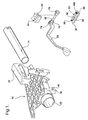
- a telescoping steering column assembly of the present invention is generally shown at 10 .
- the telescoping steering column assembly 10 includes a upper jacket, generally indicated at 12 , a lower jacket 14 , disposed in telescoping relationship within the upper jacket 12 along a longitudinal axes A, and a brake, generally indicated at 16, supported by the upper jacket 12 for frictional engagement with the lower jacket 14.
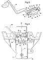
- the telescoping steering column assembly 10 includes a cam device, generally indicated at 18 , for moving the brake 16 into frictional engagement with the lower jacket 14 , shown in Figures 2 and 3.
- the brake 16 presents an inclined surface 20 sloping longitudinally of the jackets 12, 14 with the cam device 18 rotatable into and out of engagement with the inclined surface 20 .
- the upper jacket 12 of the present invention includes a body 22 having leading 24 and trailing 26 ends and opening 28 of a generally circular configuration as viewed in cross section.
- the opening 28 extends axially from the leading 24 to the trailing 26 ends of the upper jacket 12 .
- the upper jacket 12 includes a cavity 30 of a generally rectangular configuration, defined within the body 22 at the leading end 24 .
- the upper jacket 12 further includes at least one integral projection 32 extending from the body 22 to the opening 28 and two walls 34, 36 integral with and spaced from one the other and extending downwardly from the body 22 of the upper jacket 12 at the leading end 24 .
- Each walls 34, 36 includes a hole 38, 40, respectively, of a generally circular configuration aligned with respect to one the other.
- the brake 16 is supported between the walls 34, 36 and extends through the cavity 30 defined within the body 22 to react with the lower jacket 14 and to force the lower jacket 14 into engagement with the upper jacket 12 to prevent relative longitudinal movements between the jackets 12 , 14 .
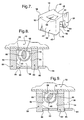
- the brake 16 includes top 41 , bottom 42 and side walls 44, 46, 48, and 50, as shown in Figure 7.
- the top 41 of the brake 16 includes a recess 52 complementary to the lower jacket 14 and a cavity 54 of a generally rectangular configuration defined within the top 41 .
- the bottom 42 of the brake 16 is further defined by a U-shaped opening, generally indicated at 56 , disposed horizontally between two of the side walls 46, 50 to divide the brake 16 into two sections, generally indicated at 58, 60, and separated by the U-shaped opening 56 .
- Each section 58, 60 includes an inner surface 62, 64, respectively, interconnected by the inclined surface 20 sloping longitudinally of the upper 12 and lower 14 jackets.
- the cam device 18 of the present invention includes a bar 66 extending through the walls 34, 36 and across the U-shaped opening 56 of the brake 16 .
- the bar 66 includes terminal ends 68, 70 of a generally circular configuration, as viewed in cross section, and a middle portion 72 of a generally elliptical configuration, as viewed in cross section, disposed between the terminal ends 68, 70 .
- the middle portion 72 of the bar 66 rotates against the inclined surface 20 of the brake 16 to move the brake 16 into frictional engagement with the lower jacket 14 .
- the cam device 18 includes bushings 74 , 76 disposed annularly about each of the terminal ends 68, 70 of the bar 66 .
- the cam device 18 includes a lever 80 attached to the bar 66 at one of the terminal ends 68 to rotate he bar 66 within the walls 34, 36 and the U-shaped opening 56 of the brake 16 and to move the brake 16 upwardly, to engage the lower jacket 14 with the upper jacket 12 , and downwardly, to disengage the jackets 12, 14 in different modes of operation of the assembly 10 .
- the telescoping steering column assembly 10 includes a plate, generally indicated at 82 , to hold the brake 16 within the walls 34, 36 of the upper jacket 12 .
- the plate 82 includes a generally rectangular configuration and has front 84, rear 86 and terminal ends 88, 90 .
- the plate 82 also includes an elongated slot 92, 94 at each of the terminal ends 88, 90 and a recess 96 of a generally rectangular configuration that extends between the elongated slots 92, 94 at the front 84 of the plate 82 .
- the recess 96 is designed to engage one of the sections 60 of the brake 16 , when the brake is retracted outwardly from the upper and lower jackets.
- the invention To connect the plate 82 to the upper jacket 12 , the invention includes a plurality of fasteners 98,100, as shown in Figures 2 and 3, extending through the elongated slots 92, 94 to connect the plate 82 to the upper jacket 12 , as best shown in Figure 4.
Landscapes
- Engineering & Computer Science (AREA)
- Chemical & Material Sciences (AREA)
- Combustion & Propulsion (AREA)
- Transportation (AREA)
- Mechanical Engineering (AREA)
- Steering Controls (AREA)
- Display Devices Of Pinball Game Machines (AREA)
- Braking Elements And Transmission Devices (AREA)
- Steering Devices For Bicycles And Motorcycles (AREA)
Applications Claiming Priority (2)
| Application Number | Priority Date | Filing Date | Title |
|---|---|---|---|
| US10/751,866 US7178832B2 (en) | 2004-01-06 | 2004-01-06 | Telescoping steering column assembly with brake |
| US751866 | 2004-01-06 |
Publications (3)
| Publication Number | Publication Date |
|---|---|
| EP1553003A2 true EP1553003A2 (de) | 2005-07-13 |
| EP1553003A3 EP1553003A3 (de) | 2005-09-21 |
| EP1553003B1 EP1553003B1 (de) | 2009-04-22 |
Family
ID=34592553
Family Applications (1)
| Application Number | Title | Priority Date | Filing Date |
|---|---|---|---|
| EP04078470A Expired - Lifetime EP1553003B1 (de) | 2004-01-06 | 2004-12-22 | Teleskopierende Lenksäule mit Bremse |
Country Status (4)
| Country | Link |
|---|---|
| US (1) | US7178832B2 (de) |
| EP (1) | EP1553003B1 (de) |
| AT (1) | ATE429372T1 (de) |
| DE (1) | DE602004020728D1 (de) |
Families Citing this family (5)
| Publication number | Priority date | Publication date | Assignee | Title |
|---|---|---|---|---|
| DE102004036585A1 (de) * | 2004-07-28 | 2006-03-23 | Robert Bosch Gmbh | Zwischenflansch für eine Werkzeugmaschine |
| JP5293737B2 (ja) * | 2008-06-24 | 2013-09-18 | 日本精工株式会社 | テレスコピックステアリング装置 |
| JP2016185719A (ja) * | 2015-03-27 | 2016-10-27 | 富士機工株式会社 | ステアリングコラム装置 |
| WO2017135384A1 (ja) * | 2016-02-04 | 2017-08-10 | 日本精工株式会社 | ステアリング装置 |
| GB2569124B (en) * | 2017-12-05 | 2022-05-11 | Trw Ltd | A steering column assembly |
Citations (8)
| Publication number | Priority date | Publication date | Assignee | Title |
|---|---|---|---|---|
| US5306032A (en) | 1992-03-04 | 1994-04-26 | Ecia-Equipements Et Composants Pour L'industrie Automobile | Adjustable steering column unit for an automobile vehicle |
| US5562307A (en) | 1994-07-29 | 1996-10-08 | The Torrington Company | Vehicle steering column adjustment and energy absorbing mechanism |
| US5700032A (en) | 1995-02-03 | 1997-12-23 | Nsk, Ltd. | Supporting apparatus for a steering column |
| US5743150A (en) | 1995-07-26 | 1998-04-28 | Lemforder Nacam S.A. | System for guiding and locking a motor vehicle steering column |
| US5845936A (en) | 1995-02-20 | 1998-12-08 | Nsk Ltd. | Collapsible outer column formed integral with brackets |
| US5927152A (en) | 1996-03-06 | 1999-07-27 | Lemforder Nacam | Device for preventing rotation of steering column body of an automobile vehicle |
| US5941129A (en) | 1997-07-21 | 1999-08-24 | General Motors Corporation | Clamp for motor vehicle steering column |
| US6450531B1 (en) | 2001-01-03 | 2002-09-17 | Daimlerchrysler Corporation | Anti-friction cam-operated friction disk clutch |
Family Cites Families (19)
| Publication number | Priority date | Publication date | Assignee | Title |
|---|---|---|---|---|
| US3491614A (en) | 1968-07-18 | 1970-01-27 | Bendix Corp | Collapsible steering column |
| US3955439A (en) * | 1974-09-30 | 1976-05-11 | Eaton Corporation | Positioning device for adjustable steering column |
| US4195535A (en) | 1978-01-23 | 1980-04-01 | Eaton Corporation | Positioning device for a vehicle steering column |
| US5148717A (en) | 1990-08-23 | 1992-09-22 | Nks Ltd. | Telescopic steering column apparatus |
| GB2263756A (en) * | 1992-01-24 | 1993-08-04 | Ford Motor Co | Adjustment mechanism for vehicle steering columns. |
| GB2281539A (en) * | 1993-09-01 | 1995-03-08 | Torrington Co | Adjustable vehicle steering column assembly |
| DE4413798C2 (de) | 1994-03-18 | 1996-09-12 | Porsche Ag | Verstellbare Lenkeinrichtung |
| US5570610A (en) | 1995-06-30 | 1996-11-05 | General Motors Corporation | Adjustable steering column |
| DE19524195C1 (de) | 1995-07-03 | 1996-10-31 | Daimler Benz Ag | Einstellvorrichtung zur Neigungsverstellung eines schwenkbar angelenkten Mantelrohres einer Lenkspindel eines Kraftfahrzeuges |
| KR0139454B1 (ko) * | 1995-10-18 | 1998-07-01 | 전성원 | 자동차의 조향축 마운트 구조 |
| DE19629246A1 (de) | 1996-07-19 | 1998-01-22 | Opel Adam Ag | Vorrichtung zur Verriegelung einer verstellbaren Lenksäule, insbesondere für Kraftfahrzeuge |
| US5979265A (en) | 1997-09-11 | 1999-11-09 | Mando Machinery Corporation | Tilting and telescopic structure for steering columns |
| DE19839527C2 (de) * | 1998-08-29 | 2000-07-27 | Daimler Chrysler Ag | Lenksäule für ein Kraftfahrzeug |
| US6139057A (en) | 1999-02-04 | 2000-10-31 | Delphi Technologies, Inc. | Position control apparatus for steering column |
| US6419269B1 (en) | 1999-09-20 | 2002-07-16 | Delphi Technologies | Locking system for adjustable position steering column |
| DE60133331T3 (de) | 2000-02-15 | 2012-12-06 | Nsk Ltd. | Lenkung für ein Automobil |
| US6357318B1 (en) | 2000-06-16 | 2002-03-19 | Trw Inc. | Steering column |
| JP2002067977A (ja) * | 2000-09-05 | 2002-03-08 | Fuji Kiko Co Ltd | テレスコピックステアリング装置 |
| GB0125673D0 (en) | 2001-10-25 | 2001-12-19 | Nsk Steering Sys Europ Ltd | Steering column clamping apparatus |
-
2004
- 2004-01-06 US US10/751,866 patent/US7178832B2/en not_active Expired - Fee Related
- 2004-12-22 AT AT04078470T patent/ATE429372T1/de not_active IP Right Cessation
- 2004-12-22 EP EP04078470A patent/EP1553003B1/de not_active Expired - Lifetime
- 2004-12-22 DE DE602004020728T patent/DE602004020728D1/de not_active Expired - Fee Related
Patent Citations (8)
| Publication number | Priority date | Publication date | Assignee | Title |
|---|---|---|---|---|
| US5306032A (en) | 1992-03-04 | 1994-04-26 | Ecia-Equipements Et Composants Pour L'industrie Automobile | Adjustable steering column unit for an automobile vehicle |
| US5562307A (en) | 1994-07-29 | 1996-10-08 | The Torrington Company | Vehicle steering column adjustment and energy absorbing mechanism |
| US5700032A (en) | 1995-02-03 | 1997-12-23 | Nsk, Ltd. | Supporting apparatus for a steering column |
| US5845936A (en) | 1995-02-20 | 1998-12-08 | Nsk Ltd. | Collapsible outer column formed integral with brackets |
| US5743150A (en) | 1995-07-26 | 1998-04-28 | Lemforder Nacam S.A. | System for guiding and locking a motor vehicle steering column |
| US5927152A (en) | 1996-03-06 | 1999-07-27 | Lemforder Nacam | Device for preventing rotation of steering column body of an automobile vehicle |
| US5941129A (en) | 1997-07-21 | 1999-08-24 | General Motors Corporation | Clamp for motor vehicle steering column |
| US6450531B1 (en) | 2001-01-03 | 2002-09-17 | Daimlerchrysler Corporation | Anti-friction cam-operated friction disk clutch |
Also Published As
| Publication number | Publication date |
|---|---|
| EP1553003A3 (de) | 2005-09-21 |
| US20050146124A1 (en) | 2005-07-07 |
| EP1553003B1 (de) | 2009-04-22 |
| US7178832B2 (en) | 2007-02-20 |
| DE602004020728D1 (de) | 2009-06-04 |
| ATE429372T1 (de) | 2009-05-15 |
Similar Documents
| Publication | Publication Date | Title |
|---|---|---|
| US6948741B2 (en) | Telescoping steering column assembly | |
| US8413541B2 (en) | Clamp assembly for a steering column assembly | |
| US8550420B2 (en) | Positively engaged locking system for a vehicle seat | |
| CN109435787B (zh) | 一种记忆模块以及带有易进入模块的座椅安装结构 | |
| US20030193180A1 (en) | Steering column for a vehicle | |
| US8641095B2 (en) | Steering column device | |
| US10099715B2 (en) | Stationary energy absorption strap control assembly for vehicle steering column | |
| EP1468895A1 (de) | Lenkvorrichtung | |
| EP2256015A2 (de) | Lenksäulenvorrichtung | |
| US7367589B2 (en) | Collapsible steering assembly with a stationary reaction surface | |
| CN102180108A (zh) | 座椅滑轨 | |
| CN102806939A (zh) | 转向装置 | |
| US10654513B2 (en) | Steering column assembly | |
| EP1083110A2 (de) | Drehender und verschiebender Energieaufnehmer für eine Lenksäule | |
| CN114802411A (zh) | 转向装置 | |
| US6260672B1 (en) | Vehicle seat with an adjusting mechanism | |
| US7178832B2 (en) | Telescoping steering column assembly with brake | |
| US7393014B2 (en) | Energy absorbing support for a vehicle steering assembly | |
| US20040251673A1 (en) | Tilt steering apparatus for vehicle | |
| JP2005014681A (ja) | 車両用ステアリングコラム装置 | |
| US9783220B2 (en) | Steering column assembly | |
| WO2011123091A1 (en) | Seat track assembly | |
| US5150871A (en) | Vehicle seat | |
| JP5360045B2 (ja) | ステアリングコラム用支持装置及びその組立方法 | |
| US20060266150A1 (en) | Clamp for friction lock mechanism on steering column |
Legal Events
| Date | Code | Title | Description |
|---|---|---|---|
| PUAI | Public reference made under article 153(3) epc to a published international application that has entered the european phase |
Free format text: ORIGINAL CODE: 0009012 |
|
| AK | Designated contracting states |
Kind code of ref document: A2 Designated state(s): AT BE BG CH CY CZ DE DK EE ES FI FR GB GR HU IE IS IT LI LT LU MC NL PL PT RO SE SI SK TR |
|
| AX | Request for extension of the european patent |
Extension state: AL BA HR LV MK YU |
|
| PUAL | Search report despatched |
Free format text: ORIGINAL CODE: 0009013 |
|
| AK | Designated contracting states |
Kind code of ref document: A3 Designated state(s): AT BE BG CH CY CZ DE DK EE ES FI FR GB GR HU IE IS IT LI LT LU MC NL PL PT RO SE SI SK TR |
|
| AX | Request for extension of the european patent |
Extension state: AL BA HR LV MK YU |
|
| 17P | Request for examination filed |
Effective date: 20060321 |
|
| AKX | Designation fees paid |
Designated state(s): AT BE BG CH CY CZ DE DK EE ES FI FR GB GR HU IE IS IT LI LT LU MC NL PL PT RO SE SI SK TR |
|
| 17Q | First examination report despatched |
Effective date: 20060905 |
|
| 17Q | First examination report despatched |
Effective date: 20060905 |
|
| GRAP | Despatch of communication of intention to grant a patent |
Free format text: ORIGINAL CODE: EPIDOSNIGR1 |
|
| GRAS | Grant fee paid |
Free format text: ORIGINAL CODE: EPIDOSNIGR3 |
|
| GRAA | (expected) grant |
Free format text: ORIGINAL CODE: 0009210 |
|
| AK | Designated contracting states |
Kind code of ref document: B1 Designated state(s): AT BE BG CH CY CZ DE DK EE ES FI FR GB GR HU IE IS IT LI LT LU MC NL PL PT RO SE SI SK TR |
|
| REG | Reference to a national code |
Ref country code: GB Ref legal event code: FG4D |
|
| REG | Reference to a national code |
Ref country code: CH Ref legal event code: EP |
|
| REG | Reference to a national code |
Ref country code: IE Ref legal event code: FG4D |
|
| REF | Corresponds to: |
Ref document number: 602004020728 Country of ref document: DE Date of ref document: 20090604 Kind code of ref document: P |
|
| NLV1 | Nl: lapsed or annulled due to failure to fulfill the requirements of art. 29p and 29m of the patents act | ||
| PG25 | Lapsed in a contracting state [announced via postgrant information from national office to epo] |
Ref country code: LT Free format text: LAPSE BECAUSE OF FAILURE TO SUBMIT A TRANSLATION OF THE DESCRIPTION OR TO PAY THE FEE WITHIN THE PRESCRIBED TIME-LIMIT Effective date: 20090422 Ref country code: AT Free format text: LAPSE BECAUSE OF FAILURE TO SUBMIT A TRANSLATION OF THE DESCRIPTION OR TO PAY THE FEE WITHIN THE PRESCRIBED TIME-LIMIT Effective date: 20090422 Ref country code: ES Free format text: LAPSE BECAUSE OF FAILURE TO SUBMIT A TRANSLATION OF THE DESCRIPTION OR TO PAY THE FEE WITHIN THE PRESCRIBED TIME-LIMIT Effective date: 20090802 Ref country code: FI Free format text: LAPSE BECAUSE OF FAILURE TO SUBMIT A TRANSLATION OF THE DESCRIPTION OR TO PAY THE FEE WITHIN THE PRESCRIBED TIME-LIMIT Effective date: 20090422 Ref country code: PT Free format text: LAPSE BECAUSE OF FAILURE TO SUBMIT A TRANSLATION OF THE DESCRIPTION OR TO PAY THE FEE WITHIN THE PRESCRIBED TIME-LIMIT Effective date: 20090822 |
|
| PG25 | Lapsed in a contracting state [announced via postgrant information from national office to epo] |
Ref country code: SE Free format text: LAPSE BECAUSE OF FAILURE TO SUBMIT A TRANSLATION OF THE DESCRIPTION OR TO PAY THE FEE WITHIN THE PRESCRIBED TIME-LIMIT Effective date: 20090722 Ref country code: SI Free format text: LAPSE BECAUSE OF FAILURE TO SUBMIT A TRANSLATION OF THE DESCRIPTION OR TO PAY THE FEE WITHIN THE PRESCRIBED TIME-LIMIT Effective date: 20090422 Ref country code: NL Free format text: LAPSE BECAUSE OF FAILURE TO SUBMIT A TRANSLATION OF THE DESCRIPTION OR TO PAY THE FEE WITHIN THE PRESCRIBED TIME-LIMIT Effective date: 20090422 Ref country code: PL Free format text: LAPSE BECAUSE OF FAILURE TO SUBMIT A TRANSLATION OF THE DESCRIPTION OR TO PAY THE FEE WITHIN THE PRESCRIBED TIME-LIMIT Effective date: 20090422 Ref country code: IS Free format text: LAPSE BECAUSE OF FAILURE TO SUBMIT A TRANSLATION OF THE DESCRIPTION OR TO PAY THE FEE WITHIN THE PRESCRIBED TIME-LIMIT Effective date: 20090822 |
|
| PG25 | Lapsed in a contracting state [announced via postgrant information from national office to epo] |
Ref country code: DK Free format text: LAPSE BECAUSE OF FAILURE TO SUBMIT A TRANSLATION OF THE DESCRIPTION OR TO PAY THE FEE WITHIN THE PRESCRIBED TIME-LIMIT Effective date: 20090422 Ref country code: RO Free format text: LAPSE BECAUSE OF FAILURE TO SUBMIT A TRANSLATION OF THE DESCRIPTION OR TO PAY THE FEE WITHIN THE PRESCRIBED TIME-LIMIT Effective date: 20090422 Ref country code: EE Free format text: LAPSE BECAUSE OF FAILURE TO SUBMIT A TRANSLATION OF THE DESCRIPTION OR TO PAY THE FEE WITHIN THE PRESCRIBED TIME-LIMIT Effective date: 20090422 Ref country code: CZ Free format text: LAPSE BECAUSE OF FAILURE TO SUBMIT A TRANSLATION OF THE DESCRIPTION OR TO PAY THE FEE WITHIN THE PRESCRIBED TIME-LIMIT Effective date: 20090422 |
|
| PG25 | Lapsed in a contracting state [announced via postgrant information from national office to epo] |
Ref country code: SK Free format text: LAPSE BECAUSE OF FAILURE TO SUBMIT A TRANSLATION OF THE DESCRIPTION OR TO PAY THE FEE WITHIN THE PRESCRIBED TIME-LIMIT Effective date: 20090422 Ref country code: BE Free format text: LAPSE BECAUSE OF FAILURE TO SUBMIT A TRANSLATION OF THE DESCRIPTION OR TO PAY THE FEE WITHIN THE PRESCRIBED TIME-LIMIT Effective date: 20090422 |
|
| PLBE | No opposition filed within time limit |
Free format text: ORIGINAL CODE: 0009261 |
|
| STAA | Information on the status of an ep patent application or granted ep patent |
Free format text: STATUS: NO OPPOSITION FILED WITHIN TIME LIMIT |
|
| 26N | No opposition filed |
Effective date: 20100125 |
|
| PG25 | Lapsed in a contracting state [announced via postgrant information from national office to epo] |
Ref country code: BG Free format text: LAPSE BECAUSE OF FAILURE TO SUBMIT A TRANSLATION OF THE DESCRIPTION OR TO PAY THE FEE WITHIN THE PRESCRIBED TIME-LIMIT Effective date: 20090722 |
|
| PG25 | Lapsed in a contracting state [announced via postgrant information from national office to epo] |
Ref country code: MC Free format text: LAPSE BECAUSE OF NON-PAYMENT OF DUE FEES Effective date: 20100701 |
|
| REG | Reference to a national code |
Ref country code: CH Ref legal event code: PL |
|
| GBPC | Gb: european patent ceased through non-payment of renewal fee |
Effective date: 20091222 |
|
| REG | Reference to a national code |
Ref country code: FR Ref legal event code: ST Effective date: 20100831 |
|
| REG | Reference to a national code |
Ref country code: IE Ref legal event code: MM4A |
|
| PG25 | Lapsed in a contracting state [announced via postgrant information from national office to epo] |
Ref country code: FR Free format text: LAPSE BECAUSE OF NON-PAYMENT OF DUE FEES Effective date: 20091231 Ref country code: CH Free format text: LAPSE BECAUSE OF NON-PAYMENT OF DUE FEES Effective date: 20091231 Ref country code: GR Free format text: LAPSE BECAUSE OF FAILURE TO SUBMIT A TRANSLATION OF THE DESCRIPTION OR TO PAY THE FEE WITHIN THE PRESCRIBED TIME-LIMIT Effective date: 20090723 Ref country code: IE Free format text: LAPSE BECAUSE OF NON-PAYMENT OF DUE FEES Effective date: 20091222 Ref country code: LI Free format text: LAPSE BECAUSE OF NON-PAYMENT OF DUE FEES Effective date: 20091231 |
|
| PG25 | Lapsed in a contracting state [announced via postgrant information from national office to epo] |
Ref country code: DE Free format text: LAPSE BECAUSE OF NON-PAYMENT OF DUE FEES Effective date: 20100701 |
|
| PG25 | Lapsed in a contracting state [announced via postgrant information from national office to epo] |
Ref country code: GB Free format text: LAPSE BECAUSE OF NON-PAYMENT OF DUE FEES Effective date: 20091222 |
|
| PG25 | Lapsed in a contracting state [announced via postgrant information from national office to epo] |
Ref country code: IT Free format text: LAPSE BECAUSE OF FAILURE TO SUBMIT A TRANSLATION OF THE DESCRIPTION OR TO PAY THE FEE WITHIN THE PRESCRIBED TIME-LIMIT Effective date: 20090422 |
|
| PG25 | Lapsed in a contracting state [announced via postgrant information from national office to epo] |
Ref country code: LU Free format text: LAPSE BECAUSE OF NON-PAYMENT OF DUE FEES Effective date: 20091222 |
|
| PG25 | Lapsed in a contracting state [announced via postgrant information from national office to epo] |
Ref country code: HU Free format text: LAPSE BECAUSE OF FAILURE TO SUBMIT A TRANSLATION OF THE DESCRIPTION OR TO PAY THE FEE WITHIN THE PRESCRIBED TIME-LIMIT Effective date: 20091023 |
|
| PG25 | Lapsed in a contracting state [announced via postgrant information from national office to epo] |
Ref country code: TR Free format text: LAPSE BECAUSE OF FAILURE TO SUBMIT A TRANSLATION OF THE DESCRIPTION OR TO PAY THE FEE WITHIN THE PRESCRIBED TIME-LIMIT Effective date: 20090422 |
|
| PG25 | Lapsed in a contracting state [announced via postgrant information from national office to epo] |
Ref country code: CY Free format text: LAPSE BECAUSE OF FAILURE TO SUBMIT A TRANSLATION OF THE DESCRIPTION OR TO PAY THE FEE WITHIN THE PRESCRIBED TIME-LIMIT Effective date: 20090422 |