EP1552900A1 - Welding method, welding system, and welding jig - Google Patents
Welding method, welding system, and welding jig Download PDFInfo
- Publication number
- EP1552900A1 EP1552900A1 EP03792679A EP03792679A EP1552900A1 EP 1552900 A1 EP1552900 A1 EP 1552900A1 EP 03792679 A EP03792679 A EP 03792679A EP 03792679 A EP03792679 A EP 03792679A EP 1552900 A1 EP1552900 A1 EP 1552900A1
- Authority
- EP
- European Patent Office
- Prior art keywords
- fuel tank
- welding
- attachments
- side panel
- outer side
- Prior art date
- Legal status (The legal status is an assumption and is not a legal conclusion. Google has not performed a legal analysis and makes no representation as to the accuracy of the status listed.)
- Granted
Links
Images


Classifications
-
- B—PERFORMING OPERATIONS; TRANSPORTING
- B23—MACHINE TOOLS; METAL-WORKING NOT OTHERWISE PROVIDED FOR
- B23K—SOLDERING OR UNSOLDERING; WELDING; CLADDING OR PLATING BY SOLDERING OR WELDING; CUTTING BY APPLYING HEAT LOCALLY, e.g. FLAME CUTTING; WORKING BY LASER BEAM
- B23K9/00—Arc welding or cutting
- B23K9/0026—Arc welding or cutting specially adapted for particular articles or work
-
- B—PERFORMING OPERATIONS; TRANSPORTING
- B23—MACHINE TOOLS; METAL-WORKING NOT OTHERWISE PROVIDED FOR
- B23K—SOLDERING OR UNSOLDERING; WELDING; CLADDING OR PLATING BY SOLDERING OR WELDING; CUTTING BY APPLYING HEAT LOCALLY, e.g. FLAME CUTTING; WORKING BY LASER BEAM
- B23K37/00—Auxiliary devices or processes, not specially adapted to a procedure covered by only one of the preceding main groups
- B23K37/04—Auxiliary devices or processes, not specially adapted to a procedure covered by only one of the preceding main groups for holding or positioning work
- B23K37/0426—Fixtures for other work
- B23K37/0435—Clamps
- B23K37/0443—Jigs
-
- B—PERFORMING OPERATIONS; TRANSPORTING
- B62—LAND VEHICLES FOR TRAVELLING OTHERWISE THAN ON RAILS
- B62J—CYCLE SADDLES OR SEATS; AUXILIARY DEVICES OR ACCESSORIES SPECIALLY ADAPTED TO CYCLES AND NOT OTHERWISE PROVIDED FOR, e.g. ARTICLE CARRIERS OR CYCLE PROTECTORS
- B62J35/00—Fuel tanks specially adapted for motorcycles or engine-assisted cycles; Arrangements thereof
-
- B—PERFORMING OPERATIONS; TRANSPORTING
- B23—MACHINE TOOLS; METAL-WORKING NOT OTHERWISE PROVIDED FOR
- B23K—SOLDERING OR UNSOLDERING; WELDING; CLADDING OR PLATING BY SOLDERING OR WELDING; CUTTING BY APPLYING HEAT LOCALLY, e.g. FLAME CUTTING; WORKING BY LASER BEAM
- B23K2101/00—Articles made by soldering, welding or cutting
- B23K2101/006—Vehicles
Definitions
- the present invention relates to a welding method, a welding system, and a welding jig for welding a fuel tank for a motorcycle, and more particularly to a welding method, a welding system, and a welding jig for reducing the effect of thermal strain caused by welding.
- a fuel tank 200 for a motorcycle generally has an outer side panel 202 and an inner side panel 204 having its bottom welded to the outer side panel 202.
- the outer side panel 202 and the inner side panel 204 have respective ends bent downwardly into flanges 206 that are generally seam-welded.
- a motorcycle having a steering handle at a high position, and which is operated by a rider whose upper half body is kept substantially upright i.e., a so-called American-type motorcycle
- its fuel tank 200 regarded as being particularly important in terms of appearance.
- the welded flanges 206 should preferably not be exposed.
- the center of gravity of the fuel tank is displaced upwardly by the height of the flanges 206, the flanges 206 are disadvantageous with respect to efforts to lower the center of gravity of the motorcycle.
- the existence of the flanges 206 also limits the capacity of the fuel tank 200.
- a skilled welder is required, in order to weld the fuel tank by means of arc welding or the like. If the fuel tank is automatically welded by a robot, then since the fuel tank must be firmly secured in place, the fuel tank tends to crack since thermal strains cannot be relieved during welding, resulting in a reduced yield. In such a case, when the fuel tank cracks, it still needs to be repaired by a skilled welding operator.
- the present invention has been made in view of the above problems. It is an object of the present invention to provide a welding method, a welding system, and a welding jig for reducing the effect of thermal strain caused by welding when a fuel tank for a motorcycle is welded, thereby preventing the fuel tank from cracking.
- a welding method for welding a motorcycle fuel tank using a plurality of opening/closing mechanisms having one or more attachments, for bringing the attachments into and out of abutting engagement with the fuel tank, and comprising the steps of bringing the attachments into abutting engagement with the fuel tank with the opening/closing mechanisms, thereby holding the fuel tank, and bringing the attachments out of abutting engagement with the fuel tank with the opening/closing mechanisms in the order in which the attachments are approached by a welded spot where the fuel tank is welded, when the welded spot moves along a welding line.
- the attachments hold the fuel tank through resilient bodies, the effect of thermal strain caused by welding the fuel tank can be reduced further, even while the attachments are kept in abutting engagement with the fuel tank.
- the fuel tank may have an outer side panel having inwardly extended ends, wherein an inner side panel is welded to the outer side panel.
- the attachments hold the fuel tank while outer surfaces of the ends of the outer side panel and inner surfaces of ends of the inner side panel are superposed, or while the ends of the outer side panel and the ends of the inner side panel are in abutment against each other. With the fuel tank being thus held, the inner side panel and the outer side panel are accurately positioned. Therefore, the welded fuel tank can have a shape that is free of flanges.
- the attachments are brought out of abutting engagement with the fuel tank by the opening/closing mechanisms when the welded spot reaches a point which is spaced 20 mm or less from a reference point on the welding line which is closest to an abutment point where each of the attachments and the fuel tank abut against each other.
- a welding system for welding a motorcycle fuel tank which has an outer side panel having inwardly extended ends, and an inner side panel welded to the outer side panel, comprising a plurality of opening/closing mechanisms having one or more attachments, the opening/closing mechanisms bringing the attachments into and out of abutting engagement with the fuel tank, a welding machine automatically operable for welding the fuel tank, and a controller connected to the opening/closing mechanisms and the welding machine, wherein the controller controls the opening/closing mechanisms to bring the attachments into abutting engagement with the fuel tank to hold the fuel tank, and thereafter, the controller determines the position of a welded spot where the fuel tank is welded by the welding machine and the positions of the attachments, and if the relative position of the welded spot with respect to each of the attachments satisfies a predetermined standard, the controller controls at least one of the opening/closing mechanisms to bring the attachments out of abutting engagement with the fuel tank.
- a welding jig for holding a motorcycle fuel tank when the fuel tank is welded comprising a plurality of attachments for holding the fuel tank through resilient bodies.
- the attachments are mounted on respective arms having respective opening/closing mechanisms. When the arms are fully opened, they are opened wide enough to allow the fuel tank to be attached and detached. When the arms are fully closed, the arms are positioned by respective stoppers to hold the fuel tank with the attachments.
- the fuel tank can easily be attached to and detached from the welding jig, with the attachments being positioned accurately by the stoppers.
- the attachments have pressing force adjusters for adjusting a pressing force with which the fuel tank is held.
- the pressing force adjusters are capable of adjusting the pressing force with which the attachments contact the fuel tank, thereby adjusting the allowable amount of thermal strain caused by welding the fuel tank.
- the welding jig may further comprise an outer jig for supporting an outer side panel of the fuel tank, and an inner jig for supporting an inner side panel of the fuel tank, wherein the attachments are provided in the outer jig, and hold side portions and/or end portions of the outer side panel. With this arrangement, the inner and outer side panels of the fuel tank are held and accurately positioned respectively by the inner and outer jigs.
- the outer side panel of the fuel tank has inwardly extended ends, wherein the attachments hold the fuel tank while outer surfaces of ends of the outer side panel and inner surfaces of ends of the inner side panel are superposed, or while the ends of the outer side panel and the ends of the inner side panel are in abutment against each other.
- the fuel tank may be of a shape that is free of flanges.
- the welding jig may further comprise a positioning mechanism, which is inserted into a fuel inlet defined in an upper surface of the fuel tank, for contacting the inner portion of the fuel tank to hold the fuel tank.
- the positioning mechanism allows the fuel tank to be quickly and accurately positioned with respect to the welding jig.
- Each of the attachments has a distal end abutting against the fuel tank, wherein the distal end has a tilting mechanism tiltable in any direction.
- a welding method, a welding system 10, and a welding jig 10a according to the embodiment serve to weld a fuel tank 12 for a motorcycle.
- the welding system 10 has a welding jig 10a (see FIG. 2) for holding the fuel tank 12, a jig robot 10b for setting the fuel tank 12 held by the welding jig 10a at a predetermined position, a welding robot (welding machine) 10c for performing a welding process, and a controller 10d.
- the controller 10d is connected to cylinders 28 (see FIG. 2) of the welding jig 10a, a positioning mechanism 44 (see FIG. 7), the jig robot 10b, and the welding robot 10c, for controlling the welding system 10 in its entirety.
- the welding jig 10a is a jig for fixing an outer side panel 14 and an inner side panel 16 of the motorcycle fuel tank 12 when the outer side panel 14 and the inner side panel 16 are welded to each other.
- the welding jig 10a has an outer jig 18 for supporting the outer side panel 14 and an inner jig 20 for supporting the inner side panel 16.
- the fuel tank 12 has its right side positioned forwardly (closer to the steering handle of the motorcycle) and its left side positioned rearwardly (closer to the seat of the motorcycle).
- the outer jig 18 is mounted on the tip end of the jig robot 10b (see FIG. 1) and is set at a predetermined position for the welding process.
- the welding process is performed by the welding robot 10c.
- the jig robot 10b, the welding robot 10c, the cylinder 28, and so forth, are controlled by the controller 10d.
- the outer side panel 14 of the fuel tank 12 has a lower portion in FIG. 2 supported by a plurality of lower supports 22 and side and end portions supported by a plurality of attachments 24.
- Each group of two or three of the attachments 24 is mounted on a single clamp arm (arm) 26.
- the outer side panel 14 has ends 15 extended inwardly, and the inner side panel 16 has ends whose inner surfaces are superposed on the outer surfaces of the ends of the outer side panel 14.
- a contact region 120 (see FIG. 13) where the ends of the outer side panel 14 and the inner side panel 16 are superposed is welded by the welding robot 10c, thereby performing one-side welding of a fillet joint.
- the fuel tank has a fuel inlet 36 disposed in a lower portion of the outer side panel 14.
- the outer jig 18 has two vertical frames 38 extending rearwardly from a position substantially beneath the fuel inlet 36, at a substantially constant spaced interval from the lower surface of the outer side panel 14, and four auxiliary frames 40 extending laterally, obliquely forwardly, and obliquely rearwardly, on each of left and right sides thereof.
- a plurality of lower supports 22 for supporting the outer side panel 14 from below are mounted on the upper surfaces of the auxiliary frames 40.
- Rear end support members 42 for supporting lateral sides of the rear end of the outer side panel 14 are mounted on the rear ends of the vertical frames 38.
- the lower supports 22 and the rear end support members 42 may be made of a synthetic resin, such as nylon or the like.
- a positioning mechanism 44 which is inserted into the fuel inlet 36 for supporting the fuel tank 12 from inside thereof, is mounted on the front ends of the two vertical frames 38.
- a base plate 46 and one of the cylinders 28 for opening and closing the clamp arms 26 are mounted on the distal end of each of the auxiliary frames 40.
- the base plate 46 and the cylinder 28 make up an opening/closing mechanism 47.
- the cylinder 28 has a cylinder tube 28a supported by a shaft on the base plate 46 for swinging movement.
- the cylinder 28 extends and contracts a rod 28b to open and close the clamp arm 26.
- the clamp arm 26 has a lower portion supported for swinging movement on an upper shaft 46a on the base plate 46.
- the clamp arm 26 has a protrusion 26a projecting slightly outwardly from the lower portion thereof and supported by a shaft on the distal end of the rod 28b of the cylinder 28.
- the clamp arm 26 also has a stopper 26b projecting slightly inwardly from the lower portion thereof. When the clamp arm 26 is closed, the stopper 26b abuts against an upper surface of the base plate 46, thereby positioning the clamp arm 26.
- the clamp arm 26 when it is closed by the opening/closing mechanism 47, has a first arm member 26c extending upwardly from the shaft 46a, a second arm member 26d mounted on the distal end of the first arm member 26c and inclined slightly inwardly, and a third arm member 26e mounted on the distal end of the second arm member 26d and inclined more inwardly than the second arm member 26d.
- first arm member 26c extending upwardly from the shaft 46a
- a second arm member 26d mounted on the distal end of the first arm member 26c and inclined slightly inwardly
- a third arm member 26e mounted on the distal end of the second arm member 26d and inclined more inwardly than the second arm member 26d.
- the first arm member 26c, the second arm member 26d, and the third arm member 26e have respective holes 48 defined therein for installing respective attachments 24. Two or three attachments 24 are mounted on each clamp arm 26.
- each of the attachments 24 comprises a sleeve 50 mounted in a hole 48 in the clamp arm 26, an attachment shaft 54 movable in and along a central bore 52 of the sleeve 50, a spring bearing plate 56 mounted on the distal end of the attachment shaft 54, an adjustment nut 60 (pressing force adjuster) threaded over screw threads 58 which are formed on the outer circumferential surface of the distal end of the sleeve 50, a washer 62 held against the adjustment nut 60, and a spring (resilient body) 64 disposed between the spring bearing plate 56 and the washer 62.
- the abutment 68 comprises two components 68a, 68b sandwiching the ball 66 therebetween.
- a fixing nut 72 is threaded over screw threads 70 that are formed on the outer circumferential surface of the rear end of the sleeve 50.
- the clamp arm 26 is clamped in position between an annular flange 74, which is mounted substantially centrally on the sleeve 50 and the fixing nut 72.
- One or more annular shims 76 are inserted between the annular flange 74 and the clamp arm 26.
- a cylindrical bushing 78 having a lubricating function is inserted in the bore of the sleeve 50.
- the attachment shaft 54 is smoothly movable with respect to the bushing 78.
- the attachment shaft 54 has a smaller diameter externally threaded portion 80 formed on the rear portion thereof, wherein a knob 82 (pressing force adjuster) and an end stopper 84 (pressing force adjuster) are threaded over the externally threaded portion 80.
- a knob 82 pressing force adjuster
- an end stopper 84 pressing force adjuster
- the compression of the spring 64 can be adjusted.
- the degree of compression of the spring 64 is adjustable by means of the knob 82, the end stopper 84, and the adjustment nut 60.
- knob 82 and the end stopper 84 are turned to roughly adjust the compression of the spring 64, and the adjustment nut 60 is turned to finely adjust the compression of the spring 64.
- the attachment shaft 54 When the distal end of the abutment 68 is pushed by the outer side panel 14, the attachment shaft 54 is moved toward the rear end thereof. At this time, the attachment shaft 54 compresses the spring 64, and moves a certain distance depending on the repulsive force of the spring 64.
- the positioning mechanism 44 is disposed beneath the fuel inlet 36, at an intermediate location between the two vertical frames 38.
- the positioning mechanism 44 has an upper portion inserted in the fuel inlet 36.
- the positioning mechanism 44 has an insert member 88 fixed to a frame body 86, a movable member 92 vertically movable by a rod 90, and two hooks 94 supported by shafts on the movable member 92 for being tiltable slightly outwardly when the movable member 92 is lowered.
- the insert member 88 has a horizontal width D, which is slightly smaller than the inside diameter of the fuel inlet 36.
- the two hooks 94 comprise upwardly extending plates shaped bilaterally symmetrically. Each of the hooks 94 has an upper tooth 94a projecting slightly outwardly, a longitudinally oblong hole 94b, and a lower swing hole 94c. The oblong hole 94b has a lower portion bent slightly outwardly.
- Two bilaterally symmetrical fixed support shafts 88a project from the insert member 8 at a substantially central height thereof.
- Two bilaterally symmetrical movable support shafts 92a project from an upper portion of the movable member 92. As shown in FIG. 7. the fixed support shafts 88a and the movable support shafts 92a project toward the direction of the viewer.
- the fixed support shafts 88a are inserted in the oblong holes 94b defined in the hooks 94, and the movable support shafts 92a are fitted in the swing holes 94c defined in the hooks 94.
- the rod 90 is moved upwardly by a cylinder (not shown). At this time, the two hooks 94 are tilted inwardly and positioned within the horizontal width D of the insert member 88.
- an upper portion of the insert member 88 and upper portions of the hooks 94 are inserted into the fuel inlet 36.
- the movable member 92 and the hooks 94 are also lowered.
- the hooks 94 are guided by the fixed support shafts 88a that are inserted in the oblong holes 94b, and are tilted outwardly.
- the teeth 94a of the hooks 94 project beyond the inside diameter of the fuel inlet 36.
- the teeth 94a of the hooks 94 abut against an end of the fuel inlet 36, thus holding the outer side panel 14.
- the inner jig 20 has an elongate upper plate 100, an extension rod 102 projecting from a rear end of the upper plate 100, grips 104 mounted on an upper surface of the upper plate 100, and a plurality of nylon presser plates 106 fixed to a lower surface of the upper plate 100 and matching the shape of the inner side panel 16.
- Joint levers 108 are mounted respectively on a rear end of the extension rod 102 and on the foremost one 106a of the presser plates 106.
- Each of the presser plates 106 is of a bilaterally symmetrical shape, projecting from the upper plate 100 at its center, and has lateral end surfaces or a lower surface matching the shape of the inner side panel 16.
- the joint levers 108 respectively engage with joint hooks 110 (see FIG. 2), which are mounted on front and rear ends of the outer jig 18.
- the controller 10d has a welding robot control unit 130 for controlling the welding robot 10c, a jig robot control unit 132 for controlling the jig robot 10b, a positioning control unit 134 for vertically moving the rod 90 of the positioning mechanism 44, and first through eighth cylinder control units 136, 138, 140, 142, 144, 146, 148, 150 for controlling the eight cylinders 28, respectively.
- the welding robot control unit 130 and the jig robot control unit 132 control respective motor drivers, not shown, which operate the welding robot 10c and the jig robot 10b.
- the welding robot control unit 130 and the jig robot control unit 132 can detect attitudes of the welding robot 10c and the jig robot 10b, as well as the positions and speeds of various parts thereof, through feedback signals.
- Pneumatic valves are disposed between the positioning control unit 134 and the positioning mechanism 44, and also between the first through eighth cylinder control units 136 through 150 and the cylinders 28, wherein such valves function to operate the rod 90 and the cylinders 28.
- the controller 10d also has a welding control unit 152 as a main control unit, including a welding point determining unit 154 for transferring data to and from the welding robot control unit 130 and the jig robot control unit 132.
- the welding point determining unit 154 gives control instructions to the first through eighth cylinder control units 136 through 150.
- a process of welding the outer side panel 14 and the inner side panel 16 of the fuel tank 12 using the welding system 10 and the welding jig 10a will be described below with reference to FIGS. 11 through 14.
- the procedure to be described below basically is performed by the controller 10d, with certain setting operations being carried out by the operator.
- Point Q1 through Q6, and Q7 through Q12 Two welding cycles are performed on left and right sides, as indicated by points Q1 through Q6, and Q7 through Q12, which as shown in FIG. 12, represent a welding sequence.
- the points Q1 through Q12 are points on welding lines V.
- Point Q1 is a starting point, point Q6 a pausing point, point Q7 a resuming point, and point Q12 an ending point.
- Points Q2 through Q6 and points Q8 through Q11 are reference points on the welding lines V, which are closest to abutment points P (see FIGS. 13 and 14) where the attachments 24 on the clamp arms 26 disposed closely to these points and the fuel tank 12 abut against each other.
- the welding process is started from the foremost point Q1 on the central line of the fuel tank 12, and is performed progressively through points Q2 to Q6.
- Point Q6 is the rearmost point on the central line of the fuel tank 12.
- the welding process is interrupted and then goes to point Q7.
- Point Q7 is a point near point Q1 and is set at a location where lap welding can be performed.
- the welding process is started again from point Q7, and is performed progressively through points Q7 to Q12.
- Point Q12 is a point near point Q7 and is set at a location where lap welding can be performed.
- the welding process is carried out along the above path by the welding robot 10c (see FIG. 1), and may be performed in cooperation with the jig robot 10b (see FIG. 1).
- step S1 shown in FIG. 11 the clamp arms 26 of the outer jig 18 are opened (see FIG. 5), and the rod 90 (see FIG. 7) and the hooks 94 are lifted. Then, the operator places the outer side panel 14 of the fuel tank 12 on the lower supports 22 with the fuel inlet 36 oriented downwardly. At this time, the outer side panel 14 is placed on the lower supports 22, while the insert member 88 of the positioning mechanism 44 is inserted into the fuel inlet 36. Since the hooks 94, as they are lifted, are set to a width smaller than the inside diameter of the fuel inlet 36, the hooks 94 are kept out of interference with the fuel inlet 36.
- the upper portion of the insert member 88 can be inserted into the fuel inlet 36, thereby simply and accurately positioning the outer side panel 14 with respect to the outer jig 18.
- step S2 the rod 90 of the positioning mechanism 44 is lowered, thereby lowering the movable member 92 and the two hooks 94 (see FIG. 8). As the two hooks 94 are lowered, they are tilted outwardly until the teeth 94a abut against the end of the fuel inlet 36. The outer side panel 14 is now firmly secured with respect to the outer jig 18.
- step S3 the inner side panel 16 of the fuel tank 12 is placed on an upper portion of the outer side panel 14.
- the inner side panel 16 is placed on the upper portion of the outer side panel 14, such that the inwardly extended ends 15 of the outer side panel 14 and the peripheral ends of the inner side panel 16 are substantially superposed on each other.
- the inner jig 20 is placed on an upper portion of the inner side panel 16.
- step S4 the eight cylinders 28 are actuated to close the clamp arms 26, until the stoppers 26b are brought into abutment against the upper surfaces of the base plates 46.
- the abutments 68 which serve as distal ends of the respective attachments 24, abut against the outer side panel 14.
- the abutments 68 abut against the outer side panel 14 while compressing the springs 64, and the outer side panel 14 is pressed under a pressing force depending on the degree of compression of the springs 64.
- the pressing force can be adjusted when the adjustment nuts 60 or the knobs 82 are turned, and therefore may be adjusted to an appropriate level in advance by an operator.
- the outer side panel 14 When the abutments 68 of the attachments 24 hold the outer side panel 14, the outer side panel 14 is set in position, and hence a flexed state that would otherwise occur due to gravity can be corrected. Since the eight clamp arms 26 are disposed four each, in left and right symmetrical arrays, they hold the fuel tank 12 in a well balanced state.
- the abutments 68 have a structure that permits tilting about the balls 66, the distal end faces of the abutments 68 are not held in localized abutment, but rather are reliably held in full abutment against the outer side panel 14.
- step S5 the operator brings the joint levers 108 on the opposite ends of the inner jig 20 into engagement with the joint hooks 110. Since the presser plates 106 have shapes that match the inner side panel 16, the inner side panel 16 is accurately positioned and fixed with respect to the outer side panel 14.
- step S6 the welding robot 10c commences a welding operation, for welding the outer side panel 14 and the inner side panel 16 to each other (see FIG. 1).
- the welding process is continuously performed along the welding line V (see FIG. 14), and may be one of various welding processes including TIG (inert-gas tungsten-arc welding), MIG (inert-gas metal-arc welding), laser beam welding, etc.
- step S7 the welding process is performed along the welding line V.
- an electrode 122 (or an arc or the like) is moved along the contact region 120 where the end of the inner side panel 16 contacts the outer side panel 14.
- Weld beads 124 are formed along the contact region 120, thereby welding the inner side panel 16 and the outer side panel 14 to each other.
- a welded region M is melted at a high temperature and hence becomes deformed. If the workpiece is overly restrained during welding, then when the melted region is cooled and solidified, such deformation is not relieved, but rather causes the weld beads 124 to become strained (i.e., thermally strained) therein, and such thermally strained weld beads 124 may possibly become cracked.
- the outer side panel 14 is deformed and pushed outwardly, as indicated by the arrow A0.
- the abutment point P which is held in attachment against the abutment 68 of the attachment 24, undergoes a force A1 depending on the arrow A0. More specifically, the force A1 is determined depending on the direction and size of the arrow A0, as well as the position of the abutment point P, and is oriented substantially outwardly.
- the abutment point P causes the abutment 68 to compress the spring 64 under the force A1.
- the force A1 is small, the compression of the spring 64 is small, and when the force A1 is large, the compression of the spring 64 is large.
- the initial abutment point P can be displaced to a position Px, where the repulsive force of the compressed spring 64 and the force A1 are held in equilibrium. Therefore, the attachment 24 functions to allow the welded beads 124 to shrink, while absorbing the thermal strain at a high temperature, after the inner side panel 16 and the outer side panel 14 have been welded to each other. Thus, any thermal strain exerted within the welded beads 124 after they are cooled is very small.
- arrow A0 represents the direction in which the welded region is expended due to the formation of weld beads 124, wherein the arrow is illustrated as being substantially aligned with the surface of the end of the outer side panel 14.
- thermal strain may be absorbed without regard to the direction in which the arrow A0 is oriented. For example, if the arrow A0 is directed outwardly, then the spring 64 of the attachment 24 will be compressed, depending on the direction and size thereof, in order to absorb the thermal strain.
- weld beads 124 are formed while shrinking, and the attachment 24 does not restrain the shrinking deformation of the weld beads 124.
- step S7 the welding point determining unit 154 determines a welded spot M (see FIG. 14), where the welding process takes place, from data supplied from the welding robot control unit 130 and the jig robot control unit 132.
- step S8 the welding point determining unit 154 calculates a distance L1 between the position of the welded spot M and a reference point (e.g., point Q2), and compares the distance L1 with a preset distance L0. If the distance L0 is smaller than the distance L1, then control returns to step S7 to continue the welding process. If the distance L0 is greater than the distance L1, e.g., if the welded spot M in FIG. 14 goes beyond a point B which is spaced from point Q2 by the distance L0, then control goes to step S9.
- step S9 the welding point determining unit 154 instructs the cylinder 28 of a corresponding opening/closing mechanism 47 to open the clamp arm 26, spacing the attachment 24 away from the fuel tank 12.
- the welding point determining unit 154 instructs the first cylinder control unit 136 (see FIG. 10), which controls the cylinder 28 corresponding to point Q2, to open only the attachment 24 corresponding to point Q2.
- step S9 since the attachment 24 is spaced from the outer side panel 14, no restraint forces are applied to the outer side panel 14, further preventing thermal strain from being produced.
- the distance L0 needs to be set to a suitable value.
- the distance L0 should preferably be set to a value that is equal to or smaller than 20 mm. If the distance L0 is set to 20 mm, then when the welded spot M reaches a point that is spaced from point Q2 by the distance L0 of 20 mm and the attachment 24 is spaced from the outer side panel 14, a location which is spaced about 25 mm from point Q2 has already been welded and substantially solidified. Therefore, even when the attachment 24 is spaced from the outer side panel 14, the outer side panel 14 is not unduly displaced out of position. Since the attachment 24 is spaced from the outer side panel 14 only at the location where the welding process has essentially been completed, the fuel tank 12 is not held laterally out of balance.
- step S10 it is determined whether the welded point M has reached point Q6 or not. If the welded point M has reached point Q6, then the welding process is interrupted and goes to point Q7 in step S11. Then, control goes back to step S6, and the welding process is resumed from point Q7 toward point Q12.
- step S12 it is determined whether the welded point M has reached point Q12 or not. If the welded point M has not reached point Q12, then control goes back to step S7. If the welded point M has reached point Q12, then control goes to step S13.
- step S13 the welding process is ended.
- the operator releases the joint levers 108, and removes the inner jig 20.
- the rods 28b of the cylinders 28 are contracted, opening the clamp arms 26.
- the rod 90 of the positioning mechanism 44 is lifted, and the welded fuel tank 12 is removed in step S14.
- the positional relationship between the welded spot M and the reference point is determined in real time.
- the reference point may be related to an attitude of the welding robot 10c in advance, and when the welding robot 10c assumes a predetermined attitude, the attachment 24 may be spaced from the outer side panel 14.
- the welding process may be timed from its start, and the attachments 24 may progressively be operated after predetermined periods of time.
- the attachments 24 can be opened and closed by the clamp arms 26, the fuel tank 12 as a workpiece can easily be attached and detached. Further, the position of the clamp arms 26 can accurately be determined by the stoppers 26b.
- the force with which the abutments, as distal ends of the attachments 24, press the outer side panel 14 can be adjusted by the adjustment nuts 60 and the knobs 82.
- the outer jig 18 comprises a positioning mechanism 44 that is inserted and fixed in the fuel inlet 36 of the fuel tank 12, the fuel tank 12 can quickly and accurately be positioned with respect to the outer jig 18.
- the inner jig 20 also is able to position the inner side panel 16 of the fuel tank 12 accurately with respect to the outer side panel 14.
- the attachments 24 are progressively spaced from the fuel tank 12 in the order in which they are approached by the welded spot M. Therefore, restraint forces on the outer side panel 14 of the fuel tank 12 are eliminated, reducing effects of thermal strain caused by welding, and preventing the fuel tank 12 from cracking. As a result, fuel tanks 12 can be manufactured with an increased yield.
- the welded fuel tank 12 is free of flanges. Therefore, the fuel tank 12 can appropriately be used as the fuel tank for an American-type motorcycle that needs to be aesthetically pleasing.
- the welding jig 10a described above comprises eight clamp arms 26.
- the number of clamp arms 26 may be increased or reduced depending on the size and shape of the fuel tank 12.
- a fuel tank may have a total of four clamp arms 26, two each, provided in left and right symmetrical arrays.
- the number of attachments 24 mounted on a single clamp arm 26 may also be increased or reduced depending on the size and shape of the fuel tank 12.
- the welding method, the welding system, and the welding jig according to the present invention are not limited to the above embodiment, but may have various arrangements and steps without departing from the scope of the invention.
Abstract
Description
- The present invention,relates to a welding method, a welding system, and a welding jig for welding a fuel tank for a motorcycle, and more particularly to a welding method, a welding system, and a welding jig for reducing the effect of thermal strain caused by welding.
- As shown in FIG. 15 of the accompanying drawings, a
fuel tank 200 for a motorcycle generally has anouter side panel 202 and aninner side panel 204 having its bottom welded to theouter side panel 202. Theouter side panel 202 and theinner side panel 204 have respective ends bent downwardly intoflanges 206 that are generally seam-welded. - In motorcycles, a motorcycle having a steering handle at a high position, and which is operated by a rider whose upper half body is kept substantially upright, i.e., a so-called American-type motorcycle, has its
fuel tank 200 regarded as being particularly important in terms of appearance. For thefuel tank 200 to be aesthetically pleasing, thewelded flanges 206 should preferably not be exposed. Furthermore, since the center of gravity of the fuel tank is displaced upwardly by the height of theflanges 206, theflanges 206 are disadvantageous with respect to efforts to lower the center of gravity of the motorcycle. - The existence of the
flanges 206 also limits the capacity of thefuel tank 200. - There has been proposed a fuel tank having a structure in which flanges do not project downwardly due to seam welding, but rather are bent inwardly (see, for example, Japanese Laid-Open Patent Publication No. 10-76985). According to this proposal, however, useless space is present above the flanges, which limits the capacity of the fuel tank.
- For manufacturing a flangeless fuel tank, a skilled welder is required, in order to weld the fuel tank by means of arc welding or the like. If the fuel tank is automatically welded by a robot, then since the fuel tank must be firmly secured in place, the fuel tank tends to crack since thermal strains cannot be relieved during welding, resulting in a reduced yield. In such a case, when the fuel tank cracks, it still needs to be repaired by a skilled welding operator.
- The present invention has been made in view of the above problems. It is an object of the present invention to provide a welding method, a welding system, and a welding jig for reducing the effect of thermal strain caused by welding when a fuel tank for a motorcycle is welded, thereby preventing the fuel tank from cracking.
- According to the present invention, there is provided a welding method for welding a motorcycle fuel tank, using a plurality of opening/closing mechanisms having one or more attachments, for bringing the attachments into and out of abutting engagement with the fuel tank, and comprising the steps of bringing the attachments into abutting engagement with the fuel tank with the opening/closing mechanisms, thereby holding the fuel tank, and bringing the attachments out of abutting engagement with the fuel tank with the opening/closing mechanisms in the order in which the attachments are approached by a welded spot where the fuel tank is welded, when the welded spot moves along a welding line.
- When the welded spot moves along the welding line, the attachments are brought out of abutting engagement with the fuel tank in the order in which the attachments are approached by the welded spot. Therefore, the effect of thermal strain, caused by welding the fuel tank is reduced, preventing the fuel tank from cracking.
- If the attachments hold the fuel tank through resilient bodies, the effect of thermal strain caused by welding the fuel tank can be reduced further, even while the attachments are kept in abutting engagement with the fuel tank.
- The fuel tank may have an outer side panel having inwardly extended ends, wherein an inner side panel is welded to the outer side panel. In this case, the attachments hold the fuel tank while outer surfaces of the ends of the outer side panel and inner surfaces of ends of the inner side panel are superposed, or while the ends of the outer side panel and the ends of the inner side panel are in abutment against each other. With the fuel tank being thus held, the inner side panel and the outer side panel are accurately positioned. Therefore, the welded fuel tank can have a shape that is free of flanges.
- The attachments are brought out of abutting engagement with the fuel tank by the opening/closing mechanisms when the welded spot reaches a point which is spaced 20 mm or less from a reference point on the welding line which is closest to an abutment point where each of the attachments and the fuel tank abut against each other.
- According to the present invention, there is also provided a welding system for welding a motorcycle fuel tank, which has an outer side panel having inwardly extended ends, and an inner side panel welded to the outer side panel, comprising a plurality of opening/closing mechanisms having one or more attachments, the opening/closing mechanisms bringing the attachments into and out of abutting engagement with the fuel tank, a welding machine automatically operable for welding the fuel tank, and a controller connected to the opening/closing mechanisms and the welding machine, wherein the controller controls the opening/closing mechanisms to bring the attachments into abutting engagement with the fuel tank to hold the fuel tank, and thereafter, the controller determines the position of a welded spot where the fuel tank is welded by the welding machine and the positions of the attachments, and if the relative position of the welded spot with respect to each of the attachments satisfies a predetermined standard, the controller controls at least one of the opening/closing mechanisms to bring the attachments out of abutting engagement with the fuel tank.
- According to the present invention, there is further provided a welding jig for holding a motorcycle fuel tank when the fuel tank is welded, comprising a plurality of attachments for holding the fuel tank through resilient bodies.
- Since the attachments hold the fuel tank through resilient bodies, the effect of thermal strain caused by welding the fuel tank can be reduced, thereby preventing the fuel tank from cracking.
- The attachments are mounted on respective arms having respective opening/closing mechanisms. When the arms are fully opened, they are opened wide enough to allow the fuel tank to be attached and detached. When the arms are fully closed, the arms are positioned by respective stoppers to hold the fuel tank with the attachments.
- With the above arrangement, the fuel tank can easily be attached to and detached from the welding jig, with the attachments being positioned accurately by the stoppers.
- The attachments have pressing force adjusters for adjusting a pressing force with which the fuel tank is held. The pressing force adjusters are capable of adjusting the pressing force with which the attachments contact the fuel tank, thereby adjusting the allowable amount of thermal strain caused by welding the fuel tank.
- The welding jig may further comprise an outer jig for supporting an outer side panel of the fuel tank, and an inner jig for supporting an inner side panel of the fuel tank, wherein the attachments are provided in the outer jig, and hold side portions and/or end portions of the outer side panel. With this arrangement, the inner and outer side panels of the fuel tank are held and accurately positioned respectively by the inner and outer jigs.
- The outer side panel of the fuel tank has inwardly extended ends, wherein the attachments hold the fuel tank while outer surfaces of ends of the outer side panel and inner surfaces of ends of the inner side panel are superposed, or while the ends of the outer side panel and the ends of the inner side panel are in abutment against each other. When the outer side panel and the inner side panel are held in this manner, the fuel tank may be of a shape that is free of flanges.
- The welding jig may further comprise a positioning mechanism, which is inserted into a fuel inlet defined in an upper surface of the fuel tank, for contacting the inner portion of the fuel tank to hold the fuel tank. The positioning mechanism allows the fuel tank to be quickly and accurately positioned with respect to the welding jig.
- Each of the attachments has a distal end abutting against the fuel tank, wherein the distal end has a tilting mechanism tiltable in any direction.
-
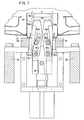
- FIG. 1 is a schematic view of a welding system according to an embodiment of the present invention;
- FIG. 2 is a perspective view of a welding jig according to the embodiment of the present invention together with a motorcycle fuel tank;
- FIG. 3 is a front elevational view, partly in cross section, of the welding jig according to the embodiment of the present invention together with the motorcycle fuel tank;
- FIG. 4 is a side elevational view, partly omitted from illustration, of the welding jig according to the embodiment of the present invention together with the motorcycle fuel tank;
- FIG. 5 is a front elevational view of a cylinder, a clamp arm, attachments, and surrounding parts;
- FIG. 6 is a cross-sectional view of an attachment;
- FIG. 7 is a front elevational view of a positioning mechanism in a condition in which hooks thereof are elevated;
- FIG. 8 is a front elevational view of the positioning mechanism when the hooks thereof are lowered;
- FIG. 9 is a perspective view of an inner jig, an inner side panel, and an outer side panel:
- FIG. 10 is a block diagram of a controller;
- FIG. 11 is a flowchart of a welding process performed using the welding system according to the embodiment of the present invention;
- FIG. 12 is a schematic view showing a welding path;
- FIG. 13 is a schematic view showing the manner in which the outer side panel is welded while it is being pressed by an attachment;
- FIG. 14 is a schematic view showing a welding line, an abutment point, a reference point, and a welding point; and
- FIG. 15 is a perspective view of a fuel tank having flanges.
-
- An embodiment of the present invention will be described below with reference to FIGS. 1 through 14. A welding method, a
welding system 10, and awelding jig 10a according to the embodiment serve to weld afuel tank 12 for a motorcycle. - As shown in FIG. 1, the
welding system 10 has awelding jig 10a (see FIG. 2) for holding thefuel tank 12, ajig robot 10b for setting thefuel tank 12 held by thewelding jig 10a at a predetermined position, a welding robot (welding machine) 10c for performing a welding process, and acontroller 10d. Thecontroller 10d is connected to cylinders 28 (see FIG. 2) of thewelding jig 10a, a positioning mechanism 44 (see FIG. 7), thejig robot 10b, and thewelding robot 10c, for controlling thewelding system 10 in its entirety. - As shown in FIG. 2, the
welding jig 10a is a jig for fixing anouter side panel 14 and aninner side panel 16 of themotorcycle fuel tank 12 when theouter side panel 14 and theinner side panel 16 are welded to each other. Thewelding jig 10a has anouter jig 18 for supporting theouter side panel 14 and aninner jig 20 for supporting theinner side panel 16. As shown in FIG. 2, thefuel tank 12 has its right side positioned forwardly (closer to the steering handle of the motorcycle) and its left side positioned rearwardly (closer to the seat of the motorcycle). - The
outer jig 18 is mounted on the tip end of thejig robot 10b (see FIG. 1) and is set at a predetermined position for the welding process. The welding process is performed by thewelding robot 10c. Thejig robot 10b, thewelding robot 10c, thecylinder 28, and so forth, are controlled by thecontroller 10d. - The
outer side panel 14 of thefuel tank 12 has a lower portion in FIG. 2 supported by a plurality oflower supports 22 and side and end portions supported by a plurality ofattachments 24. Each group of two or three of theattachments 24 is mounted on a single clamp arm (arm) 26. There are a total of eightclamp arms 26, four in each of left and right symmetrical arrays, which are individually openable and closable bycylinders 28. - As shown in FIGS. 3 and 4, the
outer side panel 14 has ends 15 extended inwardly, and theinner side panel 16 has ends whose inner surfaces are superposed on the outer surfaces of the ends of theouter side panel 14. A contact region 120 (see FIG. 13) where the ends of theouter side panel 14 and theinner side panel 16 are superposed is welded by thewelding robot 10c, thereby performing one-side welding of a fillet joint. The fuel tank has afuel inlet 36 disposed in a lower portion of theouter side panel 14. - The
outer jig 18 has twovertical frames 38 extending rearwardly from a position substantially beneath thefuel inlet 36, at a substantially constant spaced interval from the lower surface of theouter side panel 14, and fourauxiliary frames 40 extending laterally, obliquely forwardly, and obliquely rearwardly, on each of left and right sides thereof. A plurality oflower supports 22 for supporting theouter side panel 14 from below are mounted on the upper surfaces of the auxiliary frames 40. Rearend support members 42 for supporting lateral sides of the rear end of theouter side panel 14 are mounted on the rear ends of the vertical frames 38. The lower supports 22 and the rearend support members 42 may be made of a synthetic resin, such as nylon or the like. - A
positioning mechanism 44, which is inserted into thefuel inlet 36 for supporting thefuel tank 12 from inside thereof, is mounted on the front ends of the twovertical frames 38. - As shown in FIG. 5, a
base plate 46 and one of thecylinders 28 for opening and closing theclamp arms 26 are mounted on the distal end of each of the auxiliary frames 40. Thebase plate 46 and thecylinder 28 make up an opening/closing mechanism 47. Thecylinder 28 has acylinder tube 28a supported by a shaft on thebase plate 46 for swinging movement. Thecylinder 28 extends and contracts arod 28b to open and close theclamp arm 26. - The
clamp arm 26 has a lower portion supported for swinging movement on anupper shaft 46a on thebase plate 46. Theclamp arm 26 has aprotrusion 26a projecting slightly outwardly from the lower portion thereof and supported by a shaft on the distal end of therod 28b of thecylinder 28. Theclamp arm 26 also has astopper 26b projecting slightly inwardly from the lower portion thereof. When theclamp arm 26 is closed, thestopper 26b abuts against an upper surface of thebase plate 46, thereby positioning theclamp arm 26. - The
clamp arm 26, when it is closed by the opening/closing mechanism 47, has afirst arm member 26c extending upwardly from theshaft 46a, asecond arm member 26d mounted on the distal end of thefirst arm member 26c and inclined slightly inwardly, and athird arm member 26e mounted on the distal end of thesecond arm member 26d and inclined more inwardly than thesecond arm member 26d. With this structure, when theclamp arm 26 is closed, theclamp arm 26 is spaced at a substantially constant interval from theouter side panel 14. Thethird arm member 26e may be dispensed with, depending on the location (see FIG. 4). - The
first arm member 26c, thesecond arm member 26d, and thethird arm member 26e haverespective holes 48 defined therein for installingrespective attachments 24. Two or threeattachments 24 are mounted on eachclamp arm 26. - As shown in FIG. 6, each of the
attachments 24 comprises asleeve 50 mounted in ahole 48 in theclamp arm 26, anattachment shaft 54 movable in and along acentral bore 52 of thesleeve 50, aspring bearing plate 56 mounted on the distal end of theattachment shaft 54, an adjustment nut 60 (pressing force adjuster) threaded overscrew threads 58 which are formed on the outer circumferential surface of the distal end of thesleeve 50, awasher 62 held against theadjustment nut 60, and a spring (resilient body) 64 disposed between thespring bearing plate 56 and thewasher 62. - A
ball 66, and an abutment (tilting mechanism) 68, which is tiltable in any direction while being held in sliding contact with theball 66, are mounted on the distal end of thespring bearing plate 56. Theabutment 68 comprises twocomponents ball 66 therebetween. - A fixing
nut 72 is threaded overscrew threads 70 that are formed on the outer circumferential surface of the rear end of thesleeve 50. Theclamp arm 26 is clamped in position between anannular flange 74, which is mounted substantially centrally on thesleeve 50 and the fixingnut 72. One or moreannular shims 76, for adjusting the length by which theattachment 24 projects with respect to theclamp arm 26 when necessary, are inserted between theannular flange 74 and theclamp arm 26. - A
cylindrical bushing 78 having a lubricating function is inserted in the bore of thesleeve 50. Theattachment shaft 54 is smoothly movable with respect to thebushing 78. - The
attachment shaft 54 has a smaller diameter externally threadedportion 80 formed on the rear portion thereof, wherein a knob 82 (pressing force adjuster) and an end stopper 84 (pressing force adjuster) are threaded over the externally threadedportion 80. When theknob 82 and theend stopper 84 are turned, the compression of thespring 64 and the projection of theattachment shaft 54 can be adjusted. After such an adjustment, theknob 82 and theend stopper 84 are fixed in position as double nuts that are tightened against each other. - When the
adjustment nut 60 is turned, the compression of thespring 64 can be adjusted. Specifically, the degree of compression of thespring 64 is adjustable by means of theknob 82, theend stopper 84, and theadjustment nut 60. Actually,knob 82 and theend stopper 84 are turned to roughly adjust the compression of thespring 64, and theadjustment nut 60 is turned to finely adjust the compression of thespring 64. - When the distal end of the
abutment 68 is pushed by theouter side panel 14, theattachment shaft 54 is moved toward the rear end thereof. At this time, theattachment shaft 54 compresses thespring 64, and moves a certain distance depending on the repulsive force of thespring 64. - As shown in FIG. 7k, the
positioning mechanism 44 is disposed beneath thefuel inlet 36, at an intermediate location between the twovertical frames 38. Thepositioning mechanism 44 has an upper portion inserted in thefuel inlet 36. Thepositioning mechanism 44 has aninsert member 88 fixed to aframe body 86, amovable member 92 vertically movable by arod 90, and twohooks 94 supported by shafts on themovable member 92 for being tiltable slightly outwardly when themovable member 92 is lowered. Theinsert member 88 has a horizontal width D, which is slightly smaller than the inside diameter of thefuel inlet 36. - The two hooks 94 comprise upwardly extending plates shaped bilaterally symmetrically. Each of the
hooks 94 has anupper tooth 94a projecting slightly outwardly, a longitudinallyoblong hole 94b, and alower swing hole 94c. Theoblong hole 94b has a lower portion bent slightly outwardly. - Two bilaterally symmetrical fixed
support shafts 88a project from theinsert member 8 at a substantially central height thereof. Two bilaterally symmetricalmovable support shafts 92a project from an upper portion of themovable member 92. As shown in FIG. 7. the fixedsupport shafts 88a and themovable support shafts 92a project toward the direction of the viewer. The fixedsupport shafts 88a are inserted in theoblong holes 94b defined in thehooks 94, and themovable support shafts 92a are fitted in the swing holes 94c defined in thehooks 94. - For placing the
outer side panel 14 on theouter jig 18, therod 90 is moved upwardly by a cylinder (not shown). At this time, the twohooks 94 are tilted inwardly and positioned within the horizontal width D of theinsert member 88. When theouter side panel 14 is placed on theouter jig 18, an upper portion of theinsert member 88 and upper portions of thehooks 94 are inserted into thefuel inlet 36. - As shown in FIG. 8, when the
rod 90 is lowered, themovable member 92 and thehooks 94 are also lowered. Thehooks 94 are guided by the fixedsupport shafts 88a that are inserted in theoblong holes 94b, and are tilted outwardly. Theteeth 94a of thehooks 94 project beyond the inside diameter of thefuel inlet 36. Upon further descent of thehooks 94, theteeth 94a of thehooks 94 abut against an end of thefuel inlet 36, thus holding theouter side panel 14. - As shown in FIG. 9, the
inner jig 20 has an elongateupper plate 100, anextension rod 102 projecting from a rear end of theupper plate 100,grips 104 mounted on an upper surface of theupper plate 100, and a plurality ofnylon presser plates 106 fixed to a lower surface of theupper plate 100 and matching the shape of theinner side panel 16.Joint levers 108 are mounted respectively on a rear end of theextension rod 102 and on the foremost one 106a of thepresser plates 106. Each of thepresser plates 106 is of a bilaterally symmetrical shape, projecting from theupper plate 100 at its center, and has lateral end surfaces or a lower surface matching the shape of theinner side panel 16. Thejoint levers 108 respectively engage with joint hooks 110 (see FIG. 2), which are mounted on front and rear ends of theouter jig 18. - As shown in FIG. 10, the
controller 10d has a weldingrobot control unit 130 for controlling thewelding robot 10c, a jigrobot control unit 132 for controlling thejig robot 10b, apositioning control unit 134 for vertically moving therod 90 of thepositioning mechanism 44, and first through eighthcylinder control units cylinders 28, respectively. The weldingrobot control unit 130 and the jigrobot control unit 132 control respective motor drivers, not shown, which operate thewelding robot 10c and thejig robot 10b. The weldingrobot control unit 130 and the jigrobot control unit 132 can detect attitudes of thewelding robot 10c and thejig robot 10b, as well as the positions and speeds of various parts thereof, through feedback signals. Pneumatic valves, not shown, are disposed between thepositioning control unit 134 and thepositioning mechanism 44, and also between the first through eighthcylinder control units 136 through 150 and thecylinders 28, wherein such valves function to operate therod 90 and thecylinders 28. - The
controller 10d also has awelding control unit 152 as a main control unit, including a weldingpoint determining unit 154 for transferring data to and from the weldingrobot control unit 130 and the jigrobot control unit 132. The weldingpoint determining unit 154 gives control instructions to the first through eighthcylinder control units 136 through 150. - A process of welding the
outer side panel 14 and theinner side panel 16 of thefuel tank 12 using thewelding system 10 and thewelding jig 10a will be described below with reference to FIGS. 11 through 14. The procedure to be described below basically is performed by thecontroller 10d, with certain setting operations being carried out by the operator. - Two welding cycles are performed on left and right sides, as indicated by points Q1 through Q6, and Q7 through Q12, which as shown in FIG. 12, represent a welding sequence. The points Q1 through Q12 are points on welding lines V. Point Q1 is a starting point, point Q6 a pausing point, point Q7 a resuming point, and point Q12 an ending point. Points Q2 through Q6 and points Q8 through Q11 are reference points on the welding lines V, which are closest to abutment points P (see FIGS. 13 and 14) where the
attachments 24 on theclamp arms 26 disposed closely to these points and thefuel tank 12 abut against each other. - The welding process is started from the foremost point Q1 on the central line of the
fuel tank 12, and is performed progressively through points Q2 to Q6. Point Q6 is the rearmost point on the central line of thefuel tank 12. After the welding process has been performed up to point Q6, the welding process is interrupted and then goes to point Q7. Point Q7 is a point near point Q1 and is set at a location where lap welding can be performed. The welding process is started again from point Q7, and is performed progressively through points Q7 to Q12. Point Q12 is a point near point Q7 and is set at a location where lap welding can be performed. The welding process is carried out along the above path by thewelding robot 10c (see FIG. 1), and may be performed in cooperation with thejig robot 10b (see FIG. 1). - Specifically, in step S1 shown in FIG. 11, the
clamp arms 26 of theouter jig 18 are opened (see FIG. 5), and the rod 90 (see FIG. 7) and thehooks 94 are lifted. Then, the operator places theouter side panel 14 of thefuel tank 12 on thelower supports 22 with thefuel inlet 36 oriented downwardly. At this time, theouter side panel 14 is placed on thelower supports 22, while theinsert member 88 of thepositioning mechanism 44 is inserted into thefuel inlet 36. Since thehooks 94, as they are lifted, are set to a width smaller than the inside diameter of thefuel inlet 36, thehooks 94 are kept out of interference with thefuel inlet 36. Inasmuch as the horizontal width D of theinsert member 88 is slightly smaller than the inside diameter of thefuel inlet 36, the upper portion of theinsert member 88 can be inserted into thefuel inlet 36, thereby simply and accurately positioning theouter side panel 14 with respect to theouter jig 18. - In step S2, the
rod 90 of thepositioning mechanism 44 is lowered, thereby lowering themovable member 92 and the two hooks 94 (see FIG. 8). As the twohooks 94 are lowered, they are tilted outwardly until theteeth 94a abut against the end of thefuel inlet 36. Theouter side panel 14 is now firmly secured with respect to theouter jig 18. - In step S3, the
inner side panel 16 of thefuel tank 12 is placed on an upper portion of theouter side panel 14.
At this time, theinner side panel 16 is placed on the upper portion of theouter side panel 14, such that the inwardly extended ends 15 of theouter side panel 14 and the peripheral ends of theinner side panel 16 are substantially superposed on each other. Thereafter, theinner jig 20 is placed on an upper portion of theinner side panel 16. - In step S4, the eight
cylinders 28 are actuated to close theclamp arms 26, until thestoppers 26b are brought into abutment against the upper surfaces of thebase plates 46. When theclamp arms 26 are closed, theabutments 68, which serve as distal ends of therespective attachments 24, abut against theouter side panel 14. At this time, theabutments 68 abut against theouter side panel 14 while compressing thesprings 64, and theouter side panel 14 is pressed under a pressing force depending on the degree of compression of thesprings 64. The pressing force can be adjusted when theadjustment nuts 60 or theknobs 82 are turned, and therefore may be adjusted to an appropriate level in advance by an operator. - When the
abutments 68 of theattachments 24 hold theouter side panel 14, theouter side panel 14 is set in position, and hence a flexed state that would otherwise occur due to gravity can be corrected. Since the eightclamp arms 26 are disposed four each, in left and right symmetrical arrays, they hold thefuel tank 12 in a well balanced state. - Because the
abutments 68 have a structure that permits tilting about theballs 66, the distal end faces of theabutments 68 are not held in localized abutment, but rather are reliably held in full abutment against theouter side panel 14. - In step S5, the operator brings the
joint levers 108 on the opposite ends of theinner jig 20 into engagement with the joint hooks 110. Since thepresser plates 106 have shapes that match theinner side panel 16, theinner side panel 16 is accurately positioned and fixed with respect to theouter side panel 14. - In step S6, the
welding robot 10c commences a welding operation, for welding theouter side panel 14 and theinner side panel 16 to each other (see FIG. 1). The welding process is continuously performed along the welding line V (see FIG. 14), and may be one of various welding processes including TIG (inert-gas tungsten-arc welding), MIG (inert-gas metal-arc welding), laser beam welding, etc. - In step S7, the welding process is performed along the welding line V. For example, when the welding process is performed from point Q1 toward point Q2, as shown in FIGS. 13 and 14, an electrode 122 (or an arc or the like) is moved along the
contact region 120 where the end of theinner side panel 16 contacts theouter side panel 14.Weld beads 124 are formed along thecontact region 120, thereby welding theinner side panel 16 and theouter side panel 14 to each other. - As the
inner side panel 16 and theouter side panel 14 are welded to each other, a welded region M is melted at a high temperature and hence becomes deformed. If the workpiece is overly restrained during welding, then when the melted region is cooled and solidified, such deformation is not relieved, but rather causes theweld beads 124 to become strained (i.e., thermally strained) therein, and such thermally strainedweld beads 124 may possibly become cracked. - According to the welding process performed using the
welding jig 10a, when theweld beads 124 are formed due to heat and the welded region is expanded, theouter side panel 14 is deformed and pushed outwardly, as indicated by the arrow A0. At this time, the abutment point P, which is held in attachment against theabutment 68 of theattachment 24, undergoes a force A1 depending on the arrow A0. More specifically, the force A1 is determined depending on the direction and size of the arrow A0, as well as the position of the abutment point P, and is oriented substantially outwardly. - The abutment point P causes the
abutment 68 to compress thespring 64 under the force A1. When the force A1 is small, the compression of thespring 64 is small, and when the force A1 is large, the compression of thespring 64 is large. - The initial abutment point P can be displaced to a position Px, where the repulsive force of the
compressed spring 64 and the force A1 are held in equilibrium. Therefore, theattachment 24 functions to allow the weldedbeads 124 to shrink, while absorbing the thermal strain at a high temperature, after theinner side panel 16 and theouter side panel 14 have been welded to each other. Thus, any thermal strain exerted within the weldedbeads 124 after they are cooled is very small. - Inasmuch as the distance between the abutment point P and the position Px is very small, such a distance will not appear as a dimensional error.
- In FIG. 13, arrow A0 represents the direction in which the welded region is expended due to the formation of
weld beads 124, wherein the arrow is illustrated as being substantially aligned with the surface of the end of theouter side panel 14. However, thermal strain may be absorbed without regard to the direction in which the arrow A0 is oriented. For example, if the arrow A0 is directed outwardly, then thespring 64 of theattachment 24 will be compressed, depending on the direction and size thereof, in order to absorb the thermal strain. - If the arrow A0 is directed inwardly, then
weld beads 124 are formed while shrinking, and theattachment 24 does not restrain the shrinking deformation of theweld beads 124. - In step S7, the welding
point determining unit 154 determines a welded spot M (see FIG. 14), where the welding process takes place, from data supplied from the weldingrobot control unit 130 and the jigrobot control unit 132. - In step S8, the welding
point determining unit 154 calculates a distance L1 between the position of the welded spot M and a reference point (e.g., point Q2), and compares the distance L1 with a preset distance L0. If the distance L0 is smaller than the distance L1, then control returns to step S7 to continue the welding process. If the distance L0 is greater than the distance L1, e.g., if the welded spot M in FIG. 14 goes beyond a point B which is spaced from point Q2 by the distance L0, then control goes to step S9. - In step S9, the welding
point determining unit 154 instructs thecylinder 28 of a corresponding opening/closing mechanism 47 to open theclamp arm 26, spacing theattachment 24 away from thefuel tank 12. For example, when the welding process is performed toward point Q2 shown in FIG. 12, the weldingpoint determining unit 154 instructs the first cylinder control unit 136 (see FIG. 10), which controls thecylinder 28 corresponding to point Q2, to open only theattachment 24 corresponding to point Q2. - While the
outer side panel 14 is held by theattachments 24, thermal strain can be absorbed by thesprings 64. However, repulsive forces of thesprings 64 do exert certain restraint forces, which tend to develop a weak thermal strain depending thereon. By contrast, in step S9, since theattachment 24 is spaced from theouter side panel 14, no restraint forces are applied to theouter side panel 14, further preventing thermal strain from being produced. - If the
attachment 24 is spaced from theouter side panel 14 too early, then it fails to perform its function to hold theouter side panel 14. Consequently, the distance L0 needs to be set to a suitable value. Actually, the distance L0 should preferably be set to a value that is equal to or smaller than 20 mm. If the distance L0 is set to 20 mm, then when the welded spot M reaches a point that is spaced from point Q2 by the distance L0 of 20 mm and theattachment 24 is spaced from theouter side panel 14, a location which is spaced about 25 mm from point Q2 has already been welded and substantially solidified. Therefore, even when theattachment 24 is spaced from theouter side panel 14, theouter side panel 14 is not unduly displaced out of position. Since theattachment 24 is spaced from theouter side panel 14 only at the location where the welding process has essentially been completed, thefuel tank 12 is not held laterally out of balance. - In step S10, it is determined whether the welded point M has reached point Q6 or not. If the welded point M has reached point Q6, then the welding process is interrupted and goes to point Q7 in step S11. Then, control goes back to step S6, and the welding process is resumed from point Q7 toward point Q12.
- In step S12, it is determined whether the welded point M has reached point Q12 or not. If the welded point M has not reached point Q12, then control goes back to step S7.
If the welded point M has reached point Q12, then control goes to step S13. - In step S13, the welding process is ended. After the welding process is ended, the operator releases the
joint levers 108, and removes theinner jig 20. Therods 28b of thecylinders 28 are contracted, opening theclamp arms 26. Therod 90 of thepositioning mechanism 44 is lifted, and the weldedfuel tank 12 is removed in step S14. - In steps S7 and S8, the positional relationship between the welded spot M and the reference point (e.g., point Q2) is determined in real time. However, the reference point may be related to an attitude of the
welding robot 10c in advance, and when thewelding robot 10c assumes a predetermined attitude, theattachment 24 may be spaced from theouter side panel 14. Alternatively, the welding process may be timed from its start, and theattachments 24 may progressively be operated after predetermined periods of time. - According to the present embodiment, as described above, at high temperatures during and after the welding process, deformation of the welded
beads 124 due to thermal strain is absorbed by thesprings 64 of theattachments 24. Therefore, essentially no thermal strain is present in theweld beads 124 after they are cooled. Consequently, theweld beads 124 are prevented from cracking, resulting in an increased yield. - Since the
attachments 24 can be opened and closed by theclamp arms 26, thefuel tank 12 as a workpiece can easily be attached and detached. Further, the position of theclamp arms 26 can accurately be determined by thestoppers 26b. - The force with which the abutments, as distal ends of the
attachments 24, press theouter side panel 14 can be adjusted by theadjustment nuts 60 and theknobs 82. - Since the
outer jig 18 comprises apositioning mechanism 44 that is inserted and fixed in thefuel inlet 36 of thefuel tank 12, thefuel tank 12 can quickly and accurately be positioned with respect to theouter jig 18. Theinner jig 20 also is able to position theinner side panel 16 of thefuel tank 12 accurately with respect to theouter side panel 14. - According to the present embodiment, furthermore, when the welded spot M moves along the welding line V, the
attachments 24 are progressively spaced from thefuel tank 12 in the order in which they are approached by the welded spot M. Therefore, restraint forces on theouter side panel 14 of thefuel tank 12 are eliminated, reducing effects of thermal strain caused by welding, and preventing thefuel tank 12 from cracking. As a result,fuel tanks 12 can be manufactured with an increased yield. - Since the
attachments 24 hold thefuel tank 12 withsprings 64, the effects of thermal strain caused by welding can be reduced even while theattachments 24 are holding thefuel tank 12. - Because the outer surface of the end of the
outer side panel 14 and the inner surface of the end of theinner side panel 16 are superposed and held by theattachments 24 while they are being welded, the weldedfuel tank 12 is free of flanges. Therefore, thefuel tank 12 can appropriately be used as the fuel tank for an American-type motorcycle that needs to be aesthetically pleasing. - The
welding jig 10a described above comprises eightclamp arms 26. However, the number ofclamp arms 26 may be increased or reduced depending on the size and shape of thefuel tank 12. For example, a fuel tank may have a total of fourclamp arms 26, two each, provided in left and right symmetrical arrays. The number ofattachments 24 mounted on asingle clamp arm 26 may also be increased or reduced depending on the size and shape of thefuel tank 12. - The welding method, the welding system, and the welding jig according to the present invention are not limited to the above embodiment, but may have various arrangements and steps without departing from the scope of the invention.
Claims (12)
- A welding method for welding a motorcycle fuel tank (12), using a plurality of opening/closing mechanisms (47) having one or more attachments (24), for bringing the attachments (24) into and out of abutting engagement with the fuel tank (12), comprising the steps of:bringing the attachments (24) into abutting engagement with the fuel tank (12) by operating said opening/closing mechanisms (47), thereby holding said fuel tank (12); andbringing the attachments (24) out of abutting engagement with the fuel tank (12) by operating said opening/closing mechanisms (47), in an order in which the attachments (24) are approached by a welded spot (M) where the fuel tank (12) is welded, as said welded spot (M) moves along a welding line (V).
- A welding method according to claim 1, wherein said attachments (24) hold said fuel tank (12) through resilient bodies (64).
- A welding method according to claim 1, wherein said fuel tank (12) comprises:wherein said attachments (24) hold the fuel tank (12) while outer surfaces of the ends of said outer side panel (14) and inner surfaces of ends of said inner side panel (16) are superposed, or while the ends of said outer side panel (14) and the ends of said inner side panel (16) are in abutment against each other.an outer side panel (14) having inwardly extended ends; andan inner side panel (16) welded to said outer side panel (14),
- A welding method according to claim 1, wherein said attachments (24) are brought out of abutting engagement with said fuel tank (12) by said opening/closing mechanisms (47), when said welded spot (M) reaches a point spaced 20 mm or less from a reference point (Q2) on said welding line (V), which is closest to an abutment point (P) where each of said attachments (24) and said fuel tank (12) abut against each other.
- A welding system (10) for welding a motorcycle fuel tank (12), which has an outer side panel (14) having inwardly extended ends and an inner side panel (16) welded to said outer side panel (14), comprising:wherein said controller (10d) controls said opening/closing mechanisms (47) to bring said attachments (24) into abutting engagement with said fuel tank (12) to hold said fuel tank (12), and thereafter, said controller (10d) determines a position of a welded spot (M) where said fuel tank (12) is welded by said welding machine (10c), and the positions of said attachments (24), and if a relative position of said welded spot (M) with respect to each of said attachments (24) satisfies a predetermined standard, then said controller (10d) controls at least one of said opening/closing mechanisms (47) to bring said attachments (24) out of abutting engagement with said fuel tank (12).a plurality of opening/closing mechanisms (47) having one or more attachments (24), for bringing said attachments (24) into and out of abutting engagement with said fuel tank (12);a welding machine (10c) automatically operable for welding said fuel tank (12); anda controller (10d) connected to said opening/closing mechanisms (47) and said welding machine (10c),
- A welding jig (10a) for holding a motorcycle fuel tank (12) when the fuel tank (12) is welded, comprising:a plurality of attachments (24) for holding said fuel tank (12) through resilient bodies (64).
- A welding jig according to claim 6, wherein said attachments (24) are mounted on respective arms (26), each of said arms (26) having respective opening/closing mechanisms (47); and
when said arms (26) are fully opened, said arms (26) are opened wide enough to allow said fuel tank (12) to be attached and detached, and when said arms (26) are fully closed, said arms (26) are positioned by respective stoppers (26b) to hold said fuel tank (12) with said attachments (24). - A welding jig according to claim 6, wherein said attachments (24) comprise pressing force adjusters (60) for adjusting a pressing force with which said fuel tank (12) is held.
- A welding jig according to claim 6, further comprising:wherein said attachments (24) are provided in said outer jig (18), and hold side portions and/or end portions of said outer side panel (14).an outer jig (18) for supporting an outer side panel (14) of said fuel tank (12); andan inner jig (20) for supporting an inner side panel (16) of said fuel tank (12),
- A welding jig according to claim 9, wherein said outer side panel (14) of said fuel tank (12) comprises inwardly extended ends,
wherein said attachments (24) hold said fuel tank (12) while outer surfaces of the ends of said outer side panel (14) and inner surfaces of ends of said inner side panel (16) are superposed, or while the ends of said outer side panel (14) and the ends of said inner side panel (16) are in abutment against each other. - A welding jig according to claim 6, further comprising:a positioning mechanism (44) for insertion into a fuel inlet (36) defined in an upper surface of said fuel tank (12), and contacting an inner portion of said fuel tank (12) to hold said fuel tank (12).
- A welding jig according to claim 6, wherein each of said attachments (24) has a distal end abutting against said fuel tank (12), said distal end having a tilting mechanism (68) tiltable in any direction.
Applications Claiming Priority (5)
| Application Number | Priority Date | Filing Date | Title |
|---|---|---|---|
| JP2002241528 | 2002-08-22 | ||
| JP2002241528A JP3895236B2 (en) | 2002-08-22 | 2002-08-22 | Welding jig |
| JP2002241535A JP3907552B2 (en) | 2002-08-22 | 2002-08-22 | Welding method and welding system |
| JP2002241535 | 2002-08-22 | ||
| PCT/JP2003/010297 WO2004018135A1 (en) | 2002-08-22 | 2003-08-13 | Welding method, welding system, and welding jig |
Publications (3)
| Publication Number | Publication Date |
|---|---|
| EP1552900A1 true EP1552900A1 (en) | 2005-07-13 |
| EP1552900A4 EP1552900A4 (en) | 2008-08-27 |
| EP1552900B1 EP1552900B1 (en) | 2011-10-05 |
Family
ID=31949559
Family Applications (1)
| Application Number | Title | Priority Date | Filing Date |
|---|---|---|---|
| EP03792679A Expired - Fee Related EP1552900B1 (en) | 2002-08-22 | 2003-08-13 | Method and system of welding a fuel tank for a motorcycle |
Country Status (4)
| Country | Link |
|---|---|
| US (2) | US7544912B2 (en) |
| EP (1) | EP1552900B1 (en) |
| AU (1) | AU2003255026A1 (en) |
| WO (1) | WO2004018135A1 (en) |
Cited By (10)
| Publication number | Priority date | Publication date | Assignee | Title |
|---|---|---|---|---|
| WO2008068397A1 (en) * | 2006-12-06 | 2008-06-12 | Aircelle | Brazing method and corresponding device |
| CN102229031A (en) * | 2010-09-21 | 2011-11-02 | 上海交运汽车精密冲压件有限公司 | Pneumatic welding clamp |
| CN103223564A (en) * | 2013-05-06 | 2013-07-31 | 力帆实业(集团)股份有限公司 | Welding tool for motorcycle frame midbody assembly |
| CN103551776A (en) * | 2013-10-17 | 2014-02-05 | 力帆实业(集团)股份有限公司 | Welding fixture for motorcycle fuel tank left and right guard supports |
| CN103817477A (en) * | 2014-03-04 | 2014-05-28 | 铜陵市精方圆机械有限公司 | Assembly and welding tooling table for harvesting machine grain box bottom plate |
| CN104227306A (en) * | 2014-09-29 | 2014-12-24 | 河北昊昱焊接技术研究所有限公司 | Positioning tool for welding transformer tank |
| CN105479091A (en) * | 2016-01-22 | 2016-04-13 | 安徽江淮汽车股份有限公司 | Flexible positioning mechanism |
| CN105562994A (en) * | 2016-02-18 | 2016-05-11 | 力帆实业(集团)股份有限公司 | Built-in fuel tank welding tool of motorcycle |
| CN105598622A (en) * | 2016-02-18 | 2016-05-25 | 力帆实业(集团)股份有限公司 | Motorcycle integrated fuel tank assembling method |
| CN105666013A (en) * | 2016-04-12 | 2016-06-15 | 中车长春轨道客车股份有限公司 | Automatic support plate installing and welding tool suitable for various urban rail car models |
Families Citing this family (10)
| Publication number | Priority date | Publication date | Assignee | Title |
|---|---|---|---|---|
| GB201009219D0 (en) * | 2010-06-02 | 2010-07-21 | Airbus Operations Ltd | Aircraft component manufacturing method and apparatus |
| US9409249B1 (en) | 2012-01-19 | 2016-08-09 | Christopher Bryan Trussell | Welding assistance systems |
| TWI508811B (en) * | 2012-08-08 | 2015-11-21 | Kwang Yang Motor Co | Locomotive tank welding method |
| US8950649B2 (en) * | 2013-03-14 | 2015-02-10 | Us Synthetic Corporation | Apparatus for brazing radial bearings and related methods |
| US9802277B2 (en) * | 2014-07-18 | 2017-10-31 | Lincoln Global, Inc. | Tank welding fixture |
| CN107283109A (en) * | 2017-07-22 | 2017-10-24 | 合肥亚美科技股份有限公司 | A kind of scissor aerial work platform fork-shearing frame welds die craft equipment |
| CN108237369B (en) * | 2017-12-30 | 2020-02-14 | 安徽大昌科技股份有限公司 | Left positioning and clamping tool for front assembly of left and right side wall inner plates of automobile |
| US11130212B2 (en) * | 2019-02-07 | 2021-09-28 | Raytheon Technologies Corporation | Infinitely directional translating clamp for welding a fan blade cover |
| US11767087B2 (en) * | 2021-06-30 | 2023-09-26 | FabX Industries, Inc. | Automated method for nose cone manufacturing |
| TWI804970B (en) * | 2021-09-03 | 2023-06-11 | 陳弘峻 | Welding jig for lifting components of a truck tail plate |
Citations (6)
| Publication number | Priority date | Publication date | Assignee | Title |
|---|---|---|---|---|
| US2867003A (en) * | 1956-02-13 | 1959-01-06 | Sierracin Corp | Apparatus for casting plastic sheets |
| JPS59110182U (en) * | 1983-01-13 | 1984-07-25 | 本田技研工業株式会社 | Welding equipment for fuel tanks, etc. |
| US4491306A (en) * | 1981-07-07 | 1985-01-01 | Vereinigte Flugtechnische Werke Gmbh | Holding curved workpieces |
| US4652719A (en) * | 1985-05-29 | 1987-03-24 | Honda Giken Kogyo Kabushiki Kaisha | Workpiece feeding apparatus in seam welding machine |
| US4921293A (en) * | 1982-04-02 | 1990-05-01 | The United States Of America As Represented By The Administrator Of The National Aeronautics And Space Administration | Multi-fingered robotic hand |
| JPH09314351A (en) * | 1996-05-28 | 1997-12-09 | Daihatsu Motor Co Ltd | Seam weld line automatic copying device |
Family Cites Families (8)
| Publication number | Priority date | Publication date | Assignee | Title |
|---|---|---|---|---|
| DE3245178C2 (en) | 1982-12-07 | 1986-12-11 | Philips Patentverwaltung Gmbh, 2000 Hamburg | Symmetrical temperature sensor |
| JPS59230877A (en) * | 1983-05-26 | 1984-12-25 | スズキ株式会社 | Manufacture of fuel tank for motorcycle |
| JPS61162389A (en) | 1985-01-11 | 1986-07-23 | Konishiroku Photo Ind Co Ltd | Thermal transfer recording medium |
| JPS61162389U (en) * | 1985-03-28 | 1986-10-08 | ||
| JPH1076985A (en) | 1996-09-05 | 1998-03-24 | Yamaha Motor Co Ltd | Fuel tank for motorcycle |
| JP3542261B2 (en) | 1997-12-24 | 2004-07-14 | 本田技研工業株式会社 | Seam welding machine |
| JPH11321752A (en) | 1998-05-07 | 1999-11-24 | Honda Motor Co Ltd | Fuel tank for motorcycle |
| JP2003048097A (en) | 2001-08-01 | 2003-02-18 | Honda Motor Co Ltd | Method and tool for correcting welding space |
-
2003
- 2003-08-13 AU AU2003255026A patent/AU2003255026A1/en not_active Abandoned
- 2003-08-13 WO PCT/JP2003/010297 patent/WO2004018135A1/en active Application Filing
- 2003-08-13 US US10/525,124 patent/US7544912B2/en not_active Expired - Fee Related
- 2003-08-13 EP EP03792679A patent/EP1552900B1/en not_active Expired - Fee Related
-
2009
- 2009-04-22 US US12/386,702 patent/US20090206146A1/en not_active Abandoned
Patent Citations (6)
| Publication number | Priority date | Publication date | Assignee | Title |
|---|---|---|---|---|
| US2867003A (en) * | 1956-02-13 | 1959-01-06 | Sierracin Corp | Apparatus for casting plastic sheets |
| US4491306A (en) * | 1981-07-07 | 1985-01-01 | Vereinigte Flugtechnische Werke Gmbh | Holding curved workpieces |
| US4921293A (en) * | 1982-04-02 | 1990-05-01 | The United States Of America As Represented By The Administrator Of The National Aeronautics And Space Administration | Multi-fingered robotic hand |
| JPS59110182U (en) * | 1983-01-13 | 1984-07-25 | 本田技研工業株式会社 | Welding equipment for fuel tanks, etc. |
| US4652719A (en) * | 1985-05-29 | 1987-03-24 | Honda Giken Kogyo Kabushiki Kaisha | Workpiece feeding apparatus in seam welding machine |
| JPH09314351A (en) * | 1996-05-28 | 1997-12-09 | Daihatsu Motor Co Ltd | Seam weld line automatic copying device |
Non-Patent Citations (2)
| Title |
|---|
| DATABASE WPI Week 198506 Thomson Scientific, London, GB; AN 1985-035814 XP002488591 -& JP 59 230877 A (SUZUKI MOTOR CO LTD) 25 December 1984 (1984-12-25) * |
| See also references of WO2004018135A1 * |
Cited By (19)
| Publication number | Priority date | Publication date | Assignee | Title |
|---|---|---|---|---|
| FR2909576A1 (en) * | 2006-12-06 | 2008-06-13 | Aircelle Sa | BRAZING METHOD AND CORRESPONDING DEVICE. |
| CN101528402B (en) * | 2006-12-06 | 2012-02-22 | 埃尔塞乐公司 | Brazing method and corresponding device |
| US8220698B2 (en) | 2006-12-06 | 2012-07-17 | Aircelle | Brazing method and corresponding device |
| WO2008068397A1 (en) * | 2006-12-06 | 2008-06-12 | Aircelle | Brazing method and corresponding device |
| CN102229031A (en) * | 2010-09-21 | 2011-11-02 | 上海交运汽车精密冲压件有限公司 | Pneumatic welding clamp |
| CN103223564A (en) * | 2013-05-06 | 2013-07-31 | 力帆实业(集团)股份有限公司 | Welding tool for motorcycle frame midbody assembly |
| CN103223564B (en) * | 2013-05-06 | 2015-04-01 | 力帆实业(集团)股份有限公司 | Welding tool for motorcycle frame midbody assembly |
| CN103551776A (en) * | 2013-10-17 | 2014-02-05 | 力帆实业(集团)股份有限公司 | Welding fixture for motorcycle fuel tank left and right guard supports |
| CN103551776B (en) * | 2013-10-17 | 2015-11-25 | 力帆实业(集团)股份有限公司 | The welding tooling of motorcycle tank left and right shield stand |
| CN103817477B (en) * | 2014-03-04 | 2016-08-17 | 铜陵市精方圆机械有限公司 | Grain box of harvester base plate assembly welding tooling platform |
| CN103817477A (en) * | 2014-03-04 | 2014-05-28 | 铜陵市精方圆机械有限公司 | Assembly and welding tooling table for harvesting machine grain box bottom plate |
| CN104227306A (en) * | 2014-09-29 | 2014-12-24 | 河北昊昱焊接技术研究所有限公司 | Positioning tool for welding transformer tank |
| CN105479091A (en) * | 2016-01-22 | 2016-04-13 | 安徽江淮汽车股份有限公司 | Flexible positioning mechanism |
| CN105479091B (en) * | 2016-01-22 | 2017-04-05 | 安徽江淮汽车集团股份有限公司 | A kind of flexible detent mechanism |
| CN105562994A (en) * | 2016-02-18 | 2016-05-11 | 力帆实业(集团)股份有限公司 | Built-in fuel tank welding tool of motorcycle |
| CN105598622A (en) * | 2016-02-18 | 2016-05-25 | 力帆实业(集团)股份有限公司 | Motorcycle integrated fuel tank assembling method |
| CN105598622B (en) * | 2016-02-18 | 2017-07-14 | 力帆实业(集团)股份有限公司 | A kind of motorcycle built-in oil-tank assembly method |
| CN105562994B (en) * | 2016-02-18 | 2017-07-14 | 力帆实业(集团)股份有限公司 | Motorcycle built-in oil-tank welding tooling |
| CN105666013A (en) * | 2016-04-12 | 2016-06-15 | 中车长春轨道客车股份有限公司 | Automatic support plate installing and welding tool suitable for various urban rail car models |
Also Published As
| Publication number | Publication date |
|---|---|
| EP1552900A4 (en) | 2008-08-27 |
| EP1552900B1 (en) | 2011-10-05 |
| US20090206146A1 (en) | 2009-08-20 |
| AU2003255026A1 (en) | 2004-03-11 |
| WO2004018135A1 (en) | 2004-03-04 |
| US20060151572A1 (en) | 2006-07-13 |
| US7544912B2 (en) | 2009-06-09 |
Similar Documents
| Publication | Publication Date | Title |
|---|---|---|
| US20090206146A1 (en) | Welding method, welding system, and welding jig for robotically welding a motorcycle fuel tank | |
| US4629109A (en) | Jig for welding frames | |
| JP4652363B2 (en) | Metal mounting device | |
| CN101115643A (en) | Seat frame system and method of manufacturing | |
| US5731566A (en) | Device for welding and/or cutting | |
| JP3847402B2 (en) | Resistance welding method | |
| JP3895236B2 (en) | Welding jig | |
| JP4699807B2 (en) | Welding equipment | |
| KR102196606B1 (en) | Welding Zig for Frame | |
| JP3272197B2 (en) | Lap welding jig | |
| JP3907552B2 (en) | Welding method and welding system | |
| JP4820116B2 (en) | Method for welding motorcycle frame | |
| JP2001340962A (en) | Method and apparatus for assembling auto-bicycle body frame | |
| JP3520698B2 (en) | Internal clamp device with gap filling means | |
| CN107186422A (en) | A kind of engine fuel pipe position-changing clamp welded applied to fully-automatic laser | |
| KR102516969B1 (en) | Base metal transfer type automatic welding device with curved welding function | |
| KR101282349B1 (en) | Welding guiding apparatus for butt welding | |
| JP2003275883A (en) | Method of butt joining plate material | |
| JPH10249543A (en) | Pressure controlling equipment of spot welding gun | |
| JP3795175B2 (en) | Pressure control method for spot welding gun | |
| CN219379459U (en) | Main frame automatic weld equipment | |
| CN217167138U (en) | A welding frock for aluminum alloy T row | |
| CN213916803U (en) | Adjustable support welding device | |
| JP2774046B2 (en) | Arc spot welding jig | |
| JP3560257B2 (en) | Spot welding equipment |
Legal Events
| Date | Code | Title | Description |
|---|---|---|---|
| PUAI | Public reference made under article 153(3) epc to a published international application that has entered the european phase |
Free format text: ORIGINAL CODE: 0009012 |
|
| 17P | Request for examination filed |
Effective date: 20050221 |
|
| AK | Designated contracting states |
Kind code of ref document: A1 Designated state(s): AT BE BG CH CY CZ DE DK EE ES FI FR GB GR HU IE IT LI LU MC NL PT RO SE SI SK TR |
|
| AX | Request for extension of the european patent |
Extension state: AL LT LV MK |
|
| DAX | Request for extension of the european patent (deleted) | ||
| RBV | Designated contracting states (corrected) |
Designated state(s): ES IT |
|
| REG | Reference to a national code |
Ref country code: DE Ref legal event code: 8566 |
|
| RIN1 | Information on inventor provided before grant (corrected) |
Inventor name: ISHII, TOSHIO,C/O HONDA ENGINEERING CO.,LTD Inventor name: ARAI, SETSUO,C/O HONDA ENGINEERING CO.,LTD Inventor name: SHIMADA, TAKASHI,C/O HONDA ENGINEERING CO.,LTD Inventor name: IWAGUCHI, YOSHIMASA,C/O HONDA ENGINEERING CO.,LTD Inventor name: YAMAOKA, NAOJI,C/O HONDA ENGINEERING CO.,LTD |
|
| A4 | Supplementary search report drawn up and despatched |
Effective date: 20080725 |
|
| 17Q | First examination report despatched |
Effective date: 20090119 |
|
| GRAP | Despatch of communication of intention to grant a patent |
Free format text: ORIGINAL CODE: EPIDOSNIGR1 |
|
| RTI1 | Title (correction) |
Free format text: METHOD AND SYSTEM OF WELDING A FUEL TANK FOR A MOTORCYCLE |
|
| GRAS | Grant fee paid |
Free format text: ORIGINAL CODE: EPIDOSNIGR3 |
|
| GRAA | (expected) grant |
Free format text: ORIGINAL CODE: 0009210 |
|
| AK | Designated contracting states |
Kind code of ref document: B1 Designated state(s): ES IT |
|
| PLBE | No opposition filed within time limit |
Free format text: ORIGINAL CODE: 0009261 |
|
| STAA | Information on the status of an ep patent application or granted ep patent |
Free format text: STATUS: NO OPPOSITION FILED WITHIN TIME LIMIT |
|
| PG25 | Lapsed in a contracting state [announced via postgrant information from national office to epo] |
Ref country code: IT Free format text: LAPSE BECAUSE OF FAILURE TO SUBMIT A TRANSLATION OF THE DESCRIPTION OR TO PAY THE FEE WITHIN THE PRESCRIBED TIME-LIMIT Effective date: 20111005 |
|
| 26N | No opposition filed |
Effective date: 20120706 |
|
| PG25 | Lapsed in a contracting state [announced via postgrant information from national office to epo] |
Ref country code: ES Free format text: LAPSE BECAUSE OF FAILURE TO SUBMIT A TRANSLATION OF THE DESCRIPTION OR TO PAY THE FEE WITHIN THE PRESCRIBED TIME-LIMIT Effective date: 20120116 |