EP1552242B1 - Tastkopf mit geführtem übertragungsteil - Google Patents
Tastkopf mit geführtem übertragungsteil Download PDFInfo
- Publication number
- EP1552242B1 EP1552242B1 EP03750655A EP03750655A EP1552242B1 EP 1552242 B1 EP1552242 B1 EP 1552242B1 EP 03750655 A EP03750655 A EP 03750655A EP 03750655 A EP03750655 A EP 03750655A EP 1552242 B1 EP1552242 B1 EP 1552242B1
- Authority
- EP
- European Patent Office
- Prior art keywords
- arm
- casing
- probe according
- movable arm
- longitudinal
- Prior art date
- Legal status (The legal status is an assumption and is not a legal conclusion. Google has not performed a legal analysis and makes no representation as to the accuracy of the status listed.)
- Expired - Lifetime
Links
Images

Classifications
-
- G—PHYSICS
- G01—MEASURING; TESTING
- G01B—MEASURING LENGTH, THICKNESS OR SIMILAR LINEAR DIMENSIONS; MEASURING ANGLES; MEASURING AREAS; MEASURING IRREGULARITIES OF SURFACES OR CONTOURS
- G01B7/00—Measuring arrangements characterised by the use of electric or magnetic techniques
- G01B7/004—Measuring arrangements characterised by the use of electric or magnetic techniques for measuring coordinates of points
- G01B7/008—Measuring arrangements characterised by the use of electric or magnetic techniques for measuring coordinates of points using coordinate measuring machines
- G01B7/012—Contact-making feeler heads therefor
Definitions
- the invention relates to a touch probe, including a casing that defines a longitudinal geometric axis, a movable arm-set housed in the casing, that defines a longitudinal symmetry axis, an arm rigidly coupled to the movable arm-set, with an end extending out of the casing, a feeler coupled to said end of the arm, and an electric switch adapted for detecting displacements of the movable arm-set with respect to the casing and including a housing, at least a stationary contact, a movable contact, and a mechanical transmission device adapted for transmitting displacements of the movable arm-set to the movable contact, the mechanical transmission device including an elongate mechanical body, located between the movable arm-set and the movable contact, arranged and movable substantially along a longitudinal direction, and guide elements for cooperating with the elongate mechanical body.
- Touch probes with movable arm-sets that carry feelers are utilized in coordinate measuring machines and in machine tools, more specifically in machining centers and lathes, for carrying out checkings on machined or to be machined pieces, on the tools, on the machine tables, etc.
- contact between feeler and, for example, a mechanical piece is monitored by suitable devices which detect specific displacements of the movable arm-set with respect to a casing and control the reading of transducers associated with the machine slides, that provide measurement values with respect to a reference position or origin.
- a probe detecting and monitoring device can foresee the utilization of an electric circuit and of (at least) an associated switch that, actuated in a mechanical way as a result of displacements occurring between the movable arm and the casing, causes the closure or, more frequently, the opening of the circuit.
- the U.S. patent No. US-A-5299360 discloses probes according to the preamble of claim 1, each including a microswitch with a stem having a free end that cooperates with the movable arm-set. More specifically, in each of said probes, the coupling between the movable arm-set and the stationary casing is such that, further to displacements of the feeler in a longitudinal direction or in a transversal direction, there occurs the lifting of an abutment surface of the movable arm-set that is near the microswitch and the consequent thrust on the stem, the disengagement of the contacts and the opening of the electric circuit.
- touch probes are required to have is a high standard of repeatability i.e. a close correlation between specific positions taken by the feeler and the opening of the electric circuit.
- the mutual arrangement among the component parts of the switch is accurately defined insofar as, among other things, the aligning - along a longitudinal axis of the thrust spring - of the movable contact, generally ball shaped, and of the stem is concerned.
- the probes disclosed in patent No. US-A-5299360 guarantee good repeatability, an absolutely perfect alignment between the component parts of the switch is not however possible.
- variations in the mutual positions of the stem and of the other component parts of the microswitch due to clearances in the longitudinal guide system and/or possible rotations of the stem about its axis, even though of extremely small entity, can negatively affect the repeatability of the probe. This is especially true in recent high precision applications in which it is required that the repeatability errors be particularly small, considerably smaller than 1 ⁇ m.
- An object of the present invention is to provide touch probes that, by maintaining the known structure substantially unaltered and by utilizing extremely simple and economic means, attain an improvement in the performance and, in particular, an extremely high standard of repeatability.
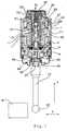
- the probe shown in figure 1 includes support means with a casing 1 - that is hollow, of a substantially cylindrical shape and consists, for example, of a plurality of mutually assembled portions - that defines a longitudinal geometric axis, and a movable arm-set 3 housed and supported in casing 1 .
- Casing 1 includes two reference areas for the movable arm-set, more specifically a substantially frusto-conical seat 5 and an abutment area 7 with plane annular surface.
- the movable arm-set 3 defines a longitudinal axis of symmetry and includes a central reference portion 9 , having substantially the shape of a spherical segment defining a spherical zone, and an abutment flange 11 with annular surface.
- An arm 13 is coupled to the movable arm-set 3 and a feeler 15 is fixed to a free end of arm 13 .
- a helical spring 17 has its ends in abutment against two plane surfaces, integral with the movable arm-set 3 and the casing 1 , respectively, and urges the central reference portion 9 against seat 5 .
- An antirotation device adapted for preventing the rotation of the movable arm-set 3 about the previously mentioned longitudinal axis of symmetry, includes a metal bellows 19 fixed to the arm-set 3 and to a suitable mechanical coupling element, or bucket, 20 , rigidly coupled (for example glued) to casing 1 .
- the bucket 20 has an axial opening 21 and is coupled to casing 1 in such a way to define, with internal surfaces of casing 1 , a recess 22, in communication with the interior of the bellows 19 .
- Two flexible, protective and sealing elements 23 and 24 are arranged between the arm 13 and the casing 1 .
- the contact occurring between feeler 15 and a piece W is detected, after completion of a determined pre-stroke in the longitudinal direction, or, in the case of displacements of the feeler 15 in the transversal direction, at a determined angle between the geometric axis of casing 1 and the axis of symmetry of the arm-set 3 , by means of a detecting device including an electric switch, or microswitch 31 , rigidly coupled to the casing 1 of the probe, for example, by means of a threaded coupling 32 and a ring gasket (or "O-ring”) 30 .
- the microswitch 31 also illustrated in figures 2 and 3 , includes a housing 33 with a longitudinal through hole that defines two cylindrical openings 34 and 35 , with different diameter.
- a closure plate 37 made from insulating material, is fixed to housing 33 by means of rivets or screws 43 and seals - by compressing in a suitable seat a ring gasket (or "O-ring") 36 - an end of the through hole located at opening 34 .
- Plate 37 carries, on its external surface, electrically-conductive tracks 38 and 39 , shown in simplified, cross-sectional form in figure 2 .
- a cylindrical insulating element 41 for example made from plastic, is inserted in the opening 34 and fitted into it and defines an axial guide hole 42 that is consequently located in a substantially concentric position with respect to the longitudinal geometric axis.
- Stationary contacts are achieved by means of two cylindrical conductive bars 44 and 45 , inserted and also fitted into associated mutually parallel transversal seats 46 and 47 defined in part by the insulating element 41 and in part by internal surfaces of the opening 34 , with a disk made from insulating material arranged therebetween, the disk being represented in simplified form by a thick line and identified by reference number 49 in figure 2 .
- the disk 49 electrically insulates the bars 44 and 45 from housing 33 , the latter being made from conductive material.
- a small ball 51 made from electrically-conductive material provides a movable contact and is housed, with small clearance, in hole 42 .
- a compression spring 53 also inserted in hole 42 , urges the small ball 51 against the bars 44 and 45 .
- the microswitch 31 is closed, whereas when the small ball 51 disengages from at least one of bars 44 and 45, the microswitch 31 is open.
- Electrically-conductive elements or wires are housed in longitudinal holes 55 (one is shown in the figures) and electrically connect the bars 44 and 45 to the two conductive tracks 38 and 39 , respectively, that are in turn coupled to the leads of a cable, not shown in the drawings, for connecting - possibly by means of wireless transmission devices, interface devices, etc. - the microswitch 31 to a known control and measurement detecting unit, not shown in the drawing either.
- microswitch 31 includes an actuator, or mechanical transmission device, 61 - for transmitting to the movable contact 51 displacements of the movable arm-set 3 - substantially housed in the cylindrical opening 35 .
- An elongate mechanical body 63 of the transmission device 61 is arranged substantially along a longitudinal direction and includes two abutment ends that protrude from the opposite ends of the opening 35 , for cooperating, respectively, with the small ball 51 in opening 34 and with the end of a transmission pin 25 , that is part of the movable arm-set 3 and is substantially aligned along the longitudinal axis of symmetry.
- the elongate mechanical body 63 includes a pushing stem 65 and a transmission element 67 with substantially spherical surface, the latter being integrally coupled, for example glued, to an end of the former.
- the mechanical transmission device 61 also includes guide elements for the body 63 . More specifically, a bushing 69 - per se known, for example made from sapphire - is internally fixed to the housing 33 , in an intermediate portion with reduced diameter, between the openings 34 and 35 and contributes to guide, with limited clearance, longitudinal displacements of stem 65 near small ball 51.
- the internal surface of opening 35 defines substantially longitudinal guide surfaces that achieve a track 71, said surfaces being, in the embodiment shown in the figures, the lateral ones of a pair of cylindrical bars 70 and 72 arranged side by side, glued at the interior of said opening 35.
- the cylindrical bars 70 and 72 are made, for instance, from zirconium oxide, which is a material that, like sapphire, does not conduct and has specific hardness characteristics, low friction coefficient and high resistance to corrosion and wear.
- housing 33 includes, at the part ending with opening 35, a longitudinal slit 75 where the flat spring 73 is inserted in such a way that a larger end 74 of said spring 73 transversally extends out of the slit 75 ( figure 3 ).
- An annular locking element 76 (for example, an elastic element) is located in a suitable annular seat of the external surface of the housing 33 and prevents the falling of the flat spring 73.
- the bent flat spring 73 cooperates on one side with the housing 33 (transversal thrust between the larger end 74 and the walls of the slit 75 ) and on the other side with the transmission element 67 at a substantially plane portion 77 of its surface - otherwise of a spherical shape - of the latter element.
- the flat spring 73 transversally urges the transmission element 67 against the surfaces of the track 71 with an extremely limited force (for example, just a few grams) that is sufficient for causing the longitudinal displacements of element 67 to be guided by the surfaces of the track 71 free of clearances.
- the specific geometric features and the arrangement of the mechanical body 63 determine that, thanks to the thrust that spring 73 applies to the transmission element 67, the pushing stem 65 leans in a repeatable way on an identical area of the guide surface of the bushing 69, at the opposite side with respect to the track 71, so as to achieve that the longitudinal displacements of the whole body 63 be guided free of clearance and in a repeatable way, according to a defined kinematic trajectory.
- the previously mentioned transmission pin 25 is coupled with a central part of the movable arm-set 3 in an adjustable way. More specifically, pin 25 is integral with a threaded dowel 26 that is in turn screwed into a first threaded end portion of an axial through hole 27 of the arm-set 3.
- the through hole 27 has portions which have different diameter, among them a second threaded end portion, for the coupling of the arm 13, and an intermediate threaded area that houses the body of a closure screw 28.
- the head of the closure screw 28 compresses a ring shaped gasket (or "O-ring”) 29 and seals the axial through hole 27.
- the part of the through hole 27 facing the interior of the probe, the space defined by the bellows 19, the recess 22 and the longitudinal through hole (openings 34 and 35 ) of the housing 33 of the microswitch 31 define a sealingly closed chamber that is full of inert gas, more specifically nitrogen (N 2 ).
- inert gas more specifically nitrogen (N 2 ).
- the gas is inserted in the chamber through hole 27, prior to sealing by means of screw 28 and O-ring 29.
- a probe according to the invention can foresee other embodiments of insofar as the mutual arrangement between movable arm-set 3 and casing 1 in the inoperative condition are concerned.
- Probe A As an alternative to the embodiment including some of the characteristics disclosed in patent No. US-A-5299360 (hereinafter referred to as "Probe A") with clearance between flange 11 and casing 1 in the inoperative condition, there can be foreseen an embodiment in which - in said inoperative condition - the abutment flange 11 rests on the abutment area 7 of the casing 1 (embodiment hereinafter referred to as "Probe B").
- figure 1 wishes to represent both the embodiments (Probes A and B) wherein the clearances of some micrometers - existing in the first case between the abutment flange 11 and area 7 and in the second case between the central portion 9 of the arm-set 3 and the seat 5 of the casing 1 - cannot be seen.
- the movable arm-set 3 When there is no contact between feeler 15 and piece W to be checked, the movable arm-set 3 is supported in casing 1 by the cone-ball type coupling existing between the portion 9 of the arm-set 3 and the seat 5 (Probe A), or between the abutment flange 11 and the abutment area 7 (Probe B) and the end portions of mechanical body 63 face the small ball 51 and, respectively, the end part of the transmission pin 25. At least one of the two elements (small ball 51 and pin 25) is separate from the associated end of body 63 by an extremely limited amount of space, not shown in the figure for the sake of simplicity.
- the electric circuit to which the conductive bars 44, 45 and the small ball 51 belong is closed.
- arm 13 and arm-set 3 displace integrally with respect to casing 1.
- Probe A in Probe A there generally occurs a first, limited rotation of the arm-set 3 enabled by the cone-ball coupling, and the contact that is made substantially at a point between the annular surfaces of the flange 11 and of the area 7 causes a lifting (in other words a displacement including a longitudinal component) of the end surface of the pin 25 further to a tilting of the arm-set 3 about said point of contact.
- contact between feeler 15 and piece W in the transversal direction X determines, in general, a first, limited translation of the arm-set 3 enabled by the clearance existing between the central portion 9 and the seat 5, and a subsequent displacing away of the annular surface of the flange 11 from the surface of the area 7, the two surfaces maintaining contact substantially at a point about which the arm-set 3 tilts.
- the tilting of the arm-set 3 causes a lifting (in other words a displacement including a longitudinal component) of the end surface of the pin 25.
- the end surface of the pin 25 touches the spherical surface of the transmission element 67 and urges the mechanical body 63 that longitudinally translates and is guided free of clearance by the cooperation between element 67 and track 71.
- the latter elements are held one against the other by the thrust of the spring 73 that also causes the transversal repeatable leaning of the stem 65 on a portion of the guide surfaces of bushing 69.
- the pushing stem 65 urges the small ball 51 to oppose the action of the spring 53 and to open the electric circuit.
- the opening of the circuit that indicates the occurrence of contact between feeler 15 and piece W, is monitored in the control and measurement detecting unit.
- the housing 33 of the microswitch 31 is part of a sealingly closed chamber filled with nitrogen.
- nitrogen does not interfere with the metrological performances of the probe, contrarily to what occurs in known devices in which oily fluids are utilized to protect the contacts from oxidation.
- the structure of the microswitch 31 can take other forms with respect to what has been hereinbefore illustrated and described.
- the bars 44 and 45 provides an electric contact, the other being made from non-conductive material, while the small ball 51 is coupled to the conductors in the holes 55 for closing the electric circuit in an inoperative condition and for enabling to detect the opening of the circuit upon the release of the engagement between the small ball 51 and the conductive bar (44 or 45).
- a probe with the microswitch 31 shown in the figures can include, or not include, nitrogen or other inert gas in the sealingly closed chamber.
- Probes utilizing similar electric-switch detecting devices also fall within the scope of the invention even if they have important structural differences with respect to the embodiments of figure 1 (Probe A and Probe B) that can regard, for example, the support of the arm-set 3 in casing 1.
Landscapes
- General Physics & Mathematics (AREA)
- Physics & Mathematics (AREA)
- Measurement Of Length, Angles, Or The Like Using Electric Or Magnetic Means (AREA)
- A Measuring Device Byusing Mechanical Method (AREA)
- Push-Button Switches (AREA)
- Measuring Leads Or Probes (AREA)
- Contacts (AREA)
- Transmitters (AREA)
- Other Investigation Or Analysis Of Materials By Electrical Means (AREA)
- Cold Cathode And The Manufacture (AREA)
- Gloves (AREA)
- Keying Circuit Devices (AREA)
- Mechanical Treatment Of Semiconductor (AREA)
Claims (15)
- Berührungsgeber, der aufweist:ein Gehäuse (1), das eine geometrische Längsachse festlegt,eine bewegbare Armgruppe (3), die im Gehäuse (1) untergebracht ist, das eine Längssymmetrieachse festlegt,einen Arm (13), der mit der bewegbaren Armgruppe (3) starr verbunden ist, wobei ein Ende aus dem Gehäuse verläuft,einen Taster (15), der mit dem Ende des Arms (13) verbunden ist, undeinen elektrischen Schalter (31), der so aufgebaut ist, dass er Auslenkungen der bewegbaren Armgruppe (3) gegenüber dem Gehäuse (1) abtastet, wobei der elektrische Schalter aufweist:ein Gehäuse (33),zumindest einen ortsfesten Kontakt (44, 45)einen bewegbaren Kontakt (51), undeine mechanische Übertragungseinrichtung (61), die so aufgebaut ist, dass sie die Auslenkungen der bewegbaren Armgruppe (3) auf den bewegbaren Kontakt (51) überträgt, wobei die mechanische Übertragungseinrichtung aufweist:einen länglichen, mechanischen Körper (63), der zwischen der bewegbaren Armgruppe (3) und dem bewegbaren Kontakt (51) angeordnet ist, wobei er im Wesentlichen entlang einer Längsrichtung angeordnet und bewegbar ist, undFührungselemente (69-73, 77), die mit dem länglichen, mechanischen Körper (63) zusammenwirken,dadurch gekennzeichnet, dass
die Führungselemente (69-73, 77) im Wesentlichen längliche Führungsflächen (70-72) aufweisen, die in das Gehäuse (33) integriert sind, sowie ein elastisches Druckelement (73) aufweisen, das so ausgebildet ist, dass es den länglichen mechanischen Körper (63) gegen die Führungsflächen (70-72) drückt. - Geber gemäß Anspruch 1, wobei der elektrische Schalter (31) eine Feder (53) aufweist, um den bewegbaren Kontakt (51) gegen den zumindest einen ortsfesten Kontakt (44, 45) zu drücken.
- Geber gemäß Anspruch 2, wobei der elektrische Schalter (31) zumindest zwei ortsfeste Kontakte (44, 45) aufweist, wobei die Feder (53) so ausgebildet ist, dass sie den bewegbaren Kontakt (51) gegen die zumindest zwei ortsfesten Kontakte (44, 45) drückt.
- Geber gemäß einem der bisherigen Ansprüche, wobei die im Wesentlichen in Längsrichtung verlaufenden Führungsflächen (70-72) eine Bahn (71) bilden, wobei der längliche, mechanische Körper (63) geeignete Flächen aufweist, die so ausgebildet sind, dass sie mit der Bahn (71) zusammenwirken, wobei sie von dem elastischen Druckelement (73) entlang einer Querrichtung gedrückt werden.
- Geber gemäß Anspruch 4, wobei der längliche, mechanische Körper (63) einen Druckstößel (65) sowie ein Übertragungselement (67) aufweist, die integriert miteinander gekuppelt sind, wobei das Übertragungselement (67) jene Flächen bildet, die so ausgebildet sind, dass sie mit der Bahn (71) zusammenwirken.
- Geber gemäß Anspruch 5, wobei das elastische Druckelement (73) zwischen Flächen des Gehäuses (33) und einem im Wesentlichen ebenen Teil (77) des Übertragungselements (67) angeordnet ist, wobei das Übertragungselement (67) eine im Wesentlichen kugelförmige Fläche bildet, die so ausgebildet ist, dass sie mit der Bahn (71) zusammenwirkt.
- Geber gemäß Anspruch 6, wobei das elastische Druckelement eine gebogene Flachfeder (73) aufweist.
- Geber gemäß Anspruch 7, wobei das Gehäuse (33) des elektrischen Schalters (31) einen in Längsrichtung verlaufenden Schlitz (75) aufweist, wobei die gebogene Flachfeder (73) zumindest teilweise in dem in Längsrichtung verlaufenden Schlitz (75) untergebracht und verriegelt ist.
- Geber gemäß Anspruch 8, wobei die gebogene Flachfeder (73) ein vergrößertes Ende (74) bildet, das durch den in Längsrichtung verlaufenden Schlitz (75) teilweise und quer aus dem Gehäuse (33) verläuft, wobei der elektrische Schalter (31) ein ringförmiges Verriegelungselement (76) aufweist, das so ausgebildet ist, dass es mit einer äußeren Fläche des Gehäuses (33) zusammenwirkt, um zu verhindern, dass die gebogene Flachfeder (73) aus dem Gehäuse (33) fällt.
- Geber gemäß einem der Ansprüche von 4 bis 9, wobei die Führungselemente (69-73, 77) ein Paar von zylindrischen Schienen (70, 72) aufweisen, wobei die zylindrischen Schienen (70, 72) die Führungsflächen festlegen, die die Bahn (71) bildet.
- Geber gemäß einem der bisherigen Ansprüche, wobei die bewegbare Armgruppe (3) einen Übertragungsstift (25) aufweist, der im Wesentlichen entlang der Längssymmetrieachse ausgerichtet und einstellbar ist, wobei der Übertragungsstift (25) so ausgebildet ist, dass er infolge von Auslenkungen des Arms (13) mit der mechanischen Übertragungseinrichtung (61) des elektrischen Schalters (31) zusammenwirkt.
- Geber gemäß Anspruch 11, wo dieser von einem der Ansprüche von 5 bis 9 abhängt, wobei ein Ende des Übertragungsstifts (25) so ausgebildet ist, dass es infolge von Auslenkungen des Arms (13) das Übertragungselement (67) des länglichen, mechanischen Körpers (63) berührt.
- Geber gemäß einem der Ansprüche von 1 bis 12, wobei die bewegbare Armgruppe (3) im Gehäuse (1) mit Hilfe einer Kegel/Kugel-Kupplung (9, 5) gehalten wird, wobei die bewegbare Armgruppe und das Gehäuse Ringflächen (7, 11) bilden, die so ausgebildet sind, dass sie sich gegenseitig berühren, wobei sie infolge von Auslenkungen des Arms (13) Längsauslenkungen der bewegbaren Armgruppe (3) hervorrufen, die dafür geeignet sind, dass sie mit Hilfe der mechanischen Übertragungseinrichtung (61) zum bewegbaren Kontakt (51) des elektrischen Schalters (31) übertragen werden.
- Geber gemäß einem der Ansprüche von 1 bis 12, wobei die bewegbare Armgruppe (3) im Gehäuse (1) von einer Kupplung zwischen den ebenen Ringflächen (7, 11) gehalten wird, wobei die bewegbare Armgruppe (3) und das Gehäuse (1) einen im Wesentlichen kugelförmigen Teil (9) bzw. einen im Wesentlichen kegelstumpfförmigen Sitz (5) bilden, die so ausgebildet sind, dass sie sich gegenseitig berühren, wobei infolge von Auslenkungen des Arms (13) ein teilweises Ausrasten zwischen den ebenen Ringflächen (7, 11) und damit Längsauslenkungen der bewegbaren Armgruppe (3) hervorgerufen werden, die dafür geeignet sind, dass sie mit Hilfe der mechanischen Übertragungseinrichtung (61) auf den bewegbaren Kontakt (51) des elektrischen Schalters (31) übertagen werden.
- Geber gemäß einem der bisherigen Ansprüche, wobei das Gehäuse (1) eine abgedichtet verschlossene Kammer (19, 22, 34, 35) umschließt, die mit einem inerten Gas gefüllt ist, wobei der elektrische Schalter (31) in der abgedichtet verschlossenen Kammer (19, 22, 34, 35) angeordnet ist.
Applications Claiming Priority (3)
| Application Number | Priority Date | Filing Date | Title |
|---|---|---|---|
| ITBO20020628 | 2002-10-07 | ||
| IT000628A ITBO20020628A1 (it) | 2002-10-07 | 2002-10-07 | Sonda di tastaggio |
| PCT/EP2003/010806 WO2004031685A1 (en) | 2002-10-07 | 2003-09-29 | Touch probe with guided transmission device |
Publications (2)
| Publication Number | Publication Date |
|---|---|
| EP1552242A1 EP1552242A1 (de) | 2005-07-13 |
| EP1552242B1 true EP1552242B1 (de) | 2009-03-04 |
Family
ID=32051210
Family Applications (2)
| Application Number | Title | Priority Date | Filing Date |
|---|---|---|---|
| EP03798923A Expired - Lifetime EP1556664B1 (de) | 2002-10-07 | 2003-09-29 | Berührungssonde mit einem schalter mit durch inertgas gestützten kontakten |
| EP03750655A Expired - Lifetime EP1552242B1 (de) | 2002-10-07 | 2003-09-29 | Tastkopf mit geführtem übertragungsteil |
Family Applications Before (1)
| Application Number | Title | Priority Date | Filing Date |
|---|---|---|---|
| EP03798923A Expired - Lifetime EP1556664B1 (de) | 2002-10-07 | 2003-09-29 | Berührungssonde mit einem schalter mit durch inertgas gestützten kontakten |
Country Status (10)
| Country | Link |
|---|---|
| US (1) | US7159327B2 (de) |
| EP (2) | EP1556664B1 (de) |
| JP (2) | JP4304156B2 (de) |
| CN (2) | CN100348942C (de) |
| AT (2) | ATE424546T1 (de) |
| AU (2) | AU2003270290A1 (de) |
| DE (2) | DE60326479D1 (de) |
| ES (2) | ES2319404T3 (de) |
| IT (1) | ITBO20020628A1 (de) |
| WO (2) | WO2004031684A1 (de) |
Families Citing this family (14)
| Publication number | Priority date | Publication date | Assignee | Title |
|---|---|---|---|---|
| US7168179B2 (en) * | 2003-09-29 | 2007-01-30 | Marposs Societa ' Per Azioni | Touch probe comprising a switch with contacts protected by inert gas |
| KR100928609B1 (ko) * | 2006-05-18 | 2009-11-26 | 파나소닉 주식회사 | 형상측정 장치용 프로브 및 형상측정 장치 |
| US7421795B2 (en) * | 2006-08-04 | 2008-09-09 | Seagate Technology Llc | Sapphire alignment fixture |
| JP4291849B2 (ja) * | 2006-12-20 | 2009-07-08 | パナソニック株式会社 | 三次元測定プローブ |
| US7885786B2 (en) * | 2008-10-15 | 2011-02-08 | Seagate Technology Llc | Sleeve cone quality measurement system and method |
| CN101936696A (zh) * | 2010-08-23 | 2011-01-05 | 永城煤电控股集团有限公司 | 水泵平衡盘间隙测试装置 |
| IT1403845B1 (it) * | 2010-10-29 | 2013-11-08 | Marposs Spa | Sonda di tastaggio e relativo metodo di controllo |
| IT1402715B1 (it) * | 2010-10-29 | 2013-09-18 | Marposs Spa | Sonda di tastaggio |
| WO2012098353A1 (en) | 2011-01-19 | 2012-07-26 | Renishaw Plc | Analogue measurement probe for a machine tool apparatus and method of operation |
| EP2657642A1 (de) | 2012-04-24 | 2013-10-30 | Hexagon Technology Center GmbH | Sensorelement für eine Messmaschine, insbesondere eine Koordinatenmessmaschine |
| JP5984648B2 (ja) * | 2012-12-03 | 2016-09-06 | 三菱重工業株式会社 | クリアランス計測システム及びクリアランス計測方法 |
| CN110547857B (zh) * | 2018-05-30 | 2025-02-18 | 蔡衡 | 三维房间隔穿刺组件 |
| CN110970254B (zh) * | 2020-01-03 | 2025-02-28 | 长春振宇机电成套有限公司 | 球头开关 |
| CN112902837A (zh) * | 2020-12-29 | 2021-06-04 | 山西裕鼎精密科技有限公司 | 刀检仪以及应用于所述刀检仪的刀检方法 |
Family Cites Families (14)
| Publication number | Priority date | Publication date | Assignee | Title |
|---|---|---|---|---|
| DE3229992C2 (de) * | 1982-08-12 | 1986-02-06 | Dr. Johannes Heidenhain Gmbh, 8225 Traunreut | Mehrkoordinaten-Tastkopf |
| DE3375507D1 (en) * | 1982-11-05 | 1988-03-03 | Traub Ag | Caliper |
| GB2145523A (en) * | 1983-08-26 | 1985-03-27 | Gte Valeron Corp | Coatings for contacts of a touch probe |
| CN1005168B (zh) * | 1985-09-21 | 1989-09-13 | 株式会社三丰制作所 | 接触信号测头 |
| US4789762A (en) * | 1988-02-09 | 1988-12-06 | Aerodyne Controls Corporation | Miniature multiplanar acceleration switch |
| IT1238266B (it) * | 1990-03-06 | 1993-07-12 | Marposs Spa | Testa per il controllo di dimensioni lineari di pezzi. |
| WO1992009862A1 (en) * | 1990-11-24 | 1992-06-11 | Renishaw Plc | Touch probe |
| EP0695412A1 (de) * | 1994-02-18 | 1996-02-07 | Renishaw plc | Messsonde |
| IT1305536B1 (it) * | 1998-09-21 | 2001-05-09 | Marposs Spa | Testata per il controllo di dimensioni lineari di pezzi meccanici |
| JP2002174560A (ja) * | 2000-12-07 | 2002-06-21 | Techno Excel Co Ltd | 変位センサ |
| WO2002103282A1 (de) * | 2001-06-18 | 2002-12-27 | Franz Haimer Maschinenbau Kg | Mehrkoordinaten-tastmessgerät |
| DE60129570T2 (de) * | 2001-11-30 | 2008-04-17 | Tesa Sa | Tastsonde und Verfahren zu deren Zusammensetzung |
| EP1443301B1 (de) * | 2003-01-29 | 2010-02-10 | Tesa SA | Lenkbarer Taststift |
| EP1666833B1 (de) * | 2004-12-01 | 2008-01-23 | Tesa SA | Motorisierter und orientierbarer Messkopf |
-
2002
- 2002-10-07 IT IT000628A patent/ITBO20020628A1/it unknown
-
2003
- 2003-09-29 AT AT03798923T patent/ATE424546T1/de active
- 2003-09-29 AT AT03750655T patent/ATE424545T1/de active
- 2003-09-29 CN CNB038238896A patent/CN100348942C/zh not_active Expired - Fee Related
- 2003-09-29 WO PCT/EP2003/010805 patent/WO2004031684A1/en not_active Ceased
- 2003-09-29 WO PCT/EP2003/010806 patent/WO2004031685A1/en not_active Ceased
- 2003-09-29 EP EP03798923A patent/EP1556664B1/de not_active Expired - Lifetime
- 2003-09-29 AU AU2003270290A patent/AU2003270290A1/en not_active Abandoned
- 2003-09-29 ES ES03750655T patent/ES2319404T3/es not_active Expired - Lifetime
- 2003-09-29 JP JP2004540741A patent/JP4304156B2/ja not_active Expired - Fee Related
- 2003-09-29 CN CNB038238888A patent/CN100559112C/zh not_active Expired - Fee Related
- 2003-09-29 EP EP03750655A patent/EP1552242B1/de not_active Expired - Lifetime
- 2003-09-29 AU AU2003276004A patent/AU2003276004A1/en not_active Abandoned
- 2003-09-29 DE DE60326479T patent/DE60326479D1/de not_active Expired - Lifetime
- 2003-09-29 ES ES03798923T patent/ES2319413T3/es not_active Expired - Lifetime
- 2003-09-29 DE DE60326477T patent/DE60326477D1/de not_active Expired - Lifetime
- 2003-09-29 US US10/529,140 patent/US7159327B2/en not_active Expired - Lifetime
- 2003-09-29 JP JP2004540740A patent/JP4578974B2/ja not_active Expired - Fee Related
Also Published As
| Publication number | Publication date |
|---|---|
| US7159327B2 (en) | 2007-01-09 |
| EP1552242A1 (de) | 2005-07-13 |
| ES2319413T3 (es) | 2009-05-07 |
| ES2319404T3 (es) | 2009-05-07 |
| JP2006502536A (ja) | 2006-01-19 |
| JP4304156B2 (ja) | 2009-07-29 |
| AU2003276004A1 (en) | 2004-04-23 |
| JP2006502380A (ja) | 2006-01-19 |
| WO2004031684A1 (en) | 2004-04-15 |
| JP4578974B2 (ja) | 2010-11-10 |
| ITBO20020628A1 (it) | 2004-04-08 |
| CN1688862A (zh) | 2005-10-26 |
| DE60326479D1 (de) | 2009-04-16 |
| CN100559112C (zh) | 2009-11-11 |
| WO2004031685A1 (en) | 2004-04-15 |
| DE60326477D1 (de) | 2009-04-16 |
| ATE424546T1 (de) | 2009-03-15 |
| EP1556664A1 (de) | 2005-07-27 |
| AU2003270290A1 (en) | 2004-04-23 |
| US20050268478A1 (en) | 2005-12-08 |
| EP1556664B1 (de) | 2009-03-04 |
| CN1688863A (zh) | 2005-10-26 |
| ATE424545T1 (de) | 2009-03-15 |
| CN100348942C (zh) | 2007-11-14 |
Similar Documents
| Publication | Publication Date | Title |
|---|---|---|
| EP1552242B1 (de) | Tastkopf mit geführtem übertragungsteil | |
| US4301338A (en) | Contact-sensing probe | |
| EP1336816B1 (de) | Messkopf zum Kontrollieren linearer Dimensionen mit einstellbarer Feder | |
| US7665222B2 (en) | Gauge for checking radial dimensions of mechanical pieces | |
| KR20090053691A (ko) | 센서 | |
| GB2121966A (en) | Touch probe apparatus | |
| US7168179B2 (en) | Touch probe comprising a switch with contacts protected by inert gas | |
| EP0476076B1 (de) | Tastkopf zur kontrolle von linearen dimensionen | |
| US5157845A (en) | Device for checking linear dimensions of parts | |
| WO2000017602A1 (en) | Head for the linear dimension checking of mechanical pieces | |
| CN101473186A (zh) | 汽缸的冲程位置测量装置 | |
| JPS58100701A (ja) | 線寸法を検査するための検出器 | |
| US3673695A (en) | Non-tilting probe | |
| CN112179302B (zh) | 位置度测量装置和位置度测量方法 | |
| US4603482A (en) | Probe shield | |
| CN113263355A (zh) | 对刀测量装置 | |
| US4496807A (en) | Touch signal probe | |
| RU2856298C1 (ru) | Измерительный датчик для сканирования поверхности в труднодоступных местах | |
| CN221099581U (zh) | 测量工具及具有其的断路器 |
Legal Events
| Date | Code | Title | Description |
|---|---|---|---|
| PUAI | Public reference made under article 153(3) epc to a published international application that has entered the european phase |
Free format text: ORIGINAL CODE: 0009012 |
|
| 17P | Request for examination filed |
Effective date: 20050509 |
|
| AK | Designated contracting states |
Kind code of ref document: A1 Designated state(s): AT BE BG CH CY CZ DE DK EE ES FI FR GB GR HU IE IT LI LU MC NL PT RO SE SI SK TR |
|
| AX | Request for extension of the european patent |
Extension state: AL LT LV MK |
|
| DAX | Request for extension of the european patent (deleted) | ||
| RIN1 | Information on inventor provided before grant (corrected) |
Inventor name: BARUCHELLO, ROBERTO Inventor name: FORNI, ALESSANDRO |
|
| REG | Reference to a national code |
Ref country code: SE Ref legal event code: TRGR |
|
| RAP1 | Party data changed (applicant data changed or rights of an application transferred) |
Owner name: MARPOSS SOCIETA' PER AZIONI |
|
| GRAP | Despatch of communication of intention to grant a patent |
Free format text: ORIGINAL CODE: EPIDOSNIGR1 |
|
| GRAS | Grant fee paid |
Free format text: ORIGINAL CODE: EPIDOSNIGR3 |
|
| GRAA | (expected) grant |
Free format text: ORIGINAL CODE: 0009210 |
|
| AK | Designated contracting states |
Kind code of ref document: B1 Designated state(s): AT BE BG CH CY CZ DE DK EE ES FI FR GB GR HU IE IT LI LU MC NL PT RO SE SI SK TR |
|
| REG | Reference to a national code |
Ref country code: GB Ref legal event code: FG4D |
|
| REG | Reference to a national code |
Ref country code: CH Ref legal event code: EP |
|
| REG | Reference to a national code |
Ref country code: IE Ref legal event code: FG4D |
|
| REF | Corresponds to: |
Ref document number: 60326477 Country of ref document: DE Date of ref document: 20090416 Kind code of ref document: P |
|
| REG | Reference to a national code |
Ref country code: ES Ref legal event code: FG2A Ref document number: 2319404 Country of ref document: ES Kind code of ref document: T3 |
|
| PG25 | Lapsed in a contracting state [announced via postgrant information from national office to epo] |
Ref country code: FI Free format text: LAPSE BECAUSE OF FAILURE TO SUBMIT A TRANSLATION OF THE DESCRIPTION OR TO PAY THE FEE WITHIN THE PRESCRIBED TIME-LIMIT Effective date: 20090304 Ref country code: SI Free format text: LAPSE BECAUSE OF FAILURE TO SUBMIT A TRANSLATION OF THE DESCRIPTION OR TO PAY THE FEE WITHIN THE PRESCRIBED TIME-LIMIT Effective date: 20090304 Ref country code: NL Free format text: LAPSE BECAUSE OF FAILURE TO SUBMIT A TRANSLATION OF THE DESCRIPTION OR TO PAY THE FEE WITHIN THE PRESCRIBED TIME-LIMIT Effective date: 20090304 |
|
| NLV1 | Nl: lapsed or annulled due to failure to fulfill the requirements of art. 29p and 29m of the patents act | ||
| PG25 | Lapsed in a contracting state [announced via postgrant information from national office to epo] |
Ref country code: BE Free format text: LAPSE BECAUSE OF FAILURE TO SUBMIT A TRANSLATION OF THE DESCRIPTION OR TO PAY THE FEE WITHIN THE PRESCRIBED TIME-LIMIT Effective date: 20090304 |
|
| PG25 | Lapsed in a contracting state [announced via postgrant information from national office to epo] |
Ref country code: EE Free format text: LAPSE BECAUSE OF FAILURE TO SUBMIT A TRANSLATION OF THE DESCRIPTION OR TO PAY THE FEE WITHIN THE PRESCRIBED TIME-LIMIT Effective date: 20090304 Ref country code: PT Free format text: LAPSE BECAUSE OF FAILURE TO SUBMIT A TRANSLATION OF THE DESCRIPTION OR TO PAY THE FEE WITHIN THE PRESCRIBED TIME-LIMIT Effective date: 20090819 |
|
| PG25 | Lapsed in a contracting state [announced via postgrant information from national office to epo] |
Ref country code: SK Free format text: LAPSE BECAUSE OF FAILURE TO SUBMIT A TRANSLATION OF THE DESCRIPTION OR TO PAY THE FEE WITHIN THE PRESCRIBED TIME-LIMIT Effective date: 20090304 Ref country code: RO Free format text: LAPSE BECAUSE OF FAILURE TO SUBMIT A TRANSLATION OF THE DESCRIPTION OR TO PAY THE FEE WITHIN THE PRESCRIBED TIME-LIMIT Effective date: 20090304 |
|
| PLBE | No opposition filed within time limit |
Free format text: ORIGINAL CODE: 0009261 |
|
| STAA | Information on the status of an ep patent application or granted ep patent |
Free format text: STATUS: NO OPPOSITION FILED WITHIN TIME LIMIT |
|
| PG25 | Lapsed in a contracting state [announced via postgrant information from national office to epo] |
Ref country code: DK Free format text: LAPSE BECAUSE OF FAILURE TO SUBMIT A TRANSLATION OF THE DESCRIPTION OR TO PAY THE FEE WITHIN THE PRESCRIBED TIME-LIMIT Effective date: 20090304 Ref country code: BG Free format text: LAPSE BECAUSE OF FAILURE TO SUBMIT A TRANSLATION OF THE DESCRIPTION OR TO PAY THE FEE WITHIN THE PRESCRIBED TIME-LIMIT Effective date: 20090604 |
|
| 26N | No opposition filed |
Effective date: 20091207 |
|
| PG25 | Lapsed in a contracting state [announced via postgrant information from national office to epo] |
Ref country code: MC Free format text: LAPSE BECAUSE OF NON-PAYMENT OF DUE FEES Effective date: 20090930 |
|
| REG | Reference to a national code |
Ref country code: IE Ref legal event code: MM4A |
|
| PG25 | Lapsed in a contracting state [announced via postgrant information from national office to epo] |
Ref country code: IE Free format text: LAPSE BECAUSE OF NON-PAYMENT OF DUE FEES Effective date: 20090929 |
|
| PG25 | Lapsed in a contracting state [announced via postgrant information from national office to epo] |
Ref country code: GR Free format text: LAPSE BECAUSE OF FAILURE TO SUBMIT A TRANSLATION OF THE DESCRIPTION OR TO PAY THE FEE WITHIN THE PRESCRIBED TIME-LIMIT Effective date: 20090605 |
|
| PGFP | Annual fee paid to national office [announced via postgrant information from national office to epo] |
Ref country code: TR Payment date: 20100928 Year of fee payment: 8 |
|
| PG25 | Lapsed in a contracting state [announced via postgrant information from national office to epo] |
Ref country code: LU Free format text: LAPSE BECAUSE OF NON-PAYMENT OF DUE FEES Effective date: 20090929 |
|
| PG25 | Lapsed in a contracting state [announced via postgrant information from national office to epo] |
Ref country code: HU Free format text: LAPSE BECAUSE OF FAILURE TO SUBMIT A TRANSLATION OF THE DESCRIPTION OR TO PAY THE FEE WITHIN THE PRESCRIBED TIME-LIMIT Effective date: 20090905 |
|
| PG25 | Lapsed in a contracting state [announced via postgrant information from national office to epo] |
Ref country code: CY Free format text: LAPSE BECAUSE OF FAILURE TO SUBMIT A TRANSLATION OF THE DESCRIPTION OR TO PAY THE FEE WITHIN THE PRESCRIBED TIME-LIMIT Effective date: 20090304 |
|
| PGFP | Annual fee paid to national office [announced via postgrant information from national office to epo] |
Ref country code: CH Payment date: 20110922 Year of fee payment: 9 |
|
| PGFP | Annual fee paid to national office [announced via postgrant information from national office to epo] |
Ref country code: SE Payment date: 20110920 Year of fee payment: 9 Ref country code: FR Payment date: 20110927 Year of fee payment: 9 Ref country code: CZ Payment date: 20110822 Year of fee payment: 9 Ref country code: AT Payment date: 20110920 Year of fee payment: 9 Ref country code: ES Payment date: 20110926 Year of fee payment: 9 |
|
| PG25 | Lapsed in a contracting state [announced via postgrant information from national office to epo] |
Ref country code: CZ Free format text: LAPSE BECAUSE OF NON-PAYMENT OF DUE FEES Effective date: 20120929 Ref country code: SE Free format text: LAPSE BECAUSE OF NON-PAYMENT OF DUE FEES Effective date: 20120930 |
|
| REG | Reference to a national code |
Ref country code: SE Ref legal event code: EUG Ref country code: CH Ref legal event code: PL |
|
| REG | Reference to a national code |
Ref country code: AT Ref legal event code: MM01 Ref document number: 424545 Country of ref document: AT Kind code of ref document: T Effective date: 20120929 |
|
| REG | Reference to a national code |
Ref country code: FR Ref legal event code: ST Effective date: 20130531 |
|
| PG25 | Lapsed in a contracting state [announced via postgrant information from national office to epo] |
Ref country code: CH Free format text: LAPSE BECAUSE OF NON-PAYMENT OF DUE FEES Effective date: 20120930 Ref country code: LI Free format text: LAPSE BECAUSE OF NON-PAYMENT OF DUE FEES Effective date: 20120930 Ref country code: AT Free format text: LAPSE BECAUSE OF NON-PAYMENT OF DUE FEES Effective date: 20120929 |
|
| PG25 | Lapsed in a contracting state [announced via postgrant information from national office to epo] |
Ref country code: FR Free format text: LAPSE BECAUSE OF NON-PAYMENT OF DUE FEES Effective date: 20121001 |
|
| REG | Reference to a national code |
Ref country code: ES Ref legal event code: FD2A Effective date: 20131022 |
|
| PG25 | Lapsed in a contracting state [announced via postgrant information from national office to epo] |
Ref country code: TR Free format text: LAPSE BECAUSE OF NON-PAYMENT OF DUE FEES Effective date: 20120928 |
|
| PG25 | Lapsed in a contracting state [announced via postgrant information from national office to epo] |
Ref country code: ES Free format text: LAPSE BECAUSE OF NON-PAYMENT OF DUE FEES Effective date: 20120930 |
|
| PGFP | Annual fee paid to national office [announced via postgrant information from national office to epo] |
Ref country code: GB Payment date: 20180924 Year of fee payment: 16 |
|
| PGFP | Annual fee paid to national office [announced via postgrant information from national office to epo] |
Ref country code: DE Payment date: 20181001 Year of fee payment: 16 |
|
| PGFP | Annual fee paid to national office [announced via postgrant information from national office to epo] |
Ref country code: IT Payment date: 20180928 Year of fee payment: 16 |
|
| REG | Reference to a national code |
Ref country code: DE Ref legal event code: R119 Ref document number: 60326477 Country of ref document: DE |
|
| PG25 | Lapsed in a contracting state [announced via postgrant information from national office to epo] |
Ref country code: DE Free format text: LAPSE BECAUSE OF NON-PAYMENT OF DUE FEES Effective date: 20200401 |
|
| PG25 | Lapsed in a contracting state [announced via postgrant information from national office to epo] |
Ref country code: IT Free format text: LAPSE BECAUSE OF NON-PAYMENT OF DUE FEES Effective date: 20190929 |
|
| GBPC | Gb: european patent ceased through non-payment of renewal fee |
Effective date: 20190929 |
|
| PG25 | Lapsed in a contracting state [announced via postgrant information from national office to epo] |
Ref country code: GB Free format text: LAPSE BECAUSE OF NON-PAYMENT OF DUE FEES Effective date: 20190929 |