EP1552242B1 - Touch probe with guided transmission device - Google Patents
Touch probe with guided transmission device Download PDFInfo
- Publication number
- EP1552242B1 EP1552242B1 EP03750655A EP03750655A EP1552242B1 EP 1552242 B1 EP1552242 B1 EP 1552242B1 EP 03750655 A EP03750655 A EP 03750655A EP 03750655 A EP03750655 A EP 03750655A EP 1552242 B1 EP1552242 B1 EP 1552242B1
- Authority
- EP
- European Patent Office
- Prior art keywords
- arm
- casing
- probe according
- movable arm
- longitudinal
- Prior art date
- Legal status (The legal status is an assumption and is not a legal conclusion. Google has not performed a legal analysis and makes no representation as to the accuracy of the status listed.)
- Expired - Lifetime
Links
- 239000000523 sample Substances 0.000 title claims abstract description 56
- 230000005540 biological transmission Effects 0.000 title claims abstract description 23
- 238000006073 displacement reaction Methods 0.000 claims abstract description 25
- 230000009347 mechanical transmission Effects 0.000 claims abstract description 11
- 230000008878 coupling Effects 0.000 claims description 11
- 238000010168 coupling process Methods 0.000 claims description 11
- 238000005859 coupling reaction Methods 0.000 claims description 11
- 239000011261 inert gas Substances 0.000 claims description 6
- IJGRMHOSHXDMSA-UHFFFAOYSA-N Atomic nitrogen Chemical compound N#N IJGRMHOSHXDMSA-UHFFFAOYSA-N 0.000 description 9
- 229910052757 nitrogen Inorganic materials 0.000 description 4
- QVGXLLKOCUKJST-UHFFFAOYSA-N atomic oxygen Chemical compound [O] QVGXLLKOCUKJST-UHFFFAOYSA-N 0.000 description 3
- 239000004020 conductor Substances 0.000 description 3
- 230000007547 defect Effects 0.000 description 3
- 239000012530 fluid Substances 0.000 description 3
- 230000006872 improvement Effects 0.000 description 3
- 238000005259 measurement Methods 0.000 description 3
- 230000003647 oxidation Effects 0.000 description 3
- 238000007254 oxidation reaction Methods 0.000 description 3
- 239000001301 oxygen Substances 0.000 description 3
- 229910052760 oxygen Inorganic materials 0.000 description 3
- 238000013519 translation Methods 0.000 description 3
- XKRFYHLGVUSROY-UHFFFAOYSA-N Argon Chemical compound [Ar] XKRFYHLGVUSROY-UHFFFAOYSA-N 0.000 description 2
- 230000009471 action Effects 0.000 description 2
- 230000008901 benefit Effects 0.000 description 2
- 239000011810 insulating material Substances 0.000 description 2
- 238000003754 machining Methods 0.000 description 2
- 238000004519 manufacturing process Methods 0.000 description 2
- 239000000463 material Substances 0.000 description 2
- 238000000034 method Methods 0.000 description 2
- 230000008569 process Effects 0.000 description 2
- 229910052594 sapphire Inorganic materials 0.000 description 2
- 239000010980 sapphire Substances 0.000 description 2
- 238000007789 sealing Methods 0.000 description 2
- 239000000126 substance Substances 0.000 description 2
- XLYOFNOQVPJJNP-UHFFFAOYSA-N water Substances O XLYOFNOQVPJJNP-UHFFFAOYSA-N 0.000 description 2
- 230000004075 alteration Effects 0.000 description 1
- 229910052786 argon Inorganic materials 0.000 description 1
- 238000004891 communication Methods 0.000 description 1
- 230000006835 compression Effects 0.000 description 1
- 238000007906 compression Methods 0.000 description 1
- 230000007797 corrosion Effects 0.000 description 1
- 238000005260 corrosion Methods 0.000 description 1
- 230000000694 effects Effects 0.000 description 1
- 230000008030 elimination Effects 0.000 description 1
- 238000003379 elimination reaction Methods 0.000 description 1
- 239000007789 gas Substances 0.000 description 1
- 239000001307 helium Substances 0.000 description 1
- 229910052734 helium Inorganic materials 0.000 description 1
- SWQJXJOGLNCZEY-UHFFFAOYSA-N helium atom Chemical compound [He] SWQJXJOGLNCZEY-UHFFFAOYSA-N 0.000 description 1
- 238000003780 insertion Methods 0.000 description 1
- 230000037431 insertion Effects 0.000 description 1
- 230000001050 lubricating effect Effects 0.000 description 1
- 229910052751 metal Inorganic materials 0.000 description 1
- 239000002184 metal Substances 0.000 description 1
- 238000012806 monitoring device Methods 0.000 description 1
- 239000012811 non-conductive material Substances 0.000 description 1
- RVTZCBVAJQQJTK-UHFFFAOYSA-N oxygen(2-);zirconium(4+) Chemical compound [O-2].[O-2].[Zr+4] RVTZCBVAJQQJTK-UHFFFAOYSA-N 0.000 description 1
- 230000002265 prevention Effects 0.000 description 1
- 230000001681 protective effect Effects 0.000 description 1
- 229910001928 zirconium oxide Inorganic materials 0.000 description 1
Images

Classifications
-
- G—PHYSICS
- G01—MEASURING; TESTING
- G01B—MEASURING LENGTH, THICKNESS OR SIMILAR LINEAR DIMENSIONS; MEASURING ANGLES; MEASURING AREAS; MEASURING IRREGULARITIES OF SURFACES OR CONTOURS
- G01B7/00—Measuring arrangements characterised by the use of electric or magnetic techniques
- G01B7/004—Measuring arrangements characterised by the use of electric or magnetic techniques for measuring coordinates of points
- G01B7/008—Measuring arrangements characterised by the use of electric or magnetic techniques for measuring coordinates of points using coordinate measuring machines
- G01B7/012—Contact-making feeler heads therefor
Definitions
- the invention relates to a touch probe, including a casing that defines a longitudinal geometric axis, a movable arm-set housed in the casing, that defines a longitudinal symmetry axis, an arm rigidly coupled to the movable arm-set, with an end extending out of the casing, a feeler coupled to said end of the arm, and an electric switch adapted for detecting displacements of the movable arm-set with respect to the casing and including a housing, at least a stationary contact, a movable contact, and a mechanical transmission device adapted for transmitting displacements of the movable arm-set to the movable contact, the mechanical transmission device including an elongate mechanical body, located between the movable arm-set and the movable contact, arranged and movable substantially along a longitudinal direction, and guide elements for cooperating with the elongate mechanical body.
- Touch probes with movable arm-sets that carry feelers are utilized in coordinate measuring machines and in machine tools, more specifically in machining centers and lathes, for carrying out checkings on machined or to be machined pieces, on the tools, on the machine tables, etc.
- contact between feeler and, for example, a mechanical piece is monitored by suitable devices which detect specific displacements of the movable arm-set with respect to a casing and control the reading of transducers associated with the machine slides, that provide measurement values with respect to a reference position or origin.
- a probe detecting and monitoring device can foresee the utilization of an electric circuit and of (at least) an associated switch that, actuated in a mechanical way as a result of displacements occurring between the movable arm and the casing, causes the closure or, more frequently, the opening of the circuit.
- the U.S. patent No. US-A-5299360 discloses probes according to the preamble of claim 1, each including a microswitch with a stem having a free end that cooperates with the movable arm-set. More specifically, in each of said probes, the coupling between the movable arm-set and the stationary casing is such that, further to displacements of the feeler in a longitudinal direction or in a transversal direction, there occurs the lifting of an abutment surface of the movable arm-set that is near the microswitch and the consequent thrust on the stem, the disengagement of the contacts and the opening of the electric circuit.
- touch probes are required to have is a high standard of repeatability i.e. a close correlation between specific positions taken by the feeler and the opening of the electric circuit.
- the mutual arrangement among the component parts of the switch is accurately defined insofar as, among other things, the aligning - along a longitudinal axis of the thrust spring - of the movable contact, generally ball shaped, and of the stem is concerned.
- the probes disclosed in patent No. US-A-5299360 guarantee good repeatability, an absolutely perfect alignment between the component parts of the switch is not however possible.
- variations in the mutual positions of the stem and of the other component parts of the microswitch due to clearances in the longitudinal guide system and/or possible rotations of the stem about its axis, even though of extremely small entity, can negatively affect the repeatability of the probe. This is especially true in recent high precision applications in which it is required that the repeatability errors be particularly small, considerably smaller than 1 ⁇ m.
- An object of the present invention is to provide touch probes that, by maintaining the known structure substantially unaltered and by utilizing extremely simple and economic means, attain an improvement in the performance and, in particular, an extremely high standard of repeatability.
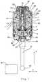
- the probe shown in figure 1 includes support means with a casing 1 - that is hollow, of a substantially cylindrical shape and consists, for example, of a plurality of mutually assembled portions - that defines a longitudinal geometric axis, and a movable arm-set 3 housed and supported in casing 1 .
- Casing 1 includes two reference areas for the movable arm-set, more specifically a substantially frusto-conical seat 5 and an abutment area 7 with plane annular surface.
- the movable arm-set 3 defines a longitudinal axis of symmetry and includes a central reference portion 9 , having substantially the shape of a spherical segment defining a spherical zone, and an abutment flange 11 with annular surface.
- An arm 13 is coupled to the movable arm-set 3 and a feeler 15 is fixed to a free end of arm 13 .
- a helical spring 17 has its ends in abutment against two plane surfaces, integral with the movable arm-set 3 and the casing 1 , respectively, and urges the central reference portion 9 against seat 5 .
- An antirotation device adapted for preventing the rotation of the movable arm-set 3 about the previously mentioned longitudinal axis of symmetry, includes a metal bellows 19 fixed to the arm-set 3 and to a suitable mechanical coupling element, or bucket, 20 , rigidly coupled (for example glued) to casing 1 .
- the bucket 20 has an axial opening 21 and is coupled to casing 1 in such a way to define, with internal surfaces of casing 1 , a recess 22, in communication with the interior of the bellows 19 .
- Two flexible, protective and sealing elements 23 and 24 are arranged between the arm 13 and the casing 1 .
- the contact occurring between feeler 15 and a piece W is detected, after completion of a determined pre-stroke in the longitudinal direction, or, in the case of displacements of the feeler 15 in the transversal direction, at a determined angle between the geometric axis of casing 1 and the axis of symmetry of the arm-set 3 , by means of a detecting device including an electric switch, or microswitch 31 , rigidly coupled to the casing 1 of the probe, for example, by means of a threaded coupling 32 and a ring gasket (or "O-ring”) 30 .
- the microswitch 31 also illustrated in figures 2 and 3 , includes a housing 33 with a longitudinal through hole that defines two cylindrical openings 34 and 35 , with different diameter.
- a closure plate 37 made from insulating material, is fixed to housing 33 by means of rivets or screws 43 and seals - by compressing in a suitable seat a ring gasket (or "O-ring") 36 - an end of the through hole located at opening 34 .
- Plate 37 carries, on its external surface, electrically-conductive tracks 38 and 39 , shown in simplified, cross-sectional form in figure 2 .
- a cylindrical insulating element 41 for example made from plastic, is inserted in the opening 34 and fitted into it and defines an axial guide hole 42 that is consequently located in a substantially concentric position with respect to the longitudinal geometric axis.
- Stationary contacts are achieved by means of two cylindrical conductive bars 44 and 45 , inserted and also fitted into associated mutually parallel transversal seats 46 and 47 defined in part by the insulating element 41 and in part by internal surfaces of the opening 34 , with a disk made from insulating material arranged therebetween, the disk being represented in simplified form by a thick line and identified by reference number 49 in figure 2 .
- the disk 49 electrically insulates the bars 44 and 45 from housing 33 , the latter being made from conductive material.
- a small ball 51 made from electrically-conductive material provides a movable contact and is housed, with small clearance, in hole 42 .
- a compression spring 53 also inserted in hole 42 , urges the small ball 51 against the bars 44 and 45 .
- the microswitch 31 is closed, whereas when the small ball 51 disengages from at least one of bars 44 and 45, the microswitch 31 is open.
- Electrically-conductive elements or wires are housed in longitudinal holes 55 (one is shown in the figures) and electrically connect the bars 44 and 45 to the two conductive tracks 38 and 39 , respectively, that are in turn coupled to the leads of a cable, not shown in the drawings, for connecting - possibly by means of wireless transmission devices, interface devices, etc. - the microswitch 31 to a known control and measurement detecting unit, not shown in the drawing either.
- microswitch 31 includes an actuator, or mechanical transmission device, 61 - for transmitting to the movable contact 51 displacements of the movable arm-set 3 - substantially housed in the cylindrical opening 35 .
- An elongate mechanical body 63 of the transmission device 61 is arranged substantially along a longitudinal direction and includes two abutment ends that protrude from the opposite ends of the opening 35 , for cooperating, respectively, with the small ball 51 in opening 34 and with the end of a transmission pin 25 , that is part of the movable arm-set 3 and is substantially aligned along the longitudinal axis of symmetry.
- the elongate mechanical body 63 includes a pushing stem 65 and a transmission element 67 with substantially spherical surface, the latter being integrally coupled, for example glued, to an end of the former.
- the mechanical transmission device 61 also includes guide elements for the body 63 . More specifically, a bushing 69 - per se known, for example made from sapphire - is internally fixed to the housing 33 , in an intermediate portion with reduced diameter, between the openings 34 and 35 and contributes to guide, with limited clearance, longitudinal displacements of stem 65 near small ball 51.
- the internal surface of opening 35 defines substantially longitudinal guide surfaces that achieve a track 71, said surfaces being, in the embodiment shown in the figures, the lateral ones of a pair of cylindrical bars 70 and 72 arranged side by side, glued at the interior of said opening 35.
- the cylindrical bars 70 and 72 are made, for instance, from zirconium oxide, which is a material that, like sapphire, does not conduct and has specific hardness characteristics, low friction coefficient and high resistance to corrosion and wear.
- housing 33 includes, at the part ending with opening 35, a longitudinal slit 75 where the flat spring 73 is inserted in such a way that a larger end 74 of said spring 73 transversally extends out of the slit 75 ( figure 3 ).
- An annular locking element 76 (for example, an elastic element) is located in a suitable annular seat of the external surface of the housing 33 and prevents the falling of the flat spring 73.
- the bent flat spring 73 cooperates on one side with the housing 33 (transversal thrust between the larger end 74 and the walls of the slit 75 ) and on the other side with the transmission element 67 at a substantially plane portion 77 of its surface - otherwise of a spherical shape - of the latter element.
- the flat spring 73 transversally urges the transmission element 67 against the surfaces of the track 71 with an extremely limited force (for example, just a few grams) that is sufficient for causing the longitudinal displacements of element 67 to be guided by the surfaces of the track 71 free of clearances.
- the specific geometric features and the arrangement of the mechanical body 63 determine that, thanks to the thrust that spring 73 applies to the transmission element 67, the pushing stem 65 leans in a repeatable way on an identical area of the guide surface of the bushing 69, at the opposite side with respect to the track 71, so as to achieve that the longitudinal displacements of the whole body 63 be guided free of clearance and in a repeatable way, according to a defined kinematic trajectory.
- the previously mentioned transmission pin 25 is coupled with a central part of the movable arm-set 3 in an adjustable way. More specifically, pin 25 is integral with a threaded dowel 26 that is in turn screwed into a first threaded end portion of an axial through hole 27 of the arm-set 3.
- the through hole 27 has portions which have different diameter, among them a second threaded end portion, for the coupling of the arm 13, and an intermediate threaded area that houses the body of a closure screw 28.
- the head of the closure screw 28 compresses a ring shaped gasket (or "O-ring”) 29 and seals the axial through hole 27.
- the part of the through hole 27 facing the interior of the probe, the space defined by the bellows 19, the recess 22 and the longitudinal through hole (openings 34 and 35 ) of the housing 33 of the microswitch 31 define a sealingly closed chamber that is full of inert gas, more specifically nitrogen (N 2 ).
- inert gas more specifically nitrogen (N 2 ).
- the gas is inserted in the chamber through hole 27, prior to sealing by means of screw 28 and O-ring 29.
- a probe according to the invention can foresee other embodiments of insofar as the mutual arrangement between movable arm-set 3 and casing 1 in the inoperative condition are concerned.
- Probe A As an alternative to the embodiment including some of the characteristics disclosed in patent No. US-A-5299360 (hereinafter referred to as "Probe A") with clearance between flange 11 and casing 1 in the inoperative condition, there can be foreseen an embodiment in which - in said inoperative condition - the abutment flange 11 rests on the abutment area 7 of the casing 1 (embodiment hereinafter referred to as "Probe B").
- figure 1 wishes to represent both the embodiments (Probes A and B) wherein the clearances of some micrometers - existing in the first case between the abutment flange 11 and area 7 and in the second case between the central portion 9 of the arm-set 3 and the seat 5 of the casing 1 - cannot be seen.
- the movable arm-set 3 When there is no contact between feeler 15 and piece W to be checked, the movable arm-set 3 is supported in casing 1 by the cone-ball type coupling existing between the portion 9 of the arm-set 3 and the seat 5 (Probe A), or between the abutment flange 11 and the abutment area 7 (Probe B) and the end portions of mechanical body 63 face the small ball 51 and, respectively, the end part of the transmission pin 25. At least one of the two elements (small ball 51 and pin 25) is separate from the associated end of body 63 by an extremely limited amount of space, not shown in the figure for the sake of simplicity.
- the electric circuit to which the conductive bars 44, 45 and the small ball 51 belong is closed.
- arm 13 and arm-set 3 displace integrally with respect to casing 1.
- Probe A in Probe A there generally occurs a first, limited rotation of the arm-set 3 enabled by the cone-ball coupling, and the contact that is made substantially at a point between the annular surfaces of the flange 11 and of the area 7 causes a lifting (in other words a displacement including a longitudinal component) of the end surface of the pin 25 further to a tilting of the arm-set 3 about said point of contact.
- contact between feeler 15 and piece W in the transversal direction X determines, in general, a first, limited translation of the arm-set 3 enabled by the clearance existing between the central portion 9 and the seat 5, and a subsequent displacing away of the annular surface of the flange 11 from the surface of the area 7, the two surfaces maintaining contact substantially at a point about which the arm-set 3 tilts.
- the tilting of the arm-set 3 causes a lifting (in other words a displacement including a longitudinal component) of the end surface of the pin 25.
- the end surface of the pin 25 touches the spherical surface of the transmission element 67 and urges the mechanical body 63 that longitudinally translates and is guided free of clearance by the cooperation between element 67 and track 71.
- the latter elements are held one against the other by the thrust of the spring 73 that also causes the transversal repeatable leaning of the stem 65 on a portion of the guide surfaces of bushing 69.
- the pushing stem 65 urges the small ball 51 to oppose the action of the spring 53 and to open the electric circuit.
- the opening of the circuit that indicates the occurrence of contact between feeler 15 and piece W, is monitored in the control and measurement detecting unit.
- the housing 33 of the microswitch 31 is part of a sealingly closed chamber filled with nitrogen.
- nitrogen does not interfere with the metrological performances of the probe, contrarily to what occurs in known devices in which oily fluids are utilized to protect the contacts from oxidation.
- the structure of the microswitch 31 can take other forms with respect to what has been hereinbefore illustrated and described.
- the bars 44 and 45 provides an electric contact, the other being made from non-conductive material, while the small ball 51 is coupled to the conductors in the holes 55 for closing the electric circuit in an inoperative condition and for enabling to detect the opening of the circuit upon the release of the engagement between the small ball 51 and the conductive bar (44 or 45).
- a probe with the microswitch 31 shown in the figures can include, or not include, nitrogen or other inert gas in the sealingly closed chamber.
- Probes utilizing similar electric-switch detecting devices also fall within the scope of the invention even if they have important structural differences with respect to the embodiments of figure 1 (Probe A and Probe B) that can regard, for example, the support of the arm-set 3 in casing 1.
Landscapes
- General Physics & Mathematics (AREA)
- Physics & Mathematics (AREA)
- Measurement Of Length, Angles, Or The Like Using Electric Or Magnetic Means (AREA)
- A Measuring Device Byusing Mechanical Method (AREA)
- Push-Button Switches (AREA)
- Measuring Leads Or Probes (AREA)
- Contacts (AREA)
- Gloves (AREA)
- Keying Circuit Devices (AREA)
- Mechanical Treatment Of Semiconductor (AREA)
- Other Investigation Or Analysis Of Materials By Electrical Means (AREA)
- Cold Cathode And The Manufacture (AREA)
- Transmitters (AREA)
Abstract
Description
- The invention relates to a touch probe, including a casing that defines a longitudinal geometric axis, a movable arm-set housed in the casing, that defines a longitudinal symmetry axis, an arm rigidly coupled to the movable arm-set, with an end extending out of the casing, a feeler coupled to said end of the arm, and an electric switch adapted for detecting displacements of the movable arm-set with respect to the casing and including a housing, at least a stationary contact, a movable contact, and a mechanical transmission device adapted for transmitting displacements of the movable arm-set to the movable contact, the mechanical transmission device including an elongate mechanical body, located between the movable arm-set and the movable contact, arranged and movable substantially along a longitudinal direction, and guide elements for cooperating with the elongate mechanical body.
- Touch probes with movable arm-sets that carry feelers are utilized in coordinate measuring machines and in machine tools, more specifically in machining centers and lathes, for carrying out checkings on machined or to be machined pieces, on the tools, on the machine tables, etc. In each of these probes, contact between feeler and, for example, a mechanical piece is monitored by suitable devices which detect specific displacements of the movable arm-set with respect to a casing and control the reading of transducers associated with the machine slides, that provide measurement values with respect to a reference position or origin.
- A probe detecting and monitoring device can foresee the utilization of an electric circuit and of (at least) an associated switch that, actuated in a mechanical way as a result of displacements occurring between the movable arm and the casing, causes the closure or, more frequently, the opening of the circuit.
- The U.S. patent No.
US-A-5299360 discloses probes according to the preamble ofclaim 1, each including a microswitch with a stem having a free end that cooperates with the movable arm-set. More specifically, in each of said probes, the coupling between the movable arm-set and the stationary casing is such that, further to displacements of the feeler in a longitudinal direction or in a transversal direction, there occurs the lifting of an abutment surface of the movable arm-set that is near the microswitch and the consequent thrust on the stem, the disengagement of the contacts and the opening of the electric circuit. - An extremely important characteristic that touch probes are required to have is a high standard of repeatability i.e. a close correlation between specific positions taken by the feeler and the opening of the electric circuit.
- In order to improve said characteristic, the mutual arrangement among the component parts of the switch is accurately defined insofar as, among other things, the aligning - along a longitudinal axis of the thrust spring - of the movable contact, generally ball shaped, and of the stem is concerned. Although the probes disclosed in patent No.
US-A-5299360 guarantee good repeatability, an absolutely perfect alignment between the component parts of the switch is not however possible. Furthermore, variations in the mutual positions of the stem and of the other component parts of the microswitch due to clearances in the longitudinal guide system and/or possible rotations of the stem about its axis, even though of extremely small entity, can negatively affect the repeatability of the probe. This is especially true in recent high precision applications in which it is required that the repeatability errors be particularly small, considerably smaller than 1µm. - Other inconveniences that occur in the known probes as, for example those disclosed in the formerly mentioned patent No.
US-A-5299360 , but not just in those probes, hang on the reliability of the electric contacts of the microswitch. In fact, although the probes are protected by gaskets of various types, they cannot be, in general, considered hermetically sealed, more particularly the rubber gaskets are not entirely sealed against oxygen and water vapour. These two elements, oxygen and water vapour, put together or separately, concur to oxidation processes of the microswitch electric contacts and hence lead to cause malfunctionings, that can affect the reliability of the probe. In order to avoid the occurring of these negative processes, it is known to utilize, at the interior of the microswitch, lubricating fluid ("oil") for protecting the contacts. However, although the presence of oil considerably improves the reliability of the contacts, it can interfere with the metrological performance of the probe, in particular negatively affect its repeatability. In fact, the instant when the opening of the contacts - that are fed with very low voltages - is detected can be altered in an unforeseeable way owing to the presence of oil on the contacts. - An object of the present invention is to provide touch probes that, by maintaining the known structure substantially unaltered and by utilizing extremely simple and economic means, attain an improvement in the performance and, in particular, an extremely high standard of repeatability.
- This object is achieved by a probe according to
claim 1. An important advantage that the invention provides is an effective improvement in the performance of the probes, and thus a more accurate machining of the pieces controlled by said probes, by utilizing extremely simple and economic means. - Other profitable features of the invention will appear from the following detailed description when considered in connection with the enclosed sheets of drawings, given by way of non-limiting example, wherein:
-
figure 1 is a longitudinal cross-sectional view of a touch probe according to a preferred embodiment of the invention, with some details shown in front view; -
figure 2 is an enlarged longitudinal cross-sectional view of a component of the probe shown infigure 1 ; and -
figure 3 shows the component offigure 2 , when viewed from the bottom and in the direction indicated by arrow III offigure 2 . - The probe shown in
figure 1 includes support means with a casing 1 - that is hollow, of a substantially cylindrical shape and consists, for example, of a plurality of mutually assembled portions - that defines a longitudinal geometric axis, and a movable arm-set 3 housed and supported incasing 1.Casing 1 includes two reference areas for the movable arm-set, more specifically a substantially frusto-conical seat 5 and anabutment area 7 with plane annular surface. In turn the movable arm-set 3 defines a longitudinal axis of symmetry and includes a central reference portion 9, having substantially the shape of a spherical segment defining a spherical zone, and anabutment flange 11 with annular surface. Anarm 13 is coupled to the movable arm-set 3 and afeeler 15 is fixed to a free end ofarm 13. - A
helical spring 17 has its ends in abutment against two plane surfaces, integral with the movable arm-set 3 and thecasing 1, respectively, and urges the central reference portion 9 againstseat 5. - When movable arm-
set 3 is in the inoperative condition offigure 1 , symmetrically arranged with respect to the longitudinal geometric axis defined bycasing 1, the substantially spherical zone of the central portion 9 is housed inseat 5 with substantially circular mutual contact, whereas the annular surface of theabutment flange 11 is at a distance of a few micrometers from theabutment area 7 ofcasing 1. The existence of this clearance, that cannot be identified in the figure, determines the correct operation of the head according to the described embodiment, as detailedly outlined in the formerly mentioned patent No.US-A-5299360 , to which reference can be made for a more detailed description. - It should be noted that a different embodiment of the present invention - that will be more extensively disclosed in the following description - foresees, instead, that the
abutment flange 11 be - when the probe is in the inoperative condition - in contact with theabutment area 7 ofcasing 1, urged by the thrust ofspring 17. In this case there will be a radial clearance of a few micrometers between the central portion 9 of the movable arm-set 3 and theseat 5. - An antirotation device, adapted for preventing the rotation of the movable arm-
set 3 about the previously mentioned longitudinal axis of symmetry, includes ametal bellows 19 fixed to the arm-set 3 and to a suitable mechanical coupling element, or bucket, 20, rigidly coupled (for example glued) tocasing 1. Thebucket 20 has anaxial opening 21 and is coupled tocasing 1 in such a way to define, with internal surfaces ofcasing 1, arecess 22, in communication with the interior of thebellows 19. - Two flexible, protective and
sealing elements arm 13 and thecasing 1. - The contact occurring between
feeler 15 and a piece W is detected, after completion of a determined pre-stroke in the longitudinal direction, or, in the case of displacements of thefeeler 15 in the transversal direction, at a determined angle between the geometric axis ofcasing 1 and the axis of symmetry of the arm-set 3, by means of a detecting device including an electric switch, ormicroswitch 31, rigidly coupled to thecasing 1 of the probe, for example, by means of a threadedcoupling 32 and a ring gasket (or "O-ring") 30. - The
microswitch 31, also illustrated infigures 2 and 3 , includes ahousing 33 with a longitudinal through hole that defines twocylindrical openings closure plate 37, made from insulating material, is fixed tohousing 33 by means of rivets orscrews 43 and seals - by compressing in a suitable seat a ring gasket (or "O-ring") 36 - an end of the through hole located at opening 34.Plate 37 carries, on its external surface, electrically-conductive tracks figure 2 . - A cylindrical
insulating element 41, for example made from plastic, is inserted in theopening 34 and fitted into it and defines anaxial guide hole 42 that is consequently located in a substantially concentric position with respect to the longitudinal geometric axis. - Stationary contacts are achieved by means of two cylindrical
conductive bars transversal seats insulating element 41 and in part by internal surfaces of theopening 34, with a disk made from insulating material arranged therebetween, the disk being represented in simplified form by a thick line and identified byreference number 49 infigure 2 . Thedisk 49 electrically insulates thebars housing 33, the latter being made from conductive material. - A
small ball 51 made from electrically-conductive material provides a movable contact and is housed, with small clearance, inhole 42. Acompression spring 53, also inserted inhole 42, urges thesmall ball 51 against thebars small ball 51 contacts bothbars microswitch 31 is closed, whereas when thesmall ball 51 disengages from at least one ofbars microswitch 31 is open. - Electrically-conductive elements or wires, not shown in the drawings for the sake of simplicity and clarity, are housed in longitudinal holes 55 (one is shown in the figures) and electrically connect the
bars conductive tracks microswitch 31 to a known control and measurement detecting unit, not shown in the drawing either. - Furthermore,
microswitch 31 includes an actuator, or mechanical transmission device, 61 - for transmitting to themovable contact 51 displacements of the movable arm-set 3 - substantially housed in thecylindrical opening 35. An elongatemechanical body 63 of thetransmission device 61 is arranged substantially along a longitudinal direction and includes two abutment ends that protrude from the opposite ends of theopening 35, for cooperating, respectively, with thesmall ball 51 inopening 34 and with the end of atransmission pin 25, that is part of the movable arm-set 3 and is substantially aligned along the longitudinal axis of symmetry. - The elongate
mechanical body 63 includes a pushingstem 65 and atransmission element 67 with substantially spherical surface, the latter being integrally coupled, for example glued, to an end of the former. - The
mechanical transmission device 61 also includes guide elements for thebody 63. More specifically, a bushing 69 - per se known, for example made from sapphire - is internally fixed to thehousing 33, in an intermediate portion with reduced diameter, between theopenings stem 65 nearsmall ball 51. The internal surface ofopening 35 defines substantially longitudinal guide surfaces that achieve atrack 71, said surfaces being, in the embodiment shown in the figures, the lateral ones of a pair ofcylindrical bars cylindrical bars - Among the guide elements there is an elastic thrust element, more specifically a bent
flat spring 73, also housed in opening 35 at an opposite position with respect to the surfaces that define thetrack 71. More specifically,housing 33 includes, at the part ending with opening 35, alongitudinal slit 75 where theflat spring 73 is inserted in such a way that alarger end 74 of saidspring 73 transversally extends out of the slit 75 (figure 3 ). An annular locking element 76 (for example, an elastic element) is located in a suitable annular seat of the external surface of thehousing 33 and prevents the falling of theflat spring 73. The bentflat spring 73 cooperates on one side with the housing 33 (transversal thrust between thelarger end 74 and the walls of the slit 75) and on the other side with thetransmission element 67 at a substantiallyplane portion 77 of its surface - otherwise of a spherical shape - of the latter element. - The
flat spring 73 transversally urges thetransmission element 67 against the surfaces of thetrack 71 with an extremely limited force (for example, just a few grams) that is sufficient for causing the longitudinal displacements ofelement 67 to be guided by the surfaces of thetrack 71 free of clearances. Moreover, the specific geometric features and the arrangement of themechanical body 63 determine that, thanks to the thrust thatspring 73 applies to thetransmission element 67, the pushingstem 65 leans in a repeatable way on an identical area of the guide surface of thebushing 69, at the opposite side with respect to thetrack 71, so as to achieve that the longitudinal displacements of thewhole body 63 be guided free of clearance and in a repeatable way, according to a defined kinematic trajectory. - The previously mentioned
transmission pin 25 is coupled with a central part of the movable arm-set 3 in an adjustable way. More specifically,pin 25 is integral with a threadeddowel 26 that is in turn screwed into a first threaded end portion of an axial throughhole 27 of the arm-set 3. The throughhole 27 has portions which have different diameter, among them a second threaded end portion, for the coupling of thearm 13, and an intermediate threaded area that houses the body of aclosure screw 28. The head of theclosure screw 28 compresses a ring shaped gasket (or "O-ring") 29 and seals the axial throughhole 27. - The part of the through
hole 27 facing the interior of the probe, the space defined by thebellows 19, therecess 22 and the longitudinal through hole (openings 34 and 35) of thehousing 33 of themicroswitch 31 define a sealingly closed chamber that is full of inert gas, more specifically nitrogen (N2). The gas is inserted in the chamber throughhole 27, prior to sealing by means ofscrew 28 and O-ring 29. - As previously mentioned, a probe according to the invention can foresee other embodiments of insofar as the mutual arrangement between movable arm-set 3 and
casing 1 in the inoperative condition are concerned. As an alternative to the embodiment including some of the characteristics disclosed in patent No.US-A-5299360 (hereinafter referred to as "Probe A") with clearance betweenflange 11 andcasing 1 in the inoperative condition, there can be foreseen an embodiment in which - in said inoperative condition - theabutment flange 11 rests on theabutment area 7 of the casing 1 (embodiment hereinafter referred to as "Probe B"). It should be noted thatfigure 1 wishes to represent both the embodiments (Probes A and B) wherein the clearances of some micrometers - existing in the first case between theabutment flange 11 andarea 7 and in the second case between the central portion 9 of the arm-set 3 and theseat 5 of the casing 1 - cannot be seen. - The operation of the probe according to the two embodiments is as follows.
- When there is no contact between
feeler 15 and piece W to be checked, the movable arm-set 3 is supported incasing 1 by the cone-ball type coupling existing between the portion 9 of the arm-set 3 and the seat 5 (Probe A), or between theabutment flange 11 and the abutment area 7 (Probe B) and the end portions ofmechanical body 63 face thesmall ball 51 and, respectively, the end part of thetransmission pin 25. At least one of the two elements (small ball 51 and pin 25) is separate from the associated end ofbody 63 by an extremely limited amount of space, not shown in the figure for the sake of simplicity. The electric circuit to which theconductive bars small ball 51 belong is closed. - Further to mutual displacements between the probe and the piece W, and to contact between the
feeler 15 and a surface of the piece W,arm 13 and arm-set 3 displace integrally with respect tocasing 1. - In the event contact occurs between feeler 14 and piece W along a longitudinal direction (arrow Z in
figure 1 ), in the case of both Probe A and Probe B there occurs a lifting of the movable arm-set 3, and more specifically of the end surface of thetransmission pin 25, with a substantially translation displacement. Conversely, in the case of contact occurring betweenfeeler 15 and piece W along a transversal direction (arrow X infigure 1 ), in Probe A there generally occurs a first, limited rotation of the arm-set 3 enabled by the cone-ball coupling, and the contact that is made substantially at a point between the annular surfaces of theflange 11 and of thearea 7 causes a lifting (in other words a displacement including a longitudinal component) of the end surface of thepin 25 further to a tilting of the arm-set 3 about said point of contact. - In the case of Probe B, contact between
feeler 15 and piece W in the transversal direction X determines, in general, a first, limited translation of the arm-set 3 enabled by the clearance existing between the central portion 9 and theseat 5, and a subsequent displacing away of the annular surface of theflange 11 from the surface of thearea 7, the two surfaces maintaining contact substantially at a point about which the arm-set 3 tilts. In this case too, the tilting of the arm-set 3 causes a lifting (in other words a displacement including a longitudinal component) of the end surface of thepin 25. - In all the briefly described cases, the end surface of the
pin 25 touches the spherical surface of thetransmission element 67 and urges themechanical body 63 that longitudinally translates and is guided free of clearance by the cooperation betweenelement 67 andtrack 71. The latter elements are held one against the other by the thrust of thespring 73 that also causes the transversal repeatable leaning of thestem 65 on a portion of the guide surfaces ofbushing 69. Upon completion of a prestroke, the pushingstem 65 urges thesmall ball 51 to oppose the action of thespring 53 and to open the electric circuit. The opening of the circuit, that indicates the occurrence of contact betweenfeeler 15 and piece W, is monitored in the control and measurement detecting unit. - The longitudinal translation displacement of
body 63, in addition to being guided free of clearance as previously emphazised, is constrained by the coupling between theflat spring 73 and the substantially planeportion 77 of thetransmission element 67. In fact, this coupling limits or rather prevents, in substance, rotations ofbody 63 about its axis. Consequently, there is the elimination of, or at least the considerable limitation of, errors due to the combined action, on the one hand of unavoidable although minimum misalignments of the component parts of themicroswitch 31 along the longitudinal axis (stem 65, center of thesmall ball 51 and intermediate point between thebars 44 and 45), and on the other hand of shape, manufacturing or wear defects of the end surfaces of thebody 63. Similar shape defects could determine micrometric alterations with respect to the theoretical values of the distances existing between the end surfaces of thebody 63 and, respectively, thesmall ball 51 and thetransmission pin 25. By preventing axial rotations of thebody 63, the values of said distances do not depend on the aforementioned misalignments and shape defects, and remain substantially unaltered in the course of the operation of the probe. In this way during the probe operation, the distance that the surface ofpin 25 has to cover in order to cause, by urging theelongate body 63, the detaching of thesmall ball 51 from theconductive bars - The result of all this is a considerable improvement in the repeatability characteristics of the probe.
- As formerly mentioned, the
housing 33 of themicroswitch 31 is part of a sealingly closed chamber filled with nitrogen. This enables to keep theelectrical contacts - It should be realized that, in a probe according to the present invention, it is possible to substitute nitrogen with a different substance, more specifically an inert gas as, for example, helium (He) or argon (Ar) and achieve identical results.
- The insertion and, in general, the handling of an inert gas provide, moreover, considerable advantages with respect to the handling of oily fluids insofar as the prevention of pollution in the environment is concerned, since inert gases result definitely "cleaner" and less troublesome to handle.
- The manufacturing features of the probe, more specifically insofar as the coupling among the various parts and the selection of the materials are concerned, can naturally differ with respect to the ones that are illustrated and hereinbefore described without departing from the scope of the present invention.
- Moreover, the structure of the
microswitch 31 can take other forms with respect to what has been hereinbefore illustrated and described. For example, there can be foreseen that only one of thebars small ball 51 is coupled to the conductors in theholes 55 for closing the electric circuit in an inoperative condition and for enabling to detect the opening of the circuit upon the release of the engagement between thesmall ball 51 and the conductive bar (44 or 45). - Probes with just some of the advantageous characteristics herein described fall within the scope of this invention. More specifically, a probe with the
microswitch 31 shown in the figures can include, or not include, nitrogen or other inert gas in the sealingly closed chamber. - Probes utilizing similar electric-switch detecting devices also fall within the scope of the invention even if they have important structural differences with respect to the embodiments of
figure 1 (Probe A and Probe B) that can regard, for example, the support of the arm-set 3 incasing 1.
Claims (15)
- A touch probe, including• a casing (1) that defines a longitudinal geometric axis,• a movable arm-set (3) housed in the casing (1), that defines a longitudinal symmetry axis,• an arm (13) rigidly coupled to the movable arm-set (3), with an end extending out of the casing,• a feeler (15) coupled to said end of the arm (13), and• an electric switch (31) adapted for detecting displacements of the movable arm-set (3) with respect to the casing (1) and including• a housing (33),• at least a stationary contact (44,45),• a movable contact (51), and• a mechanical transmission device (61) adapted for transmitting displacements of the movable arm-set (3) to the movable contact (51), the mechanical transmission device including• an elongate mechanical body (63), located between the movable arm-set (3) and the movable contact (51), arranged and movable substantially along a longitudinal direction, and• guide elements (69-73,77) for cooperating with the elongate mechanical body (63),
characterized in that
the guide elements (69-73,77) include substantially longitudinal guide surfaces (70-72) integral with said housing (33) and an elastic thrust element (73) adapted for urging the elongate mechanical body (63) against said guide surfaces (70-72). - The probe according to claim 1, wherein the electric switch (31) includes a spring (53) for urging the movable contact (51) against said at least one stationary contact (44,45).
- The probe according to claim 2, wherein said electric switch (31) includes at least two stationary contacts (44,45), said spring (53) being adapted for urging the movable contact (51) against said at least two stationary contacts (44,45).
- The probe according to one of the preceding claims, wherein said substantially longitudinal guide surfaces (70-72) achieve a track (71), the elongate mechanical body (63) including suitable surfaces adapted for cooperating with said track (71) urged by said elastic thrust element (73) along a transversal direction.
- The probe according to claim 4, wherein the elongate mechanical body (63) includes a pushing stem (65) and a transmission element (67), integrally coupled one with the other, the transmission element (67) defining said surfaces adapted for cooperating with the track (71).
- The probe according to claim 5, wherein the elastic thrust element (73) is arranged between surfaces of said housing (33) and a substantially plane portion (77) of the transmission element (67), the transmission element (67) defining a substantially spherical surface adapted for cooperating with the track (71).
- The probe according to claim 6, wherein the elastic thrust element includes a bent flat spring (73).
- The probe according to claim 7, wherein the housing (33) of the electric switch (31) includes a longitudinal slit (75), the bent flat spring (73) being at least partially housed and locked in said longitudinal slit (75).
- The probe according to claim 8, wherein the bent flat spring (73) defines an enlarged end (74) that partially and transversally extends out of the housing (33) through said longitudinal slit (75), the electric switch (31) including an annular locking element (76) adapted for cooperating with an external surface of the housing (33) for preventing the falling of the bent flat spring (73) from the housing (33).
- The probe according to one of the claims from 4 to 9, wherein the guide elements (69-73,77) include a pair of cylindrical bars (70,72), said cylindrical bars (70,72) define the guide surfaces that achieve said track (71).
- The probe according to one of the preceding claims, wherein the movable arm-set (3) includes a transmission pin (25), substantially aligned and adjustable along said longitudinal symmetry axis, the transmission pin (25) being adapted for cooperating, further to displacements of the arm (13), with the mechanical transmission device (61) of the electric switch (31).
- The probe according to claim 11 as depending from one of the claims from 5 to 9, wherein an end of said transmission pin (25) is adapted for contacting, further to displacements of the arm (13), the transmission element (67) of the elongate mechanical body (63).
- The probe according to one of the claims from 1 to 12, wherein the movable arm-set (3) is supported in the casing (1) by means of a cone-ball coupling (9,5), the movable arm-set and the casing defining annular surfaces (7,11) adapted for mutually contacting and for causing, further to displacements of the arm (13), longitudinal displacements of the movable arm-set (3) suitable for being transmitted, by means of said mechanical transmission device (61), to the movable contact (51) of the electric switch (31).
- The probe according to one of the claims from 1 to 12, wherein the movable arm-set (3) is supported in the casing (1) by a coupling between plane annular surfaces (7,11), the movable arm-set (3) and the casing (1) defining, respectively a substantially spherical portion (9) and a substantially frusto-conical seat (5) adapted to mutually contact and to cause, further to displacements of the arm (13), partial disengagement between the plane annular surfaces (7,11) and consequent longitudinal displacements of the movable arm-set (3) suitable for being transmitted, by means of said mechanical transmission device (61), to the movable contact (51) of the electric switch (31).
- The probe according to one of the preceding claims, wherein the casing (1) encloses a sealingly closed chamber (19,22,34,35) filled with inert gas, the electric switch (31) being arranged in said sealingly closed chamber (19,22,34,35).
Applications Claiming Priority (3)
| Application Number | Priority Date | Filing Date | Title |
|---|---|---|---|
| IT000628A ITBO20020628A1 (en) | 2002-10-07 | 2002-10-07 | PROBE PROBE |
| ITBO20020628 | 2002-10-07 | ||
| PCT/EP2003/010806 WO2004031685A1 (en) | 2002-10-07 | 2003-09-29 | Touch probe with guided transmission device |
Publications (2)
| Publication Number | Publication Date |
|---|---|
| EP1552242A1 EP1552242A1 (en) | 2005-07-13 |
| EP1552242B1 true EP1552242B1 (en) | 2009-03-04 |
Family
ID=32051210
Family Applications (2)
| Application Number | Title | Priority Date | Filing Date |
|---|---|---|---|
| EP03798923A Expired - Lifetime EP1556664B1 (en) | 2002-10-07 | 2003-09-29 | Touch probe comprising a switch with contacts protected by inert gas |
| EP03750655A Expired - Lifetime EP1552242B1 (en) | 2002-10-07 | 2003-09-29 | Touch probe with guided transmission device |
Family Applications Before (1)
| Application Number | Title | Priority Date | Filing Date |
|---|---|---|---|
| EP03798923A Expired - Lifetime EP1556664B1 (en) | 2002-10-07 | 2003-09-29 | Touch probe comprising a switch with contacts protected by inert gas |
Country Status (10)
| Country | Link |
|---|---|
| US (1) | US7159327B2 (en) |
| EP (2) | EP1556664B1 (en) |
| JP (2) | JP4578974B2 (en) |
| CN (2) | CN100559112C (en) |
| AT (2) | ATE424545T1 (en) |
| AU (2) | AU2003270290A1 (en) |
| DE (2) | DE60326479D1 (en) |
| ES (2) | ES2319413T3 (en) |
| IT (1) | ITBO20020628A1 (en) |
| WO (2) | WO2004031684A1 (en) |
Families Citing this family (14)
| Publication number | Priority date | Publication date | Assignee | Title |
|---|---|---|---|---|
| US7168179B2 (en) * | 2003-09-29 | 2007-01-30 | Marposs Societa ' Per Azioni | Touch probe comprising a switch with contacts protected by inert gas |
| JP4427580B2 (en) * | 2006-05-18 | 2010-03-10 | パナソニック株式会社 | Probe for shape measuring device and shape measuring device |
| FR2903823B1 (en) * | 2006-07-12 | 2008-09-05 | Messier Dowty Sa | ELECTROMAGNETIC MACHINE ACTIVE ELEMENT, METHOD OF MANUFACTURING SUCH ACTIVE ELEMENT, AND ELECTROMAGNETIC MACHINE COMPRISING SUCH ACTIVE ELEMENT. |
| US7421795B2 (en) * | 2006-08-04 | 2008-09-09 | Seagate Technology Llc | Sapphire alignment fixture |
| JP4291849B2 (en) * | 2006-12-20 | 2009-07-08 | パナソニック株式会社 | 3D measurement probe |
| US7885786B2 (en) * | 2008-10-15 | 2011-02-08 | Seagate Technology Llc | Sleeve cone quality measurement system and method |
| CN101936696A (en) * | 2010-08-23 | 2011-01-05 | 永城煤电控股集团有限公司 | Water pump balance disc gap testing device |
| IT1402715B1 (en) | 2010-10-29 | 2013-09-18 | Marposs Spa | PROBE PROBE |
| IT1403845B1 (en) * | 2010-10-29 | 2013-11-08 | Marposs Spa | PROBE PROBE AND RELATIVE CONTROL METHOD |
| JP6010046B2 (en) * | 2011-01-19 | 2016-10-19 | レニショウ パブリック リミテッド カンパニーRenishaw Public Limited Company | Analog measurement probe for machine tool equipment |
| EP2657642A1 (en) * | 2012-04-24 | 2013-10-30 | Hexagon Technology Center GmbH | Sensor element for a measuring machine, in particular a coordinate measuring machine |
| JP5984648B2 (en) * | 2012-12-03 | 2016-09-06 | 三菱重工業株式会社 | Clearance measurement system and clearance measurement method |
| CN110547857A (en) * | 2018-05-30 | 2019-12-10 | 蔡衡 | Three-dimensional interatrial septum puncture assembly |
| CN112902837A (en) * | 2020-12-29 | 2021-06-04 | 山西裕鼎精密科技有限公司 | Knife detection instrument and knife detection method applied to same |
Family Cites Families (13)
| Publication number | Priority date | Publication date | Assignee | Title |
|---|---|---|---|---|
| DE3229992C2 (en) * | 1982-08-12 | 1986-02-06 | Dr. Johannes Heidenhain Gmbh, 8225 Traunreut | Multi-coordinate probe |
| WO1984001820A1 (en) * | 1982-11-05 | 1984-05-10 | Traub Gmbh | Measuring probe |
| GB2145523A (en) * | 1983-08-26 | 1985-03-27 | Gte Valeron Corp | Coatings for contacts of a touch probe |
| CN1005168B (en) * | 1985-09-21 | 1989-09-13 | 株式会社三丰制作所 | Contacting signal probe |
| US4789762A (en) * | 1988-02-09 | 1988-12-06 | Aerodyne Controls Corporation | Miniature multiplanar acceleration switch |
| IT1238266B (en) * | 1990-03-06 | 1993-07-12 | Marposs Spa | HEAD FOR THE CONTROL OF LINEAR DIMENSIONS OF PIECES. |
| WO1992009862A1 (en) * | 1990-11-24 | 1992-06-11 | Renishaw Plc | Touch probe |
| WO1995022739A1 (en) * | 1994-02-18 | 1995-08-24 | Renishaw Plc | Measuring probe |
| IT1305536B1 (en) * | 1998-09-21 | 2001-05-09 | Marposs Spa | HEAD FOR THE CONTROL OF LINEAR DIMENSIONS OF MECHANICAL PIECES |
| ATE439566T1 (en) * | 2001-06-18 | 2009-08-15 | Franz Haimer Maschb Kg | MULTI-COORDINATE PROBE MEASURING DEVICE |
| EP1316778B1 (en) * | 2001-11-30 | 2007-07-25 | Tesa Sa | Touch probe and method of assembling a touch probe |
| EP1443301B1 (en) * | 2003-01-29 | 2010-02-10 | Tesa SA | Steerable feeler head |
| DE602004011544T2 (en) * | 2004-12-01 | 2009-02-05 | Tesa Sa | Motorized and orientable measuring head |
-
2002
- 2002-10-07 IT IT000628A patent/ITBO20020628A1/en unknown
-
2003
- 2003-09-29 AU AU2003270290A patent/AU2003270290A1/en not_active Abandoned
- 2003-09-29 DE DE60326479T patent/DE60326479D1/en not_active Expired - Lifetime
- 2003-09-29 AT AT03750655T patent/ATE424545T1/en active
- 2003-09-29 AU AU2003276004A patent/AU2003276004A1/en not_active Abandoned
- 2003-09-29 US US10/529,140 patent/US7159327B2/en not_active Expired - Lifetime
- 2003-09-29 CN CNB038238888A patent/CN100559112C/en not_active Expired - Fee Related
- 2003-09-29 EP EP03798923A patent/EP1556664B1/en not_active Expired - Lifetime
- 2003-09-29 ES ES03798923T patent/ES2319413T3/en not_active Expired - Lifetime
- 2003-09-29 DE DE60326477T patent/DE60326477D1/en not_active Expired - Lifetime
- 2003-09-29 ES ES03750655T patent/ES2319404T3/en not_active Expired - Lifetime
- 2003-09-29 EP EP03750655A patent/EP1552242B1/en not_active Expired - Lifetime
- 2003-09-29 CN CNB038238896A patent/CN100348942C/en not_active Expired - Fee Related
- 2003-09-29 JP JP2004540740A patent/JP4578974B2/en not_active Expired - Fee Related
- 2003-09-29 WO PCT/EP2003/010805 patent/WO2004031684A1/en active Application Filing
- 2003-09-29 JP JP2004540741A patent/JP4304156B2/en not_active Expired - Fee Related
- 2003-09-29 AT AT03798923T patent/ATE424546T1/en active
- 2003-09-29 WO PCT/EP2003/010806 patent/WO2004031685A1/en active Application Filing
Also Published As
| Publication number | Publication date |
|---|---|
| CN1688862A (en) | 2005-10-26 |
| AU2003276004A1 (en) | 2004-04-23 |
| WO2004031684A1 (en) | 2004-04-15 |
| US20050268478A1 (en) | 2005-12-08 |
| ES2319404T3 (en) | 2009-05-07 |
| DE60326479D1 (en) | 2009-04-16 |
| CN100559112C (en) | 2009-11-11 |
| JP2006502536A (en) | 2006-01-19 |
| JP4304156B2 (en) | 2009-07-29 |
| JP2006502380A (en) | 2006-01-19 |
| WO2004031685A1 (en) | 2004-04-15 |
| CN1688863A (en) | 2005-10-26 |
| ES2319413T3 (en) | 2009-05-07 |
| JP4578974B2 (en) | 2010-11-10 |
| CN100348942C (en) | 2007-11-14 |
| DE60326477D1 (en) | 2009-04-16 |
| EP1556664B1 (en) | 2009-03-04 |
| AU2003270290A1 (en) | 2004-04-23 |
| US7159327B2 (en) | 2007-01-09 |
| EP1556664A1 (en) | 2005-07-27 |
| ATE424546T1 (en) | 2009-03-15 |
| EP1552242A1 (en) | 2005-07-13 |
| ITBO20020628A1 (en) | 2004-04-08 |
| ATE424545T1 (en) | 2009-03-15 |
Similar Documents
| Publication | Publication Date | Title |
|---|---|---|
| EP1552242B1 (en) | Touch probe with guided transmission device | |
| US4451987A (en) | Touch probe | |
| US4301338A (en) | Contact-sensing probe | |
| EP1591748B1 (en) | Head for the linear dimension checking of mechanical pieces | |
| EP1989020B1 (en) | Gauge for checking radial dimensions of mechanical pieces | |
| KR20090053691A (en) | Sensor | |
| EP1116006B1 (en) | Head for the linear dimension checking of mechanical pieces | |
| US7168179B2 (en) | Touch probe comprising a switch with contacts protected by inert gas | |
| EP0476076B1 (en) | Probe for checking linear dimensions | |
| US5157845A (en) | Device for checking linear dimensions of parts | |
| US4441257A (en) | Probe for checking linear dimensions | |
| US3673695A (en) | Non-tilting probe | |
| CN112179302B (en) | Position degree measuring device and position degree measuring method | |
| US4603482A (en) | Probe shield | |
| US4496807A (en) | Touch signal probe | |
| CN221099581U (en) | Measuring tool and circuit breaker with same |
Legal Events
| Date | Code | Title | Description |
|---|---|---|---|
| PUAI | Public reference made under article 153(3) epc to a published international application that has entered the european phase |
Free format text: ORIGINAL CODE: 0009012 |
|
| 17P | Request for examination filed |
Effective date: 20050509 |
|
| AK | Designated contracting states |
Kind code of ref document: A1 Designated state(s): AT BE BG CH CY CZ DE DK EE ES FI FR GB GR HU IE IT LI LU MC NL PT RO SE SI SK TR |
|
| AX | Request for extension of the european patent |
Extension state: AL LT LV MK |
|
| DAX | Request for extension of the european patent (deleted) | ||
| RIN1 | Information on inventor provided before grant (corrected) |
Inventor name: BARUCHELLO, ROBERTO Inventor name: FORNI, ALESSANDRO |
|
| REG | Reference to a national code |
Ref country code: SE Ref legal event code: TRGR |
|
| RAP1 | Party data changed (applicant data changed or rights of an application transferred) |
Owner name: MARPOSS SOCIETA' PER AZIONI |
|
| GRAP | Despatch of communication of intention to grant a patent |
Free format text: ORIGINAL CODE: EPIDOSNIGR1 |
|
| GRAS | Grant fee paid |
Free format text: ORIGINAL CODE: EPIDOSNIGR3 |
|
| GRAA | (expected) grant |
Free format text: ORIGINAL CODE: 0009210 |
|
| AK | Designated contracting states |
Kind code of ref document: B1 Designated state(s): AT BE BG CH CY CZ DE DK EE ES FI FR GB GR HU IE IT LI LU MC NL PT RO SE SI SK TR |
|
| REG | Reference to a national code |
Ref country code: GB Ref legal event code: FG4D |
|
| REG | Reference to a national code |
Ref country code: CH Ref legal event code: EP |
|
| REG | Reference to a national code |
Ref country code: IE Ref legal event code: FG4D |
|
| REF | Corresponds to: |
Ref document number: 60326477 Country of ref document: DE Date of ref document: 20090416 Kind code of ref document: P |
|
| REG | Reference to a national code |
Ref country code: ES Ref legal event code: FG2A Ref document number: 2319404 Country of ref document: ES Kind code of ref document: T3 |
|
| PG25 | Lapsed in a contracting state [announced via postgrant information from national office to epo] |
Ref country code: FI Free format text: LAPSE BECAUSE OF FAILURE TO SUBMIT A TRANSLATION OF THE DESCRIPTION OR TO PAY THE FEE WITHIN THE PRESCRIBED TIME-LIMIT Effective date: 20090304 Ref country code: SI Free format text: LAPSE BECAUSE OF FAILURE TO SUBMIT A TRANSLATION OF THE DESCRIPTION OR TO PAY THE FEE WITHIN THE PRESCRIBED TIME-LIMIT Effective date: 20090304 Ref country code: NL Free format text: LAPSE BECAUSE OF FAILURE TO SUBMIT A TRANSLATION OF THE DESCRIPTION OR TO PAY THE FEE WITHIN THE PRESCRIBED TIME-LIMIT Effective date: 20090304 |
|
| NLV1 | Nl: lapsed or annulled due to failure to fulfill the requirements of art. 29p and 29m of the patents act | ||
| PG25 | Lapsed in a contracting state [announced via postgrant information from national office to epo] |
Ref country code: BE Free format text: LAPSE BECAUSE OF FAILURE TO SUBMIT A TRANSLATION OF THE DESCRIPTION OR TO PAY THE FEE WITHIN THE PRESCRIBED TIME-LIMIT Effective date: 20090304 |
|
| PG25 | Lapsed in a contracting state [announced via postgrant information from national office to epo] |
Ref country code: EE Free format text: LAPSE BECAUSE OF FAILURE TO SUBMIT A TRANSLATION OF THE DESCRIPTION OR TO PAY THE FEE WITHIN THE PRESCRIBED TIME-LIMIT Effective date: 20090304 Ref country code: PT Free format text: LAPSE BECAUSE OF FAILURE TO SUBMIT A TRANSLATION OF THE DESCRIPTION OR TO PAY THE FEE WITHIN THE PRESCRIBED TIME-LIMIT Effective date: 20090819 |
|
| PG25 | Lapsed in a contracting state [announced via postgrant information from national office to epo] |
Ref country code: SK Free format text: LAPSE BECAUSE OF FAILURE TO SUBMIT A TRANSLATION OF THE DESCRIPTION OR TO PAY THE FEE WITHIN THE PRESCRIBED TIME-LIMIT Effective date: 20090304 Ref country code: RO Free format text: LAPSE BECAUSE OF FAILURE TO SUBMIT A TRANSLATION OF THE DESCRIPTION OR TO PAY THE FEE WITHIN THE PRESCRIBED TIME-LIMIT Effective date: 20090304 |
|
| PLBE | No opposition filed within time limit |
Free format text: ORIGINAL CODE: 0009261 |
|
| STAA | Information on the status of an ep patent application or granted ep patent |
Free format text: STATUS: NO OPPOSITION FILED WITHIN TIME LIMIT |
|
| PG25 | Lapsed in a contracting state [announced via postgrant information from national office to epo] |
Ref country code: DK Free format text: LAPSE BECAUSE OF FAILURE TO SUBMIT A TRANSLATION OF THE DESCRIPTION OR TO PAY THE FEE WITHIN THE PRESCRIBED TIME-LIMIT Effective date: 20090304 Ref country code: BG Free format text: LAPSE BECAUSE OF FAILURE TO SUBMIT A TRANSLATION OF THE DESCRIPTION OR TO PAY THE FEE WITHIN THE PRESCRIBED TIME-LIMIT Effective date: 20090604 |
|
| 26N | No opposition filed |
Effective date: 20091207 |
|
| PG25 | Lapsed in a contracting state [announced via postgrant information from national office to epo] |
Ref country code: MC Free format text: LAPSE BECAUSE OF NON-PAYMENT OF DUE FEES Effective date: 20090930 |
|
| REG | Reference to a national code |
Ref country code: IE Ref legal event code: MM4A |
|
| PG25 | Lapsed in a contracting state [announced via postgrant information from national office to epo] |
Ref country code: IE Free format text: LAPSE BECAUSE OF NON-PAYMENT OF DUE FEES Effective date: 20090929 |
|
| PG25 | Lapsed in a contracting state [announced via postgrant information from national office to epo] |
Ref country code: GR Free format text: LAPSE BECAUSE OF FAILURE TO SUBMIT A TRANSLATION OF THE DESCRIPTION OR TO PAY THE FEE WITHIN THE PRESCRIBED TIME-LIMIT Effective date: 20090605 |
|
| PGFP | Annual fee paid to national office [announced via postgrant information from national office to epo] |
Ref country code: TR Payment date: 20100928 Year of fee payment: 8 |
|
| PG25 | Lapsed in a contracting state [announced via postgrant information from national office to epo] |
Ref country code: LU Free format text: LAPSE BECAUSE OF NON-PAYMENT OF DUE FEES Effective date: 20090929 |
|
| PG25 | Lapsed in a contracting state [announced via postgrant information from national office to epo] |
Ref country code: HU Free format text: LAPSE BECAUSE OF FAILURE TO SUBMIT A TRANSLATION OF THE DESCRIPTION OR TO PAY THE FEE WITHIN THE PRESCRIBED TIME-LIMIT Effective date: 20090905 |
|
| PG25 | Lapsed in a contracting state [announced via postgrant information from national office to epo] |
Ref country code: CY Free format text: LAPSE BECAUSE OF FAILURE TO SUBMIT A TRANSLATION OF THE DESCRIPTION OR TO PAY THE FEE WITHIN THE PRESCRIBED TIME-LIMIT Effective date: 20090304 |
|
| PGFP | Annual fee paid to national office [announced via postgrant information from national office to epo] |
Ref country code: CH Payment date: 20110922 Year of fee payment: 9 |
|
| PGFP | Annual fee paid to national office [announced via postgrant information from national office to epo] |
Ref country code: SE Payment date: 20110920 Year of fee payment: 9 Ref country code: FR Payment date: 20110927 Year of fee payment: 9 Ref country code: CZ Payment date: 20110822 Year of fee payment: 9 Ref country code: AT Payment date: 20110920 Year of fee payment: 9 Ref country code: ES Payment date: 20110926 Year of fee payment: 9 |
|
| PG25 | Lapsed in a contracting state [announced via postgrant information from national office to epo] |
Ref country code: CZ Free format text: LAPSE BECAUSE OF NON-PAYMENT OF DUE FEES Effective date: 20120929 Ref country code: SE Free format text: LAPSE BECAUSE OF NON-PAYMENT OF DUE FEES Effective date: 20120930 |
|
| REG | Reference to a national code |
Ref country code: SE Ref legal event code: EUG Ref country code: CH Ref legal event code: PL |
|
| REG | Reference to a national code |
Ref country code: AT Ref legal event code: MM01 Ref document number: 424545 Country of ref document: AT Kind code of ref document: T Effective date: 20120929 |
|
| REG | Reference to a national code |
Ref country code: FR Ref legal event code: ST Effective date: 20130531 |
|
| PG25 | Lapsed in a contracting state [announced via postgrant information from national office to epo] |
Ref country code: CH Free format text: LAPSE BECAUSE OF NON-PAYMENT OF DUE FEES Effective date: 20120930 Ref country code: LI Free format text: LAPSE BECAUSE OF NON-PAYMENT OF DUE FEES Effective date: 20120930 Ref country code: AT Free format text: LAPSE BECAUSE OF NON-PAYMENT OF DUE FEES Effective date: 20120929 |
|
| PG25 | Lapsed in a contracting state [announced via postgrant information from national office to epo] |
Ref country code: FR Free format text: LAPSE BECAUSE OF NON-PAYMENT OF DUE FEES Effective date: 20121001 |
|
| REG | Reference to a national code |
Ref country code: ES Ref legal event code: FD2A Effective date: 20131022 |
|
| PG25 | Lapsed in a contracting state [announced via postgrant information from national office to epo] |
Ref country code: TR Free format text: LAPSE BECAUSE OF NON-PAYMENT OF DUE FEES Effective date: 20120928 |
|
| PG25 | Lapsed in a contracting state [announced via postgrant information from national office to epo] |
Ref country code: ES Free format text: LAPSE BECAUSE OF NON-PAYMENT OF DUE FEES Effective date: 20120930 |
|
| PGFP | Annual fee paid to national office [announced via postgrant information from national office to epo] |
Ref country code: GB Payment date: 20180924 Year of fee payment: 16 |
|
| PGFP | Annual fee paid to national office [announced via postgrant information from national office to epo] |
Ref country code: DE Payment date: 20181001 Year of fee payment: 16 |
|
| PGFP | Annual fee paid to national office [announced via postgrant information from national office to epo] |
Ref country code: IT Payment date: 20180928 Year of fee payment: 16 |
|
| REG | Reference to a national code |
Ref country code: DE Ref legal event code: R119 Ref document number: 60326477 Country of ref document: DE |
|
| PG25 | Lapsed in a contracting state [announced via postgrant information from national office to epo] |
Ref country code: DE Free format text: LAPSE BECAUSE OF NON-PAYMENT OF DUE FEES Effective date: 20200401 |
|
| PG25 | Lapsed in a contracting state [announced via postgrant information from national office to epo] |
Ref country code: IT Free format text: LAPSE BECAUSE OF NON-PAYMENT OF DUE FEES Effective date: 20190929 |
|
| GBPC | Gb: european patent ceased through non-payment of renewal fee |
Effective date: 20190929 |
|
| PG25 | Lapsed in a contracting state [announced via postgrant information from national office to epo] |
Ref country code: GB Free format text: LAPSE BECAUSE OF NON-PAYMENT OF DUE FEES Effective date: 20190929 |