EP1552238B1 - Wärmeübertrager, insbesondere verdampfer - Google Patents
Wärmeübertrager, insbesondere verdampfer Download PDFInfo
- Publication number
- EP1552238B1 EP1552238B1 EP03747979A EP03747979A EP1552238B1 EP 1552238 B1 EP1552238 B1 EP 1552238B1 EP 03747979 A EP03747979 A EP 03747979A EP 03747979 A EP03747979 A EP 03747979A EP 1552238 B1 EP1552238 B1 EP 1552238B1
- Authority
- EP
- European Patent Office
- Prior art keywords
- heat exchanger
- longitudinal
- exchanger according
- web
- separating wall
- Prior art date
- Legal status (The legal status is an assumption and is not a legal conclusion. Google has not performed a legal analysis and makes no representation as to the accuracy of the status listed.)
- Expired - Lifetime
Links
- 238000005192 partition Methods 0.000 abstract description 29
- 239000003507 refrigerant Substances 0.000 description 7
- 238000005476 soldering Methods 0.000 description 7
- 239000003570 air Substances 0.000 description 6
- 238000004519 manufacturing process Methods 0.000 description 4
- 238000010276 construction Methods 0.000 description 3
- 238000003780 insertion Methods 0.000 description 3
- 230000037431 insertion Effects 0.000 description 3
- 239000012080 ambient air Substances 0.000 description 1
- 230000001419 dependent effect Effects 0.000 description 1
- 239000002184 metal Substances 0.000 description 1
- 238000000926 separation method Methods 0.000 description 1
- 239000002689 soil Substances 0.000 description 1
- 229910000679 solder Inorganic materials 0.000 description 1
Images


Classifications
-
- F—MECHANICAL ENGINEERING; LIGHTING; HEATING; WEAPONS; BLASTING
- F28—HEAT EXCHANGE IN GENERAL
- F28F—DETAILS OF HEAT-EXCHANGE AND HEAT-TRANSFER APPARATUS, OF GENERAL APPLICATION
- F28F9/00—Casings; Header boxes; Auxiliary supports for elements; Auxiliary members within casings
- F28F9/02—Header boxes; End plates
- F28F9/0202—Header boxes having their inner space divided by partitions
- F28F9/0204—Header boxes having their inner space divided by partitions for elongated header box, e.g. with transversal and longitudinal partitions
- F28F9/0214—Header boxes having their inner space divided by partitions for elongated header box, e.g. with transversal and longitudinal partitions having only longitudinal partitions
-
- F—MECHANICAL ENGINEERING; LIGHTING; HEATING; WEAPONS; BLASTING
- F28—HEAT EXCHANGE IN GENERAL
- F28D—HEAT-EXCHANGE APPARATUS, NOT PROVIDED FOR IN ANOTHER SUBCLASS, IN WHICH THE HEAT-EXCHANGE MEDIA DO NOT COME INTO DIRECT CONTACT
- F28D1/00—Heat-exchange apparatus having stationary conduit assemblies for one heat-exchange medium only, the media being in contact with different sides of the conduit wall, in which the other heat-exchange medium is a large body of fluid, e.g. domestic or motor car radiators
- F28D1/02—Heat-exchange apparatus having stationary conduit assemblies for one heat-exchange medium only, the media being in contact with different sides of the conduit wall, in which the other heat-exchange medium is a large body of fluid, e.g. domestic or motor car radiators with heat-exchange conduits immersed in the body of fluid
- F28D1/04—Heat-exchange apparatus having stationary conduit assemblies for one heat-exchange medium only, the media being in contact with different sides of the conduit wall, in which the other heat-exchange medium is a large body of fluid, e.g. domestic or motor car radiators with heat-exchange conduits immersed in the body of fluid with tubular conduits
- F28D1/053—Heat-exchange apparatus having stationary conduit assemblies for one heat-exchange medium only, the media being in contact with different sides of the conduit wall, in which the other heat-exchange medium is a large body of fluid, e.g. domestic or motor car radiators with heat-exchange conduits immersed in the body of fluid with tubular conduits the conduits being straight
- F28D1/0535—Heat-exchange apparatus having stationary conduit assemblies for one heat-exchange medium only, the media being in contact with different sides of the conduit wall, in which the other heat-exchange medium is a large body of fluid, e.g. domestic or motor car radiators with heat-exchange conduits immersed in the body of fluid with tubular conduits the conduits being straight the conduits having a non-circular cross-section
- F28D1/05366—Assemblies of conduits connected to common headers, e.g. core type radiators
- F28D1/05391—Assemblies of conduits connected to common headers, e.g. core type radiators with multiple rows of conduits or with multi-channel conduits combined with a particular flow pattern, e.g. multi-row multi-stage radiators
-
- F—MECHANICAL ENGINEERING; LIGHTING; HEATING; WEAPONS; BLASTING
- F28—HEAT EXCHANGE IN GENERAL
- F28D—HEAT-EXCHANGE APPARATUS, NOT PROVIDED FOR IN ANOTHER SUBCLASS, IN WHICH THE HEAT-EXCHANGE MEDIA DO NOT COME INTO DIRECT CONTACT
- F28D21/00—Heat-exchange apparatus not covered by any of the groups F28D1/00 - F28D20/00
- F28D2021/0019—Other heat exchangers for particular applications; Heat exchange systems not otherwise provided for
- F28D2021/008—Other heat exchangers for particular applications; Heat exchange systems not otherwise provided for for vehicles
- F28D2021/0085—Evaporators
Definitions
- the invention relates to a heat exchanger, in particular an evaporator, consisting of a heat exchanger network of corrugated fins and flat tubes, according to the preamble of claim 1 - known by the DE-A-3813339 ,
- the one by the DE-A 198 26 881 become known soldered flat tube evaporator is formed in two rows, ie, seen in the direction of air flow, there are two rows of flat tubes, between which corrugated fins are arranged, one behind the other, the ends of the flat tubes open into collection boxes, each through a longitudinal partition in a front and a rear chamber are divided. Within these chambers partially transverse partitions are provided.
- the flow of the refrigerant extends in the rows of flat tubes both from top to bottom and from bottom to top, wherein a deflection of the refrigerant on the one hand “in width”, ie transversely to the air flow direction and on the other hand “in depth”, ie in the air flow direction.
- Object of the present invention is therefore to improve a heat exchanger of the type mentioned in that its production is simplified and thus reduces production costs and its performance can be improved.
- the heat exchanger according to the invention is formed einreihig, d. H. the flat tubes are continuous throughout the depth (in the direction of air flow) and provided with a longitudinal divider which is brazed to the longitudinal divider wall.
- the single-row heat exchanger according to the invention and the double-row heat exchanger according to the prior art are thus functionally identical with regard to the refrigerant charge.
- From the construction according to the invention has the advantage that the continuous flat tubes and the continuous corrugated fins are much easier to cassettieren and that beyond the insertion of the flat tubes in the bottoms results in a stop that defines the insertion depth of the flat tube ends.
- the heat transfer performance is increased because a heat transfer takes place over the entire depth of the heat exchanger.
- the flat tube end is divided into two flat tube ends, which are received by passages of the soil, these passages are interrupted in the region of the longitudinal partition wall.
- the flat tube end is straight, d. H. without a recess and is absorbed by a continuous passage in the floors of the collecting tanks. This results in a good soldering of the flat tubes in the floors.
- the longitudinal dividing wall has recesses in the region of the passages and the flat tubes arranged in the passages, which are adapted to the contour of passage and flat tube and thus ensure good soldering.
- the flat tube has a constant thickness.
- the flat tube has a smaller thickness in the region of the separating web, specifically in the form of a narrow central web connecting the two flat tube halves.
- the flat tube end is also straight, ie inserted without recess and through an opening in the bottom, which corresponds to the contour of the flat tube end.
- the longitudinal dividing wall has narrow slots or recesses in the area of the narrow central webs projecting into the collecting box, which overlap the middle webs - this results in a region in which there is a dense soldering between the longitudinal dividing wall and the dividing web ensured.
- the. Openings in the ground partially as passages, ie formed in the region of the longitudinal partition broken passages.
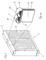
- Fig. 1 shows as an example of a heat exchanger according to the invention a single-row flat tube evaporator 1 with a heat exchanger network 2 and an upper header 3 and a lower header 4.
- this evaporator 1 corresponds to the generic state of the art, ie DE-A 198 26 881 or DE-A-3813339 ,
- the guidance of the refrigerant, ie the flow pattern essentially corresponds to this prior art.
- Fig. 1a shows a section in the region of the collecting tube 3 from the evaporator 1.
- the collecting box 3 is divided by a longitudinal partition wall 5 into two chambers 6a and 6b, in which ends 7, 8 of flat tubes 9 open, which are formed continuously, ie the only row of tubes this Form evaporator 1. Between the flat tubes 9 continuous corrugated fins 10 are arranged, which are flowed over by ambient air.
- the collection box 4, not shown here is constructed analogously.
- Fig. 2 shows a similar section as Fig. 1a ie, an upper header 11 divided into two longitudinal chambers 12, 13.
- a continuous flat tube 14 is formed as an extruded tube and has a plurality of channels 14 'on.
- a separating web 15 is arranged, which divides the flat tube 14 into two flow paths 14a and 14b.
- the separating web 15 terminates in the upper region of the flat tube 14 which opens into the chambers 12, 13 in a recess 16 into which a longitudinal dividing wall 17 of the collecting box 11 engages.
- the flat tube 14 thus has on both sides of the recess 16 two flat tube ends 18, 19, which communicate with the flow paths 14b and 14a.
- Fig. 2a shows a section Fig. 2 in the region of the longitudinal dividing wall 17, which is formed from two adjacent sheet metal sections 17a, 17b of the collecting tank 11.
- the lower end 17 c of the partition wall 17 rests on a bottom 20, which is part of the collecting box 11. From the bottom 20 passages 21 are formed, which receive the pipe ends 18, 19 and are interrupted in the region of the longitudinal partition wall 17.
- Fig. 2b shows a section BB (see. Fig. 2c ) in the plane of the longitudinal dividing wall 17 and the separating webs 15. It can be seen that the upper edge 15a of the separating web 15 abuts against the underside 20a of the bottom 20; the bottom 20 is thus clamped between the upper edge 15a of the separating webs 15 and the lower edge 17c of the longitudinal dividing wall 17. All contact points solder together and thus ensure a secure seal between the two chambers 12, 13 and the flow paths 14a, 14b.
- Fig. 2c shows a further illustration, namely a section along the plane AA (see. Fig. 2b It can be seen that the split flat tube ends 18, 19 are received in passages 21 which are interrupted due to the longitudinal dividing wall 17.
- Fig. 2d shows a part of the longitudinal partition wall 17 with a tab 22, the - as well as in Fig. 2b recognizable - plugged to caulk the header box in a corresponding slot in the ground and is soldered to this tight. Otherwise, the lower edge 17 c of the partition wall 17 is straight, ie adapted to the contour of the bottom 20.
- FIG. 3 shows a second embodiment relevant to the invention.
- a flat tube 23 is divided by a dividing web 24 in the middle, the end 24a of the dividing web 24 lying flush with the upper edge 23a of the flat tubes - the flat tube 23 has, in contrast to the flat tube 14 Fig. 2 so no recess on.
- a longitudinal partition 25 extends.
- Fig. 3a shows a section Fig. 3 in the region of the longitudinal dividing wall 25, which rests on the one hand with its lower edge 25c on a bottom 26 and on the other hand has recesses 27 in the region of the continuous flat tubes 23.
- the recesses 27 in the partition are clearly in Fig. 3d to recognize - they are adapted in shape to the contour of the continuous passages 28 and the flat tubes 23, which are slightly above the upper edge of the passages 27 addition. Due to the continuous passages 28 results in a good soldering of the ends of the flat tubes 23 with the bottom 26.
- the partition 25 is also soldered with its entire lower contour, as in Fig. 3d can be seen, with the bottom 26, the passages 28 and the upper edge 24 a of the separating web 24th
- Fig. 3b shows a section BB in the plane of the partition 25 (corresponding to the plane BB in Fig. 3c ). This results in a dense foreclosure of the two chambers on both sides of the partition 25th
- Fig. 3d shows between the two recesses 27 a tab 29, which, as in Fig. 3b recognizable - engages the bottom 26 and soldered there.
- Fig. 4 shows an embodiment of the invention with a continuous flat tube 30, which in turn is divided in the middle by a divider 31 in two flow paths.
- the flat tube 30 terminates in the two chambers 32, 33 of the collecting tank 34 with the longitudinal partition 35, the - Fig. 4a shows - rests on a bottom 36 of the collecting box 34.
- Fig. 4c shows that this separation web 31 (narrow center web) has a relatively small thickness compared to the thickness of the flat tube 30.
- the ends of the flat tubes 30 are received in non-continuous passages 37, which are interrupted in the region of the partition wall 35.
- the partition wall 35 has - as in Fig. 4d clearly recognizable - from its lower edge 35a outgoing slots 38, which correspond to the contour of the narrow central webs 31 and these include (see. Fig. 4b ).
- the ends of the narrow central webs 31 thus project slightly beyond the bottom 36 and therefore engage in the slots 38 of the partition 35.
- the partition 35 further comprises (see. Fig. 4d ) projecting from its lower edge 35a tabs 39 which engage in the bottom 36 (see. Fig. 4b ).
- connections, not shown, between the lower header 4 and the lower end of the flat tubes 14, 23, 30 are preferably analogous to the embodiments described above.
- the invention has been described with reference to embodiments in which the collecting boxes are each made of a one-piece sheet, which is formed such that two of its longitudinal sides form the longitudinal partition wall of the collecting tank.
- This embodiment is in the DE-A 198 26 881 described. If the collecting tank is placed in its entirety on the flat tube ends during the manufacture of the heat exchanger, the advantages of the invention are particularly borne, in particular the stop for the tube ends in the collecting box, since the tubes are thereby fixable in their position.
- the invention also includes other embodiments, such as heat exchangers with two-piece, ie consisting of tube sheet and lid headers.
Description
- Die Erfindung bezieht sich auf einen Wärmeübertrager, insbesondere einen Verdampfer, bestehend aus einem Wärmeübertragernetz von Wellrippen und Flachrohren, nach dem Oberbegriff des Patentanspruches 1 - bekannt durch die
DE-A-3813339 . - Der durch die
DE-A 198 26 881 bekannt gewordene gelötete Flachrohrverdampfer ist zweireihig ausgebildet, d. h., in Luftströmungsrichtung gesehen, befinden sich zwei Reihen von Flachrohren, zwischen denen Wellrippen angeordnet sind, hintereinander, wobei die Enden der Flachrohre in Sammelkästen münden, die jeweils durch eine Längstrennwand in eine vordere und eine hintere Kammer unterteilt sind. Innerhalb dieser Kammern sind teilweise Quertrennwände vorgesehen. Die Strömung des Kältemittels verläuft in den Flachrohrreihen sowohl von oben nach unten als auch von unten nach oben, wobei eine Umlenkung des Kältemittels einerseits "in der Breite", d. h. quer zur Luftströmungsrichtung und andererseits "in der Tiefe", d. h. in Luftströmungsrichtung erfolgt. Letzteres geschieht durch Überströmöffnungen in der Längstrennwand. Die Herstellung eines solchen Verdampfers wirft, insbesondere beim so genannten Kassettieren, d. h. dem Aufbau des Wärmeübertragernetzes aus Wellrippen und Flachrohren gewisse Probleme auf. Beide Flachrohrreihen müssen genau ausgerichtet werden, damit ihre Enden beim Aufsetzen der Sammelkästen genau in deren Öffnungen passen. Darüber hinaus müssen die Wellrippen zwischen den Flachrohren ebenfalls ausgerichtet werden. Schließlich kann es beim Aufsetzen der Böden auf die Rohrenden zu unterschiedlichen Einstecktiefen der Rohrenden kommen, weil weder an den Flachrohren noch an den Sammelkästen entsprechende Anschläge oder dergleichen vorgesehen sind. Im Hinblick auf die Wärmeübertragungsleistung ergeben sich insofern Potenziale, als die gesamte Tiefe (in Luftströmungsrichtung) dieses Verdampfers nicht in vollem Umfang für die Wärmeübertragung genutzt ist, weil sich zwischen beiden Rohrreihen ein Luftspalt befindet. - Aufgabe der vorliegenden Erfindung ist es daher, einen Wärmeübertrager der eingangs genannten Art dahingehend zu verbessern, dass seine Herstellung vereinfacht wird und damit die Produktionskosten gesenkt sowie seine Leistung verbessert werden.
- Die Lösung dieser Aufgabe ergibt sich aus den Merkmalen des Patentanspruches 1. Danach ist der erfindungsgemäße Wärmeübertrager einreihig ausgebildet, d. h. die Flachrohre sind über die Tiefe (in Luftströmungsrichtung) durchgehend ausgebildet und mit einem in Längsrichtung verlaufenden Trennsteg versehen, der mit der Längstrennwand verlötet ist. Der erfindungsgemäße einreihige Wärmeübertrager und der zweireihige Wärmeübertrager nach dem Stand der Technik sind somit - im Hinblick auf die Kältemittelführung - funktionell gleich. Aus der erfindungsgemäßen Bauweise ergibt sich der Vorteil, dass die durchgehenden Flachrohre und auch die durchgehenden Wellrippen wesentlich einfacher zu kassettieren sind und dass sich darüber hinaus beim Einstecken der Flachrohre in die Böden ein Anschlag ergibt, der die Einstecktiefe der Flachrohrenden definiert. Schließlich wird auch die Wärmeübertragungsleistung gesteigert, weil eine Wärmeübertragung über die gesamte Tiefe des Wärmeübertragers erfolgt.
- Durch die
FR-A 2 803 377 - Vorteilhafte Ausgestaltungen der Erfindung gemäß Anspruch 1 ergeben sich aus den Unteransprüchen.
- In der Erfindung weist das Ende des Flachrohres im Bereich des Trennsteges eine Aussparung auf, mit der es sich gegenüber der Unterseite des Bodens abstützt. Andererseits greift von oben die Längstrennwand in diese Aussparung ein und gewährleistet somit eine dichte Verlötung. Durch die Aussparung wird das Flachrohrende in zwei Flachrohrenden geteilt, die von Durchzügen des Bodens aufgenommen werden, wobei diese Durchzüge im Bereich der längs verlaufenden Trennwand unterbrochen sind.
- In der Erfindung ist das Flachrohrende gerade, d. h. ohne eine Aussparung und wird von einem durchgehenden Durchzug in den Böden der Sammelkästen aufgenommen. Dies ergibt eine gute Verlötung der Flachrohre in den Böden. Die Längstrennwand weist dagegen im Bereich der Durchzüge und der in den Durchzügen angeordneten Flachrohre Aussparungen auf, die an die Kontur von Durchzug und Flachrohr angepasst sind und somit eine gute Verlötung gewährleisten. Bei den zuvor erwähnten Lösungen weist das Flachrohr eine gleich bleibende Dicke auf.
- Gemäss der Erfindung weist das Flachrohr im Bereich des Trennsteges eine geringere Dicke auf, und zwar in Form eines schmalen Mittelsteges, der die beiden Flachrohrhälften verbindet. Das Flachrohrende ist ebenfalls gerade, d. h. ohne Aussparung und durch eine Öffnung im Boden gesteckt, die der Kontur des Flachrohrendes entspricht. Die Längstrennwand weist im Bereich der in den Sammelkasten hineinragenden schmalen Mittelstege schmale Schlitze oder Aussparungen auf, welche die Mittelstege übergreifen - dadurch ist in diesem Bereich eine dichte Verlötung zwischen Längstrennwand und Trennsteg gewährleistet. Vorteilhafterweise sind die. Öffnungen im Boden teilweise als Durchzüge, d. h. im Bereich der Längstrennwand unterbrochene Durchzüge ausgebildet.
- Ausführungsbeispiele der Erfindung sind in der Zeichnung dargestellt und werden im Folgenden näher beschrieben. Es zeigen
- Fig. 1
- einen einreihigen Flachrohrverdampfer ,
- Fig. 1a
- einen Ausschnitt des Flachrohrverdampfers gemäß
Fig. 1 , - Fig. 2, 2a, 2b, 2c, 2d
- eine Ausführungsform relevant für die Erfindung mit Aussparung im Flachrohrende,
- Fig. 3,
- 3a,
- 3b, 3c, 3d
- eine zweite Ausführungsform relevant für die Erfindung mit Aussparung in der Längstrennwand und
- Fig. 4, 4a, 4b, 4c, 4d
- eine Ausführungsform der Erfindung mit schmalem Mittel- steg.
-
Fig. 1 zeigt als Beispiel für einen erfindungsgemäßen Wärmeübertrager einen einreihigen Flachrohrverdampfer 1 mit einem Wärmeübertragernetz 2 und einem oberen Sammelkasten 3 sowie einem unteren Sammelkasten 4. Hinsichtlich der hier nicht dargestellten Kältemittelanschlüsse entspricht dieser Verdampfer 1 dem gattungsgemäßen Stand der Technik, d. h. derDE-A 198 26 881 oderDE-A-3813339 . Auch die Führung des Kältemittels, d. h. das Strömungsmuster entspricht im Wesentlichen diesem Stand der Technik. -
Fig. 1a zeigt einen Ausschnitt im Bereich des Sammelrohres 3 aus dem Verdampfer 1. Der Sammelkasten 3 ist durch eine Längstrennwand 5 in zwei Kammern 6a und 6b unterteilt, in welche Enden 7, 8 von Flachrohren 9 münden, die durchgehend ausgebildet sind, d. h. die einzige Rohrreihe dieses Verdampfers 1 bilden. Zwischen den Flachrohren 9 sind durchgehende Wellrippen 10 angeordnet, die von Umgebungsluft überströmt werden. Der hier nicht dargestellte Sammelkasten 4 ist analog aufgebaut. -
Fig. 2 sowie dieFig. 2a bis 2d zeigen ein Ausführungsbeispiel relevant für die Erfindung.Fig. 2 zeigt einen ähnlichen Ausschnitt wieFig. 1a , d. h. einen oberen Sammelkasten 11, der in zwei in Längsrichtung verlaufenden Kammern 12, 13 unterteilt ist. Ein durchgehendes Flachrohr 14 ist als extrudiertes Rohr ausgebildet und weist eine Vielzahl von Kanälen 14' auf. Mittig und in Längsrichtung des Flachrohres 14 verlaufend, ist ein Trennsteg 15 angeordnet, der das Flachrohr 14 in zwei Strömungswege 14a und 14b unterteilt. Der Trennsteg 15 endet im oberen in die Kammern 12, 13 mündenden Bereich des Flachrohres 14 in einer Aussparung 16, in welche eine Längstrennwand 17 des Sammelkastens 11 eingreift. Das Flachrohr 14 weist somit beiderseits der Aussparung 16 zwei Flachrohrenden 18, 19 auf, die mit den Strömungswegen 14b bzw. 14 a kommunizieren. -
Fig. 2a zeigt einen Ausschnitt ausFig. 2 im Bereich der Längstrennwand 17, die aus zwei aneinander liegenden Blechabschnitten 17a, 17b des Sammelkastens 11 gebildet ist. Das untere Ende 17c der Trennwand 17 liegt auf einem Boden 20 auf, der Teil des Sammelkasten 11 ist. Aus dem Boden 20 sind Durchzüge 21 ausgeformt, welche die Rohrenden 18, 19 aufnehmen und im Bereich der Längstrennwand 17 unterbrochen sind. -
Fig. 2b zeigt einen Schnitt B-B (vgl.Fig. 2c ) in der Ebene der Längstrennwand 17 und der Trennstege 15. Man sieht, dass die Oberkante 15a des Trennsteges 15 an die Unterseite 20a des Bodens 20 anstößt; der Boden 20 ist somit zwischen Oberkante 15a der Trennstege 15 und Unterkante 17c der Längstrennwand 17 eingespannt. Alle Kontaktstellen verlöten miteinander und gewährleisten somit eine sichere Abdichtung zwischen den beiden Kammern 12, 13 und den Strömungswegen 14a, 14b. -
Fig. 2c zeigt eine weitere Darstellung, und zwar einen Schnitt längs der Ebene A-A (vgl.Fig. 2b ), d. h. etwa parallel zum Boden 20 durch die Trennwand 17. Man erkennt, dass die geteilten Flachrohrenden 18, 19 in Durchzügen 21 aufgenommen sind, die aufgrund der Längstrennwand 17 unterbrochen sind. -
Fig. 2d zeigt einen Teil der Längstrennwand 17 mit einem Lappen 22, der - wie auch inFig. 2b erkennbar - zur Verstemmung des Sammelkastens in einen entsprechenden Schlitz im Boden gesteckt und mit diesem dicht verlötet ist. Ansonsten ist die Unterkante 17c der Trennwand 17 durchgehend gerade, d. h. an die Kontur des Bodens 20 angepasst. -
Fig. 3 sowie dieFig. 3a bis 3d zeigen ein zweites Ausführungsbeispiel relevant für die Erfindung. Ein Flachrohr 23 ist durch einen Trennsteg 24 in der Mitte geteilt, wobei das Ende 24a des Trennsteges 24 mit der Oberkante 23a der Flachrohre auf einer Höhe liegt - das Flachrohr 23 weist im Gegensatz zu dem Flachrohr 14 ausFig. 2 also keine Aussparung auf. In Verlängerung des Steges 24 erstreckt sich eine Längstrennwand 25. -
Fig. 3a zeigt einen Ausschnitt ausFig. 3 im Bereich der Längstrennwand 25, die einerseits mit ihrer Unterkante 25c auf einem Boden 26 aufliegt und andererseits Aussparungen 27 im Bereich der durchgehenden Flachrohre 23 aufweist. Aus dem Boden 26 sind durchgehende Durchzüge 28 ausgeformt, was besonders deutlich aus der Draufsicht inFig. 3c hervorgeht. Die Aussparungen 27 in der Trennwand sind deutlich inFig. 3d zu erkennen - sie sind in ihrer Form der Kontur der durchgehenden Durchzüge 28 und der Flachrohre 23 angepasst, die etwas über die Oberkante der Durchzüge 27 hinaus stehen. Aufgrund der durchgehenden Durchzüge 28 ergibt sich eine gute Verlötung der Enden der Flachrohre 23 mit dem Boden 26. Die Trennwand 25 verlötet ebenfalls mit ihrer gesamten unteren Kontur, wie sie inFig. 3d erkennbar ist, mit dem Boden 26, den Durchzügen 28 und der Oberkante 24a des Trennsteges 24. -
Fig. 3b zeigt einen Schnitt B-B in der Ebene der Trennwand 25 (entsprechend der Ebene B-B inFig. 3c ). Es ergibt sich somit eine dichte Abschottung der beiden Kammern beiderseits der Trennwand 25. -
Fig. 3d zeigt zwischen den beiden Aussparungen 27 einen Lappen 29, der, wie auch inFig. 3b erkennbar - in den Boden 26 eingreift und dort verlötet ist. -
Fig. 4 zeigt ein Ausführungsbeispiel der Erfindung mit einem durchgehenden Flachrohr 30, welches wiederum in der Mitte durch einen Trennsteg 31 in zwei Strömungswege unterteilt ist. Das Flachrohr 30 mündet endseitig in die beiden Kammern 32, 33 des Sammelkastens 34 mit der Längstrennwand 35, die - wieFig. 4a zeigt - auf einem Boden 36 des Sammelkasten 34 aufliegt. -
Fig. 4c zeigt, dass dieser Trennsteg 31 (schmaler Mittelsteg) eine relativ geringe Dicke gegenüber der Dicke des Flachrohres 30 aufweist. Die Enden der Flachrohre 30 sind in nicht durchgehenden Durchzügen 37 aufgenommen, die im Bereich der Trennwand 35 unterbrochen sind. Die Trennwand 35 weist - wie inFig. 4d deutlich erkennbar - von ihrer Unterkante 35a ausgehende Schlitze 38 auf, welche der Kontur der schmalen Mittelstege 31 entsprechen und diese umfassen (vgl.Fig. 4b ). Die Enden der schmalen Mittelstege 31 ragen also etwas über den Boden 36 hinaus und greifen daher in die Schlitze 38 der Trennwand 35 ein. Somit ist auch hier eine sichere Verlötung zwischen Trennwand 35 und Trennsteg 31 gewährleistet. Die Trennwand 35 weist ferner (vgl.Fig. 4d ) von ihrer Unterkante 35a abragende Lappen 39 auf, die in den Boden 36 eingreifen (vgl.Fig. 4b ). - Die nicht dargestellten Verbindungen zwischen dem unteren Sammelkasten 4 und dem unteren Ende der Flachrohre 14, 23, 30 sind vorzugsweise analog zu den oben beschriebenen Ausführungsbeispielen.
- Die Erfindung wurde anhand von Ausführungsbeispielen beschrieben, bei denen die Sammelkästen jeweils aus einem einteiligen Blech hergestellt sind, das derart umgeformt wird, daß zwei seiner Längsseiten die Längstrennwand des Sammelkastens bilden. Diese Ausgestaltung ist in der
DE-A 198 26 881 beschrieben. Wird der Sammelkasten während der Fertigung des Wärmeübertragers in seiner Gesamtheit auf die Flachrohrenden aufgesetzt, kommen die Vorteile der Erfindung besonders zu tragen, insbesondere der Anschlag für die Rohrenden in dem Sammelkasten, da die Rohre hierdurch in ihrer Lage fixierbar sind. - Die Erfindung umfaßt jedoch auch andere Ausgestaltungsformen, wie beispielsweise Wärmeübertrager mit zweiteiligen, das heißt aus Rohrboden und Deckel bestehenden Sammelkästen.
Claims (10)
- Wärmeübertrager, insbesondere Verdampfer, bestehend aus einem Wärmeübertragernetz von Wellrippen und Flachrohren sowie aus mindestens einem durch eine Längstrennwand in Kammern unterteilten Sammelkasten, wobei der Sammelkasten einen Boden mit Öffnungen aufweist, in welchen Enden der Flachrohre aufgenommen sind, wobei die Flachrohre (14, 23, 30) in Luftströmungsrichtung durchgehend ausgebildet und in einer Reihe angeordnet sind und je einen in Längsrichtung verlaufenden, mit den Längstrennwänden (17, 25 35) fluchtenden Trennsteg (15, 24, 31) aufweisen, dadurch gekennzeichnet, das Flachrohr (30) im Bereich des Trennsteges (31) eine geringere Dicke in Form eines schmalen Mittelsteges (31) aufweist und dass die Längstrennwand (35) Aussparungen (38) aufweist, in welche das den Boden (36) überragende Ende des Mittelsteges (31) eingreift.
- Wärmeübertrager nach Anspruch 1, dadurch gekennzeichnet, dass die Breite der Aussparung (16) der Dicke der Trennwand (17) entspricht.
- Wärmeübertrager nach Anspruch 1 oder 2, dadurch gekennzeichnet, dass die Längstrennwand mit dem Trennsteg verlötet ist.
- Wärmeübertrager nach Anspruch 1, 2, dadurch gekennzeichnet, dass die Längstrennwand (17) mittelbar über den Boden (20) mit dem Trennsteg (15) verlötet ist.
- Wärmeübertrager nach Anspruch 1, 2, 3 oder 4, dadurch gekennzeichnet dass die Flachrohre (14) beiderseits der Aussparung (16) Flachrohrenden (18, 19) aufweisen, die von den Öffnungen im Boden (20) aufgenommen werden.
- Wärmeübertrager nach Anspruch 5, dadurch gekennzeichnet, dass die Öffnungen als Durchzüge (21) ausgebildet sind, die im Bereich der Längstrennwand (17) unterbrochen sind.
- Wärmeübertrager nach Anspruch 1, dadurch gekennzeichnet, dass die Öffnungen im Boden (26) als durchgehende Durchzüge (28) ausgebildet sind und dass die Längstrennwand (25) im Bereich der Durchzüge (28) Aussparungen (27) aufweist.
- Wärmeübertrager nach Anspruch 1, dadurch gekennzeichnet, dass die Längstrennwand (25) vereinzelt Lappen (29) aufweist, die durch Schlitze im Boden (26) gesteckt und insbesondere verstemmt sind.
- Wärmeübertrager nach Anspruch 1, dadurch gekennzeichnet, dass die Öffnungen im Boden (36) als unterbrochene Durchzüge (37) ausgebildet sind, die jeweils durch einen Schlitz zur Aufnahme des schmalen Mittelsteges verbunden sind.
- Wärmeübertrager nach einem der vorhergehenden Ansprüche, dadurch gekennzeichnet, dass der Boden und die Längstrennwand des Sammelkastens einstückig ausgebildet sind.
Applications Claiming Priority (3)
| Application Number | Priority Date | Filing Date | Title |
|---|---|---|---|
| DE10243416A DE10243416A1 (de) | 2002-09-18 | 2002-09-18 | Wärmeübertrager, insbesondere Verdampfer |
| DE10243416 | 2002-09-18 | ||
| PCT/EP2003/009930 WO2004029533A1 (de) | 2002-09-18 | 2003-09-08 | Wärmeübertrager, insbesondere verdampfer |
Publications (2)
| Publication Number | Publication Date |
|---|---|
| EP1552238A1 EP1552238A1 (de) | 2005-07-13 |
| EP1552238B1 true EP1552238B1 (de) | 2010-07-07 |
Family
ID=31969240
Family Applications (1)
| Application Number | Title | Priority Date | Filing Date |
|---|---|---|---|
| EP03747979A Expired - Lifetime EP1552238B1 (de) | 2002-09-18 | 2003-09-08 | Wärmeübertrager, insbesondere verdampfer |
Country Status (7)
| Country | Link |
|---|---|
| EP (1) | EP1552238B1 (de) |
| JP (1) | JP4348297B2 (de) |
| CN (1) | CN100390487C (de) |
| AT (1) | ATE473409T1 (de) |
| AU (1) | AU2003267057A1 (de) |
| DE (2) | DE10243416A1 (de) |
| WO (1) | WO2004029533A1 (de) |
Families Citing this family (3)
| Publication number | Priority date | Publication date | Assignee | Title |
|---|---|---|---|---|
| KR100913141B1 (ko) * | 2004-09-15 | 2009-08-19 | 삼성전자주식회사 | 마이크로채널튜브를 이용한 증발기 |
| CN102401602A (zh) * | 2011-11-24 | 2012-04-04 | 无锡市鑫盛换热器制造有限公司 | 一种防热裂型换热器 |
| CN108204635A (zh) * | 2018-01-17 | 2018-06-26 | 珠海格力电器股份有限公司 | 钣金件的连接结构及室外机及空调器 |
Family Cites Families (18)
| Publication number | Priority date | Publication date | Assignee | Title |
|---|---|---|---|---|
| DE3302150A1 (de) * | 1983-01-22 | 1984-07-26 | Thermal-Werke, Wärme-, Kälte-, Klimatechnik GmbH, 6909 Walldorf | Waermetauscher und verfahren zu seiner herstellung |
| DE3813339C2 (de) * | 1988-04-21 | 1997-07-24 | Gea Happel Klimatechnik | Wärmetauscher für Kraftfahrzeuge und Verfahren zu seiner Herstellung |
| US5174373A (en) * | 1990-07-13 | 1992-12-29 | Sanden Corporation | Heat exchanger |
| JPH0566073A (ja) * | 1991-09-05 | 1993-03-19 | Sanden Corp | 積層型熱交換器 |
| US5186244A (en) * | 1992-04-08 | 1993-02-16 | General Motors Corporation | Tube design for integral radiator/condenser |
| EP0656517B1 (de) * | 1993-12-03 | 1999-02-10 | Valeo Klimatechnik GmbH & Co. KG | Wasser/Luft-Wärmetauscher aus Aluminium für Kraftfahrzeuge |
| JPH08254399A (ja) * | 1995-01-19 | 1996-10-01 | Zexel Corp | 熱交換器 |
| FR2755222B1 (fr) * | 1996-10-30 | 1999-01-08 | Valeo Thermique Moteur Sa | Echangeur de chaleur comportant une boite collectrice a deux compartiments adjacents |
| US5904206A (en) * | 1998-02-25 | 1999-05-18 | General Motors Corporation | Heat exchanger flow tube with improved header to tube end stress resistance |
| JPH11337289A (ja) * | 1998-05-27 | 1999-12-10 | Showa Alum Corp | 熱交換器 |
| DE19826881B4 (de) * | 1998-06-17 | 2008-01-03 | Behr Gmbh & Co. Kg | Wärmeübertrager, insbesondere Verdampfer |
| FR2787180B1 (fr) * | 1998-12-11 | 2001-03-02 | Valeo Thermique Moteur Sa | Tube plie pour echangeur de chaleur et procede pour sa conformation |
| DE19920102B4 (de) * | 1999-05-03 | 2009-01-02 | Behr Gmbh & Co. Kg | Mehrkammerrohr und Wärmeübertrageranordnung für ein Kraftfahrzeug |
| DE19933913C2 (de) * | 1999-07-20 | 2003-07-17 | Valeo Klimatechnik Gmbh | Verdampfer einer Kraftfahrzeugklimaanlage |
| CN1163719C (zh) * | 1999-08-20 | 2004-08-25 | 瓦莱奥空调技术有限公司 | 汽车供暖热交换器或发动机冷却器用的换热器 |
| FR2803377B1 (fr) * | 1999-12-29 | 2002-09-06 | Valeo Climatisation | Evaporateur a tubes plats empiles a configuration en u |
| GB2361301B (en) * | 2000-03-16 | 2003-10-08 | Denso Corp | Self clamping groove in a seamed tube |
| JP4254015B2 (ja) * | 2000-05-15 | 2009-04-15 | 株式会社デンソー | 熱交換器 |
-
2002
- 2002-09-18 DE DE10243416A patent/DE10243416A1/de not_active Withdrawn
-
2003
- 2003-09-08 AT AT03747979T patent/ATE473409T1/de not_active IP Right Cessation
- 2003-09-08 WO PCT/EP2003/009930 patent/WO2004029533A1/de active Application Filing
- 2003-09-08 CN CNB038221462A patent/CN100390487C/zh not_active Expired - Fee Related
- 2003-09-08 AU AU2003267057A patent/AU2003267057A1/en not_active Abandoned
- 2003-09-08 EP EP03747979A patent/EP1552238B1/de not_active Expired - Lifetime
- 2003-09-08 DE DE50312864T patent/DE50312864D1/de not_active Expired - Lifetime
- 2003-09-08 JP JP2004538869A patent/JP4348297B2/ja not_active Expired - Fee Related
Also Published As
| Publication number | Publication date |
|---|---|
| ATE473409T1 (de) | 2010-07-15 |
| AU2003267057A1 (en) | 2004-04-19 |
| JP4348297B2 (ja) | 2009-10-21 |
| CN100390487C (zh) | 2008-05-28 |
| EP1552238A1 (de) | 2005-07-13 |
| DE50312864D1 (de) | 2010-08-19 |
| JP2005539197A (ja) | 2005-12-22 |
| CN1682090A (zh) | 2005-10-12 |
| WO2004029533A1 (de) | 2004-04-08 |
| DE10243416A1 (de) | 2004-04-01 |
Similar Documents
| Publication | Publication Date | Title |
|---|---|---|
| DE10056074B4 (de) | Wärmeübertrager | |
| EP2026028B1 (de) | Wärmeübertrager, insbesondere für ein Kraftfahrzeug | |
| DE19719251C2 (de) | Verteil-/Sammel-Kasten eines mindestens zweiflutigen Verdampfers einer Kraftfahrzeugklimaanlage | |
| DE19752139B4 (de) | Wärmeübertrager für ein Kraftfahrzeug | |
| DE19826881B4 (de) | Wärmeübertrager, insbesondere Verdampfer | |
| DE10330268A1 (de) | Wärmeübertrager, insbesondere Verdampfer für eine Fahrzeugklimaanlage | |
| DE102008023055A1 (de) | Wärmeübertrager | |
| EP0929784B1 (de) | Flachrohrwärmetauscher für kraftfahrzeuge mit an krägen eines rohrbodens gehaltenen flachrohren | |
| EP0912869B1 (de) | Mehr als zweiflutiger flachrohrwärmetauscher für kraftfahrzeuge mit umlenkboden sowie herstellungsverfahren | |
| DE4305060C2 (de) | Gelöteter Wärmetauscher, insbesondere Verdampfer | |
| EP2962056A1 (de) | Wärmeübertrager | |
| DE4305945A1 (de) | Wärmetauscher, insbesondere für Kraftfahrzeuge | |
| EP1601915B1 (de) | Vorrichtung zum wärmeübertragung | |
| DE69711351T9 (de) | Endkammer in zwei Teilen für Wärmetauscher | |
| DE4330214B4 (de) | Wärmetauscher | |
| EP1934545B1 (de) | Heizkörper, kühlkreislauf, klimagerät für eine kraftfahrzeug-klimaanlage sowie klimaanlage für ein kraftfahrzeug | |
| EP1552238B1 (de) | Wärmeübertrager, insbesondere verdampfer | |
| DE19858325B4 (de) | Wärmeübertrageranordnung für ein Kraftfahrzeug | |
| DE60201538T2 (de) | Wärmetauscher mit verbesserter leistung, insbesondere verdampfer | |
| EP0910778A1 (de) | Flachrohrverdampfer mit vertikaler längserstreckungsrichtung der flachrohre bei kraftfahrzeugen | |
| DE10132484A1 (de) | Wärmetauscher und Verfahren zu dessen Herstellung | |
| DE60201554T2 (de) | Verdampfer mit hoher Kälteleistung für Kraftfahrzeugklimaanlage | |
| DE10231918A1 (de) | Verdampfer für Kfz-Klimaanlagen |
Legal Events
| Date | Code | Title | Description |
|---|---|---|---|
| PUAI | Public reference made under article 153(3) epc to a published international application that has entered the european phase |
Free format text: ORIGINAL CODE: 0009012 |
|
| 17P | Request for examination filed |
Effective date: 20050418 |
|
| AK | Designated contracting states |
Kind code of ref document: A1 Designated state(s): AT BE BG CH CY CZ DE DK EE ES FI FR GB GR HU IE IT LI LU MC NL PT RO SE SI SK TR |
|
| AX | Request for extension of the european patent |
Extension state: AL LT LV MK |
|
| DAX | Request for extension of the european patent (deleted) | ||
| RAP1 | Party data changed (applicant data changed or rights of an application transferred) |
Owner name: BEHR GMBH & CO. KG |
|
| 17Q | First examination report despatched |
Effective date: 20090326 |
|
| GRAP | Despatch of communication of intention to grant a patent |
Free format text: ORIGINAL CODE: EPIDOSNIGR1 |
|
| GRAS | Grant fee paid |
Free format text: ORIGINAL CODE: EPIDOSNIGR3 |
|
| GRAA | (expected) grant |
Free format text: ORIGINAL CODE: 0009210 |
|
| AK | Designated contracting states |
Kind code of ref document: B1 Designated state(s): AT BE BG CH CY CZ DE DK EE ES FI FR GB GR HU IE IT LI LU MC NL PT RO SE SI SK TR |
|
| REG | Reference to a national code |
Ref country code: GB Ref legal event code: FG4D Free format text: NOT ENGLISH |
|
| REG | Reference to a national code |
Ref country code: CH Ref legal event code: EP |
|
| REG | Reference to a national code |
Ref country code: IE Ref legal event code: FG4D |
|
| REF | Corresponds to: |
Ref document number: 50312864 Country of ref document: DE Date of ref document: 20100819 Kind code of ref document: P |
|
| REG | Reference to a national code |
Ref country code: NL Ref legal event code: VDEP Effective date: 20100707 |
|
| PG25 | Lapsed in a contracting state [announced via postgrant information from national office to epo] |
Ref country code: SI Free format text: LAPSE BECAUSE OF FAILURE TO SUBMIT A TRANSLATION OF THE DESCRIPTION OR TO PAY THE FEE WITHIN THE PRESCRIBED TIME-LIMIT Effective date: 20100707 |
|
| PG25 | Lapsed in a contracting state [announced via postgrant information from national office to epo] |
Ref country code: NL Free format text: LAPSE BECAUSE OF FAILURE TO SUBMIT A TRANSLATION OF THE DESCRIPTION OR TO PAY THE FEE WITHIN THE PRESCRIBED TIME-LIMIT Effective date: 20100707 Ref country code: FI Free format text: LAPSE BECAUSE OF FAILURE TO SUBMIT A TRANSLATION OF THE DESCRIPTION OR TO PAY THE FEE WITHIN THE PRESCRIBED TIME-LIMIT Effective date: 20100707 |
|
| REG | Reference to a national code |
Ref country code: IE Ref legal event code: FD4D |
|
| PG25 | Lapsed in a contracting state [announced via postgrant information from national office to epo] |
Ref country code: BG Free format text: LAPSE BECAUSE OF FAILURE TO SUBMIT A TRANSLATION OF THE DESCRIPTION OR TO PAY THE FEE WITHIN THE PRESCRIBED TIME-LIMIT Effective date: 20101007 Ref country code: PT Free format text: LAPSE BECAUSE OF FAILURE TO SUBMIT A TRANSLATION OF THE DESCRIPTION OR TO PAY THE FEE WITHIN THE PRESCRIBED TIME-LIMIT Effective date: 20101108 Ref country code: CY Free format text: LAPSE BECAUSE OF FAILURE TO SUBMIT A TRANSLATION OF THE DESCRIPTION OR TO PAY THE FEE WITHIN THE PRESCRIBED TIME-LIMIT Effective date: 20100707 |
|
| PGFP | Annual fee paid to national office [announced via postgrant information from national office to epo] |
Ref country code: CZ Payment date: 20100908 Year of fee payment: 8 |
|
| BERE | Be: lapsed |
Owner name: BEHR G.M.B.H. & CO. KG Effective date: 20100930 |
|
| PG25 | Lapsed in a contracting state [announced via postgrant information from national office to epo] |
Ref country code: GR Free format text: LAPSE BECAUSE OF FAILURE TO SUBMIT A TRANSLATION OF THE DESCRIPTION OR TO PAY THE FEE WITHIN THE PRESCRIBED TIME-LIMIT Effective date: 20101008 Ref country code: SE Free format text: LAPSE BECAUSE OF FAILURE TO SUBMIT A TRANSLATION OF THE DESCRIPTION OR TO PAY THE FEE WITHIN THE PRESCRIBED TIME-LIMIT Effective date: 20100707 |
|
| PG25 | Lapsed in a contracting state [announced via postgrant information from national office to epo] |
Ref country code: DK Free format text: LAPSE BECAUSE OF FAILURE TO SUBMIT A TRANSLATION OF THE DESCRIPTION OR TO PAY THE FEE WITHIN THE PRESCRIBED TIME-LIMIT Effective date: 20100707 Ref country code: MC Free format text: LAPSE BECAUSE OF NON-PAYMENT OF DUE FEES Effective date: 20100930 Ref country code: IE Free format text: LAPSE BECAUSE OF FAILURE TO SUBMIT A TRANSLATION OF THE DESCRIPTION OR TO PAY THE FEE WITHIN THE PRESCRIBED TIME-LIMIT Effective date: 20100707 |
|
| REG | Reference to a national code |
Ref country code: CH Ref legal event code: PL |
|
| PLBE | No opposition filed within time limit |
Free format text: ORIGINAL CODE: 0009261 |
|
| STAA | Information on the status of an ep patent application or granted ep patent |
Free format text: STATUS: NO OPPOSITION FILED WITHIN TIME LIMIT |
|
| PG25 | Lapsed in a contracting state [announced via postgrant information from national office to epo] |
Ref country code: IT Free format text: LAPSE BECAUSE OF FAILURE TO SUBMIT A TRANSLATION OF THE DESCRIPTION OR TO PAY THE FEE WITHIN THE PRESCRIBED TIME-LIMIT Effective date: 20100707 Ref country code: EE Free format text: LAPSE BECAUSE OF FAILURE TO SUBMIT A TRANSLATION OF THE DESCRIPTION OR TO PAY THE FEE WITHIN THE PRESCRIBED TIME-LIMIT Effective date: 20100707 Ref country code: RO Free format text: LAPSE BECAUSE OF FAILURE TO SUBMIT A TRANSLATION OF THE DESCRIPTION OR TO PAY THE FEE WITHIN THE PRESCRIBED TIME-LIMIT Effective date: 20100707 Ref country code: SK Free format text: LAPSE BECAUSE OF FAILURE TO SUBMIT A TRANSLATION OF THE DESCRIPTION OR TO PAY THE FEE WITHIN THE PRESCRIBED TIME-LIMIT Effective date: 20100707 |
|
| 26N | No opposition filed |
Effective date: 20110408 |
|
| GBPC | Gb: european patent ceased through non-payment of renewal fee |
Effective date: 20101007 |
|
| PG25 | Lapsed in a contracting state [announced via postgrant information from national office to epo] |
Ref country code: ES Free format text: LAPSE BECAUSE OF FAILURE TO SUBMIT A TRANSLATION OF THE DESCRIPTION OR TO PAY THE FEE WITHIN THE PRESCRIBED TIME-LIMIT Effective date: 20101018 |
|
| REG | Reference to a national code |
Ref country code: DE Ref legal event code: R097 Ref document number: 50312864 Country of ref document: DE Effective date: 20110408 |
|
| PG25 | Lapsed in a contracting state [announced via postgrant information from national office to epo] |
Ref country code: BE Free format text: LAPSE BECAUSE OF NON-PAYMENT OF DUE FEES Effective date: 20100930 Ref country code: CH Free format text: LAPSE BECAUSE OF NON-PAYMENT OF DUE FEES Effective date: 20100930 Ref country code: LI Free format text: LAPSE BECAUSE OF NON-PAYMENT OF DUE FEES Effective date: 20100930 |
|
| PG25 | Lapsed in a contracting state [announced via postgrant information from national office to epo] |
Ref country code: GB Free format text: LAPSE BECAUSE OF NON-PAYMENT OF DUE FEES Effective date: 20101007 |
|
| PG25 | Lapsed in a contracting state [announced via postgrant information from national office to epo] |
Ref country code: AT Free format text: LAPSE BECAUSE OF NON-PAYMENT OF DUE FEES Effective date: 20100908 |
|
| PGFP | Annual fee paid to national office [announced via postgrant information from national office to epo] |
Ref country code: FR Payment date: 20110927 Year of fee payment: 9 |
|
| PG25 | Lapsed in a contracting state [announced via postgrant information from national office to epo] |
Ref country code: CZ Free format text: LAPSE BECAUSE OF NON-PAYMENT OF DUE FEES Effective date: 20110908 |
|
| PG25 | Lapsed in a contracting state [announced via postgrant information from national office to epo] |
Ref country code: HU Free format text: LAPSE BECAUSE OF FAILURE TO SUBMIT A TRANSLATION OF THE DESCRIPTION OR TO PAY THE FEE WITHIN THE PRESCRIBED TIME-LIMIT Effective date: 20110108 Ref country code: LU Free format text: LAPSE BECAUSE OF NON-PAYMENT OF DUE FEES Effective date: 20100908 |
|
| PG25 | Lapsed in a contracting state [announced via postgrant information from national office to epo] |
Ref country code: TR Free format text: LAPSE BECAUSE OF FAILURE TO SUBMIT A TRANSLATION OF THE DESCRIPTION OR TO PAY THE FEE WITHIN THE PRESCRIBED TIME-LIMIT Effective date: 20100707 |
|
| REG | Reference to a national code |
Ref country code: FR Ref legal event code: ST Effective date: 20130531 |
|
| PG25 | Lapsed in a contracting state [announced via postgrant information from national office to epo] |
Ref country code: FR Free format text: LAPSE BECAUSE OF NON-PAYMENT OF DUE FEES Effective date: 20121001 |
|
| REG | Reference to a national code |
Ref country code: DE Ref legal event code: R082 Ref document number: 50312864 Country of ref document: DE Representative=s name: GRAUEL, ANDREAS, DIPL.-PHYS. DR. RER. NAT., DE |
|
| REG | Reference to a national code |
Ref country code: DE Ref legal event code: R082 Ref document number: 50312864 Country of ref document: DE Representative=s name: GRAUEL, ANDREAS, DIPL.-PHYS. DR. RER. NAT., DE Effective date: 20150227 Ref country code: DE Ref legal event code: R081 Ref document number: 50312864 Country of ref document: DE Owner name: MAHLE INTERNATIONAL GMBH, DE Free format text: FORMER OWNER: BEHR GMBH & CO. KG, 70469 STUTTGART, DE Effective date: 20150227 |
|
| PGFP | Annual fee paid to national office [announced via postgrant information from national office to epo] |
Ref country code: DE Payment date: 20181001 Year of fee payment: 16 |
|
| REG | Reference to a national code |
Ref country code: DE Ref legal event code: R119 Ref document number: 50312864 Country of ref document: DE |
|
| PG25 | Lapsed in a contracting state [announced via postgrant information from national office to epo] |
Ref country code: DE Free format text: LAPSE BECAUSE OF NON-PAYMENT OF DUE FEES Effective date: 20200401 |