EP1550811B1 - Lüfter für Kühlschränke - Google Patents
Lüfter für Kühlschränke Download PDFInfo
- Publication number
- EP1550811B1 EP1550811B1 EP04028478.8A EP04028478A EP1550811B1 EP 1550811 B1 EP1550811 B1 EP 1550811B1 EP 04028478 A EP04028478 A EP 04028478A EP 1550811 B1 EP1550811 B1 EP 1550811B1
- Authority
- EP
- European Patent Office
- Prior art keywords
- cool air
- centrifugal fan
- blades
- introduction hole
- fan
- Prior art date
- Legal status (The legal status is an assumption and is not a legal conclusion. Google has not performed a legal analysis and makes no representation as to the accuracy of the status listed.)
- Expired - Lifetime
Links
Images


Classifications
-
- F—MECHANICAL ENGINEERING; LIGHTING; HEATING; WEAPONS; BLASTING
- F25—REFRIGERATION OR COOLING; COMBINED HEATING AND REFRIGERATION SYSTEMS; HEAT PUMP SYSTEMS; MANUFACTURE OR STORAGE OF ICE; LIQUEFACTION SOLIDIFICATION OF GASES
- F25D—REFRIGERATORS; COLD ROOMS; ICE-BOXES; COOLING OR FREEZING APPARATUS NOT OTHERWISE PROVIDED FOR
- F25D17/00—Arrangements for circulating cooling fluids; Arrangements for circulating gas, e.g. air, within refrigerated spaces
- F25D17/04—Arrangements for circulating cooling fluids; Arrangements for circulating gas, e.g. air, within refrigerated spaces for circulating air, e.g. by convection
- F25D17/06—Arrangements for circulating cooling fluids; Arrangements for circulating gas, e.g. air, within refrigerated spaces for circulating air, e.g. by convection by forced circulation
-
- F—MECHANICAL ENGINEERING; LIGHTING; HEATING; WEAPONS; BLASTING
- F04—POSITIVE - DISPLACEMENT MACHINES FOR LIQUIDS; PUMPS FOR LIQUIDS OR ELASTIC FLUIDS
- F04D—NON-POSITIVE-DISPLACEMENT PUMPS
- F04D29/00—Details, component parts, or accessories
- F04D29/26—Rotors specially for elastic fluids
- F04D29/28—Rotors specially for elastic fluids for centrifugal or helico-centrifugal pumps for radial-flow or helico-centrifugal pumps
- F04D29/281—Rotors specially for elastic fluids for centrifugal or helico-centrifugal pumps for radial-flow or helico-centrifugal pumps for fans or blowers
- F04D29/282—Rotors specially for elastic fluids for centrifugal or helico-centrifugal pumps for radial-flow or helico-centrifugal pumps for fans or blowers the leading edge of each vane being substantially parallel to the rotation axis
-
- F—MECHANICAL ENGINEERING; LIGHTING; HEATING; WEAPONS; BLASTING
- F04—POSITIVE - DISPLACEMENT MACHINES FOR LIQUIDS; PUMPS FOR LIQUIDS OR ELASTIC FLUIDS
- F04D—NON-POSITIVE-DISPLACEMENT PUMPS
- F04D29/00—Details, component parts, or accessories
- F04D29/40—Casings; Connections of working fluid
- F04D29/42—Casings; Connections of working fluid for radial or helico-centrifugal pumps
- F04D29/4206—Casings; Connections of working fluid for radial or helico-centrifugal pumps especially adapted for elastic fluid pumps
- F04D29/4213—Casings; Connections of working fluid for radial or helico-centrifugal pumps especially adapted for elastic fluid pumps suction ports
-
- F—MECHANICAL ENGINEERING; LIGHTING; HEATING; WEAPONS; BLASTING
- F25—REFRIGERATION OR COOLING; COMBINED HEATING AND REFRIGERATION SYSTEMS; HEAT PUMP SYSTEMS; MANUFACTURE OR STORAGE OF ICE; LIQUEFACTION SOLIDIFICATION OF GASES
- F25D—REFRIGERATORS; COLD ROOMS; ICE-BOXES; COOLING OR FREEZING APPARATUS NOT OTHERWISE PROVIDED FOR
- F25D17/00—Arrangements for circulating cooling fluids; Arrangements for circulating gas, e.g. air, within refrigerated spaces
- F25D17/04—Arrangements for circulating cooling fluids; Arrangements for circulating gas, e.g. air, within refrigerated spaces for circulating air, e.g. by convection
- F25D17/06—Arrangements for circulating cooling fluids; Arrangements for circulating gas, e.g. air, within refrigerated spaces for circulating air, e.g. by convection by forced circulation
- F25D17/067—Evaporator fan units
-
- F—MECHANICAL ENGINEERING; LIGHTING; HEATING; WEAPONS; BLASTING
- F25—REFRIGERATION OR COOLING; COMBINED HEATING AND REFRIGERATION SYSTEMS; HEAT PUMP SYSTEMS; MANUFACTURE OR STORAGE OF ICE; LIQUEFACTION SOLIDIFICATION OF GASES
- F25D—REFRIGERATORS; COLD ROOMS; ICE-BOXES; COOLING OR FREEZING APPARATUS NOT OTHERWISE PROVIDED FOR
- F25D2317/00—Details or arrangements for circulating cooling fluids; Details or arrangements for circulating gas, e.g. air, within refrigerated spaces, not provided for in other groups of this subclass
- F25D2317/06—Details or arrangements for circulating cooling fluids; Details or arrangements for circulating gas, e.g. air, within refrigerated spaces, not provided for in other groups of this subclass with forced air circulation
- F25D2317/068—Details or arrangements for circulating cooling fluids; Details or arrangements for circulating gas, e.g. air, within refrigerated spaces, not provided for in other groups of this subclass with forced air circulation characterised by the fans
- F25D2317/0681—Details thereof
-
- F—MECHANICAL ENGINEERING; LIGHTING; HEATING; WEAPONS; BLASTING
- F25—REFRIGERATION OR COOLING; COMBINED HEATING AND REFRIGERATION SYSTEMS; HEAT PUMP SYSTEMS; MANUFACTURE OR STORAGE OF ICE; LIQUEFACTION SOLIDIFICATION OF GASES
- F25D—REFRIGERATORS; COLD ROOMS; ICE-BOXES; COOLING OR FREEZING APPARATUS NOT OTHERWISE PROVIDED FOR
- F25D2317/00—Details or arrangements for circulating cooling fluids; Details or arrangements for circulating gas, e.g. air, within refrigerated spaces, not provided for in other groups of this subclass
- F25D2317/06—Details or arrangements for circulating cooling fluids; Details or arrangements for circulating gas, e.g. air, within refrigerated spaces, not provided for in other groups of this subclass with forced air circulation
- F25D2317/068—Details or arrangements for circulating cooling fluids; Details or arrangements for circulating gas, e.g. air, within refrigerated spaces, not provided for in other groups of this subclass with forced air circulation characterised by the fans
- F25D2317/0683—Details or arrangements for circulating cooling fluids; Details or arrangements for circulating gas, e.g. air, within refrigerated spaces, not provided for in other groups of this subclass with forced air circulation characterised by the fans the fans not of the axial type
Definitions
- the present invention relates to a blowing apparatus that is used to circulate cool air in a refrigerator, and more particularly to a blowing apparatus for refrigerators that is capable of blowing cool air using a centrifugal fan, instead of an axial fan, to reduce flow loss, whereby blowing noise is decreased, and power consumption is reduced.
- a refrigerator stores foodstuffs in a fresh state for a long time using cool air obtained by a refrigerating cycle.
- the cool air is used to cool and prevent decomposition of the foodstuffs.
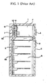
- FIG. 1 is a sectional view showing the inner structure of a refrigerator with a conventional blowing apparatus mounted therein.
- the refrigerator generally comprises an outer case 1 and an inner case 3.
- the inner case 3 is partitioned into an upper inner case section and a lower inner case section at a predetermined height.
- a freezing chamber F In the upper inner case section is disposed a freezing chamber F, and in the lower inner case section is disposed a refrigerating chamber R.
- doors 5 and 6 To the fronts of the freezing chamber F and the refrigerating chamber R are pivotably attached doors 5 and 6 for allowing foodstuffs to be put into and taken out of the freezing chamber F and the refrigerating chamber R, respectively.
- a machinery chamber M At the rear of the freezing chamber F is disposed a machinery chamber M, in which an evaporator 7, which constitutes a refrigerating cycle, and a blowing apparatus 10 that circulates cool air generated by means of the evaporator 7 are disposed.
- the operation of the refrigerator as described above is as follows: When the blowing apparatus 10 is operated, cool air, cooled by passing through the evaporator 7, is supplied to the freezing chamber F and the refrigerating chamber R via cool air supply channels 8a and 8b, respectively, and then flows toward the evaporator 7 though a cool air collection channel 9. In this way, the cool air is circulated by means of the blowing apparatus 10 in the refrigerator.
- FIG. 2 is a sectional view showing the conventional blowing apparatus mounted in the refrigerator shown in FIG. 1 .
- a channel separation plate 16 which separates the cool air supply channel 8a from the machinery chamber M, is disposed in parallel with the inner case 3.
- a cool air introduction hole 17 for allowing the cool air to be introduced from the machinery chamber M to the cool air supply channel 8a therethrough.
- an axial fan 14 that generates a blowing force.
- the axial fan 14 is rotated by means of a motor 12 mounted in the machinery chamber M.
- the axial fan 14 is rotated as the motor 12 is operated.
- cool air having passed through the evaporator 7 is introduced from the machinery chamber M to the cool air supply channel 8a.
- the cool air introduced to the cool air supply channel 8a is supplied to the freezing chamber F and the refrigerating chamber R, respectively.
- the axial fan 14 is disposed at the rear of the inner case 3 defining the cool air supply channel 8a. For this reason, when the axial fan 14 is operated, cool air runs against the inner case 3 and is then dispersed in all directions. As a result, flow loss, i.e., energy loss, is increased. Also, an extreme whirlpool phenomenon occurs around the rear of the introduction hole 17 due to flow characteristics of the axial fan 14. Consequently, flow loss is further increased, and noise is further increased.
- French patent application publication FR 2467309 describes a radial flow ventilator with a bladed impeller that is shielded at a side adjacent to an inlet nozzle by a shroud ring.
- the ring overlaps the inlet nozzle with an annular clearance.
- the curve that determines the shape of the ring can be parabolic or hyperbolic.
- German patent application publication DE 1204774 presents a radial flow blower suitable for conveying gases having high dust content.
- the blades are bent backwardly and the blade angle is the same or substantially the same at all points.
- a device adapted to impart a substantial whirl in an assisting direction is arranged on the input side of the blower rotor.
- United States patent application publication US 2002/0110455 A1 discloses a turbo fan of a ceiling-embedded cassette type air conditioner.
- the turbo fan has a shroud for guiding a fluid and a hub that has an outer diameter which is smaller than an inner diameter of the shroud, so as to facilitate an integral injection molding of the turbo fan.
- the fan furthermore includes blades extending between the shroud and the hub and being perpendicular to the shroud and the hub. Each of the blades has an inner diameter decreasingly inclined from the shroud to the hub, so that a quantity of sucked-air and a static pressure can be increased.
- United Kingdom patent GB 710391 introduces a radial flow impeller, for machines such as centrifugal fans, blowers or compressors having the discharge portions of the blades thereof forwardly inclined with respect to the direction of rotation of the impeller.
- the impeller includes blades of streamline (aerofoil) section. These blades are so relatively located that their pitch is determined by a radial line tangent to the trailing surface of a blade passing substantially through the tip of the discharge edge of the following blade reckoned in the direction of rotation of the impeller.
- United States patent US 5,741,118 shows a multiblade radial fan.
- r0 is the inside radius of the impeller
- r1 is the outside radius of the impeller
- n is the number of radially-directed blades
- t is the thickness of the radially-directed blades.
- the present invention has been made in view of the above problems, and it is an object of the present invention to provide a blowing apparatus for refrigerators that is capable of blowing cool air using a centrifugal fan, instead of the conventional axial fan, to minimize flow loss, whereby energy consumption is reduced, noise is decreased, and thus the refrigerator is quietly operated.
- a blowing apparatus for refrigerators including a centrifugal fan
- the centrifugal fan comprises: a hub plate connected to a shaft of the motor; a plurality of blades attached to the hub plate in the radial direction of the hub plate for forcing cool air to flow; and a ring-shaped shroud connected to ends of the blades, and wherein the ratio of the inner diameter of the centrifugal fan, formed through connection of the inner ends of the blades, to the outer diameter of the centrifugal fan, formed through connection of the outer ends of the blades, is 0.63+/-0.01.
- the inlet angle where each of the blades contacts the tangent line of the inner diameter of the centrifugal fan, formed through connection of the inner ends of the blades, is 32° ⁇ 1.
- the outlet angle where each of the blades contacts the tangent line of the outer diameter of the centrifugal fan, formed through connection of the outer ends of the blades, is 41° ⁇ 1.
- the solidity i.e., the ratio of the chord, the shortest distance between the inner end and the outer end of each of the blades, to the pitch, the circumferential distance between the outer end of one blade and the outer end of another adjacent blade, is 0.9 ⁇ 0.1.
- the blowing apparatus for refrigerators further comprises: a channel separation plate to separate a cool air flow space into two cool air flow parts, the channel separation plate having a cool air introduction hole, the centrifugal fan being disposed around the cool air introduction hole for discharging the cool air introduced through the cool air introduction hole in the circumferential direction of the centrifugal fan.
- the channel separation plate is disposed in parallel with an inner case forming an inner wall of a refrigerator for defining a cool air supply channel.
- the centrifugal fan is used instead of the axial fan to supply cool air. Consequently, the present invention has the effect of minimizing flow loss. As a result, energy consumption is reduced, noise is decreased, and thus the refrigerator is quietly operated.
- FIG. 3 is a sectional view showing a blowing apparatus according to a preferred embodiment of the present invention mounted in a refrigerator.
- a centrifugal fan 60 is used, instead of the conventional axial fan as described above, according to the present invention.
- a channel separation plate 52 which separates a cool air supply channel 55 from a machinery chamber M, is disposed in parallel with an inner case 50 of the refrigerator. At the channel separation plate 52 is formed a cool air introduction hole 53 where the centrifugal fan 60 is disposed.
- the channel separation plate 52 is provided around the cool air introduction hole 53 with a bell-mouth part 54 having a convex section. Cool air introduced through the cool air introduction hole 53 is more efficiently introduced into the cool air supply channel 55 by means of the bell-mouth part 54. The end of the bell-mouth part 54 is bent toward the centrifugal fan 60.
- the centrifugal fan 60 is disposed around the cool air introduction hole 53 for discharging the cool air introduced through the cool air introduction hole 53 along the cool air supply channel 55 in the circumferential direction of the centrifugal fan 60. Specifically, the centrifugal fan 60 is disposed in the cool air supply channel 55 at the rear of the cool air introduction hole 53 in the flow direction of cool air. In the machinery chamber M is mounted a motor 70 that drives the centrifugal fan 60.
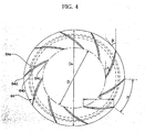
- FIG. 4 is a front view showing a centrifugal fan of the blowing apparatus for refrigerators according to the preferred embodiment of the present invention shown in FIG. 3
- FIG. 5 is a side view, in section, showing the centrifugal fan of the blowing apparatus for refrigerators according to the preferred embodiment of the present invention shown in FIG. 3 .
- the centrifugal fan 60 comprises: a hub plate 62, to which a shaft 73 of the motor 70 is connected (Refer to FIG. 3 ); a plurality of blades 64 attached to the hub plate 62 in the radial direction of the hub plate 62 for forcing cool air to flow; and a ring-shaped shroud 66 connected to ends of the blades 64.
- the shaft 73 of the motor 70 is connected to the center part of the hub plate 62.
- the hub plate 62 is disposed in parallel with the inner case 50.
- each of the blades 64 comprises: a positive pressure surface 64a where cool air is pushed outward; and a negative pressure surface 64b, disposed at the rear of the positive pressure surface 64a, where pressure below atmospheric pressure is created.
- Each of the blades 64 further comprises: a front edge part 64c contacting the cool air introduced through the cool air introduction hole 53; and a rear edge part 64d connected to the front edge part 64c in a streamline. The cool air is discharged outward by means of the rear edge parts 62d.
- the shroud 66 serves to guide the cool air such that the cool air introduced through the cool air introduction hole 53 can be discharged.
- the shroud 66 is provided with a cool air introduction-side end 66a, which is spaced a predetermined distance from the inside of the bell-mouth part 54 such that the cool air introduced through the cool air introduction hole 53 can flow into the cool air supply channel 55 more smoothly.
- the centrifugal fan 60 is designed such that the ratio Di/Do of the inner diameter Di of the centrifugal fan 60, which is formed through connection of the inner ends of the blades 64, to the outer diameter Do of the centrifugal fan 60, which is formed through connection of the outer ends of the blades 64, is 0.63 ⁇ 0.01.
- the inlet angle ⁇ at which each of the blades 64 contacts the tangent line of the inner diameter Di of the centrifugal fan 60, which is formed through connection of the inner ends of the blades 64, is 32° ⁇ 1.
- the outlet angle ⁇ at which each of the blades 64 contacts the tangent line of the outer diameter Do of the centrifugal fan 60, which is formed through connection of the outer ends of the blades 64, is 41° ⁇ 1.
- the solidity i.e., the ratio C/P of the chord C, which is the shortest distance between the inner end and the outer end of each of the blades 64, to the pitch P, which is the circumferential distance between the outer end of one blade 64 and the outer end of another adjacent blade 64, is 0.9 ⁇ 0.1.
- cool air having passed through the evaporator (not shown) is forced to flow to the cool air supply channel 55 by means of a blowing force of the centrifugal fan 60.
- the cool air guided to the cool air supply channel 55 is supplied to the freezing chamber and the refrigerating chamber.
- the cool air introduced into the center part of the centrifugal fan 60 through the cool air introduction hole 53 is discharged in the circumferential direction while passing between the blades 64, and is then introduced into the cool air supply channel 55.
- the cool air flows in the refrigerator while flow loss is minimized, since the centrifugal fan 60 is used instead of the conventional axial fan. Consequently, power consumption is reduced, and noise is decreased.
- FIG. 6 is a graph illustrating comparison of noise generation between the conventional axial fan and the centrifugal fan according to present invention
- FIG. 7 is a graph illustrating comparison of power consumption between the conventional axial fan and the centrifugal fan according to present invention.
- noise generated from the centrifugal fan 60 according to the present invention was 3 dB(A) less than that of the conventional axial fan, and power consumption of the centrifugal fan 60 according to the present invention was 28 % less than that of the conventional axial fan, under the condition that the amount of air was 0.82 CMM (m 3 /min).
- the present invention provides a blowing apparatus for refrigerators that is capable of blowing cool air using a centrifugal fan, instead of the conventional axial fan, to minimize flow loss. Consequently, the present invention has the effect that energy consumption is reduced, noise is decreased, and thus the refrigerator is quietly operated.
- the ratio Di/Do of the inner diameter Di of the centrifugal fan 60 to the outer diameter Do of the centrifugal fan 60 is 0.63 ⁇ 0.01
- the inlet angle ⁇ of each of the blades 64 is 32° ⁇ 1
- the outlet angle ⁇ of each of the blades 64 is 41° ⁇ 1
- the solidity of each of the blades 64 is 0.9 ⁇ 0.1.
Landscapes
- Engineering & Computer Science (AREA)
- Mechanical Engineering (AREA)
- General Engineering & Computer Science (AREA)
- Chemical & Material Sciences (AREA)
- Combustion & Propulsion (AREA)
- Physics & Mathematics (AREA)
- Thermal Sciences (AREA)
- Structures Of Non-Positive Displacement Pumps (AREA)
- Cold Air Circulating Systems And Constructional Details In Refrigerators (AREA)
Claims (3)
- Gebläsevorrichtung für Kühlschränke, die einen Radialventilator (60) umfasst, wobei der Radialventilator (60) Folgendes umfasst:eine Nabenplatte (62), die mit einer Motorwelle (70) verbunden ist;mehrere Schaufeln (64), die an der Nabenplatte (62) in radialer Richtung der Nabenplatte (62) befestigt sind, um einen Strom kalter Luft zu erzwingen; undeine ringförmige Abdeckung (66), die mit den Enden der Schaufeln (64) verbunden ist,wobei das Verhältnis (Di/Do) des Innendurchmessers (Di) des Radialventilators (60), wobei der Innendurchmesser des Radialventilators (60) durch Verbinden der inneren Enden der Schaufeln (64) konstant gebildet ist, zu dem Außendurchmesser (Do) des Radialventilators (60), wobei der Außendurchmesser (Do) des Radialventilators (60) durch Verbinden der äußeren Enden der Schaufeln (64) konstant gebildet ist, 0,63 ± 0,01 beträgt,der Austrittswinkel, unter dem jede der Schaufeln (64) die Tangente des Außendurchmessers (Do) des Radialventilators (60), der durch Verbinden der äußeren Enden der Schaufeln (64) gebildet ist, berührt, 41 ° ± 1 ° beträgt; undder Eintrittswinkel, unter dem jede der Schaufeln (64) die Tangente des Innendurchmessers (Di) des Radialventilators (60), der durch Verbinden der inneren Enden der Schaufeln (64) gebildet ist, berührt, 32 ° ± 1 ° beträgt,dadurch gekennzeichnet, dass die Festigkeit, d. h. das Verhältnis (C/P) der Sehne (C), d. h. dem kürzesten Abstand zwischen dem inneren Ende und dem äußeren Ende von jeder Schaufel (64), zu der Teilung (P), d. h. dem Umlaufabstand zwischen dem äußeren Ende einer Schaufel (64) und dem äußeren Ende einer benachbarten Schaufel (64), 0,9 ± 0,1 beträgt.
- Vorrichtung nach Anspruch 1, die ferner Folgendes umfasst:eine Kanaltrennplatte (52), um einen Durchflussraum für kalte Luft in zwei Durchflussteile für kalte Luft zu trennen, wobei die Kanaltrennplatte (52) ein Einlassloch für kalte Luft (53) besitzt,wobei der Radialventilator (60) um das Einlassloch für kalte Luft (53) herum angeordnet ist,wobei der Radialventilator (60) um das Einlassloch für kalte Luft (53) herum angeordnet ist, um die kalte Luft, die durch das Einlassloch für kalte Luft (53) eingelassen wird, in die Umlaufrichtung des Radialventilators (60) zu fördern.
- Vorrichtung nach Anspruch 2, wobei die Kanaltrennplatte (52) parallel zu einem inneren Gehäuse (50) angeordnet ist, das eine innere Wand eines Kühlschranks bildet, um einen Versorgungskanal für kalte Luft (55) zu definieren.
Applications Claiming Priority (2)
| Application Number | Priority Date | Filing Date | Title |
|---|---|---|---|
| KR2003100238 | 2003-12-30 | ||
| KR1020030100238A KR100550529B1 (ko) | 2003-12-30 | 2003-12-30 | 냉장고용 원심팬 |
Publications (3)
| Publication Number | Publication Date |
|---|---|
| EP1550811A2 EP1550811A2 (de) | 2005-07-06 |
| EP1550811A3 EP1550811A3 (de) | 2011-11-23 |
| EP1550811B1 true EP1550811B1 (de) | 2015-08-26 |
Family
ID=34567854
Family Applications (1)
| Application Number | Title | Priority Date | Filing Date |
|---|---|---|---|
| EP04028478.8A Expired - Lifetime EP1550811B1 (de) | 2003-12-30 | 2004-12-01 | Lüfter für Kühlschränke |
Country Status (3)
| Country | Link |
|---|---|
| US (1) | US7281898B2 (de) |
| EP (1) | EP1550811B1 (de) |
| KR (1) | KR100550529B1 (de) |
Families Citing this family (31)
| Publication number | Priority date | Publication date | Assignee | Title |
|---|---|---|---|---|
| DE102005005977A1 (de) * | 2005-02-09 | 2006-08-10 | Behr Gmbh & Co. Kg | Axiallüfter |
| JP4700414B2 (ja) * | 2005-06-02 | 2011-06-15 | 本田技研工業株式会社 | 空冷内燃機関用多翼ファン |
| US20070092375A1 (en) * | 2005-10-21 | 2007-04-26 | King Jih Enterprise Corp. | Circumferential air conditioning fan |
| AU2013202608B2 (en) * | 2005-10-28 | 2015-05-14 | Resmed Motor Technologies Inc. | Single or Multiple Stage Blower and Nested Volute(s) and/or Impeller(s) Therefor |
| US8393320B2 (en) | 2005-10-28 | 2013-03-12 | Resmed Limited | Blower motor with flexible support sleeve |
| KR100811488B1 (ko) * | 2006-05-19 | 2008-03-07 | 엘지전자 주식회사 | 냉장고 |
| KR100778481B1 (ko) * | 2006-07-07 | 2007-11-21 | 엘지전자 주식회사 | 냉장고용 냉기공급장치 및 이를 적용한 냉장고 |
| WO2008047962A1 (en) | 2006-10-19 | 2008-04-24 | Lg Electronics Inc. | Turbo fan for blowing and refrigerator having the same |
| CN101529178A (zh) * | 2006-10-19 | 2009-09-09 | Lg电子株式会社 | 用于冰箱的冷气供应装置及具有该冷气供应装置的冰箱 |
| KR100850958B1 (ko) * | 2007-04-04 | 2008-08-08 | 엘지전자 주식회사 | 냉장고 |
| KR100850959B1 (ko) | 2007-04-04 | 2008-08-12 | 엘지전자 주식회사 | 송풍장치 및 송풍장치가 구비된 냉장고 |
| JP2010196694A (ja) * | 2009-01-30 | 2010-09-09 | Sanyo Electric Co Ltd | 遠心式送風機、及び空気調和装置 |
| US8382427B2 (en) * | 2009-03-13 | 2013-02-26 | Sunonwealth Electric Machine Industry Co., Ltd. | Blower fan |
| JP2010285956A (ja) * | 2009-06-12 | 2010-12-24 | Sanyo Denki Co Ltd | 遠心ファン |
| UA107094C2 (xx) | 2009-11-03 | 2014-11-25 | Відцентровий стельовий вентилятор | |
| KR101270899B1 (ko) * | 2010-08-09 | 2013-06-07 | 엘지전자 주식회사 | 임펠러 및 이를 포함하는 원심 압축기 |
| US9039362B2 (en) * | 2011-03-14 | 2015-05-26 | Minebea Co., Ltd. | Impeller and centrifugal fan using the same |
| DE102011006251A1 (de) * | 2011-03-28 | 2012-10-04 | BSH Bosch und Siemens Hausgeräte GmbH | Kältegerät mit Lüfter |
| JP2013064347A (ja) * | 2011-09-16 | 2013-04-11 | Seiko Epson Corp | 遠心ファンおよびプロジェクター |
| KR101400665B1 (ko) * | 2012-06-12 | 2014-05-27 | 선문대학교 산학협력단 | 원심형 송풍장치 |
| CN103673465B (zh) * | 2012-09-12 | 2015-11-25 | 青岛海尔模具有限公司 | 用于大容积风冷冰箱的送风系统及风冷冰箱 |
| WO2014040267A1 (zh) * | 2012-09-14 | 2014-03-20 | 海信(北京)电器有限公司 | 离心风机冰箱的风道设计方法 |
| KR20140075301A (ko) * | 2012-12-11 | 2014-06-19 | 동부대우전자 주식회사 | 냉장고 |
| EP2765373B1 (de) * | 2013-02-06 | 2019-08-14 | LG Electronics Inc. | Verkleidung für Kühlschrank |
| KR101521703B1 (ko) * | 2013-07-31 | 2015-05-19 | 삼성전기주식회사 | 전동 송풍기용 원심 팬 |
| CN103953488A (zh) * | 2013-08-23 | 2014-07-30 | 邹旭 | 反冲叶轮发动机 |
| US10100839B2 (en) * | 2013-12-11 | 2018-10-16 | Keihin Corporation | Centrifugal fan |
| KR101577875B1 (ko) * | 2013-12-30 | 2015-12-28 | 동부대우전자 주식회사 | 냉장고용 원심팬 |
| CN104792095B (zh) * | 2015-04-30 | 2017-10-27 | 合肥华凌股份有限公司 | 冰箱 |
| KR102645031B1 (ko) * | 2016-10-24 | 2024-03-07 | 엘지전자 주식회사 | 냉장고용 송풍팬 |
| CN106593946B (zh) * | 2016-11-08 | 2019-05-03 | 青岛海尔股份有限公司 | 离心风机及具有该离心风机的风冷冰箱 |
Family Cites Families (11)
| Publication number | Priority date | Publication date | Assignee | Title |
|---|---|---|---|---|
| GB710391A (en) | 1952-06-11 | 1954-06-09 | Howden James & Co Ltd | Improvements in radial flow impellers |
| DE1204774B (de) | 1954-01-27 | 1965-11-11 | Bruno Eck Dr Ing | Radialgeblaese zur Foerderung stark staubhaltiger Gase |
| US3316729A (en) * | 1965-07-19 | 1967-05-02 | Gen Motors Corp | Defrosting system with food compartment shunt switch |
| JPS5239315Y1 (de) * | 1970-12-31 | 1977-09-06 | ||
| DE2940773C2 (de) | 1979-10-08 | 1986-08-14 | Punker GmbH, 2330 Eckernförde | Hochleistungs-Radialventilator |
| KR960703203A (ko) | 1994-04-28 | 1996-06-19 | 시게후치 마사토시 | 다익(多翼) 레이디얼 팬의 설계 방법 및 그 다익 레이디얼 팬(multivane radial fan designing method and multivane radial fan) |
| US5964576A (en) * | 1996-07-26 | 1999-10-12 | Japan Servo Co., Ltd. | Impeller of centrifugal fan |
| US6299409B1 (en) * | 1998-04-10 | 2001-10-09 | Denso Corporation | Centrifugal type blower unit |
| US6042335A (en) * | 1998-05-04 | 2000-03-28 | Carrier Corporation | Centrifugal flow fan and fan/orifice assembly |
| KR100405981B1 (ko) | 2001-02-12 | 2003-11-14 | 엘지전자 주식회사 | 천정형 공조기의 터보팬 구조 |
| JP2003090298A (ja) * | 2001-09-17 | 2003-03-28 | Nippon Soken Inc | 遠心ファン |
-
2003
- 2003-12-30 KR KR1020030100238A patent/KR100550529B1/ko not_active Expired - Fee Related
-
2004
- 2004-12-01 EP EP04028478.8A patent/EP1550811B1/de not_active Expired - Lifetime
- 2004-12-13 US US11/009,037 patent/US7281898B2/en not_active Expired - Fee Related
Also Published As
| Publication number | Publication date |
|---|---|
| US7281898B2 (en) | 2007-10-16 |
| US20050152781A1 (en) | 2005-07-14 |
| KR100550529B1 (ko) | 2006-02-10 |
| KR20050070559A (ko) | 2005-07-07 |
| EP1550811A3 (de) | 2011-11-23 |
| EP1550811A2 (de) | 2005-07-06 |
Similar Documents
| Publication | Publication Date | Title |
|---|---|---|
| EP1550811B1 (de) | Lüfter für Kühlschränke | |
| KR101577875B1 (ko) | 냉장고용 원심팬 | |
| KR100934556B1 (ko) | 원심 팬 및 이것을 이용한 공기 조화기 | |
| US6863500B2 (en) | Blast fan | |
| US20120045323A1 (en) | Fan | |
| KR100421382B1 (ko) | 터보팬 | |
| US11209011B2 (en) | Air conditioner | |
| KR20070101642A (ko) | 터보팬 | |
| KR100468468B1 (ko) | 공기조화기의 실내기 | |
| EP1326482B1 (de) | Kühlgebläse für Mikrowellenofen | |
| KR100572863B1 (ko) | 공기조화기용 터보팬 | |
| JPH07253267A (ja) | 冷凍冷蔵庫の通風構造 | |
| US7930897B2 (en) | Window type air conditioner | |
| KR100600713B1 (ko) | 냉장고용 원심팬 | |
| KR100420519B1 (ko) | 냉장고용 복합팬 | |
| KR100613497B1 (ko) | 냉장고의 냉기순환용 송풍장치 | |
| WO2005040686A2 (en) | Window type air conditioner | |
| KR100459191B1 (ko) | 터보팬 | |
| JPH10141291A (ja) | 遠心式送風機 | |
| KR100477454B1 (ko) | 공기조화기용 터보팬 | |
| KR101871723B1 (ko) | 실내기 및 그것을 구비하는 공기조화기 | |
| KR100442271B1 (ko) | 터보팬 구조 | |
| KR100789813B1 (ko) | 크로스플로우 팬 | |
| CN118088487A (zh) | 一种离心风扇 | |
| KR100789815B1 (ko) | 크로스플로우 팬의 경계판 구조 |
Legal Events
| Date | Code | Title | Description |
|---|---|---|---|
| PUAI | Public reference made under article 153(3) epc to a published international application that has entered the european phase |
Free format text: ORIGINAL CODE: 0009012 |
|
| 17P | Request for examination filed |
Effective date: 20041201 |
|
| AK | Designated contracting states |
Kind code of ref document: A2 Designated state(s): AT BE BG CH CY CZ DE DK EE ES FI FR GB GR HU IE IS IT LI LT LU MC NL PL PT RO SE SI SK TR |
|
| AX | Request for extension of the european patent |
Extension state: AL BA HR LV MK YU |
|
| PUAL | Search report despatched |
Free format text: ORIGINAL CODE: 0009013 |
|
| AK | Designated contracting states |
Kind code of ref document: A3 Designated state(s): AT BE BG CH CY CZ DE DK EE ES FI FR GB GR HU IE IS IT LI LT LU MC NL PL PT RO SE SI SK TR |
|
| AX | Request for extension of the european patent |
Extension state: AL BA HR LV MK YU |
|
| RIC1 | Information provided on ipc code assigned before grant |
Ipc: F04D 29/28 20060101AFI20111019BHEP Ipc: F04D 29/42 20060101ALI20111019BHEP |
|
| AKX | Designation fees paid |
Designated state(s): DE FR GB |
|
| 17Q | First examination report despatched |
Effective date: 20120727 |
|
| GRAP | Despatch of communication of intention to grant a patent |
Free format text: ORIGINAL CODE: EPIDOSNIGR1 |
|
| INTG | Intention to grant announced |
Effective date: 20141021 |
|
| RAP1 | Party data changed (applicant data changed or rights of an application transferred) |
Owner name: LG ELECTRONICS INC. |
|
| GRAS | Grant fee paid |
Free format text: ORIGINAL CODE: EPIDOSNIGR3 |
|
| GRAP | Despatch of communication of intention to grant a patent |
Free format text: ORIGINAL CODE: EPIDOSNIGR1 |
|
| INTG | Intention to grant announced |
Effective date: 20150325 |
|
| GRAA | (expected) grant |
Free format text: ORIGINAL CODE: 0009210 |
|
| AK | Designated contracting states |
Kind code of ref document: B1 Designated state(s): DE FR GB |
|
| REG | Reference to a national code |
Ref country code: GB Ref legal event code: FG4D |
|
| REG | Reference to a national code |
Ref country code: DE Ref legal event code: R096 Ref document number: 602004047749 Country of ref document: DE |
|
| REG | Reference to a national code |
Ref country code: FR Ref legal event code: PLFP Year of fee payment: 12 |
|
| REG | Reference to a national code |
Ref country code: DE Ref legal event code: R097 Ref document number: 602004047749 Country of ref document: DE |
|
| PLBE | No opposition filed within time limit |
Free format text: ORIGINAL CODE: 0009261 |
|
| STAA | Information on the status of an ep patent application or granted ep patent |
Free format text: STATUS: NO OPPOSITION FILED WITHIN TIME LIMIT |
|
| 26N | No opposition filed |
Effective date: 20160530 |
|
| REG | Reference to a national code |
Ref country code: FR Ref legal event code: PLFP Year of fee payment: 13 |
|
| PGFP | Annual fee paid to national office [announced via postgrant information from national office to epo] |
Ref country code: DE Payment date: 20161107 Year of fee payment: 13 Ref country code: GB Payment date: 20161110 Year of fee payment: 13 Ref country code: FR Payment date: 20161114 Year of fee payment: 13 |
|
| REG | Reference to a national code |
Ref country code: DE Ref legal event code: R119 Ref document number: 602004047749 Country of ref document: DE |
|
| GBPC | Gb: european patent ceased through non-payment of renewal fee |
Effective date: 20171201 |
|
| REG | Reference to a national code |
Ref country code: FR Ref legal event code: ST Effective date: 20180831 |
|
| PG25 | Lapsed in a contracting state [announced via postgrant information from national office to epo] |
Ref country code: DE Free format text: LAPSE BECAUSE OF NON-PAYMENT OF DUE FEES Effective date: 20180703 Ref country code: FR Free format text: LAPSE BECAUSE OF NON-PAYMENT OF DUE FEES Effective date: 20180102 |
|
| PG25 | Lapsed in a contracting state [announced via postgrant information from national office to epo] |
Ref country code: GB Free format text: LAPSE BECAUSE OF NON-PAYMENT OF DUE FEES Effective date: 20171201 |