EP1550755B1 - Ultrasonic washing apparatus - Google Patents
Ultrasonic washing apparatus Download PDFInfo
- Publication number
- EP1550755B1 EP1550755B1 EP03753998A EP03753998A EP1550755B1 EP 1550755 B1 EP1550755 B1 EP 1550755B1 EP 03753998 A EP03753998 A EP 03753998A EP 03753998 A EP03753998 A EP 03753998A EP 1550755 B1 EP1550755 B1 EP 1550755B1
- Authority
- EP
- European Patent Office
- Prior art keywords
- washing apparatus
- ultrasonic
- main unit
- ultrasonic washing
- support arm
- Prior art date
- Legal status (The legal status is an assumption and is not a legal conclusion. Google has not performed a legal analysis and makes no representation as to the accuracy of the status listed.)
- Expired - Lifetime
Links
- 238000005406 washing Methods 0.000 title claims description 151
- 239000007788 liquid Substances 0.000 claims description 25
- XLYOFNOQVPJJNP-UHFFFAOYSA-N water Substances O XLYOFNOQVPJJNP-UHFFFAOYSA-N 0.000 claims description 16
- 230000002401 inhibitory effect Effects 0.000 claims description 2
- 238000010276 construction Methods 0.000 description 15
- 238000006073 displacement reaction Methods 0.000 description 8
- 238000004140 cleaning Methods 0.000 description 4
- 230000037303 wrinkles Effects 0.000 description 4
- 241000252254 Catostomidae Species 0.000 description 2
- XEEYBQQBJWHFJM-UHFFFAOYSA-N Iron Chemical compound [Fe] XEEYBQQBJWHFJM-UHFFFAOYSA-N 0.000 description 2
- 230000005540 biological transmission Effects 0.000 description 2
- 230000006835 compression Effects 0.000 description 2
- 238000007906 compression Methods 0.000 description 2
- 230000008878 coupling Effects 0.000 description 2
- 238000010168 coupling process Methods 0.000 description 2
- 238000005859 coupling reaction Methods 0.000 description 2
- 230000000694 effects Effects 0.000 description 2
- 229920003002 synthetic resin Polymers 0.000 description 2
- 239000000057 synthetic resin Substances 0.000 description 2
- 239000008399 tap water Substances 0.000 description 2
- 235000020679 tap water Nutrition 0.000 description 2
- 239000004753 textile Substances 0.000 description 2
- 239000002699 waste material Substances 0.000 description 2
- 239000000853 adhesive Substances 0.000 description 1
- 230000001070 adhesive effect Effects 0.000 description 1
- 239000002390 adhesive tape Substances 0.000 description 1
- 239000003292 glue Substances 0.000 description 1
- 229910052742 iron Inorganic materials 0.000 description 1
- 239000000463 material Substances 0.000 description 1
- 239000002184 metal Substances 0.000 description 1
- 229910052751 metal Inorganic materials 0.000 description 1
- 238000002360 preparation method Methods 0.000 description 1
- 238000004904 shortening Methods 0.000 description 1
- 238000002791 soaking Methods 0.000 description 1
- 239000000126 substance Substances 0.000 description 1
- 238000002604 ultrasonography Methods 0.000 description 1
Images





Classifications
-
- D—TEXTILES; PAPER
- D06—TREATMENT OF TEXTILES OR THE LIKE; LAUNDERING; FLEXIBLE MATERIALS NOT OTHERWISE PROVIDED FOR
- D06F—LAUNDERING, DRYING, IRONING, PRESSING OR FOLDING TEXTILE ARTICLES
- D06F19/00—Washing machines using vibrations for washing purposes
-
- D—TEXTILES; PAPER
- D06—TREATMENT OF TEXTILES OR THE LIKE; LAUNDERING; FLEXIBLE MATERIALS NOT OTHERWISE PROVIDED FOR
- D06F—LAUNDERING, DRYING, IRONING, PRESSING OR FOLDING TEXTILE ARTICLES
- D06F7/00—Washing devices adapted to be used independently of any particular receptacle, e.g. for removable mounting on wash-tubs, bath-tubs, or the like
- D06F7/04—Washing devices adapted to be used independently of any particular receptacle, e.g. for removable mounting on wash-tubs, bath-tubs, or the like of the vibrator type
-
- B—PERFORMING OPERATIONS; TRANSPORTING
- B08—CLEANING
- B08B—CLEANING IN GENERAL; PREVENTION OF FOULING IN GENERAL
- B08B3/00—Cleaning by methods involving the use or presence of liquid or steam
- B08B3/04—Cleaning involving contact with liquid
- B08B3/10—Cleaning involving contact with liquid with additional treatment of the liquid or of the object being cleaned, e.g. by heat, by electricity or by vibration
- B08B3/12—Cleaning involving contact with liquid with additional treatment of the liquid or of the object being cleaned, e.g. by heat, by electricity or by vibration by sonic or ultrasonic vibrations
-
- D—TEXTILES; PAPER
- D06—TREATMENT OF TEXTILES OR THE LIKE; LAUNDERING; FLEXIBLE MATERIALS NOT OTHERWISE PROVIDED FOR
- D06F—LAUNDERING, DRYING, IRONING, PRESSING OR FOLDING TEXTILE ARTICLES
- D06F35/00—Washing machines, apparatus, or methods not otherwise provided for
-
- D—TEXTILES; PAPER
- D06—TREATMENT OF TEXTILES OR THE LIKE; LAUNDERING; FLEXIBLE MATERIALS NOT OTHERWISE PROVIDED FOR
- D06F—LAUNDERING, DRYING, IRONING, PRESSING OR FOLDING TEXTILE ARTICLES
- D06F5/00—Hand implements for washing purposes, e.g. sticks
- D06F5/02—Plungers, dollies, pounders, squeezers, or the like
- D06F5/04—Plungers, dollies, pounders, squeezers, or the like adapted for removable mounting on receptacles such as wash-tubs
Definitions
- the present invention relates to an ultrasonic washing apparatus that permits partial washing of textile articles.
- Japanese Patent Applications Laid-Open Nos. 2001-310094 and 2001-310165 disclose handy ultrasonic washing apparatuses. These apparatuses have an ultrasonic horn joined to an ultrasonic vibrator housed in a hand-held casing, and achieve washing with the tip of the ultrasonic horn kept in contact with an article to be cleaned that has been soaked in washing liquid so as to be imbued therewith.
- the power source is a battery housed in the casing.
- a washing machine with a partial washing apparatus which has a supersonic resonator driven by an oscillator to generate supersonic vibration and a supersonic vibration horn is disclosed.
- a washing liquid is fed to the partial washing apparatus so as to be agitated by supersonic waves and then fed to an article to be washed to achieve partial washing thereof.
- the partial washing apparatus is detachably fitted to the washing machine proper at approximately the center of the lid thereof.
- the partial washing apparatus may be used as a handy-type partial washing apparatus when held at the grip portion thereof.
- the disclosed partial washing apparatus is a part of the washing machine and cannot used by its own.
- a washing machine with a part washing device is also disclosed in WO 02/075034 .
- the part washing device is mounted on the outer surface of the main body receiving a washing tank.
- the part washing device takes a use position and a non-use position, such that in the use position the cleaning section faces to the laundry charging port from outside the main body, and in the non-use position the cleaning section is retracted from the position where it faces to the laundry charging port.
- the cleaning section performs cleaning by ultrasonic waves emitted from an ultrasonic vibration device.
- the part washing device is not enabled to be used by its own, but is fixed to a washing machine, which is adapted to hold such a part washing device. Therefore the disclosed part washing device can only be used by especially prepared washing machines.
- JP 2000061192 an ultrasonic washing machine's operability is improved by making it possible to house the machine in the periphery part of a washing machine main body excepting for a using time so as to operate the main body of the ultrasonic washing machine at the center upper part of a washing tank.
- the ultrasonic washing machine is not able to be used by its own and is fixed in a special way to the washing machine.
- An object of the present invention is to provide an ultrasonic washing apparatus which offers a high ultrasonic vibration output combined with a versatility that makes it usable at any place and which allows effective washing in so short a time as not to cause the user to feel fatigue.
- the ultrasonic washing apparatus can be fitted at a desired place when used, and the user does not need to take it into consideration to hold it with the hand when performing washing.
- lightweightedness is no longer an essential factor.
- the ultrasonic washing apparatus can be fitted not with a compact, lightweight, thus low-output ultrasonic vibrator unit but a large, high-output one. This makes it possible to transmit an ultrasonic wave with a high energy level over a wide area, and thus perform effective washing in a short time Since the user does not need to support the weight of the ultrasonic washing apparatus, he or she feels less fatigue.
- the user can use both hands, he or she can hold an article to be cleaned sufficiently tense so as not to develop wrinkles or twists. This makes it possible to adjust how the article is pressed against the ultrasound vibration horn so that they are kept in optimal contact with each other, and thereby to make the most of the washing ability of the ultrasonic washing apparatus.
- the ultrasonic vibration horn is provided with the liquid feeder that feeds it with liquid, it is possible to perform washing while keeping the spot to be cleaned optimally wet. This eliminates the need to dampen the article to be cleaned as a whole beforehand by soaking it in the liquid.
- the fitter includes at least one bar-shaped or plate-shaped support arm having fitting portions the interval between which can be varied according to the size of the target object to which to fit.
- the ultrasonic washing apparatus can easily be fitted to a target object with a comparatively long fitting span, such as a washing machine or kitchen sink.
- the ultrasonic washing apparatus can be fitted stably, as if a man stretching his legs to stand firm.
- the support arm is telescopic, and the interval between the fitting portions is varied as a result of the support arm extending and contracting. This helps widen the choice of places at which the ultrasonic washing apparatus can be fitted.
- the support arm is biased by a spring in the direction of the telescopic displacement thereof.
- the support arm can be locked in a state telescopically displaced to a desired length.
- the telescopic displacement of the support arm can be locked at a desired length, and thus the support arm can be fixed firmly so as not to get loose from the target object.
- a slidable fitting portion is fitted outside the support arm so that, the interval between the fitting portions is varied as a result of the slidable fitting portion sliding. This helps widen the choice of places at which the ultrasonic washing apparatus can be fitted.
- the slidable fitting portion is biased by a spring in a direction in which the slidable fitting portion can slide.
- the slidable fitting portion can be locked in a desired position.
- the sliding of the fitting portion can be locked in a desired position, and thus the support arm can be fixed firmly so as not to get loose from the target object.
- the posture of the main unit relative toe the fitter can be changed.
- the posture of the main unit can be adjusted so that the user can perform washing in a comfortable posture.
- the ultrasonic washing apparatus When the ultrasonic washing apparatus is not used, it can be retracted into an unobtrusive posture, i.e., into a retracted posture.
- a lock for inhibiting change of the posture of the main unit in the ultrasonic washing apparatus as described above, there is provided a lock for inhibiting change of the posture of the main unit.
- the position of the main unit relative to the fitter can be changed.
- the position of the main unit can be adjusted so that the user can perform washing in a convenient position.
- the ultrasonic washing apparatus When the ultrasonic washing apparatus is not used, it can be retracted into an unobtrusive position, i.e., into a retracted position.
- the main unit is removable from the fitter.
- the main unit can be removed from the fitter so that the user can perform washing while holding it with the hand. This makes it possible to freely set the relative position between the washing apparatus and the article to be cleaned, and thus helps further widen the application of the washing apparatus.
- a water receiving portion for feeding water simultaneously to the liquid feeder and elsewhere.
- Fig. 1 shows a vertical section of a main unit 10 of an ultrasonic washing apparatus 1
- Fig. 2 shows the front appearance of an ultrasonic vibration horn 21.
- the main unit 10 is combined with an fitter 30 and other elements as shown in Figs. 5 to 10 to build various embodiments.
- the main unit 10 has a casing 11 made of synthetic resin.
- the casing 11 has the shape of a horizontally extending arm, of which one end serves as a root portion thereof. This portion is coupled to a base 31 made of synthetic resin.
- the base 31 forms part of an fitter 30.
- the fitter 30 permits the main unit 10 to be fitted to a desired place.
- "a desired place” denotes "any of the places where the fitter is usable.” That is, the expression does not mean any place without any restrictions or requirements at all. Specifically how the fitter 30 is shaped and structured will be described later with reference to Figs. 5 to 10 .
- a vertical stud shaft 32 stands on the base 31, and the stud shaft 32 supports the main unit 10 in such a way that it can rotate in a horizontal plane.
- An anchor screw 12 is screwed into the stud shaft 32 to prevent the main unit 10 from dropping therefrom.
- the main unit 10 is provided with a lock 13 that engages with the stud shaft 32. When the lock 13 is acting, it inhibits the rotation of the main unit 10.
- the lock 13 is pressed against the stud shaft 32 by an unillustrated spring.
- the lock 13 unlocks when a force stronger than a predetermined level is applied to the main unit 10.
- the lock 13 may be so structured that it can be operated from outside to unlock.
- the ultrasonic vibration horn 21 has substantially the shape of the letter T brought down sideways, and a head portion 22 thereof, located at one end thereof, is partially exposed through an opening 14 formed in the bottom face of the casing 11.
- Projections 23 are formed so as to protrude from both side faces of the head portion 22.
- the projections 23 are formed at a zero-vibration point, i.e., a node point of vibration transmission.
- a drive circuit 25 for driving the ultrasonic vibrator 20 is fitted on the outside of the casing 11.
- An unillustrated power cable runs out of the drive circuit 25 and is connected to commercially distributed electric power.
- the drive circuit 25 may be housed inside the casing 11. Alternatively, the drive circuit 25 may be housed inside the fitter 30. This permits the drive circuit 25 and the main unit 10 or the fitter 30 to be built into a single unit, and thus helps achieve a compact construction and a consolidated design as a whole.
- the head portion 22 of the ultrasonic vibration horn 21 is provided with a liquid feeder 26.
- the liquid feeder 26 is realized with a tube that runs out of the base 31 through 1 to a side of the head portion 22.
- the liquid feeder 26 is connected to an unillustrated tap water faucet, washing liquid tank, or the like.
- the wiring between the drive circuit 25 and the ultrasonic vibrator 20 and the piping for the liquid feeder 26 are laid in such a way as not to hamper the rotation of the main unit 10.
- a force stronger than a predetermined level is applied to the main unit 10 to unlock it.
- the lock 13 locks again to inhibit the rotation of the main unit 10.
- electric power starts to be supplied to the drive circuit 25 to start ultrasonic washing.
- Water starts to be supplied to the liquid feeder 26 to perform ultrasonic washing while making the article to be cleaned damp with a predetermined amount of water.
- the user holds the article to be cleaned with both hands, and presses it against the head portion 22 while holding it tense so as not to develop wrinkles or twists.
- the ultrasonic energy causes cavitation in the damp portion of the article and thereby removes dirt therefrom.
- the amount of liquid fed from the liquid feeder 26 is so set as to make the washing spot optimally damp.
- the main unit 10 is locked by the lock 13, and thus remains in position even as the article is moved. This permits washing to be performed steadily.
- Figs. 3 and 4 show a modified example of the ultrasonic washing apparatus 1.
- Fig. 3 shows a vertical section of the main unit 10 of the ultrasonic washing apparatus 1
- Fig. 4 shows the front appearance of the ultrasonic vibration horn 21.
- the ultrasonic vibration horn 21 is of the straight transmission type. That is, the ultrasonic vibrator 20 is provided right above the ultrasonic vibration horn 21 so that the ultrasonic vibrator 20 makes the ultrasonic vibration horn 21 vibrate just in the same manner as does the ultrasonic vibrator 20 itself
- the ultrasonic vibration horn 21 and the ultrasonic vibrator 20 are supported by the flange portion 24 of the ultrasonic vibration horn 21.
- Fig. 5 shows, in a perspective view, the ultrasonic washing apparatus 1 representing background art that is useful for understanding the invention.
- the fitter 30 has a fitting portion 33 with a C-shaped sectional shape.
- the fitting portion 33 is so designed as to mount snugly on the rim of a kitchen sink 50. Simply mounting the fitting portion 33 on the rim of the sink 50 permits the ultrasonic washing apparatus 1 to be fitted in position.
- the fitting portion 33 may be provided with a screw so that it can be fixed by being tightened with the screw.
- the fitting portion 33 may be fixed more firmly by being bonded with glue or adhesive tape.
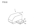
- Fig. 6 shows, in a perspective view, the ultrasonic washing apparatus 1 representing background art that is useful for understanding the invention.
- the fitter 30 has a fitting portion 34 shaped like a flat plate.
- a sticker 35 is provided on the bottom face of the fitting portion 34.
- the sticker 35 is realized with a permanent magnet.
- the magnetic attractive force of the sticker 35 permits the fitter 30 to be fitted to a target object so long as it is made of a magnetic metal such as iron.
- the bottom face of the fitting portion 34 may be entirely covered with a single large piece of magnet, or may be strewn with a plurality of small pieces of magnet.
- the permanent magnet is so arranged that its height relative to the fitting portion 34 is variable so that, through operation of a lever or the like, the permanent magnet can be moved closer to or away from the target object.
- a strong attractive force acts to permit the fitting portion 34 to be fixed firmly; when the permanent magnet is moved away from the target object, the attractive force weakens to permit the fitting portion 34 removed easily. This further enhances the usability.
- the sticker 35 may be realized with a sucker so that the fitting portion 34 can be fixed to a flat surface of any material.
- a sucker it is possible to use one or two large suckers, or a large number of small suckers. It is also possible to permit switching of the state of the sucker, between a sucking and a non-sucking state, by permitting the shape thereof to be changed through operation of a lever or the like.
- the sticker 35 may be realized with an adhesive substance (such as is used in glued paper tags for clerical use) that permits repeated fitting and removal.
- Fig. 7 shows, in a perspective view, the ultrasonic washing apparatus 1 of a first embodiment of the invention.
- the fitter 30 includes a bar-shaped or plate-shaped support arm 36. There may be provided one or more of the support arm 36.
- the support arm 36 is made so long as to cover the width of full-automatic and two-tub washing machines available on the market.
- the support arm 36 is composed of two parallel arm portions coupled together, and is so structured that it can be telescopically displaced. Specifically, in each arm portion, an inner arm 38 is slidably placed inside an outer arm 37. A lock screw 39 for pressing the front-side inner arm 38 is screwed into the front-side outer arm 37 so that, by tightening the lock screw 39, the telescopic displacement of the support arm 36 can be locked at a desired length.
- a desired length denotes any length within the stroke of the displacement of the support arm 36.
- fitting portions 40 are shaped like a downward bent hook. Putting across the top face of a full-automatic washing machine 51 the support arm 36 in its telescopically lengthened state with the lock screw 39 loosened, then telescopically shortening the support arm 36 until the fitting portions 40 at both ends firmly grip the full-automatic washing machine 51, and then tightening the lock screw 39 to lock the telescopic displacement of the support arm 36 permits the ultrasonic washing apparatus 1 to be fitted in position. This makes it possible to firmly fix the fitter 30 so that it does not get loose from the full-automatic washing machine 51.
- a spring may be inserted between the outer and inner arms 37 and 38 so that the support arm 36 is biased by the spring in the direction of telescopic displacement.
- the outer and inner arms 37 and 38 are coupled together with a tension coil spring 41 so that the support arm 36 is biased thereby in the direction in which it is telescopically shortened.
- the lock screw 39 may be used together. Specifically, after the fitting portions 40 grip the full-automatic washing machine 51, the lock screw 39 is tightened to lock the telescopic displacement of the support arm 36. This permits the ultrasonic washing apparatus 1 to be fitted even more firmly.
- a compression coil spring may be inserted so that the support arm 36 acts like a contractible rod.
- Fig. 8 shows, in a perspective view, the ultrasonic washing apparatus 1 of a second embodiment of the invention.
- This embodiment is a modified version of the first embodiment.
- the fitter 30 includes a support arm 36 composed of two parallel arm portions coupled together, but this support arm 36 is not telescopic but instead has a slider-type fitting portion 47 at one end.
- a fitting portion 40 which is, as in the third embodiment, shaped like a downward bent hook.
- a lock screw 39 for pressing the support arm 36 is screwed into the fitting portion 47 so that, by tightening this lock screw 39, the fitting portion 47 can be locked at a desired position on the support arm 36.
- the fitting portion 47 With the lock screw 39 loosened, the fitting portion 47 is slid to the end of the support arm 36, and then the support arm 36 in this state is put across the top face of a full-automatic washing machine 51. Then the fitting portion 47 is slid to a position where it together with the fitting portions 40 firmly grips the full-automatic washing machine 51, and then the lock screw 39 is tightened to lock the sliding of the fitting portion 47.
- a spring may be inserted between the support arm 36 and the fitting portion 47 so that the fitting portion 47 is biased by the spring toward the middle of the support arm 36 (the portion thereof where the main unit 10 is located) or in the direction opposite thereto.
- the support arm 36 and the fitting portion 47 are coupled together with a tension coil spring 41 so that the fitting portion 47 is biased thereby toward the middle of the support arm 36.
- the lock screw 39 may be used together. Specifically, after the fitting portions 40 and 47 grip the full-automatic washing machine 51, the lock screw 39 is tightened to lock the sliding of the fitting portion 47. This permits the ultrasonic washing apparatus 1 to be fitted even more firmly.
- a compression coil spring may be inserted so that the fitting portion 47 is biased thereby outward
- the posture of the main unit 10 relative to the fitter 30 can be changed.
- the main unit 10 can be rotated to an angle at which it does not hamper the washing of dishes or hand washing of laundry.
- the ultrasonic washing apparatus 1 is fitted to a full-automatic washing machine 51 as shown in Figs. 7 and 8
- the main unit 10 can be rotated to an angle at which it does not hamper the passage of laundry into and out of the full-automatic washing machine 51.
- the main unit 10 may additionally be so structured as to be movable relative to the fitter 30.
- the position of the main unit 10 relative to the support arm 36 (in Fig. 7 , relative to the outer arm 37 of the support arm 36) can be changed. This permits the position of the main unit 10 to be changed so that washing can be performed with the main unit 10 placed in a convenient position.
- the main unit 10 can be retracted into an unobtrusive position, i.e., a retracted position.
- the main unit 10 is removable from the fitter 30. With the anchor screw 12 unscrewed, the main unit 10 can be removed from the stud shaft 32, and can be carried to a place away from the fitter 30 so that washing can be performed with the main unit 10 held with the hand.
- a coupler of another type than the anchor screw 12 may be used to make the fitting and removal of the main unit 10 easier.
- the main unit 10 By coupling the main unit 10 and the fitter 30 together by a coupling tube or the like, it is possible to maintain the supply of electric power and water from the fitter 30 to the main unit 10 even when the main unit 10 is removed from the fitter 30.
- the main unit 10 may be provided with a rechargeable power source and a water tank so as to operate on a cordless basis.
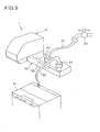
- Fig. 9 shows, in a perspective view, the ultrasonic washing apparatus 1 of a third embodiment of the invention.
- the fitter 30 (of any of the first to second embodiments) is additionally provided with a water receiving portion 42.
- the water receiving portion 42 is connected to a tap water faucet 60 by way of a hose 61, and feeds water simultaneously to the liquid feeder 26 and to a connection port 43 provided by the side of the water receiving portion 42.
- connection port 43 By connecting the connection port 43 to a full-automatic washing machine 51 by a hose 62, even if there is only one faucet 60, it is possible to use the ultrasonic washing apparatus 1 and the full-automatic washing machine 51 simultaneously. By providing more connection ports 43, it is possible to feed water to a larger number of appliances or places.
- Fig. 10 shows, in a perspective view, the ultrasonic washing apparatus 1 representing background art that is useful for understanding the invention.
- the main unit 10 is combined with a tray 44.
- the tray 44 has a drain port 45 formed at one place in the bottom face thereof, and the drain port 45 is plugged with a plug 46.
- the liquid fed from the liquid feeder 26 is collected in the tray 44. This makes it possible to use the ultrasonic washing apparatus 1 even at a place where the liquid cannot be discharged on the spot. On completion of washing, the ultrasonic washing apparatus 1 is carried to a place where the liquid can be discharged, and then the plug 46 is pulled off to complete the disposal of waste liquid. Making the tray 44 removable from the main unit 10 makes the disposal of waste liquid easier.
- the present invention finds wide application in households and businesses as a simple and convenient washing apparatus for washing textile articles.
Landscapes
- Engineering & Computer Science (AREA)
- Textile Engineering (AREA)
- Accessory Of Washing/Drying Machine, Commercial Washing/Drying Machine, Other Washing/Drying Machine (AREA)
- Cleaning By Liquid Or Steam (AREA)
Description
- The present invention relates to an ultrasonic washing apparatus that permits partial washing of textile articles.
- There have conventionally been proposed many apparatuses that achieve washing by exploiting ultrasonic waves.
Japanese Patent Applications Laid-Open Nos. 2001-310094 2001-310165 - These conventional ultrasonic washing apparatuses boast their compactness and light weight, and accordingly produce a rather low output of ultrasonic vibration. Thus, to obtain a satisfactory washing effect, they need to be passed over and over across the article to be cleaned. Compact and lightweight as these apparatuses are, repeating such operation causes fatigue in the user's hand. Moreover, since the user needs to use one hand to hold the ultrasonic washing apparatus, he or she needs to hold the article to be cleaned with the other hand alone. This makes it impossible to hold the article tense, resulting in wrinkles and twists developing therein as the ultrasonic washing apparatus is passed across it. With wrinkles or twists in the article, the ultrasonic horn cannot be kept in optimal contact with the article. This not only hampers obtaining the expected washing effect, but also tends to result in the article being cleaned unevenly or imperfectly in wrinkled or twisted parts thereof.
- In
US 2002/0134117 A1 a washing machine with a partial washing apparatus, which has a supersonic resonator driven by an oscillator to generate supersonic vibration and a supersonic vibration horn is disclosed. A washing liquid is fed to the partial washing apparatus so as to be agitated by supersonic waves and then fed to an article to be washed to achieve partial washing thereof. The partial washing apparatus is detachably fitted to the washing machine proper at approximately the center of the lid thereof. The partial washing apparatus may be used as a handy-type partial washing apparatus when held at the grip portion thereof. The disclosed partial washing apparatus is a part of the washing machine and cannot used by its own. - A washing machine with a part washing device is also disclosed in
WO 02/075034 - In
JP 2000061192 - An object of the present invention is to provide an ultrasonic washing apparatus which offers a high ultrasonic vibration output combined with a versatility that makes it usable at any place and which allows effective washing in so short a time as not to cause the user to feel fatigue.
- According to the present invention, this object is achieved by the features of
claim 1. With this construction,the ultrasonic washing apparatus can be fitted at a desired place when used, and the user does not need to take it into consideration to hold it with the hand when performing washing. Thus, lightweightedness is no longer an essential factor. Accordingly, the ultrasonic washing apparatus can be fitted not with a compact, lightweight, thus low-output ultrasonic vibrator unit but a large, high-output one. This makes it possible to transmit an ultrasonic wave with a high energy level over a wide area, and thus perform effective washing in a short time Since the user does not need to support the weight of the ultrasonic washing apparatus, he or she feels less fatigue. Moreover, since the user can use both hands, he or she can hold an article to be cleaned sufficiently tense so as not to develop wrinkles or twists. This makes it possible to adjust how the article is pressed against the ultrasound vibration horn so that they are kept in optimal contact with each other, and thereby to make the most of the washing ability of the ultrasonic washing apparatus. Moreover, since the ultrasonic vibration horn is provided with the liquid feeder that feeds it with liquid, it is possible to perform washing while keeping the spot to be cleaned optimally wet. This eliminates the need to dampen the article to be cleaned as a whole beforehand by soaking it in the liquid. - By building the drive circuit along with the main unit of the fitter into a unit, it is possible to achive a compact overall construction and a neat design.
- According to the present invention, the fitter includes at least one bar-shaped or plate-shaped support arm having fitting portions the interval between which can be varied according to the size of the target object to which to fit. With this construction, the ultrasonic washing apparatus can easily be fitted to a target object with a comparatively long fitting span, such as a washing machine or kitchen sink. The ultrasonic washing apparatus can be fitted stably, as if a man stretching his legs to stand firm.
- According to a preferred embodiment of the present invention, the support arm is telescopic, and the interval between the fitting portions is varied as a result of the support arm extending and contracting. This helps widen the choice of places at which the ultrasonic washing apparatus can be fitted.
- According to a further preferred embodiment of the present invention, the support arm is biased by a spring in the direction of the telescopic displacement thereof. With this construction, without adjusting the support arm precisely to the length of the target object, simply by putting the fitting portions at both ends of the support arm on the target object, the support arm can be fixed to the target object by the force of the spring. This permits easy and quick fixing of the ultrasonic washing apparatus.
- According to a further preferred embodiment of the present invention, the support arm can be locked in a state telescopically displaced to a desired length. With this construction, the telescopic displacement of the support arm can be locked at a desired length, and thus the support arm can be fixed firmly so as not to get loose from the target object.
- According to a further preferred embodiment of the present invention, outside the support arm, a slidable fitting portion is fitted so that, the interval between the fitting portions is varied as a result of the slidable fitting portion sliding. This helps widen the choice of places at which the ultrasonic washing apparatus can be fitted.
- According to a further preferred embodiment of the present invention, the slidable fitting portion is biased by a spring in a direction in which the slidable fitting portion can slide. With this construction, without adjusting the position of the fitting portion precisely to suit the size of the target object, simply by putting the fitting portion on the target object, the support arm can be fixed to the target object by the force of the spring. This permits easy and quick fitting of the ultrasonic washing apparatus.
- According to a further preferred embodiment of the present invention, the slidable fitting portion can be locked in a desired position. With this construction, the sliding of the fitting portion can be locked in a desired position, and thus the support arm can be fixed firmly so as not to get loose from the target object.
- According to a further preferred embodiment of the present invention, the posture of the main unit relative toe the fitter can be changed. With this construction, the posture of the main unit can be adjusted so that the user can perform washing in a comfortable posture. When the ultrasonic washing apparatus is not used, it can be retracted into an unobtrusive posture, i.e., into a retracted posture.
- According to a further preferred embodiment of the present invention, in the ultrasonic washing apparatus as described above, there is provided a lock for inhibiting change of the posture of the main unit. With this construction, when the main unit needs to be kept in a particular posture as during washing or when retracted, it can be locked in that position so as to remain steady. This permits washing to be performed steadily during washing, and prevents the main unit from moving unexpectedly and hitting another object when retracted.
- According to a further preferred embodiment of the present invention, the position of the main unit relative to the fitter can be changed. With this construction, the position of the main unit can be adjusted so that the user can perform washing in a convenient position. When the ultrasonic washing apparatus is not used, it can be retracted into an unobtrusive position, i.e., into a retracted position.
- According to a further preferred embodiment of the present invention, the main unit is removable from the fitter. With this construction, whenever necessary, the main unit can be removed from the fitter so that the user can perform washing while holding it with the hand. This makes it possible to freely set the relative position between the washing apparatus and the article to be cleaned, and thus helps further widen the application of the washing apparatus.
- According to a further preferred embodiment of the present invention, in the ultrasonic washing apparatus as described above, there is provided a water receiving portion for feeding water simultaneously to the liquid feeder and elsewhere. With this construction, in a case where there is another appliance or a place that requires water, it is possible to operate the ultrasonic washing apparatus while feeding water also to that appliance of place. This makes it possible to share a single faucet, for example, with a washing machine.
-
-
Fig. 1 is a vertical sectional view of the main unit of an ultrasonic washing apparatus. -
Fig. 2 is a front view of the ultrasonic vibration horn shown inFig. 1 . -
Fig. 3 is a vertical sectional view of a modified example of the main unit of an ultrasonic washing apparatus. -
Fig. 4 is a front view of the ultrasonic vibration horn shown inFig. 3 . -
Fig. 5 is a perspective view of an ultrasonic washing apparatus representing background art that is useful for understanding the invention. -
Fig. 6 is a perspective view of an ultrasonic washing apparatus representing background art that is useful for understanding the invention. -
Fig. 7 is a perspective view of the ultrasonic washing apparatus of a first embodiment of the invention. -
Fig. 8 is a perspective view of the ultrasonic washing apparatus of a second embodiment of the invention. -
Fig. 9 is a perspective view of the ultrasonic washing apparatus of a third embodiment of the invention. -
Fig. 10 is a perspective view of an ultrasonic washing apparatus representing background art that is useful for understanding the invention. - Hereinafter, embodiments of the present invention will be described with reference to
Figs. 1 to 10 . -
Fig. 1 shows a vertical section of amain unit 10 of anultrasonic washing apparatus 1, andFig. 2 shows the front appearance of anultrasonic vibration horn 21. Themain unit 10 is combined with an fitter 30 and other elements as shown inFigs. 5 to 10 to build various embodiments. - The
main unit 10 has acasing 11 made of synthetic resin. Thecasing 11 has the shape of a horizontally extending arm, of which one end serves as a root portion thereof. This portion is coupled to a base 31 made of synthetic resin. The base 31 forms part of an fitter 30. The fitter 30 permits themain unit 10 to be fitted to a desired place. Throughout the present specification, "a desired place" denotes "any of the places where the fitter is usable." That is, the expression does not mean any place without any restrictions or requirements at all. Specifically how the fitter 30 is shaped and structured will be described later with reference toFigs. 5 to 10 . - A
vertical stud shaft 32 stands on thebase 31, and thestud shaft 32 supports themain unit 10 in such a way that it can rotate in a horizontal plane. Ananchor screw 12 is screwed into thestud shaft 32 to prevent themain unit 10 from dropping therefrom. Themain unit 10 is provided with alock 13 that engages with thestud shaft 32. When thelock 13 is acting, it inhibits the rotation of themain unit 10. Thelock 13 is pressed against thestud shaft 32 by an unillustrated spring. Thelock 13 unlocks when a force stronger than a predetermined level is applied to themain unit 10. Thus, themain unit 10 can be rotated by applying a force stronger than a predetermined level from outside. Thelock 13 may be so structured that it can be operated from outside to unlock. - Inside the
casing 11, there are arranged anultrasonic vibrator 20 and anultrasonic vibration horn 21 joined thereto. Theultrasonic vibration horn 21 has substantially the shape of the letter T brought down sideways, and ahead portion 22 thereof, located at one end thereof, is partially exposed through anopening 14 formed in the bottom face of thecasing 11.Projections 23 are formed so as to protrude from both side faces of thehead portion 22. Theprojections 23 are formed at a zero-vibration point, i.e., a node point of vibration transmission. Theseprojections 23, together with aflange portion 24 of theultrasonic vibration horn 21, serve to support theultrasonic vibrator 20 and theultrasonic vibration horn 21. - A
drive circuit 25 for driving theultrasonic vibrator 20 is fitted on the outside of thecasing 11. An unillustrated power cable runs out of thedrive circuit 25 and is connected to commercially distributed electric power. - The
drive circuit 25 may be housed inside thecasing 11. Alternatively, thedrive circuit 25 may be housed inside the fitter 30. This permits thedrive circuit 25 and themain unit 10 or the fitter 30 to be built into a single unit, and thus helps achieve a compact construction and a consolidated design as a whole. - The
head portion 22 of theultrasonic vibration horn 21 is provided with aliquid feeder 26. Theliquid feeder 26 is realized with a tube that runs out of the base 31 through 1 to a side of thehead portion 22. Theliquid feeder 26 is connected to an unillustrated tap water faucet, washing liquid tank, or the like. - The wiring between the
drive circuit 25 and theultrasonic vibrator 20 and the piping for theliquid feeder 26 are laid in such a way as not to hamper the rotation of themain unit 10. - Next, how the
ultrasonic washing apparatus 1 is used will be described. A force stronger than a predetermined level is applied to themain unit 10 to unlock it. When the posture of themain unit 10 is changed up to the angle at which to perform washing, thelock 13 locks again to inhibit the rotation of themain unit 10. After these preparations, electric power starts to be supplied to thedrive circuit 25 to start ultrasonic washing. Water starts to be supplied to theliquid feeder 26 to perform ultrasonic washing while making the article to be cleaned damp with a predetermined amount of water. - The user holds the article to be cleaned with both hands, and presses it against the
head portion 22 while holding it tense so as not to develop wrinkles or twists. In this state, as the article is moved slowly, the ultrasonic energy causes cavitation in the damp portion of the article and thereby removes dirt therefrom. The amount of liquid fed from theliquid feeder 26 is so set as to make the washing spot optimally damp. Themain unit 10 is locked by thelock 13, and thus remains in position even as the article is moved. This permits washing to be performed steadily. - When the article has been cleaned satisfactorily, the supply of water to the
liquid feeder 26 and the supply of electric power to thedrive circuit 25 are stopped to finish washing. A force stronger than a predetermined level is applied to themain unit 10 to unlock it, and the posture of themain unit 10 is changed up to the angle into which to retract it. Thelock 13 then locks again to inhibit the rotation of themain unit 10. This prevents themain unit 10 in the retracted state from moving unexpectedly and hitting another object. -
Figs. 3 and4 show a modified example of theultrasonic washing apparatus 1.Fig. 3 shows a vertical section of themain unit 10 of theultrasonic washing apparatus 1, andFig. 4 shows the front appearance of theultrasonic vibration horn 21. - In the
ultrasonic washing apparatus 1 shown inFig. 3 , theultrasonic vibration horn 21 is of the straight transmission type. That is, theultrasonic vibrator 20 is provided right above theultrasonic vibration horn 21 so that theultrasonic vibrator 20 makes theultrasonic vibration horn 21 vibrate just in the same manner as does theultrasonic vibrator 20 itself Theultrasonic vibration horn 21 and theultrasonic vibrator 20 are supported by theflange portion 24 of theultrasonic vibration horn 21. - Now, how the
main unit 10 described is combined with the fitter 30 and other elements to build various embodiments of theultrasonic washing apparatus 1 will be described. -
Fig. 5 shows, in a perspective view, theultrasonic washing apparatus 1 representing background art that is useful for understanding the invention. In thiswashing apparatus 1 the fitter 30 has afitting portion 33 with a C-shaped sectional shape. Thefitting portion 33 is so designed as to mount snugly on the rim of akitchen sink 50. Simply mounting thefitting portion 33 on the rim of thesink 50 permits theultrasonic washing apparatus 1 to be fitted in position. Thefitting portion 33 may be provided with a screw so that it can be fixed by being tightened with the screw. Thefitting portion 33 may be fixed more firmly by being bonded with glue or adhesive tape. -
Fig. 6 shows, in a perspective view, theultrasonic washing apparatus 1 representing background art that is useful for understanding the invention. In thiswashing apparatus 1 the fitter 30 has afitting portion 34 shaped like a flat plate. Asticker 35 is provided on the bottom face of thefitting portion 34. Thesticker 35 is realized with a permanent magnet. Thus, the magnetic attractive force of thesticker 35 permits the fitter 30 to be fitted to a target object so long as it is made of a magnetic metal such as iron. - In a case where the
sticker 35 is realized with a permanent magnet, the bottom face of thefitting portion 34 may be entirely covered with a single large piece of magnet, or may be strewn with a plurality of small pieces of magnet. - Advisably, the permanent magnet is so arranged that its height relative to the
fitting portion 34 is variable so that, through operation of a lever or the like, the permanent magnet can be moved closer to or away from the target object. With this arrangement, when the permanent magnet is moved closer to the target object, a strong attractive force acts to permit thefitting portion 34 to be fixed firmly; when the permanent magnet is moved away from the target object, the attractive force weakens to permit thefitting portion 34 removed easily. This further enhances the usability. - The
sticker 35 may be realized with a sucker so that thefitting portion 34 can be fixed to a flat surface of any material. As the sucker, it is possible to use one or two large suckers, or a large number of small suckers. It is also possible to permit switching of the state of the sucker, between a sucking and a non-sucking state, by permitting the shape thereof to be changed through operation of a lever or the like. - The
sticker 35 may be realized with an adhesive substance (such as is used in glued paper tags for clerical use) that permits repeated fitting and removal. -
Fig. 7 shows, in a perspective view, theultrasonic washing apparatus 1 of a first embodiment of the invention. In this embodiment, the fitter 30 includes a bar-shaped or plate-shapedsupport arm 36. There may be provided one or more of thesupport arm 36. Thesupport arm 36 is made so long as to cover the width of full-automatic and two-tub washing machines available on the market. - The
support arm 36 is composed of two parallel arm portions coupled together, and is so structured that it can be telescopically displaced. Specifically, in each arm portion, aninner arm 38 is slidably placed inside anouter arm 37. Alock screw 39 for pressing the front-sideinner arm 38 is screwed into the front-sideouter arm 37 so that, by tightening thelock screw 39, the telescopic displacement of thesupport arm 36 can be locked at a desired length. Here, "a desired length" denotes any length within the stroke of the displacement of thesupport arm 36. - At the ends of the outer and
inner arms fitting portions 40. Thefitting portions 40 are shaped like a downward bent hook. Putting across the top face of a full-automatic washing machine 51 thesupport arm 36 in its telescopically lengthened state with thelock screw 39 loosened, then telescopically shortening thesupport arm 36 until thefitting portions 40 at both ends firmly grip the full-automatic washing machine 51, and then tightening thelock screw 39 to lock the telescopic displacement of thesupport arm 36 permits theultrasonic washing apparatus 1 to be fitted in position. This makes it possible to firmly fix the fitter 30 so that it does not get loose from the full-automatic washing machine 51. - A spring may be inserted between the outer and
inner arms support arm 36 is biased by the spring in the direction of telescopic displacement. For example, the outer andinner arms tension coil spring 41 so that thesupport arm 36 is biased thereby in the direction in which it is telescopically shortened. With this construction, after putting across the top face of the full-automatic washing machine 51 thesupport arm 36 in its state telescopically lengthened against the force exerted by the spring, simply letting it go causes thefitting portions 40 to automatically grip the full-automatic washing machine 51, and thus permits theultrasonic washing apparatus 1 to be fitted in position. - The
lock screw 39 may be used together. Specifically, after thefitting portions 40 grip the full-automatic washing machine 51, thelock screw 39 is tightened to lock the telescopic displacement of thesupport arm 36. This permits theultrasonic washing apparatus 1 to be fitted even more firmly. - Instead of the
tension coil spring 41, a compression coil spring may be inserted so that thesupport arm 36 acts like a contractible rod. - It is possible to set the range of the telescopic displacement of the
support arm 36 to cover not only full-automatic and two-tub washing machines but also kitchen sinks. -
Fig. 8 shows, in a perspective view, theultrasonic washing apparatus 1 of a second embodiment of the invention. This embodiment is a modified version of the first embodiment. Specifically, the fitter 30 includes asupport arm 36 composed of two parallel arm portions coupled together, but thissupport arm 36 is not telescopic but instead has a slider-type fitting portion 47 at one end. - At the other end of the
support arm 36, there is provided afitting portion 40, which is, as in the third embodiment, shaped like a downward bent hook. - A
lock screw 39 for pressing thesupport arm 36 is screwed into thefitting portion 47 so that, by tightening thislock screw 39, thefitting portion 47 can be locked at a desired position on thesupport arm 36. - With the
lock screw 39 loosened, thefitting portion 47 is slid to the end of thesupport arm 36, and then thesupport arm 36 in this state is put across the top face of a full-automatic washing machine 51. Then thefitting portion 47 is slid to a position where it together with thefitting portions 40 firmly grips the full-automatic washing machine 51, and then thelock screw 39 is tightened to lock the sliding of thefitting portion 47. This permits theultrasonic washing apparatus 1 to be fitted in position. This makes it possible to firmly fix the fitter 30 so that it does not get loose from the full-automatic washing machine 51. - A spring may be inserted between the
support arm 36 and thefitting portion 47 so that thefitting portion 47 is biased by the spring toward the middle of the support arm 36 (the portion thereof where themain unit 10 is located) or in the direction opposite thereto. For example, thesupport arm 36 and thefitting portion 47 are coupled together with atension coil spring 41 so that thefitting portion 47 is biased thereby toward the middle of thesupport arm 36. With this construction, after putting across the top face of the full-automatic washing machine 51 thesupport arm 36 with thefitting portion 47 slid against the force exerted by the spring, simply letting it go causes thefitting portions automatic washing machine 51, and thus permits theultrasonic washing apparatus 1 to be fitted in position. - The
lock screw 39 may be used together. Specifically, after thefitting portions automatic washing machine 51, thelock screw 39 is tightened to lock the sliding of thefitting portion 47. This permits theultrasonic washing apparatus 1 to be fitted even more firmly. - Instead of the
tension coil spring 41, a compression coil spring may be inserted so that thefitting portion 47 is biased thereby outward - It is possible to set the slide range of the
fitting portion 47 to cover not only full-automatic and two-tub washing machines but also kitchen sinks. - The posture of the
main unit 10 relative to the fitter 30 can be changed. When theultrasonic washing apparatus 1 is fitted to akitchen sink 50 as shown inFig. 5 , themain unit 10 can be rotated to an angle at which it does not hamper the washing of dishes or hand washing of laundry. When theultrasonic washing apparatus 1 is fitted to a full-automatic washing machine 51 as shown inFigs. 7 and8 , themain unit 10 can be rotated to an angle at which it does not hamper the passage of laundry into and out of the full-automatic washing machine 51. - In a case where the fitter 30 is long as in the first and second embodiments, the
main unit 10 may additionally be so structured as to be movable relative to the fitter 30. - Specifically, in the cases shown in
Figs. 7 and8 , the position of themain unit 10 relative to the support arm 36 (inFig. 7 , relative to theouter arm 37 of the support arm 36) can be changed. This permits the position of themain unit 10 to be changed so that washing can be performed with themain unit 10 placed in a convenient position. When not in use, themain unit 10 can be retracted into an unobtrusive position, i.e., a retracted position. - In all of the first to second embodiments, the
main unit 10 is removable from the fitter 30. With theanchor screw 12 unscrewed, themain unit 10 can be removed from thestud shaft 32, and can be carried to a place away from the fitter 30 so that washing can be performed with themain unit 10 held with the hand. A coupler of another type than theanchor screw 12 may be used to make the fitting and removal of themain unit 10 easier. - By coupling the
main unit 10 and the fitter 30 together by a coupling tube or the like, it is possible to maintain the supply of electric power and water from the fitter 30 to themain unit 10 even when themain unit 10 is removed from the fitter 30. Alternatively, themain unit 10 may be provided with a rechargeable power source and a water tank so as to operate on a cordless basis. -
Fig. 9 shows, in a perspective view, theultrasonic washing apparatus 1 of a third embodiment of the invention. In this embodiment, the fitter 30 (of any of the first to second embodiments) is additionally provided with awater receiving portion 42. Thewater receiving portion 42 is connected to atap water faucet 60 by way of ahose 61, and feeds water simultaneously to theliquid feeder 26 and to aconnection port 43 provided by the side of thewater receiving portion 42. - By connecting the
connection port 43 to a full-automatic washing machine 51 by ahose 62, even if there is only onefaucet 60, it is possible to use theultrasonic washing apparatus 1 and the full-automatic washing machine 51 simultaneously. By providingmore connection ports 43, it is possible to feed water to a larger number of appliances or places. -
Fig. 10 shows, in a perspective view, theultrasonic washing apparatus 1 representing background art that is useful for understanding the invention. In thiswashing apparatus 1 themain unit 10 is combined with atray 44. Thetray 44 has adrain port 45 formed at one place in the bottom face thereof, and thedrain port 45 is plugged with aplug 46. - The liquid fed from the
liquid feeder 26 is collected in thetray 44. This makes it possible to use theultrasonic washing apparatus 1 even at a place where the liquid cannot be discharged on the spot. On completion of washing, theultrasonic washing apparatus 1 is carried to a place where the liquid can be discharged, and then theplug 46 is pulled off to complete the disposal of waste liquid. Making thetray 44 removable from themain unit 10 makes the disposal of waste liquid easier. - The present invention finds wide application in households and businesses as a simple and convenient washing apparatus for washing textile articles.
Claims (12)
- An ultrasonic washing apparatus (1), comprising a main unit (10), an ultrasonic vibration horn (21) exposed out of the main unit (10), a liquid feeder (26) for feeding liquid to the ultrasonic vibration horn (21), a drive circuit (25) for driving the ultrasonic vibration horn (21) to produce ultrasonic vibration, and a fitter (30) for permitting the main unit (10) and the drive circuit (25) to be fitted at a desired place,
characterized in that
the fitter (30) includes at least one bar-shaped or plate-shaped support arm (36) having fitting portions (40, 47) whereby, an interval between the fitting portions (40,47) can be varied according to the width of a target object (51), such as a washing machine or kitchen sink, to stably fix the fitter (30) to the target object (51). - The ultrasonic washing apparatus (1) according to claim 1,
wherein the support arm (36) is telescopic, and the interval between the fitting portions (40) is varied as a result of the support arm (36) extending and contracting. - The ultrasonic washing apparatus (1) according to claim 2,
wherein the support arm (36) is biased by a spring (41) in either an extending or contracting direction thereof. - The ultrasonic washing apparatus (1) according to claim 2 or 3,
wherein the support arm (36) can be locked in a state extended or contracted to a desired length. - The ultrasonic washing apparatus (1) according to claim 1,
wherein, outside the support arm (36), a slidable fitting portion (47) is fitted so that, the interval between the fitting portions (40,47) is varied as a result of the slidable fitting portion (47) sliding. - The ultrasonic washing apparatus (1) according to claim 5,
wherein the slidable fitting portion (47) is biased by a spring (41) in one of directions in which the slidable fitting portion (47) can slide. - The ultrasonic washing apparatus (1) according to claim 5 or 6.
wherein the slidable fitting portion (47) can be locked in a desired position. - The ultrasonic washing apparatus (1) according to claim 1,
wherein a posture of the main unit (10) relative to the fitter (30) can be changed. - The ultrasonic washing apparatus (1) according to claim 8, further comprising a lock (13) for inhibiting change of the posture of the main unit (10).
- The ultrasonic washing apparatus (1) according to claim 1,
wherein a position of the main unit (10) relative to the fitter (30) can be changed. - The ultrasonic washing apparatus (1) according to claim 1,
wherein the main unit (10) is removable from the fitter (30). - The ultrasonic washing apparatus (1) according to claim 1,
further comprising a water receiving portion (42) for feeding water simultaneously to the liquid feeder (26) and elsewhere.
Applications Claiming Priority (3)
| Application Number | Priority Date | Filing Date | Title |
|---|---|---|---|
| JP2002293299A JP3957605B2 (en) | 2002-10-07 | 2002-10-07 | Ultrasonic cleaning equipment |
| JP2002293299 | 2002-10-07 | ||
| PCT/JP2003/012692 WO2004031469A1 (en) | 2002-10-07 | 2003-10-02 | Ultrasonic washing apparatus |
Publications (3)
| Publication Number | Publication Date |
|---|---|
| EP1550755A1 EP1550755A1 (en) | 2005-07-06 |
| EP1550755A4 EP1550755A4 (en) | 2005-12-14 |
| EP1550755B1 true EP1550755B1 (en) | 2008-03-12 |
Family
ID=32064005
Family Applications (1)
| Application Number | Title | Priority Date | Filing Date |
|---|---|---|---|
| EP03753998A Expired - Lifetime EP1550755B1 (en) | 2002-10-07 | 2003-10-02 | Ultrasonic washing apparatus |
Country Status (9)
| Country | Link |
|---|---|
| US (1) | US7493781B2 (en) |
| EP (1) | EP1550755B1 (en) |
| JP (1) | JP3957605B2 (en) |
| KR (1) | KR100596591B1 (en) |
| CN (1) | CN100500973C (en) |
| AU (1) | AU2003272922A1 (en) |
| DE (1) | DE60319720T2 (en) |
| TW (1) | TWI238212B (en) |
| WO (1) | WO2004031469A1 (en) |
Families Citing this family (50)
| Publication number | Priority date | Publication date | Assignee | Title |
|---|---|---|---|---|
| EP2312038A1 (en) * | 2005-01-14 | 2011-04-20 | Electrolux Home Products Corporation N.V. | Textile product treating apparatus having an ultrasonic cleaning device |
| ES2369374T3 (en) * | 2006-05-26 | 2011-11-30 | Electrolux Home Products Corporation N.V. | TEXTILE PRODUCTS TREATMENT EQUIPMENT WITH AN ULTRASONIC CLEANING DEVICE. |
| CN100457998C (en) * | 2006-06-19 | 2009-02-04 | 李怀校 | Ultrasonic washing machine |
| KR100800174B1 (en) * | 2006-10-20 | 2008-02-01 | 한국기계연구원 | Megasonic Cleaning Module |
| US7754026B2 (en) * | 2007-11-08 | 2010-07-13 | Whirlpool Corporation | Dishwasher with sonic cleaner |
| US7913561B2 (en) * | 2008-02-05 | 2011-03-29 | Olympus Medical Systems Corp. | Ultrasonic wave vibrating apparatus |
| DE102009012950A1 (en) | 2008-04-07 | 2009-10-08 | Heinz Herbertz | Textiles i.e. outerwear, cleaning method, involves producing bundled stream of suds, water and air by nozzle, which is moved by centrifugal force, and supplying processing agents through perforations of rotatable perforated cleaning drum |
| US8809806B1 (en) | 2011-11-07 | 2014-08-19 | Bill J. Deese | Portable sterilization assembly |
| ES2538901B1 (en) * | 2013-12-24 | 2016-05-03 | Bsh Electrodomésticos España, S.A. | Washing machine and method of using said washing machine |
| KR102280205B1 (en) | 2014-01-22 | 2021-07-22 | 삼성전자주식회사 | Washing machine |
| WO2015130046A1 (en) | 2014-02-28 | 2015-09-03 | 삼성전자주식회사 | Washing machine |
| US20160102425A1 (en) * | 2014-10-09 | 2016-04-14 | General Electric Company | Washing machine appliance spray hose assembly |
| US10655264B2 (en) | 2015-08-04 | 2020-05-19 | Whirlpool Corporation | Laundry treating appliance with internal housing |
| CN106073448B (en) * | 2016-08-24 | 2020-05-19 | 浙江健仕科技股份有限公司 | Wall breaking machine |
| JP6941314B2 (en) * | 2016-10-25 | 2021-09-29 | 青島海爾洗衣机有限公司QingDao Haier Washing Machine Co.,Ltd. | Ultrasonic cleaner and washing machine |
| EP3538704B1 (en) * | 2016-11-08 | 2020-10-07 | Arçelik Anonim Sirketi | A partial cleaning device suitable for use with a washing machine, a laundry cleaning system comprising the partial cleaning device and a control method for operating the laundry cleaning system |
| CN108505275B (en) * | 2017-02-28 | 2020-12-01 | 青岛海尔洗衣机有限公司 | Partial cleaning structure for clothes and washing machine |
| CN108729097B (en) * | 2017-04-25 | 2020-10-09 | 青岛胶南海尔洗衣机有限公司 | An ultrasonic cleaning device |
| CN108729096B (en) * | 2017-04-25 | 2020-09-15 | 青岛胶南海尔洗衣机有限公司 | Washing machine |
| CN108729095B (en) * | 2017-04-25 | 2021-03-02 | 青岛海尔洗衣机有限公司 | Portable ultrasonic washing device |
| CN108796950B (en) * | 2017-05-02 | 2020-12-29 | 青岛海尔洗衣机有限公司 | A hand-held laundry washing device |
| CN108866914B (en) * | 2017-05-15 | 2021-07-16 | 青岛胶南海尔洗衣机有限公司 | A wall-mounted ultrasonic cleaning device |
| CN108866912B (en) * | 2017-05-15 | 2021-05-04 | 青岛胶南海尔洗衣机有限公司 | A wall-mounted ultrasonic cleaning device |
| CN108866913B (en) * | 2017-05-15 | 2020-10-23 | 青岛海尔洗衣机有限公司 | A wall-mounted ultrasonic cleaning device |
| CN109137369B (en) * | 2017-06-16 | 2021-09-17 | 青岛胶南海尔洗衣机有限公司 | Wall-mounted ultrasonic cleaning device |
| CN109137365B (en) * | 2017-06-16 | 2021-11-16 | 天津海尔洗涤电器有限公司 | Ultrasonic washing device |
| CN109137368B (en) * | 2017-06-16 | 2021-09-17 | 天津海尔洗涤电器有限公司 | Ultrasonic washing device |
| CN109137367B (en) * | 2017-06-16 | 2021-11-16 | 青岛胶南海尔洗衣机有限公司 | Ultrasonic washing device |
| CN109137357B (en) * | 2017-06-27 | 2021-09-07 | 青岛胶南海尔洗衣机有限公司 | A washing machine with ultrasonic washing device |
| CN109137370B (en) * | 2017-06-27 | 2021-11-16 | 青岛海尔洗衣机有限公司 | Ultrasonic washing device |
| JP7133796B2 (en) * | 2017-06-29 | 2022-09-09 | 青島海爾洗衣机有限公司 | Ultrasonic cleaner and washing machine |
| JP7123313B2 (en) * | 2017-06-30 | 2022-08-23 | 青島海爾洗衣机有限公司 | ultrasonic cleaner |
| JP6913903B2 (en) * | 2017-06-30 | 2021-08-04 | 青島海爾洗衣机有限公司QingDao Haier Washing Machine Co.,Ltd. | Ultrasonic cleaner |
| CN109402937B (en) * | 2017-08-17 | 2022-01-18 | 重庆海尔洗衣机有限公司 | Ultrasonic washing device and control method |
| US11591740B2 (en) | 2018-01-31 | 2023-02-28 | Whirlpool Corporation | Dispensing system for a laundry treating appliance |
| JP7175461B2 (en) * | 2018-05-08 | 2022-11-21 | 青島海爾洗衣机有限公司 | ultrasonic cleaner |
| JP7190688B2 (en) * | 2018-05-08 | 2022-12-16 | 青島海爾洗衣机有限公司 | ultrasonic cleaner |
| CN110714294A (en) * | 2018-07-13 | 2020-01-21 | 青岛海尔洗衣机有限公司 | A kind of control method of ultrasonic cleaning device and ultrasonic cleaning device |
| JP7316864B2 (en) * | 2018-07-27 | 2023-07-28 | Asti株式会社 | Ultrasonic stapler and ultrasonic welding method |
| JP7217881B2 (en) * | 2018-12-21 | 2023-02-06 | 青島海爾洗衣机有限公司 | Ultrasonic cleaner and washing machine |
| CN109778479B (en) * | 2019-03-28 | 2024-05-31 | 天津工业大学 | Ultrasonic clothes cleaning machine and working method thereof |
| CN111979688B (en) * | 2019-05-24 | 2022-12-27 | 青岛海尔洗衣机有限公司 | Ultrasonic device |
| JP7398697B2 (en) * | 2019-08-05 | 2023-12-15 | 青島海爾洗衣机有限公司 | Ultrasonic cleaning equipment and washing machines |
| CN112680921A (en) * | 2019-10-18 | 2021-04-20 | 青岛海尔洗衣机有限公司 | Ultrasonic device and clothes treatment equipment |
| CN110685107B (en) * | 2019-10-18 | 2024-06-18 | 青岛海尔洗衣机有限公司 | Ultrasonic device and clothing treating apparatus |
| CN112680922B (en) * | 2019-10-18 | 2023-11-28 | 青岛海尔洗衣机有限公司 | Ultrasonic devices and laundry treatment equipment |
| CN111058215B (en) * | 2019-12-31 | 2021-04-20 | 西安交通大学 | A clothing cleaning device based on ultrasonic cavitation effect |
| JP2022178224A (en) * | 2021-05-19 | 2022-12-02 | 青島海爾洗衣机有限公司 | Ultrasonic cleaning device and washing machine |
| JP2024021677A (en) * | 2022-08-04 | 2024-02-16 | 青島海爾洗衣机有限公司 | washing machine |
| CN117072847A (en) * | 2023-08-17 | 2023-11-17 | 南通大学 | A kind of external auxiliary bracket for small ultrasonic oscillator |
Family Cites Families (19)
| Publication number | Priority date | Publication date | Assignee | Title |
|---|---|---|---|---|
| JPS5432980A (en) | 1977-08-19 | 1979-03-10 | Nec Corp | Calibrating method for testing device for switching time |
| JPS57122889A (en) * | 1981-01-21 | 1982-07-30 | Hitachi Ltd | Washing machine with washer for ultrasonic section |
| JPS5975266A (en) | 1982-10-25 | 1984-04-27 | Nippon Telegr & Teleph Corp <Ntt> | Color recording device |
| JPS6112494A (en) * | 1984-06-29 | 1986-01-20 | Nippon Kokan Kk <Nkk> | Mating section fastening device |
| JPS63114286A (en) | 1986-10-31 | 1988-05-19 | Toshiba Corp | Laser diode driving circuit |
| JPH03103091A (en) | 1989-09-18 | 1991-04-30 | Secoh Giken Inc | Three-phase reluctance motor |
| JPH05137992A (en) | 1991-11-19 | 1993-06-01 | Koji Toda | Ultrasonic stirrer |
| US5148848A (en) * | 1992-01-28 | 1992-09-22 | Carefree/Scott Fetzer Company | Lift assist mechanism for retractable awning |
| JPH06112494A (en) | 1992-09-29 | 1994-04-22 | Fuji Electric Co Ltd | Insulated gate bipolar transistor |
| JPH1157274A (en) | 1997-08-28 | 1999-03-02 | Sharp Corp | Washing machine |
| JP2000061192A (en) * | 1998-08-20 | 2000-02-29 | Sharp Corp | Washing machine |
| JP3530070B2 (en) | 1999-04-28 | 2004-05-24 | シャープ株式会社 | Part washing apparatus with a washing machine |
| TW457137B (en) | 1999-04-28 | 2001-10-01 | Sharp Kk | Washer having a partial washing apparatus |
| JP3596738B2 (en) | 1999-05-12 | 2004-12-02 | シャープ株式会社 | Part washing apparatus with a washing machine |
| JP2001310094A (en) | 2000-04-28 | 2001-11-06 | Kao Corp | Ultrasonic cleaning equipment |
| EP1149637B1 (en) * | 2000-04-28 | 2007-02-28 | Kao Corporation | Horn for ultrasonic cleaning apparatus |
| JP2001310165A (en) | 2000-04-28 | 2001-11-06 | Kao Corp | Ultrasonic cleaning equipment |
| JP2002191893A (en) | 2000-12-25 | 2002-07-10 | Kao Corp | Ultrasonic cleaning equipment |
| JP3739293B2 (en) | 2001-03-15 | 2006-01-25 | シャープ株式会社 | Washing machine |
-
2002
- 2002-10-07 JP JP2002293299A patent/JP3957605B2/en not_active Expired - Fee Related
-
2003
- 2003-10-02 EP EP03753998A patent/EP1550755B1/en not_active Expired - Lifetime
- 2003-10-02 CN CNB2003801002004A patent/CN100500973C/en not_active Expired - Fee Related
- 2003-10-02 WO PCT/JP2003/012692 patent/WO2004031469A1/en not_active Ceased
- 2003-10-02 US US10/507,803 patent/US7493781B2/en not_active Expired - Fee Related
- 2003-10-02 AU AU2003272922A patent/AU2003272922A1/en not_active Abandoned
- 2003-10-02 KR KR1020047012679A patent/KR100596591B1/en not_active Expired - Fee Related
- 2003-10-02 DE DE60319720T patent/DE60319720T2/en not_active Expired - Lifetime
- 2003-10-07 TW TW092127795A patent/TWI238212B/en not_active IP Right Cessation
Also Published As
| Publication number | Publication date |
|---|---|
| US20050252540A1 (en) | 2005-11-17 |
| TW200422477A (en) | 2004-11-01 |
| CN1692195A (en) | 2005-11-02 |
| DE60319720D1 (en) | 2008-04-24 |
| AU2003272922A1 (en) | 2004-04-23 |
| KR20050034638A (en) | 2005-04-14 |
| US7493781B2 (en) | 2009-02-24 |
| DE60319720T2 (en) | 2009-03-12 |
| JP2004121712A (en) | 2004-04-22 |
| KR100596591B1 (en) | 2006-07-06 |
| EP1550755A4 (en) | 2005-12-14 |
| TWI238212B (en) | 2005-08-21 |
| EP1550755A1 (en) | 2005-07-06 |
| WO2004031469A1 (en) | 2004-04-15 |
| CN100500973C (en) | 2009-06-17 |
| JP3957605B2 (en) | 2007-08-15 |
Similar Documents
| Publication | Publication Date | Title |
|---|---|---|
| US7493781B2 (en) | Ultrasonic washing apparatus | |
| EP1149637B1 (en) | Horn for ultrasonic cleaning apparatus | |
| US20040250844A1 (en) | Ultrasonic cleaner | |
| JP2005506178A (en) | Ultrasonic cleaning equipment | |
| TWM360254U (en) | Steam switching structure | |
| CA2535689A1 (en) | Portable clothes washer | |
| WO2018016103A1 (en) | Cleaning device | |
| US20050284190A1 (en) | Portable ultrasonic cleaning machine | |
| EP1795108A2 (en) | Cleaner having steam generator | |
| CN108866914B (en) | A wall-mounted ultrasonic cleaning device | |
| JP5429857B2 (en) | Vibration adapter for mascara applicator | |
| JP2002191893A (en) | Ultrasonic cleaning equipment | |
| JP2002191892A (en) | Ultrasonic cleaning device and method for cleaning fiber cloth | |
| CN108729095B (en) | Portable ultrasonic washing device | |
| CN103476316A (en) | Electrical wringing-out device for a cleaning mop | |
| CN108866912B (en) | A wall-mounted ultrasonic cleaning device | |
| JP2018101922A (en) | Remote control device | |
| KR20210033644A (en) | Portable Wireless Ultrasonic Wave Washer | |
| JP2999924B2 (en) | Ultrasonic cleaning equipment | |
| CN214655815U (en) | Cleaning device and washing machine applying same | |
| CN214355293U (en) | Multi-functional portable drawing board equipment | |
| CN105442241A (en) | Roller washing machine | |
| CN212270459U (en) | Clothes decontamination spray gun | |
| CN108978105B (en) | A handheld ultrasonic cleaning device | |
| KR101917957B1 (en) | Multi-function hand held massage apparatus |
Legal Events
| Date | Code | Title | Description |
|---|---|---|---|
| PUAI | Public reference made under article 153(3) epc to a published international application that has entered the european phase |
Free format text: ORIGINAL CODE: 0009012 |
|
| 17P | Request for examination filed |
Effective date: 20050302 |
|
| AK | Designated contracting states |
Kind code of ref document: A1 Designated state(s): AT BE BG CH CY CZ DE DK EE ES FI FR GB GR HU IE IT LI LU MC NL PT RO SE SI SK TR |
|
| AX | Request for extension of the european patent |
Extension state: AL LT LV MK |
|
| A4 | Supplementary search report drawn up and despatched |
Effective date: 20051103 |
|
| DAX | Request for extension of the european patent (deleted) | ||
| RBV | Designated contracting states (corrected) |
Designated state(s): DE FR GB IT |
|
| 17Q | First examination report despatched |
Effective date: 20060119 |
|
| GRAP | Despatch of communication of intention to grant a patent |
Free format text: ORIGINAL CODE: EPIDOSNIGR1 |
|
| GRAS | Grant fee paid |
Free format text: ORIGINAL CODE: EPIDOSNIGR3 |
|
| GRAA | (expected) grant |
Free format text: ORIGINAL CODE: 0009210 |
|
| AK | Designated contracting states |
Kind code of ref document: B1 Designated state(s): DE FR GB IT |
|
| REG | Reference to a national code |
Ref country code: GB Ref legal event code: FG4D |
|
| REF | Corresponds to: |
Ref document number: 60319720 Country of ref document: DE Date of ref document: 20080424 Kind code of ref document: P |
|
| ET | Fr: translation filed | ||
| PLBE | No opposition filed within time limit |
Free format text: ORIGINAL CODE: 0009261 |
|
| STAA | Information on the status of an ep patent application or granted ep patent |
Free format text: STATUS: NO OPPOSITION FILED WITHIN TIME LIMIT |
|
| 26N | No opposition filed |
Effective date: 20081215 |
|
| PGFP | Annual fee paid to national office [announced via postgrant information from national office to epo] |
Ref country code: GB Payment date: 20120926 Year of fee payment: 10 |
|
| PGFP | Annual fee paid to national office [announced via postgrant information from national office to epo] |
Ref country code: DE Payment date: 20120927 Year of fee payment: 10 Ref country code: FR Payment date: 20121018 Year of fee payment: 10 |
|
| PGFP | Annual fee paid to national office [announced via postgrant information from national office to epo] |
Ref country code: IT Payment date: 20121019 Year of fee payment: 10 |
|
| GBPC | Gb: european patent ceased through non-payment of renewal fee |
Effective date: 20131002 |
|
| REG | Reference to a national code |
Ref country code: DE Ref legal event code: R119 Ref document number: 60319720 Country of ref document: DE Effective date: 20140501 |
|
| PG25 | Lapsed in a contracting state [announced via postgrant information from national office to epo] |
Ref country code: GB Free format text: LAPSE BECAUSE OF NON-PAYMENT OF DUE FEES Effective date: 20131002 |
|
| REG | Reference to a national code |
Ref country code: FR Ref legal event code: ST Effective date: 20140630 |
|
| PG25 | Lapsed in a contracting state [announced via postgrant information from national office to epo] |
Ref country code: IT Free format text: LAPSE BECAUSE OF NON-PAYMENT OF DUE FEES Effective date: 20131002 Ref country code: FR Free format text: LAPSE BECAUSE OF NON-PAYMENT OF DUE FEES Effective date: 20131031 Ref country code: DE Free format text: LAPSE BECAUSE OF NON-PAYMENT OF DUE FEES Effective date: 20140501 |