EP1550465B1 - Sterilizer and sterilizing method - Google Patents
Sterilizer and sterilizing method Download PDFInfo
- Publication number
- EP1550465B1 EP1550465B1 EP02765427.6A EP02765427A EP1550465B1 EP 1550465 B1 EP1550465 B1 EP 1550465B1 EP 02765427 A EP02765427 A EP 02765427A EP 1550465 B1 EP1550465 B1 EP 1550465B1
- Authority
- EP
- European Patent Office
- Prior art keywords
- endoscope
- sterilizing
- section
- information
- condition
- Prior art date
- Legal status (The legal status is an assumption and is not a legal conclusion. Google has not performed a legal analysis and makes no representation as to the accuracy of the status listed.)
- Expired - Lifetime
Links
- 230000001954 sterilising effect Effects 0.000 title claims description 176
- 238000000034 method Methods 0.000 title claims description 175
- 230000008569 process Effects 0.000 claims description 141
- 238000004891 communication Methods 0.000 claims description 30
- 238000001035 drying Methods 0.000 claims description 24
- 238000011112 process operation Methods 0.000 claims description 5
- 238000002347 injection Methods 0.000 claims description 4
- 239000007924 injection Substances 0.000 claims description 4
- 238000004659 sterilization and disinfection Methods 0.000 description 78
- 238000004140 cleaning Methods 0.000 description 66
- 238000007726 management method Methods 0.000 description 17
- 230000005540 biological transmission Effects 0.000 description 15
- 238000001839 endoscopy Methods 0.000 description 14
- 238000012360 testing method Methods 0.000 description 14
- 238000012545 processing Methods 0.000 description 12
- 238000003780 insertion Methods 0.000 description 10
- 230000037431 insertion Effects 0.000 description 10
- 230000000694 effects Effects 0.000 description 7
- 230000003287 optical effect Effects 0.000 description 6
- 238000001816 cooling Methods 0.000 description 5
- 238000010586 diagram Methods 0.000 description 5
- 230000006870 function Effects 0.000 description 5
- 239000007788 liquid Substances 0.000 description 5
- 238000011109 contamination Methods 0.000 description 4
- 238000010168 coupling process Methods 0.000 description 4
- 238000003384 imaging method Methods 0.000 description 4
- 238000007689 inspection Methods 0.000 description 4
- 238000009423 ventilation Methods 0.000 description 4
- 238000005452 bending Methods 0.000 description 3
- 238000004364 calculation method Methods 0.000 description 3
- 230000015556 catabolic process Effects 0.000 description 3
- 230000008859 change Effects 0.000 description 3
- 238000013523 data management Methods 0.000 description 3
- 230000007423 decrease Effects 0.000 description 3
- 238000006731 degradation reaction Methods 0.000 description 3
- 239000003599 detergent Substances 0.000 description 3
- XLYOFNOQVPJJNP-UHFFFAOYSA-N water Substances O XLYOFNOQVPJJNP-UHFFFAOYSA-N 0.000 description 3
- 230000005856 abnormality Effects 0.000 description 2
- 239000003990 capacitor Substances 0.000 description 2
- 238000012937 correction Methods 0.000 description 2
- 230000003247 decreasing effect Effects 0.000 description 2
- 238000001514 detection method Methods 0.000 description 2
- 230000005674 electromagnetic induction Effects 0.000 description 2
- 238000012840 feeding operation Methods 0.000 description 2
- 238000005286 illumination Methods 0.000 description 2
- 230000010355 oscillation Effects 0.000 description 2
- 238000007789 sealing Methods 0.000 description 2
- 208000020406 Creutzfeldt Jacob disease Diseases 0.000 description 1
- 208000003407 Creutzfeldt-Jakob Syndrome Diseases 0.000 description 1
- 208000010859 Creutzfeldt-Jakob disease Diseases 0.000 description 1
- 238000009825 accumulation Methods 0.000 description 1
- 238000002052 colonoscopy Methods 0.000 description 1
- 238000009833 condensation Methods 0.000 description 1
- 230000005494 condensation Effects 0.000 description 1
- 230000000593 degrading effect Effects 0.000 description 1
- 239000000645 desinfectant Substances 0.000 description 1
- 230000000249 desinfective effect Effects 0.000 description 1
- 238000001914 filtration Methods 0.000 description 1
- 229920001973 fluoroelastomer Polymers 0.000 description 1
- 230000005484 gravity Effects 0.000 description 1
- 208000015181 infectious disease Diseases 0.000 description 1
- 230000010365 information processing Effects 0.000 description 1
- 230000007257 malfunction Effects 0.000 description 1
- 244000005700 microbiome Species 0.000 description 1
- 230000002093 peripheral effect Effects 0.000 description 1
- 239000002861 polymer material Substances 0.000 description 1
- 238000002360 preparation method Methods 0.000 description 1
- 230000008439 repair process Effects 0.000 description 1
- 239000011347 resin Substances 0.000 description 1
- 229920005989 resin Polymers 0.000 description 1
- 230000008054 signal transmission Effects 0.000 description 1
- 229920002379 silicone rubber Polymers 0.000 description 1
- 239000004945 silicone rubber Substances 0.000 description 1
- 238000005406 washing Methods 0.000 description 1
Images


Classifications
-
- A—HUMAN NECESSITIES
- A61—MEDICAL OR VETERINARY SCIENCE; HYGIENE
- A61B—DIAGNOSIS; SURGERY; IDENTIFICATION
- A61B1/00—Instruments for performing medical examinations of the interior of cavities or tubes of the body by visual or photographical inspection, e.g. endoscopes; Illuminating arrangements therefor
- A61B1/00002—Operational features of endoscopes
- A61B1/00059—Operational features of endoscopes provided with identification means for the endoscope
-
- A—HUMAN NECESSITIES
- A61—MEDICAL OR VETERINARY SCIENCE; HYGIENE
- A61B—DIAGNOSIS; SURGERY; IDENTIFICATION
- A61B1/00—Instruments for performing medical examinations of the interior of cavities or tubes of the body by visual or photographical inspection, e.g. endoscopes; Illuminating arrangements therefor
- A61B1/12—Instruments for performing medical examinations of the interior of cavities or tubes of the body by visual or photographical inspection, e.g. endoscopes; Illuminating arrangements therefor with cooling or rinsing arrangements
- A61B1/121—Instruments for performing medical examinations of the interior of cavities or tubes of the body by visual or photographical inspection, e.g. endoscopes; Illuminating arrangements therefor with cooling or rinsing arrangements provided with means for cleaning post-use
- A61B1/123—Instruments for performing medical examinations of the interior of cavities or tubes of the body by visual or photographical inspection, e.g. endoscopes; Illuminating arrangements therefor with cooling or rinsing arrangements provided with means for cleaning post-use using washing machines
-
- A—HUMAN NECESSITIES
- A61—MEDICAL OR VETERINARY SCIENCE; HYGIENE
- A61L—METHODS OR APPARATUS FOR STERILISING MATERIALS OR OBJECTS IN GENERAL; DISINFECTION, STERILISATION OR DEODORISATION OF AIR; CHEMICAL ASPECTS OF BANDAGES, DRESSINGS, ABSORBENT PADS OR SURGICAL ARTICLES; MATERIALS FOR BANDAGES, DRESSINGS, ABSORBENT PADS OR SURGICAL ARTICLES
- A61L2/00—Methods or apparatus for disinfecting or sterilising materials or objects other than foodstuffs or contact lenses; Accessories therefor
- A61L2/02—Methods or apparatus for disinfecting or sterilising materials or objects other than foodstuffs or contact lenses; Accessories therefor using physical phenomena
- A61L2/04—Heat
- A61L2/06—Hot gas
- A61L2/07—Steam
-
- A—HUMAN NECESSITIES
- A61—MEDICAL OR VETERINARY SCIENCE; HYGIENE
- A61L—METHODS OR APPARATUS FOR STERILISING MATERIALS OR OBJECTS IN GENERAL; DISINFECTION, STERILISATION OR DEODORISATION OF AIR; CHEMICAL ASPECTS OF BANDAGES, DRESSINGS, ABSORBENT PADS OR SURGICAL ARTICLES; MATERIALS FOR BANDAGES, DRESSINGS, ABSORBENT PADS OR SURGICAL ARTICLES
- A61L2/00—Methods or apparatus for disinfecting or sterilising materials or objects other than foodstuffs or contact lenses; Accessories therefor
- A61L2/24—Apparatus using programmed or automatic operation
Definitions
- the present invention relates to a sterilizing apparatus and a sterilizing method for sterilizing a to-be-sterilized object such as an endoscope.
- the endoscope After an endoscope is used in an inspection, the endoscope is cleaned by a cleaning apparatus to remove contamination on the endoscope. Subsequently, the endoscope is subjected to high-pressure steam in an autoclave apparatus, and the endoscope is sterilized to prevent infection. In this way, the cleaning and sterilization of the endoscope are independently performed by the different apparatuses.
- the endoscope should be sterilized by the sterilizing apparatus after the endoscope has exactly undergone the cleaning process and leak check. However, the user has to check whether the endoscope has undergone the cleaning process and leak check.
- the user manually inputs conditions for the sterilization process to the sterilizing apparatus.
- the work of exactly inputting information associated with the conditions of individual endoscopes is complex and time-consuming due to peculiar problems of endoscopes.
- the load on the user side is great, and the user is required to have relatively high-level expertise.
- Endoscopes have various structures depending on their types. There are endoscopes with complex channel structures, endoscopes with large channel lengths, and endoscopes with very thin channels. Such endoscopes require a considerable length of time for a sterilizing process until steam for sterilization reaches all parts of the channels.
- the endoscope that is to be sterilized is placed in a process chamber and exposed to high-temperature steam.
- the body of the endoscope Immediately after sterilization, the body of the endoscope has a high temperature due to remaining heat.
- Electronic components that are built in the body of the endoscope, in particular, an imaging component such as a CCD (Charge-Coupled Device), are affected by the heat at the time of sterilization and their functions are degraded. Noise, etc. may be included in an image, and the quality of the image may deteriorate.
- CCD Charge-Coupled Device
- a high-pressure/high-humidity atmosphere is created in the process chamber.
- the process chamber is evacuated prior to starting the process.
- the user can change the settings relating to the process to be executed.
- an autoclave apparatus which is disclosed in Jpn. Pat. Appln. KOKAI Publication No. 5-285103 , enables the user to change the settings relating to the process to be executed.
- the process time can advantageously be decreased.
- the endoscope may be damaged in the sterilizing process and the durability of the endoscope may be degraded.
- Document US 4,862,872 A discloses to store in a memory section of an endoscope patient data which reflects the usage of the endoscope with regard to the patient in the past. Cleaning/sterilizing processes of the endoscope are controlled in dependence on the stored patient data.
- An object of the invention is to provide a sterilizing apparatus that can reduce a load on a user, and can exactly and quickly execute a sterilizing process under a proper sterilization process condition.
- Another object of the invention is to provide a sterilizing apparatus that can prevent degradation in an endoscope due to variations in a sterilizing process using an autoclave.
- the present invention provides a sterilizing apparatus according to claim 1.
- cleaning information and sterilization information is stored in a to-be-sterilized object such as an endoscope. Based on the information, the process is automatically confirmed and corrected. Therefore, the invention can provide a sterilizing apparatus that can reduce a load on a user, and can exactly and quickly execute a process.
- the invention also provides a sterilizing method according to claim 11.
- the process condition is automatically set and confirmed, and correction is made to the to-be-sterilized object. According to the invention, it is possible to prevent degradation in an endoscope due to variations in a sterilizing process.
- FIG. 1 schematically shows an endoscope 1.
- FIG. 2 shows an endoscope cleaning apparatus 2 for cleaning the endoscope 1.
- FIG. 3 shows an endoscope sterilizing apparatus 3 for sterilizing the endoscope 1.
- FIG. 4 schematically shows an endoscopy system 4.
- FIG. 5 is a block diagram of the endoscopy system 4, and
- FIG. 6 is a circuit diagram of an RFID unit and an RFID tag.
- the endoscope 1 includes an insertion section 6, an operation section 7 and a light guide cable 8.
- a connector 9 is provided at an extension end of the light guide cable 8.
- a communication connector section 10 for electrical connection to a peripheral device (not shown) is provided in the vicinity of the connector 9.
- the communication connector section 10 is provided with a connector portion for leakage testing (not shown).
- the communication connector 10 is equipped with a waterproof cap (not shown) that covers an exposed part of an electrical connection portion of the communication connector 10. When the endoscope 1 is cleaned and sterilized, the waterproof cap (not shown) prevents entrance of liquid such as a detergent or a disinfectant and protects the endoscope 1.
- An RFID tag 11 is provided at a position on the light guide cable 8 near the connector 9.
- the RFID tag 11 executes data transmission/reception in a non-electrical-contact method with an RFID unit (to be described later) that is provided on another apparatus such as the endoscope video processor, endoscope cleaning apparatus 2 or endoscope sterilizing apparatus 3.
- the RFID tag 11 includes a CPU (Central Processing Unit), a transmission/reception circuit, an antenna and a memory.
- CPU Central Processing Unit
- the basic principle of the non-electrical-contact method is a communication system using RFID (radio frequency identification) that uses radio waves.
- RFID radio frequency identification
- Examples of the RFID include “electromagnetic coupling method”, “capacitive coupling method”, “electromagnetic induction method”, “microwave method” and “optical communication method.”
- RFID is applicable not only to data transmission/reception but also to power transmission/reception.
- the memory (characteristic information recording section) of the RFID tag 11 stores characteristic information that includes history information as to whether the cleaning of the endoscope 1 that is to be sterilized is completed, as to when the cleaning process was executed, as to the result of leakage testing, as to whether sterilization is completed, and as to when sterilization was performed.
- the characteristic information includes information relating to the model name, i.e., type, of the endoscope 1, the product serial number of the endoscope 1, the time when an endoscopic inspection was conducted, and the case of treatment for which the endoscope 1 was used.
- An RFID system (wireless automatic recognition system) is constituted by the RFID tag 11 of the endoscope 1 and an RFID unit that is included in each of the endoscope video processor 32, endoscope cleaning apparatus 2 and endoscope sterilizing apparatus 3, which are described later. Information transmission/reception and power supply are executed through the communication using the RFID system.
- the RFID system adopts a wireless communication method using high-frequency waves, and not a wired method using electrical contact. Thus, both the RFID tag 11 and RFID unit can be sealed with members of a resin, etc., and both the RFID tag 11 and RFID unit have complete waterproof structures.
- the endoscope cleaning apparatus 2 shown in FIG. 2 comprises a cleaning bath 12 that accommodates the endoscope 1 as a medical instrument to be cleaned, a top cover 13, and a control panel 14 that sets sterilization process conditions such as a process step program.
- the RFID unit 15 is provided on a part of the cleaning bath 12.
- the RFID unit 15 constitutes an information reading unit that executes communication with the RFID tag 11 of the endoscope 1 that is accommodated in the cleaning bath 12, and reads record information in the RFID tag 11 that stores information such as the model name, product serial number, history, etc. of the endoscope 1.
- the endoscope cleaning apparatus 2 includes cleaning process condition setting means (step condition calculating section) that sets process conditions for cleaning the endoscope 1 accommodated in the cleaning bath 12, on the basis of the information of the endoscope 1 that is read out of the endoscope 1 accommodated in the cleaning bath 12.
- the RFID unit 15 is composed of a transmission/reception circuit, an antenna, etc., and is controlled by a control unit that is built in the endoscope cleaning apparatus 2.
- the endoscope 1 When the endoscope 1 is cleaned by the endoscope cleaning apparatus 2, the endoscope 1 is set in the cleaning bath 12, as shown in FIG. 2 .
- Endoscope channel cleaning tubes 16 are connected to the endoscope 1 in order to clean the channels in the endoscope 1.
- a detergent is fed into the channels of the endoscope 1 through the cleaning tubes 16 from the endoscope cleaning apparatus 2 side. Thereby, the inside of each channel of the endoscope can be cleaned.
- a leak test tube 17 is connected to the connector portion for leakage testing in order to perform a leak test step for confirming that the outer member of the endoscope 1 has no hole or flaw.
- the leak test tube 17 communicates with the inside of the endoscope 1.
- a leak test step is started. Air is fed into the endoscope 1 through the leak test tube 17 from the endoscope cleaning apparatus 2. An air feed pressure at this time is measured by a leak sensor. If there is no hole or flaw in the endoscope 1, the air that is fed into the endoscope 1 does not leak, and a predetermined pressure value is indicated. If leakage occurs, the pressure value decreases and a leak portion of the endoscope 1 is detected. In this manner, it can be confirmed whether there is a hole or flaw in the endoscope 1.
- the endoscope sterilizing apparatus 3 includes a chamber (containing section) 21 for accommodating the endoscope 1 to be sterilized.
- An RFID unit 22 is provided on a part of the chamber 21.
- the RFID unit 22 is composed of a transmission/reception circuit, an antenna, etc.
- the RFID unit 22 is controlled by a control unit in the endoscope sterilizing apparatus 3.
- the RFID unit 22 executes wireless communication with the RFID tag 11 of the endoscope 1 and constitutes communication means for reading record information of the RFID tag 11 that stores information such as the model name, product serial number, history, etc. of the endoscope 1 accommodated in the chamber 21.
- the RFID unit 22 constitutes sterilization process condition setting means for setting process conditions for sterilizing the endoscope I accommodated in the chamber 21, on the basis of the characteristic information of the endoscope 1 that is read out of the endoscope 1 accommodated in the chamber 21 of the endoscope sterilizing apparatus 3.
- a cover 23 is provided on the inlet of the chamber 21.
- a control panel 24 is provided on the front surface of the endoscope sterilizing apparatus 3. Sterilization process conditions can be set through the control panel 24.
- FIG. 4 schematically shows the endoscopy system 4.
- the endoscopy system 4 includes a light source device 31, a video processor 32 and a monitor 33.
- the video processor 32 is provided with an RFID unit 34.
- the RFID unit 34 is controlled by a control unit that is provided in the video processor 32.
- the RFID unit 34 executes wireless communication with the RFID tag 11 of the endoscope 1.
- FIG. 5 is a block diagram of the endoscopy system 4.
- the endoscope 1 includes a CCD 41, a control unit 42 and a memory 43.
- the endoscope 1 includes the above-described RFID tag 11.
- the video processor 32 for the endoscope includes an image processing unit 44, a control unit 45 and a memory 46.
- the video processor 32 includes the above-described RFID unit 34.
- a video signal that is obtained by the CCD 41 of the endoscope 1 is sent to the image processing unit 44 of the video processor 32.
- the video signal is converted to an image signal by the image processing unit 44.
- the image signal is sent to the monitor 33, and the monitor 33 that serves as indication means displays an image.
- Wireless communication is executed by the RFID system between the endoscope 1 and video processor 32.
- Wireless communication is executed between the RFID tag 11 of endoscope 1 and the RFID unit 34.
- the cleaning information and sterilization information of the endoscope 1 and the characteristic information of the model number, etc. of the endoscope 1 are read in from the RFID tag 11.
- the information relating to the content of endoscopy, etc. is written in the RFID tag 11.
- FIG. 6 shows circuit configurations of the RFID unit 15, 22, 34 and the RFID tag 11.
- the RFID units 15, 22 and 34 are provided on the cleaning apparatus 2, sterilizing apparatus 3 and video processor 32, respectively.
- Each of the RFID unit 15, 22 and 34 comprises a transmission unit, a receiving unit, and a controller 54.
- the transmission unit includes a modulation circuit 52 having an oscillation circuit 51 for transmission, and a transmission coil L1.
- the receiving unit that includes a receiving coil L2 and a demodulation circuit 53.
- the controller 54 controls the transmission/reception by these units.
- the controller 54 is connected to a main-body control circuit 50 that is provided in the apparatus main body.
- the RFID tag 11 of the endoscope 1 comprises a coil L3 for signal transmission/reception, a capacitor C for oscillation, a demodulation circuit 55, a converter 56, a modulator 57, a main control unit 58 for controlling the respective components, and a memory 59.
- the RFID tag 11 includes a power supply circuit 60 that smoothes/rectifies a signal, which is received by a coil L4, and produces a stabilized drive power. The respective components are driven by the power produced by the power supply circuit 60.
- the endoscope 1 is set in the endoscope cleaning apparatus 2, and a leak test process is executed to confirm whether there is a hole or a flaw in the endoscope 1. If a flaw in the endoscope 1 is detected in the test, an alarm is issued to the user and the user is prompted to immediately repair the endoscope 1. It is better to also perform a channel clogging detection step for confirming whether the endoscope channel is clogged.
- the cleaning process for the endoscope 1 is started after confirming that there is no flaw in the endoscope 1 and no problem would arise even if the endoscope 1 is immersed in washing water.
- the endoscope cleaning apparatus 2 activates the RFID unit 15 and executes communication with the RFID tag 11 of the endoscope 1. Cleaning information as to when the cleaning of the endoscope 1 was performed and as to the result of the leak test step is written in the RFID tag 11 of the endoscope 1.
- the coil L1 is supplied with a radio-frequency wireless signal that is digitally modulated according to a write command, which is transferred as a serial signal from the controller 54 under the control of the main-body control circuit 50 of the endoscope cleaning apparatus 2.
- the coil L3 receives the wireless signal that is sent from the coil L1 of the RFID unit 15.
- a signal that is induced by the wireless signal is amplified and demodulated into the original digital signal in the demodulation circuit 55.
- the main control unit 58 writes information in the memory 59. In this way, communication is executed between the RFID tag 11 and RFID unit 15, and information is stored in the memory 59 in the RFID tag 11 of the endoscope 1.
- the endoscope 1 After the endoscope 1 is cleaned, the endoscope 1 is set in the chamber 21 of the sterilizing apparatus 3, and the sterilizing process for the endoscope 1 is executed.
- the sterilizing apparatus 3 communicates with the endoscope 1 and confirms the cleaning information and the model number of the endoscope 1, which is stored in the RFID tag 11 of the endoscope 1.
- the coil L1 is supplied with a radio-frequency wireless signal that is digitally modulated according to a read command, which is transferred as a serial signal from the controller 54 under the control of the main-body control circuit 50 of the sterilizing apparatus 3.
- a signal that is induced in the coil L3 is amplified and demodulated into the original digital signal in the demodulation circuit 55.
- the main control unit 58 of the RFID tag 11 reads in data from the memory 59, and converts the data to a serial signal in sync with a non-modulated signal sent from the coil L1.
- the modulation circuit 57 executes a control as to whether a tank circuit of the coil L3 and capacitor C is set in a resonant state.
- the controller 54 in the RFID unit 22 detects, through the coil L2, whether the tank circuit in the RFID tag 11 resonates. Thereby, communication of information is executed. In this way, communication is executed between the RFID tag 11 and RFID unit 22, and information is read out of the memory 59 in the RFID tag 11 of the endoscope 1.
- the sterilizing apparatus 3 does not start the sterilizing process operation and issues an alarm to the user to confirm these matters.
- the sterilizing process operation is started.
- the contents of the sterilization process conditions are automatically set on the basis of the information of the model number, etc. of the endoscope 1. For example, in the case of a long endoscope for colonoscopy or an endoscope with a very thin channel such as a forceps-raising wire guide, a long time is needed until steam for sterilization reaches all parts of the channel. Thus, the process time is set to be long. On the other hand, in the case of an endoscope with a simple channel structure or an endoscope with a short channel, the process time is set to be short.
- the sterilization steam temperature and pressure are increased and the process time is set to be short.
- the sterilizing process conditions can also be set in accordance with the information relating to the history of use of the endoscope 1 or the history of cleaning/sterilization.
- the sterilizing process is executed on the basis of the content of the sterilizing process that is properly set according to the endoscope 1 to be sterilized.
- the sterilizing apparatus 3 executes communication with the endoscope 1 once again and stores sterilization information, which relates to the time and kind of the sterilizing process, into the memory 59 in the RFID tag 11 of the endoscope 1.
- the endoscope 1 is connected to the light source device 31 and video processor 32, as shown in FIG. 4 .
- the video processor 32 communicates with the connected endoscope 1 and confirms the sterilization information. If it is confirmed that the endoscope 1 is a sterilized one, the sterilization information as to what kind of sterilizing process was executed and when it was done is displayed on the monitor 33, and the user is prompted to confirm the information. If it is determined that the endoscope 1 is not a sterilized one, the monitor 33 displays a corresponding alarm message to the user.
- the video processor 32 confirms the sterilizing process content and estimates the temperature of the CCD 41 of the endoscope 1.
- the video processor 32 prestores data relating to a temperature decrease of the CCD 41 of the endoscope 1 in the case where the endoscope 1 is sterilized and then left in the natural state.
- the video processor 32 recognizes an elapsed time from the completion of the sterilizing process and thus calculates the temperature of the CCD 41.
- a filtration constant for removing noise due to the heat of the CCD 41 is calculated on the basis of the temperature of the CCD 41. Thereby, correction of the endoscopic image is automatically executed.
- the endoscope 1 can continuously be used without waiting for a long time until the CCD 41 in the endoscope 1 is completely cooled down.
- the video processor, cleaning apparatus and sterilizing apparatus for the endoscope are configured to be able to write, by communication, the cleaning information and sterilization information in the memory in the endoscope, and to read out information from the memory. Based on the information, the process conditions are automatically set or corrected. Thereby, the load on a user is reduced, and the exact and quick process can be executed.
- the cleaning apparatus communicates with the endoscope and receives information relating to the endoscope.
- the cleaning apparatus stores information relating to the cleaning in the memory means of the endoscope 1.
- the information relating to the cleaning refers to, for instance, information as to when the cleaning process was executed, information as to what kind of cleaning process was executed, information relating to the result of a leak test step for confirming whether leakage occurs in the endoscope, and information relating to the result of a channel clogging detection step for confirming whether the endoscope channel is clogged.
- the endoscope sterilizing apparatus communicates with the endoscope and acquires information relating to the cleaning and information relating to the endoscope itself, which are stored in the endoscope. Based on the information, the endoscope sterilizing apparatus confirms whether the endoscope 1 has exactly been cleaned. In addition, the endoscope sterilizing apparatus confirms whether the endoscope is free from leakage or channel clogging. If it is not possible to confirm such information, an alarm may be issued to the user to prevent the sterilizing process from being started.
- the conditions for the sterilizing process are automatically set in accordance with the type of the endoscope.
- the endoscope sterilizing apparatus 3 executes communication with the endoscope 1 once again and stores the information relating to sterilization in the endoscope.
- the information relating to sterilization refers to, for instance, information as to what kind of sterilizing process was executed and when the sterilizing process as executed.
- the endoscope image processing apparatus communicates with the endoscope and acquires information relating to the sterilization. Based on the information as to what kind of sterilizing process was executed and when the sterilizing process as executed, the endoscope image processing apparatus estimates the temperature in the inside of the endoscope and executes, for example, a noise-reduction image process in accordance with the temperature characteristics of the CCD.
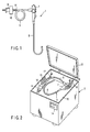
- FIG. 7 is an explanatory view that schematically shows the structure of an endoscope.
- FIG. 8 is an explanatory view that schematically shows the structure of an autoclave apparatus for sterilizing the endoscope shown in FIG. 7 .
- FIG. 9 is a time chart of an autoclave sterilization process using the autoclave apparatus shown in FIG. 8 .
- FIG. 10 is a flow chart that illustrates the autoclave sterilization process by the autoclave apparatus shown in FIG. 8 .
- an endoscope apparatus 101 includes an endoscope 102 with imaging means; a light source device 103 that is detachably connected to the endoscope 102 and supplies illumination light to a light guide (not shown) that is provided on the endoscope 102; a video processor 105 that is connected to the endoscope 102 via a signal cable 104, controls the imaging means of the endoscope 102, and processes a video signal obtained by the imaging means; and a monitor 106 that displays a video image corresponding to a subject image, which is output from the video processor 105.
- the endoscope 102 is formed such that the endoscope 102 can be subjected to a cleaning process after it is used for observation or treatment, and the endoscope 102, which has been subjected to the cleaning process, can subsequently be subjected to a sterilizing process using high-pressure steam.
- the endoscope 102 includes a flexible thin, long insertion section 107; an operation section 108 that is connected to a proximal end side of the insertion section 107; a flexible connection cord 109 that extends from a side part of the operation section 108; and a connection section 110 that is provided at an extension end of the connection cord 109 and is detachably connected to the light source device 103.
- a side part of the connector section 110 is provided with an electric connector section 111 that is detachably connectable to the signal cable 104 connected to the video processor 105.
- the electric connector section 111 is provided with an air passage portion (not shown) for communication between the inside of the endoscope 102 and the outside.
- connection part between the insertion section 107 and the operation section 108 is provided with an insertion-section-side breakage-preventing member 112 that has an elastic member for preventing sharp bending of the connection part.
- a connection part between the operation section 108 and connection cord 109 is provided with an operation-section-side breakage-preventing member 113.
- a connector-section-side breakage-preventing member 114 is provided at a connection part between the connection cord 109 and connection section 110.
- the insertion section 107 comprises a soft, flexible tube portion 115; a bendable portion 116 that is provided at a distal end side of the flexible tube portion 115 and can be bent by the operation of the operation section 108; and a distal end portion 117 that is provided at a distal end of the flexible tube portion 115 and is provided with an observation optical system and an illumination optical system (not shown).
- the distal end portion 117 of the insertion section 107 is provided with an air-feeding/water-feeding nozzle 118 for feeding a detergent or gas toward an optical member that is provided on the outer surface of the observation optical system (not shown) by an air-feeding operation and a water-feeding operation; a suction portion 119 that is a distal-end-side opening of an instrument channel (not shown) for insertion of an instrument provided in the insertion section 107 or for suction of liquid in a body cavity; and a liquid-feeding port 120 that is open to an object of observation and feeds liquid.
- the connector section 110 is provided with a gas-feeding mouthpiece 121 that is detachably connected to a gas supply source (not shown) that is built in the light source device 103; a water-feeding tank pressurizing mouthpiece 123 and a liquid supply mouthpiece 124, which are detachably connected to a water-feeding tank 122 that is a liquid supply source; a suction mouthpiece 125 that is connected to a suction source (not shown) for effecting suction from the suction port 119; and an injection mouthpiece 126 that is connected to water-feeding means (not shown) for feeding water from the liquid-feeding port 120.
- the connector section 110 is provided with a ground terminal mouthpiece 127 for feeding leak current back to a high-frequency treatment device when high-frequency leak current occurs in the endoscope in the case of conducting high-frequency treatment, etc.
- the operation section 108 is provided with an air-feed/water-feed operation button 128 for executing an air-feed operation and a water-feed operation; a suction operation button 129 for executing a suction operation; a bending operation knob 130 for executing a bending operation of the bendable portion; a plurality of remote switches 131 for remote-controlling the video processor 105; and an instrument insertion port 132 that is an opening communicating with the instrument channel.
- a watertight cap 133 with a pressure adjusting valve is detachably connectable to the electric connector section 111 of the endoscope 102.
- the watertight cap 133 is equipped with a pressure adjusting valve 133a.
- a sterilization case 134 for storing the endoscope 102 is used.
- the sterilization case 134 as shown in FIG. 7 , comprises a tray 135 and a cover member 136.
- the tray 135 and cover member 136 are provided with a plurality of air passage holes (not shown). Steam can pass through the air passage holes.
- the connector section 110 is provided with a restriction member (not shown) that corresponds to the shape of the endoscope 102.
- the restriction member is formed such that the respective parts of the endoscope 102 are placed at predetermined positions.
- the restriction member is provided with an insertion section restriction portion (not shown) in which the elongated flexible section 107 is stored.
- Typical conditions for high-pressure steam sterilization are U.S. standards ANSI/AAMI ST37-1992, which are endorsed by American National Standards Institute and issued by Association for the Advancement of Medical Instrumentation. According to these standards, in the case of the pre-vacuum type, the time for a sterilization step is four minutes at 132°C. In the case of the gravity type, the time for a sterilization step is 10 minutes at 132°C.
- the temperature condition for the sterilization step with high-pressure steam is generally set in the range of about 115°C to 138°C, although the temperatures vary depending on the type of the high-pressure steam sterilizing apparatus and the time of the sterilization step. In some types of sterilizing apparatuses, the temperature can be set at about 142°C.
- the time condition varies depending on the temperature condition for the sterilization step. In general, the time is set between about 3 minutes and 60 minutes. In some types of sterilizing apparatuses, the time can be set at about 100 minutes. In this step, the pressure in the sterilization chamber is generally set at about +0.2 MPa, relative to the atmospheric pressure.
- the high-pressure steam sterilization step for the general pre-vacuum type includes a pre-vacuum step for setting the sterilization chamber, where the to-be-sterilized apparatus is accommodated, in a vacuum state prior to sterilization, and a subsequent sterilization step for feeding high-pressure, high-temperature steam into the sterilization chamber and executing sterilization.
- the pre-vacuum step is a step for making the steam reach minute portions of the to-be-sterilized apparatus in the subsequent sterilization step.
- the pressure in the sterilization chamber is reduced so that high-pressure, high-temperature steam may reach every part of the to-be-sterilized apparatus.
- the pressure in the sterilization chamber in the pre-vacuum step is generally set at about -0.07 MPa to -0.09 MPa, relative to the atmospheric pressure.
- the sterilization step is followed by a drying step for setting the inside of the sterilization chamber in a reduced-pressure state once again, thereby to dry the sterilized apparatus.
- the sterilization chamber is decompressed to remove steam from the sterilization chamber. This facilitates the drying of the to-be-sterilized apparatus in the sterilization chamber.
- the pressure in the drying sterilization chamber in the drying step is generally set at about -0.07 MPa to -0.09 MPa, relative to the atmospheric pressure.
- the sterilization is performed in the state in which the watertight cap 133 with the pressure adjusting valve is attached to the electric connector section 111.
- the pressure adjusting valve 133a of the watertight cap 133 is closed, and the passage hole is closed by the watertight cap 133.
- the inside of the endoscope 102 is watertightly sealed from the outside.
- the pressure in the sterilization chamber is reduced in the pre-vacuum step, and such a pressure difference occurs that the outside pressure becomes lower than the inside pressure of the endoscope 102.
- the pressure adjusting valve 133a is opened and the inside and outside of the endoscope 102 communicate via the air passage hole. This prevents the occurrence of a large pressure difference between the inside of the endoscope 102 and the inside of the sterilization chamber. Hence, when the endoscope is subjected to the sterilizing process, no damage occurs due to the pressure difference between the inside and outside.
- the pressure adjusting valve 133a is closed.
- high-pressure, high-temperature steam does not positively enter the endoscope 102 via the watertight cap 133 and air passage hole.
- high-temperature, high-pressure steam gradually enters the endoscope 102 through, for example, the outer sheath of the flexible tube formed of high-polymer material or an O-ring formed of fluoro-rubber, silicone rubber, etc., which is a sealing means provided at a connection part of the outer member of the endoscope 102.
- a pressure acting from outside toward inside which is a sum of the reduced pressure in the pre-vacuum step and the applied pressure in the sterilization step, is applied to the outer member of the endoscope 102.
- a pressure acting inward from outside which corresponds to the reduced pressure in the pressure-reducing step, is applied to the outer member of the endoscope 102. If the watertight cap 133 is removed from the electric connector section 111, the inside and outside of the endoscope 102 communicate through the air passage hole and the inside pressure of the endoscope 102 changes to the atmospheric pressure. As a result, the pressure load on the outer member of the endoscope 102 is eliminated.
- a chamber 141 for accommodating the endoscope 102 and executing an autoclave process is formed in an autoclave apparatus 140.
- the autoclave apparatus 140 includes a water tank, a steam generating device and a suction pump, which are not shown.
- the autoclave apparatus 140 includes a process step selection section 142, a process step display section 143, an endoscope data reading device 144, and an endoscope data display section 145.
- the autoclave apparatus 140 also includes a write control section 125 that executes a control to write an executed treatment process condition, as history information, in the memory section of the endoscope 102; a step condition calculation section 126 that calculates a sterilization process condition relating to the step; and a control section 128.
- the control section 128 controls the sterilization step of the autoclave apparatus 140 in accordance with the sterilization process condition that is set by the step condition calculation section 126.
- the process step selection section 142 is provided with a plurality of operation buttons of A, B and C. Needless to say, the number of buttons may be four or more, or two.
- the endoscope data reading device 144 shown in FIG. 8 is detachably connectable to the electric connector section 111 of the endoscope 102.
- the endoscope data reading device 144 is connected to the autoclave apparatus 140 by means of a soft communication cord 144a.
- the connector section 110 incorporates a memory unit 146 that stores endoscope data. If the endoscope data reading device 144 is connected to the electric connector section 111, the autoclave apparatus 140 is enabled to read the data stored in the memory unit 146.
- the endoscope data reading device 144 can write executed process content, as history information, in the memory unit 146 of the to-be-processed endoscope 102.
- the endoscope data reading device 144 functions both as an apparatus for reading data and as an apparatus for writing data.
- Data may be written to and read from the memory unit 146 of the autoclave apparatus 140 by means of data transmission/reception using a non-electric-contact communication method, without using the apparatus 144 with the soft cord 144a.
- RFID radio frequency identification
- Examples of the RFID include “electromagnetic coupling method”, “capacitive coupling method”, “electromagnetic induction method”, “microwave method” and “optical communication method.” This method is applicable not only to data transmission/reception but also to power transmission/reception.
- FIG. 9 illustrates, in a simplified fashion, the autoclave sterilization step that is executed by the autoclave apparatus 140.
- a single autoclave sterilization process comprises a pre-vacuum step (PV step) for setting the inside of the chamber 141 in a negative-pressure state, a high-pressure steam sterilization step (S step) and a negative-pressure drying step (D step).
- PV step pre-vacuum step
- S step high-pressure steam sterilization step
- D step negative-pressure drying step
- a negative pressure is built, following which steam is injected. Thereby, steam can be sufficiently fed to thin channels in the endoscope 102.
- the inside of the endoscope 102 tries to have a higher pressure than the inside of the chamber 141.
- the pressure in the endoscope 102 is kept at a level close to the pressure in the chamber 141 by the function of the pressure adjusting valve 33a of the watertight cap 133.
- the temperature reaches a sterilization temperature of, e.g. 135°C.
- a small amount of steam enters the endoscope 102 via the soft flexible tube portion 115 or soft sealing portions at some locations (the outside pressure (i.e. pressure in the chamber 141) is much higher than the inside pressure of the endoscope 102).
- the inside of the chamber 141 is dried with hot air while the inside of the chamber 141 is kept at a negative pressure.
- the pressure adjusting valve 133a functions and most of the steam, which has entered the endoscope 102 in the S step, can be removed.
- FIG. 10 illustrates process steps relating to the handling of the data stored in the memory unit 146 of the endoscope 102. The flow of the process, as well as these steps, is described.
- step S1 of "read characteristic data of the endoscope” the watertight cap 133 of the cleaned endoscope 102 is once removed, and the endoscope data reading device 144 is connected to the electric connector section 111. Then, the autoclave apparatus 140 reads the information that is stored in the memory unit 146 of the endoscope 102.
- the information includes history information relating to, e.g. the PV step time and negative-pressure level, the S step time and temperature, and D step time and negative-pressure level in the previously executed autoclave processes.
- the history information which relates to, e.g. previous ten steps, may be displayed on the endoscope data display section 145.
- the information that is stored in the memory unit 146 may include information such as the model type of the endoscope 102, other than the history information.
- step S2 of "calculate a recommendable autoclave step” the autoclave apparatus 140 calculates, based on the read data, a recommendable step as an autoclave step that is next executed. For example, if it is determined that the previous D step time was shorter than a proper time, a step in which the D step time is relatively long is recommended.
- step S3 of "display a recommendable step” the content of the recommendable step is displayed on the process step display section 143, thus informing the user.
- the endoscope 102 is placed in the chamber 141. Prior to this, the watertight cap 133 is attached to the electric connector section 111.
- buttons on the process step selection section 142 designate three autoclave step patterns A, B and C.
- pattern A is most suitable to the endoscope 102, but the D step time is long.
- Pattern B is usable when a relatively quick process is required, and thus the D step time is relatively short.
- Pattern C relates to a process of autoclaving an instrument such as an accessory, a cleaning instrument or a treatment instrument, which has a simpler structure than the endoscope 102.
- both the PV step time and D step time are very short. That is, all the steps of the autoclave process can be completed in a very short time period.
- Pattern C is applicable to the endoscope 102 when a quick process is particularly required.
- the D step time is very short, the application of pattern C to the endoscope 102 leads to accumulation of moisture in the endoscope 102, degrading the durability of the endoscope 102.
- step S4 of "user setting/input” if pattern A was previously applied to the endoscope 102 in succession, the process step display section 143 displays a message to the effect that any one of patterns A to C is applicable. If a quick process is needed, the user can select pattern C.
- the autoclave apparatus 140 that reads the associated data causes the display section 143 to display a message to the effect that pattern A is recommendable.
- the autoclave apparatus 140 may be configured to become inoperable if the user presses buttons other than the button A.
- step S5 of "execute an autoclave step” is performed and the autoclave operation is started.
- step S6 of "write step result information in the endoscope” is executed.
- the endoscope 102 is taken out of the chamber 141, and the watertight cap 133 is removed from the electric connector section 111.
- the endoscope data reading device 144 is connected to the electric connector section 111 once again.
- the executed process content is written as history information in the memory unit 146 of the endoscope 102 that is the object of processing.
- the data relating to the autoclave process which is executed each time, is managed for each endoscope. Based on the data, an autoclave process that is next executed is determined. Thereby, the durability of the endoscope 102 is secured.
- the D step is an important step for minimizing the moisture in the endoscope 102. If the user desires a quick process and the D step time becomes inadequate, the durability of the endoscope 102 is seriously affected.
- this embodiment may adopt such management that the number of times and the frequency of execution of the process with the above-mentioned special condition are recorded, and the same endoscope is prevented from being subjected to the process many times.
- the patterns A, B and C of the autoclave process may be associated with displays that recommend applicable products such as “flexible endoscope”, “rigid endoscope” and “forceps”. Further, buttons, which are indicative of “flexible endoscope”, “rigid endoscope”, “forceps” and “linen”, may be provided. If the objects that are placed in the chamber 41 are a forceps and linen, the user may press the buttons indicative of "forceps" and "linen”. Then, the autoclave apparatus 40 executes calculations and determines a process that is suitable for autoclaving the two objects, and automatically operates.
- the user can select the autoclave process in accordance with the need at each time, and the durability of the endoscope can be secured.
- FIG. 11 is an explanatory view that shows the structure of the autoclave apparatus that subjects the endoscope to autoclave-sterilization.
- FIG. 12 is a flow chart illustrating the flow of the autoclave process using the autoclave apparatus shown in FIG. 11 .
- an autoclave apparatus 140 and an endoscope cleaning apparatus 147 are connected to a central management apparatus 148 by a signal line 149.
- the autoclave apparatus 140 itself does not execute data management and processing.
- the data management and processing are executed by the central management apparatus 148.
- a plurality of autoclave apparatuses 140 and a plurality of endoscope cleaning apparatuses 147 may be provided. In this case, too, the data management/processing is executed by the common central management apparatus 148.
- the present embodiment is the same as the second embodiment.
- step S11 the endoscope data reading device 144 is connected to the electric connector section 111 before the endoscope 102 is placed in the chamber 141.
- the central management apparatus 148 reads out the ID number of the endoscope from the memory unit 146.
- the central management apparatus 148 stores past records relating to the ID number.
- the central management apparatus 148 reads out the data that relates to, for instance, the PV step time and negative-pressure level, the S step time and temperature and the D step time and negative-pressure level in the previously executed autoclave step. Then, the central management apparatus 48 executes the process of "calculate a recommendable autoclave step" in step S13.
- step S14 information relating to a recommendable process is sent to the autoclave apparatus 140 and the process step display section 143 is caused to display the information, thereby notifying the user.
- step S15 the user sets (inputs) the process to be executed.
- one of the buttons on the process step selection section 142 is selected.
- the process step selection section 142 may be composed of a touch panel such that the user can freely input, e.g. the D step time in units of a minute. If the input content differs from the recommendable process content that is displayed on the process step display section 143, the central management apparatus 148 may execute determination and may effect alarm display on the process step display section 143. In addition, the central management apparatus 148 may control the autoclave apparatus 140 so as to prohibit the operation of the autoclave apparatus 140.
- step S16 the autoclave sterilization is executed. If the sterilization is completed, the information relating to the executed process is sent to the central management apparatus 148 in step S17 and is stored in the memory unit as the information associated with the ID number.
- Information of the temperature sensor and pressure sensor that are provided in the chamber 141 may be recorded as management information as to whether the autoclave apparatus 140 has normally operated in fact. If abnormality occurs, the central management apparatus 148 executes a control to suspend the process and to effect display on the process step display section 143 to prompt the user to perform a check.
- the chamber 141 may be provided with a sound sensor to sense burst sound.
- the endoscope 102 is cleaned by the endoscope cleaning apparatus 147 before executing autoclave sterilization.
- the endoscope cleaning apparatus 147 may also be provided with the endoscope data reading device 144 and the central management apparatus 148 may manage the information as to what kind of cleaning was done.
- the central management apparatus 148 may be connected to the video processor 105. If the user connects the signal cable 104 to the electric connector section 111 at the time of an inspection, it becomes possible to quickly and exactly understand whether the endoscope has normally been cleaned/sterilized.
- the common central management apparatus 148 can manage/control the plural endoscopes 102, endoscope cleaning apparatuses 147 and autoclave apparatuses 140. Therefore, the structure of the memory unit 146 can be made simpler, and the computers (information processing units, control units) in the autoclave apparatus 140 and endoscope cleaning apparatus 147 can be dispensed with. In particular, in a large-scale hospital, it becomes possible to comprehensively secure the exact information management and the durability of endoscopes at a minimum cost.
- an efficient system can be provided in the case where a plurality of autoclave apparatuses 140 are employed.
- FIG. 13 is an explanatory view that schematically shows the structure of an autoclave apparatus for autoclaving the endoscope 102 in the state in which the endoscope 102 is placed in the chamber 141.
- an endoscope connection section 150 which is provided on the autoclave apparatus 140 and is substituted for the above-described watertight cap 133, is connected to the electric connector section 111.
- a control unit 151 of the autoclave apparatus 140 is rendered communicable with the memory unit 146.
- the inside of the endoscope 102 communicates with a conduit 152.
- the conduit 152 communicates with the outside of the autoclave apparatus 140 via a control valve 153.
- a conduit 154 communicates with the chamber 141 and reaches a control valve 156 via a filter 155 that blocks passage of micro-organisms.
- the control valve 153 communicates with the control valve 156 via a conduit 157.
- the control unit 151 controls the control valve 153, control valve 156, suction pump 158 and the steam generating device (not shown).
- the present embodiment is the same as the second embodiment.
- the conduit connection section 150 is connected to the watertight cap 111. Thereby, like the second embodiment, information is read out of the memory unit 146 and the control unit 151 executes processing.
- a variation in pressure in the chamber 141 of the autoclave process is controlled in the following manner. For example, when the chamber 141 is set at a negative pressure by the suction pump 158, the control valve 153 equalizes the pressures in the endoscope 102 and to the pressure in the chamber 141. (That is, the inside of the endoscope 102 is also set at a negative pressure by the suction pump 158.)
- the control valve 153 is controlled to eliminate moisture in the endoscope 102 as quickly as possible.
- the inside of the endoscope 102 is sucked by the suction pump 158 and set at a negative pressure level.
- a suction device for sucking an inside gas in the endoscope 102 is constituted.
- air is let into the endoscope 102 from the outside of the autoclave apparatus 140.
- An injection device, which injects a gas different from the gas in the endoscope into the endoscope 102 after the suction, is thus constituted.
- gas in the chamber 141 is drawn. Using the same means described above, ventilation may be achieved.
- gas in the chamber 141 may be fed into the endoscope 102 from the endoscope connection section 150 via the control valve 156 and control valve 153 and the gas in the endoscope 102 may be replaced with the air in the chamber 141. Outside air is not necessarily in a high-level dry state. In this way, ventilation in a high-level dry state can be executed by feeding the gas in the chamber 141, which is in the high-level dry state, into the endoscope 102.
- a cooling device may be provided at a given position on the conduit 152, and cool gas may be fed into the endoscope 102 to more quickly cool the endoscope 102.
- Ventction in the endoscope 102 can be executed using the suction pump 158 that is employed to control the pressure in the chamber 141. Therefore, there is no need to provide another pump for ventilation in the endoscope 102, and the cost is reduced.
- the suction pump 158 may be provided anywhere along the flow path of the conduit 152, control valve 153, conduit 157, control valve 156 and conduit 154. Using the suction pump 158, air may be fed from the outside of the autoclave apparatus 140 into the chamber 141 via the filter 155, thereby cooling the endoscope 102. In this case, it is preferable that the cooling step be executed after the drying step for drying the inside of the chamber 141. This can reduce the cooling time, without condensation.
- the inside of the endoscope can easily be ventilated, and the durability can be secured.
- the autoclave apparatus 140 may integrally be provided with the function of cleaning the endoscope 102. Thereby, the characteristic information relating to the cleaning/sterilization of the endoscope 102 can be managed with a single setting.
Landscapes
- Health & Medical Sciences (AREA)
- Life Sciences & Earth Sciences (AREA)
- Veterinary Medicine (AREA)
- Public Health (AREA)
- General Health & Medical Sciences (AREA)
- Animal Behavior & Ethology (AREA)
- Surgery (AREA)
- Epidemiology (AREA)
- Optics & Photonics (AREA)
- Engineering & Computer Science (AREA)
- Biomedical Technology (AREA)
- Heart & Thoracic Surgery (AREA)
- Medical Informatics (AREA)
- Molecular Biology (AREA)
- Radiology & Medical Imaging (AREA)
- Pathology (AREA)
- Physics & Mathematics (AREA)
- Nuclear Medicine, Radiotherapy & Molecular Imaging (AREA)
- Biophysics (AREA)
- Endoscopes (AREA)
- Apparatus For Disinfection Or Sterilisation (AREA)
Description
- The present invention relates to a sterilizing apparatus and a sterilizing method for sterilizing a to-be-sterilized object such as an endoscope.
- After an endoscope is used in an inspection, the endoscope is cleaned by a cleaning apparatus to remove contamination on the endoscope. Subsequently, the endoscope is subjected to high-pressure steam in an autoclave apparatus, and the endoscope is sterilized to prevent infection. In this way, the cleaning and sterilization of the endoscope are independently performed by the different apparatuses.
- If contamination on the endoscope is not removed, steam for sterilization does not sufficiently come in contact with that part of the surface of the endoscope, where contamination is present, in a process of sterilizing the endoscope by means of a sterilizing apparatus. Consequently, the effect of sterilization cannot fully be obtained. Besides, if there is a hole or a flaw in the endoscope, electronic components that are built in the endoscope would be damaged by exposure to high-pressure steam. To prevent this, a leak check for checking the presence of a hole or a flaw needs to be executed before the endoscope is sterilized by the sterilizing apparatus.
- The endoscope should be sterilized by the sterilizing apparatus after the endoscope has exactly undergone the cleaning process and leak check. However, the user has to check whether the endoscope has undergone the cleaning process and leak check.
- In addition, the user manually inputs conditions for the sterilization process to the sterilizing apparatus. However, as will be described later, the work of exactly inputting information associated with the conditions of individual endoscopes is complex and time-consuming due to peculiar problems of endoscopes. The load on the user side is great, and the user is required to have relatively high-level expertise.
- Endoscopes have various structures depending on their types. There are endoscopes with complex channel structures, endoscopes with large channel lengths, and endoscopes with very thin channels. Such endoscopes require a considerable length of time for a sterilizing process until steam for sterilization reaches all parts of the channels.
- In the case of an endoscope having no channels or a short, thick endoscope with a simple channel structure, steam can reach all parts of channels in a short time period and a process time may be short. In addition, in the case of an endoscope with resistance to high temperatures and high pressures, the sterilization process time for the endoscope can be reduced by raising the set values of the temperature and pressure for the sterilizing process.
- On the other hand, in the high-pressure steam sterilization process, the endoscope that is to be sterilized is placed in a process chamber and exposed to high-temperature steam. Immediately after sterilization, the body of the endoscope has a high temperature due to remaining heat. Electronic components that are built in the body of the endoscope, in particular, an imaging component such as a CCD (Charge-Coupled Device), are affected by the heat at the time of sterilization and their functions are degraded. Noise, etc. may be included in an image, and the quality of the image may deteriorate. In order to use the endoscope successively, it is necessary to wait until the endoscope is completely cooled.
- In a step of disinfecting/sterilizing the endoscope using an autoclave apparatus, a high-pressure/high-humidity atmosphere is created in the process chamber. In addition, in order to facilitate flow of steam into the process chamber, the process chamber is evacuated prior to starting the process.
- In the case where the endoscope is disinfected/sterilized by the autoclave apparatus, the user can change the settings relating to the process to be executed. For example, an autoclave apparatus, which is disclosed in Jpn. Pat. Appln. KOKAI Publication No.
5-285103 - The above-mentioned prior art document relating to the autoclave apparatus describes that the durability of the endoscope is secured by adjusting the pressure in the chamber and the pressure in the endoscope. This document, however, does not describe the relation between the variations of the process and the durability of the endoscope. Nor does the document mention the control of the dry state of the inside gas in the endoscope. The dry state of the inside of the endoscope, which has been autoclaved, is closely related to the durability of the endoscope. If much moisture remains in the endoscope, the durability of the endoscope tends to decrease. However, the addition of an excessive drying step leads to an increase in process time and is disadvantageous when a quick process is needed. Besides, if proper conditions for sterilization can be set depending on the condition in which the endoscope was used or the state of contamination, degradation in the endoscope can be prevented.
- Document
US 4,862,872 A discloses to store in a memory section of an endoscope patient data which reflects the usage of the endoscope with regard to the patient in the past. Cleaning/sterilizing processes of the endoscope are controlled in dependence on the stored patient data. - The present invention has been made in consideration of the above problems. An object of the invention is to provide a sterilizing apparatus that can reduce a load on a user, and can exactly and quickly execute a sterilizing process under a proper sterilization process condition.
- Another object of the invention is to provide a sterilizing apparatus that can prevent degradation in an endoscope due to variations in a sterilizing process using an autoclave.
- The present invention provides a sterilizing apparatus according to
claim 1. - According to the invention, cleaning information and sterilization information is stored in a to-be-sterilized object such as an endoscope. Based on the information, the process is automatically confirmed and corrected. Therefore, the invention can provide a sterilizing apparatus that can reduce a load on a user, and can exactly and quickly execute a process.
- The invention also provides a sterilizing method according to
claim 11. - In the invention, information relating to the type, history, etc. of a to-be-sterilized object is stored. Based on the information, the process condition is automatically set and confirmed, and correction is made to the to-be-sterilized object. According to the invention, it is possible to prevent degradation in an endoscope due to variations in a sterilizing process.
-
-
FIG. 1 is a side view that schematically shows the entirety of an endoscope according to a first embodiment; -
FIG. 2 is a perspective view of an endoscope cleaning apparatus according to the first embodiment; -
FIG. 3 is a perspective view of an endoscope sterilizing apparatus according to the first embodiment; -
FIG. 4 is a perspective view of the entirety of an endoscopy system according to the first embodiment; -
FIG. 5 is a block diagram of the endoscopy system according to the first embodiment; -
FIG. 6 is a circuit diagram of an RFID unit and an RFID tag of the endoscopy system according to the first embodiment; -
FIG. 7 shows the structure of an endoscope apparatus according to a second embodiment; -
FIG. 8 is a perspective view that shows the structure of an autoclave apparatus according to the second embodiment; -
FIG. 9 is a time chart that illustrates an autoclave process using the autoclave apparatus shown inFIG. 8 ; -
FIG. 10 is a flow chart that illustrates the autoclave process using the autoclave apparatus shown inFIG. 8 ; -
FIG. 11 shows the structure of an autoclave apparatus according to a third embodiment; -
FIG. 12 is a flow chart that illustrates an autoclave process using the autoclave apparatus shown inFIG. 11 ; and -
FIG. 13 schematically shows the structure of an autoclave apparatus according to a fourth embodiment. - An endoscope cleaning apparatus according to a first embodiment of the invention will now be described with reference to
FIG. 1 to FIG. 6 .FIG. 1 schematically shows anendoscope 1.FIG. 2 shows anendoscope cleaning apparatus 2 for cleaning theendoscope 1.FIG. 3 shows anendoscope sterilizing apparatus 3 for sterilizing theendoscope 1.FIG. 4 schematically shows anendoscopy system 4.FIG. 5 is a block diagram of theendoscopy system 4, andFIG. 6 is a circuit diagram of an RFID unit and an RFID tag. - The
endoscope 1 includes aninsertion section 6, anoperation section 7 and alight guide cable 8. Aconnector 9 is provided at an extension end of thelight guide cable 8. Acommunication connector section 10 for electrical connection to a peripheral device (not shown) is provided in the vicinity of theconnector 9. Thecommunication connector section 10 is provided with a connector portion for leakage testing (not shown). Thecommunication connector 10 is equipped with a waterproof cap (not shown) that covers an exposed part of an electrical connection portion of thecommunication connector 10. When theendoscope 1 is cleaned and sterilized, the waterproof cap (not shown) prevents entrance of liquid such as a detergent or a disinfectant and protects theendoscope 1. - An
RFID tag 11 is provided at a position on thelight guide cable 8 near theconnector 9. TheRFID tag 11 executes data transmission/reception in a non-electrical-contact method with an RFID unit (to be described later) that is provided on another apparatus such as the endoscope video processor,endoscope cleaning apparatus 2 orendoscope sterilizing apparatus 3. TheRFID tag 11 includes a CPU (Central Processing Unit), a transmission/reception circuit, an antenna and a memory. - The basic principle of the non-electrical-contact method is a communication system using RFID (radio frequency identification) that uses radio waves. Examples of the RFID include "electromagnetic coupling method", "capacitive coupling method", "electromagnetic induction method", "microwave method" and "optical communication method." In general, RFID is applicable not only to data transmission/reception but also to power transmission/reception.
- The memory (characteristic information recording section) of the
RFID tag 11 stores characteristic information that includes history information as to whether the cleaning of theendoscope 1 that is to be sterilized is completed, as to when the cleaning process was executed, as to the result of leakage testing, as to whether sterilization is completed, and as to when sterilization was performed. In addition to the history information, the characteristic information includes information relating to the model name, i.e., type, of theendoscope 1, the product serial number of theendoscope 1, the time when an endoscopic inspection was conducted, and the case of treatment for which theendoscope 1 was used. - An RFID system (wireless automatic recognition system) is constituted by the
RFID tag 11 of theendoscope 1 and an RFID unit that is included in each of theendoscope video processor 32,endoscope cleaning apparatus 2 andendoscope sterilizing apparatus 3, which are described later. Information transmission/reception and power supply are executed through the communication using the RFID system. The RFID system adopts a wireless communication method using high-frequency waves, and not a wired method using electrical contact. Thus, both theRFID tag 11 and RFID unit can be sealed with members of a resin, etc., and both theRFID tag 11 and RFID unit have complete waterproof structures. - The
endoscope cleaning apparatus 2 shown inFIG. 2 comprises a cleaningbath 12 that accommodates theendoscope 1 as a medical instrument to be cleaned, atop cover 13, and acontrol panel 14 that sets sterilization process conditions such as a process step program. - The
RFID unit 15 is provided on a part of the cleaningbath 12. TheRFID unit 15 constitutes an information reading unit that executes communication with theRFID tag 11 of theendoscope 1 that is accommodated in the cleaningbath 12, and reads record information in theRFID tag 11 that stores information such as the model name, product serial number, history, etc. of theendoscope 1. - The
endoscope cleaning apparatus 2 includes cleaning process condition setting means (step condition calculating section) that sets process conditions for cleaning theendoscope 1 accommodated in the cleaningbath 12, on the basis of the information of theendoscope 1 that is read out of theendoscope 1 accommodated in the cleaningbath 12. TheRFID unit 15 is composed of a transmission/reception circuit, an antenna, etc., and is controlled by a control unit that is built in theendoscope cleaning apparatus 2. - When the
endoscope 1 is cleaned by theendoscope cleaning apparatus 2, theendoscope 1 is set in the cleaningbath 12, as shown inFIG. 2 . Endoscopechannel cleaning tubes 16 are connected to theendoscope 1 in order to clean the channels in theendoscope 1. A detergent is fed into the channels of theendoscope 1 through thecleaning tubes 16 from theendoscope cleaning apparatus 2 side. Thereby, the inside of each channel of the endoscope can be cleaned. - A
leak test tube 17 is connected to the connector portion for leakage testing in order to perform a leak test step for confirming that the outer member of theendoscope 1 has no hole or flaw. When theleak test tube 17 is connected to theendoscope 1, theleak test tube 17 communicates with the inside of theendoscope 1. Then, a leak test step is started. Air is fed into theendoscope 1 through theleak test tube 17 from theendoscope cleaning apparatus 2. An air feed pressure at this time is measured by a leak sensor. If there is no hole or flaw in theendoscope 1, the air that is fed into theendoscope 1 does not leak, and a predetermined pressure value is indicated. If leakage occurs, the pressure value decreases and a leak portion of theendoscope 1 is detected. In this manner, it can be confirmed whether there is a hole or flaw in theendoscope 1. - As is shown in
FIG. 3 , theendoscope sterilizing apparatus 3 includes a chamber (containing section) 21 for accommodating theendoscope 1 to be sterilized. AnRFID unit 22 is provided on a part of thechamber 21. Like the above-describedRFID unit 22 of theendoscope cleaning apparatus 2, theRFID unit 22 is composed of a transmission/reception circuit, an antenna, etc. TheRFID unit 22 is controlled by a control unit in theendoscope sterilizing apparatus 3. TheRFID unit 22 executes wireless communication with theRFID tag 11 of theendoscope 1 and constitutes communication means for reading record information of theRFID tag 11 that stores information such as the model name, product serial number, history, etc. of theendoscope 1 accommodated in thechamber 21. In addition, theRFID unit 22 constitutes sterilization process condition setting means for setting process conditions for sterilizing the endoscope I accommodated in thechamber 21, on the basis of the characteristic information of theendoscope 1 that is read out of theendoscope 1 accommodated in thechamber 21 of theendoscope sterilizing apparatus 3. - A
cover 23 is provided on the inlet of thechamber 21. Acontrol panel 24 is provided on the front surface of theendoscope sterilizing apparatus 3. Sterilization process conditions can be set through thecontrol panel 24. -
FIG. 4 schematically shows theendoscopy system 4. Theendoscopy system 4 includes alight source device 31, avideo processor 32 and amonitor 33. Thevideo processor 32 is provided with anRFID unit 34. TheRFID unit 34 is controlled by a control unit that is provided in thevideo processor 32. TheRFID unit 34 executes wireless communication with theRFID tag 11 of theendoscope 1. -
FIG. 5 is a block diagram of theendoscopy system 4. Theendoscope 1 includes aCCD 41, acontrol unit 42 and amemory 43. In addition, theendoscope 1 includes the above-describedRFID tag 11. Thevideo processor 32 for the endoscope includes animage processing unit 44, acontrol unit 45 and amemory 46. In addition, thevideo processor 32 includes the above-describedRFID unit 34. - At a time of endoscopy, a video signal that is obtained by the
CCD 41 of theendoscope 1 is sent to theimage processing unit 44 of thevideo processor 32. The video signal is converted to an image signal by theimage processing unit 44. The image signal is sent to themonitor 33, and themonitor 33 that serves as indication means displays an image. Wireless communication is executed by the RFID system between theendoscope 1 andvideo processor 32. - Wireless communication is executed between the
RFID tag 11 ofendoscope 1 and theRFID unit 34. Prior to endoscopy, the cleaning information and sterilization information of theendoscope 1 and the characteristic information of the model number, etc. of theendoscope 1 are read in from theRFID tag 11. After the endoscopy, the information relating to the content of endoscopy, etc. is written in theRFID tag 11. -
FIG. 6 shows circuit configurations of theRFID unit RFID tag 11. TheRFID units cleaning apparatus 2, sterilizingapparatus 3 andvideo processor 32, respectively. - Each of the
RFID unit controller 54. The transmission unit includes amodulation circuit 52 having anoscillation circuit 51 for transmission, and a transmission coil L1. The receiving unit that includes a receiving coil L2 and ademodulation circuit 53. Thecontroller 54 controls the transmission/reception by these units. Thecontroller 54 is connected to a main-body control circuit 50 that is provided in the apparatus main body. - The
RFID tag 11 of theendoscope 1 comprises a coil L3 for signal transmission/reception, a capacitor C for oscillation, ademodulation circuit 55, aconverter 56, amodulator 57, amain control unit 58 for controlling the respective components, and amemory 59. TheRFID tag 11 includes apower supply circuit 60 that smoothes/rectifies a signal, which is received by a coil L4, and produces a stabilized drive power. The respective components are driven by the power produced by thepower supply circuit 60. - Next, the operation of the present embodiment is described. To begin with, when the
endoscope 1 is to be subjected to a cleaning process, theendoscope 1 is set in theendoscope cleaning apparatus 2, and a leak test process is executed to confirm whether there is a hole or a flaw in theendoscope 1. If a flaw in theendoscope 1 is detected in the test, an alarm is issued to the user and the user is prompted to immediately repair theendoscope 1. It is better to also perform a channel clogging detection step for confirming whether the endoscope channel is clogged. - The cleaning process for the
endoscope 1 is started after confirming that there is no flaw in theendoscope 1 and no problem would arise even if theendoscope 1 is immersed in washing water. - After the cleaning process for the
endoscope 1 is finished, theendoscope cleaning apparatus 2 activates theRFID unit 15 and executes communication with theRFID tag 11 of theendoscope 1. Cleaning information as to when the cleaning of theendoscope 1 was performed and as to the result of the leak test step is written in theRFID tag 11 of theendoscope 1. Specifically, in theRFID unit 15, the coil L1 is supplied with a radio-frequency wireless signal that is digitally modulated according to a write command, which is transferred as a serial signal from thecontroller 54 under the control of the main-body control circuit 50 of theendoscope cleaning apparatus 2. In theRFID tag 11 in theendoscope 1, the coil L3 receives the wireless signal that is sent from the coil L1 of theRFID unit 15. A signal that is induced by the wireless signal is amplified and demodulated into the original digital signal in thedemodulation circuit 55. Based on the digital serial signal information, themain control unit 58 writes information in thememory 59. In this way, communication is executed between theRFID tag 11 andRFID unit 15, and information is stored in thememory 59 in theRFID tag 11 of theendoscope 1. - After the
endoscope 1 is cleaned, theendoscope 1 is set in thechamber 21 of the sterilizingapparatus 3, and the sterilizing process for theendoscope 1 is executed. When the sterilizing process operation is started, the sterilizingapparatus 3 communicates with theendoscope 1 and confirms the cleaning information and the model number of theendoscope 1, which is stored in theRFID tag 11 of theendoscope 1. Specifically, in theRFID unit 22, the coil L1 is supplied with a radio-frequency wireless signal that is digitally modulated according to a read command, which is transferred as a serial signal from thecontroller 54 under the control of the main-body control circuit 50 of the sterilizingapparatus 3. In theRFID tag 11 in theendoscope 1, a signal that is induced in the coil L3 is amplified and demodulated into the original digital signal in thedemodulation circuit 55. Based on the digital serial signal information, themain control unit 58 of theRFID tag 11 reads in data from thememory 59, and converts the data to a serial signal in sync with a non-modulated signal sent from the coil L1. According to this signal, themodulation circuit 57 executes a control as to whether a tank circuit of the coil L3 and capacitor C is set in a resonant state. - The
controller 54 in theRFID unit 22 detects, through the coil L2, whether the tank circuit in theRFID tag 11 resonates. Thereby, communication of information is executed. In this way, communication is executed between theRFID tag 11 andRFID unit 22, and information is read out of thememory 59 in theRFID tag 11 of theendoscope 1. - If the obtained information indicates that the
endoscope 1 has not been cleaned or the result of the leak test step shows the possibility of a flaw in theendoscope 1, the sterilizingapparatus 3 does not start the sterilizing process operation and issues an alarm to the user to confirm these matters. - If it is determined that the sterilizing process is executable on the basis of the information stored in the
memory 59 in theRFID tag 11 of theendoscope 1, the sterilizing process operation is started. The contents of the sterilization process conditions are automatically set on the basis of the information of the model number, etc. of theendoscope 1. For example, in the case of a long endoscope for colonoscopy or an endoscope with a very thin channel such as a forceps-raising wire guide, a long time is needed until steam for sterilization reaches all parts of the channel. Thus, the process time is set to be long. On the other hand, in the case of an endoscope with a simple channel structure or an endoscope with a short channel, the process time is set to be short. In the case of an endoscope of the type that is resistant to higher sterilization steam temperatures or higher pressures than normal levels, the sterilization steam temperature and pressure are increased and the process time is set to be short. The sterilizing process conditions can also be set in accordance with the information relating to the history of use of theendoscope 1 or the history of cleaning/sterilization. Thus, the sterilizing process is executed on the basis of the content of the sterilizing process that is properly set according to theendoscope 1 to be sterilized. - If the sterilizing process for the
endoscope 1 is completed, the sterilizingapparatus 3 executes communication with theendoscope 1 once again and stores sterilization information, which relates to the time and kind of the sterilizing process, into thememory 59 in theRFID tag 11 of theendoscope 1. - Subsequently, when an inspection is to be conducted using the sterilized
endoscope 1, theendoscope 1 is connected to thelight source device 31 andvideo processor 32, as shown inFIG. 4 . Thevideo processor 32 communicates with theconnected endoscope 1 and confirms the sterilization information. If it is confirmed that theendoscope 1 is a sterilized one, the sterilization information as to what kind of sterilizing process was executed and when it was done is displayed on themonitor 33, and the user is prompted to confirm the information. If it is determined that theendoscope 1 is not a sterilized one, themonitor 33 displays a corresponding alarm message to the user. - The
video processor 32 confirms the sterilizing process content and estimates the temperature of theCCD 41 of theendoscope 1. Thevideo processor 32 prestores data relating to a temperature decrease of theCCD 41 of theendoscope 1 in the case where theendoscope 1 is sterilized and then left in the natural state. By communication with theendoscope 1, thevideo processor 32 recognizes an elapsed time from the completion of the sterilizing process and thus calculates the temperature of theCCD 41. When an endoscopic image that is taken by theCCD 41 is subjected to image processing, a filtration constant for removing noise due to the heat of theCCD 41 is calculated on the basis of the temperature of theCCD 41. Thereby, correction of the endoscopic image is automatically executed. Thus, theendoscope 1 can continuously be used without waiting for a long time until theCCD 41 in theendoscope 1 is completely cooled down. - As has been described above, in the present embodiment, the video processor, cleaning apparatus and sterilizing apparatus for the endoscope are configured to be able to write, by communication, the cleaning information and sterilization information in the memory in the endoscope, and to read out information from the memory. Based on the information, the process conditions are automatically set or corrected. Thereby, the load on a user is reduced, and the exact and quick process can be executed.
- When the endoscope is subjected to the cleaning process in the cleaning apparatus, the cleaning apparatus communicates with the endoscope and receives information relating to the endoscope. In addition, the cleaning apparatus stores information relating to the cleaning in the memory means of the
endoscope 1. The information relating to the cleaning, in this context, refers to, for instance, information as to when the cleaning process was executed, information as to what kind of cleaning process was executed, information relating to the result of a leak test step for confirming whether leakage occurs in the endoscope, and information relating to the result of a channel clogging detection step for confirming whether the endoscope channel is clogged. - When the endoscope is subjected to the sterilizing process in the sterilizing apparatus, the endoscope sterilizing apparatus communicates with the endoscope and acquires information relating to the cleaning and information relating to the endoscope itself, which are stored in the endoscope. Based on the information, the endoscope sterilizing apparatus confirms whether the
endoscope 1 has exactly been cleaned. In addition, the endoscope sterilizing apparatus confirms whether the endoscope is free from leakage or channel clogging. If it is not possible to confirm such information, an alarm may be issued to the user to prevent the sterilizing process from being started. - On the other hand, the conditions for the sterilizing process are automatically set in accordance with the type of the endoscope. When the sterilizing process is completed, the
endoscope sterilizing apparatus 3 executes communication with theendoscope 1 once again and stores the information relating to sterilization in the endoscope. The information relating to sterilization, in this context, refers to, for instance, information as to what kind of sterilizing process was executed and when the sterilizing process as executed. - When endoscopy is conducted using the sterilized endoscope, the endoscope image processing apparatus communicates with the endoscope and acquires information relating to the sterilization. Based on the information as to what kind of sterilizing process was executed and when the sterilizing process as executed, the endoscope image processing apparatus estimates the temperature in the inside of the endoscope and executes, for example, a noise-reduction image process in accordance with the temperature characteristics of the CCD.
- An autoclave apparatus according to a second embodiment of the invention will now be described with reference to
FIG. 7 to FIG. 10 .FIG. 7 is an explanatory view that schematically shows the structure of an endoscope.FIG. 8 is an explanatory view that schematically shows the structure of an autoclave apparatus for sterilizing the endoscope shown inFIG. 7 .FIG. 9 is a time chart of an autoclave sterilization process using the autoclave apparatus shown inFIG. 8 .FIG. 10 is a flow chart that illustrates the autoclave sterilization process by the autoclave apparatus shown inFIG. 8 . - As is shown in
FIG. 7 , anendoscope apparatus 101 includes anendoscope 102 with imaging means; alight source device 103 that is detachably connected to theendoscope 102 and supplies illumination light to a light guide (not shown) that is provided on theendoscope 102; avideo processor 105 that is connected to theendoscope 102 via asignal cable 104, controls the imaging means of theendoscope 102, and processes a video signal obtained by the imaging means; and amonitor 106 that displays a video image corresponding to a subject image, which is output from thevideo processor 105. - The
endoscope 102 is formed such that theendoscope 102 can be subjected to a cleaning process after it is used for observation or treatment, and theendoscope 102, which has been subjected to the cleaning process, can subsequently be subjected to a sterilizing process using high-pressure steam. Theendoscope 102 includes a flexible thin,long insertion section 107; anoperation section 108 that is connected to a proximal end side of theinsertion section 107; aflexible connection cord 109 that extends from a side part of theoperation section 108; and aconnection section 110 that is provided at an extension end of theconnection cord 109 and is detachably connected to thelight source device 103. A side part of theconnector section 110 is provided with anelectric connector section 111 that is detachably connectable to thesignal cable 104 connected to thevideo processor 105. Theelectric connector section 111 is provided with an air passage portion (not shown) for communication between the inside of theendoscope 102 and the outside. - A connection part between the
insertion section 107 and theoperation section 108 is provided with an insertion-section-side breakage-preventingmember 112 that has an elastic member for preventing sharp bending of the connection part. Similarly, a connection part between theoperation section 108 andconnection cord 109 is provided with an operation-section-side breakage-preventingmember 113. In addition, a connector-section-side breakage-preventingmember 114 is provided at a connection part between theconnection cord 109 andconnection section 110. - The
insertion section 107 comprises a soft,flexible tube portion 115; abendable portion 116 that is provided at a distal end side of theflexible tube portion 115 and can be bent by the operation of theoperation section 108; and adistal end portion 117 that is provided at a distal end of theflexible tube portion 115 and is provided with an observation optical system and an illumination optical system (not shown). - The
distal end portion 117 of theinsertion section 107 is provided with an air-feeding/water-feedingnozzle 118 for feeding a detergent or gas toward an optical member that is provided on the outer surface of the observation optical system (not shown) by an air-feeding operation and a water-feeding operation; asuction portion 119 that is a distal-end-side opening of an instrument channel (not shown) for insertion of an instrument provided in theinsertion section 107 or for suction of liquid in a body cavity; and a liquid-feedingport 120 that is open to an object of observation and feeds liquid. - As is shown in
FIG. 7 , theconnector section 110 is provided with a gas-feedingmouthpiece 121 that is detachably connected to a gas supply source (not shown) that is built in thelight source device 103; a water-feedingtank pressurizing mouthpiece 123 and aliquid supply mouthpiece 124, which are detachably connected to a water-feeding tank 122 that is a liquid supply source; asuction mouthpiece 125 that is connected to a suction source (not shown) for effecting suction from thesuction port 119; and aninjection mouthpiece 126 that is connected to water-feeding means (not shown) for feeding water from the liquid-feedingport 120. Theconnector section 110 is provided with aground terminal mouthpiece 127 for feeding leak current back to a high-frequency treatment device when high-frequency leak current occurs in the endoscope in the case of conducting high-frequency treatment, etc. - The
operation section 108 is provided with an air-feed/water-feed operation button 128 for executing an air-feed operation and a water-feed operation; asuction operation button 129 for executing a suction operation; a bendingoperation knob 130 for executing a bending operation of the bendable portion; a plurality ofremote switches 131 for remote-controlling thevideo processor 105; and aninstrument insertion port 132 that is an opening communicating with the instrument channel. - A
watertight cap 133 with a pressure adjusting valve is detachably connectable to theelectric connector section 111 of theendoscope 102. Thewatertight cap 133 is equipped with apressure adjusting valve 133a. - When the
endoscope 102 is sterilized with high-pressure steam, asterilization case 134 for storing theendoscope 102 is used. Thesterilization case 134, as shown inFIG. 7 , comprises atray 135 and acover member 136. Thetray 135 andcover member 136 are provided with a plurality of air passage holes (not shown). Steam can pass through the air passage holes. - The
connector section 110 is provided with a restriction member (not shown) that corresponds to the shape of theendoscope 102. The restriction member is formed such that the respective parts of theendoscope 102 are placed at predetermined positions. The restriction member is provided with an insertion section restriction portion (not shown) in which the elongatedflexible section 107 is stored. - Typical conditions for high-pressure steam sterilization are U.S. standards ANSI/AAMI ST37-1992, which are endorsed by American National Standards Institute and issued by Association for the Advancement of Medical Instrumentation. According to these standards, in the case of the pre-vacuum type, the time for a sterilization step is four minutes at 132°C. In the case of the gravity type, the time for a sterilization step is 10 minutes at 132°C. Thus, the temperature condition for the sterilization step with high-pressure steam is generally set in the range of about 115°C to 138°C, although the temperatures vary depending on the type of the high-pressure steam sterilizing apparatus and the time of the sterilization step. In some types of sterilizing apparatuses, the temperature can be set at about 142°C.
- The time condition varies depending on the temperature condition for the sterilization step. In general, the time is set between about 3 minutes and 60 minutes. In some types of sterilizing apparatuses, the time can be set at about 100 minutes. In this step, the pressure in the sterilization chamber is generally set at about +0.2 MPa, relative to the atmospheric pressure.
- The high-pressure steam sterilization step for the general pre-vacuum type includes a pre-vacuum step for setting the sterilization chamber, where the to-be-sterilized apparatus is accommodated, in a vacuum state prior to sterilization, and a subsequent sterilization step for feeding high-pressure, high-temperature steam into the sterilization chamber and executing sterilization.
- The pre-vacuum step is a step for making the steam reach minute portions of the to-be-sterilized apparatus in the subsequent sterilization step. The pressure in the sterilization chamber is reduced so that high-pressure, high-temperature steam may reach every part of the to-be-sterilized apparatus. The pressure in the sterilization chamber in the pre-vacuum step is generally set at about -0.07 MPa to -0.09 MPa, relative to the atmospheric pressure.
- The sterilization step is followed by a drying step for setting the inside of the sterilization chamber in a reduced-pressure state once again, thereby to dry the sterilized apparatus. In the drying step, the sterilization chamber is decompressed to remove steam from the sterilization chamber. This facilitates the drying of the to-be-sterilized apparatus in the sterilization chamber. The pressure in the drying sterilization chamber in the drying step is generally set at about -0.07 MPa to -0.09 MPa, relative to the atmospheric pressure.
- When the
endoscope 102 is sterilized with high-pressure steam, the sterilization is performed in the state in which thewatertight cap 133 with the pressure adjusting valve is attached to theelectric connector section 111. In this state, thepressure adjusting valve 133a of thewatertight cap 133 is closed, and the passage hole is closed by thewatertight cap 133. Thus, the inside of theendoscope 102 is watertightly sealed from the outside. - When the sterilization is executed by the sterilizing process including the pre-vacuum step, the pressure in the sterilization chamber is reduced in the pre-vacuum step, and such a pressure difference occurs that the outside pressure becomes lower than the inside pressure of the
endoscope 102. At this time, thepressure adjusting valve 133a is opened and the inside and outside of theendoscope 102 communicate via the air passage hole. This prevents the occurrence of a large pressure difference between the inside of theendoscope 102 and the inside of the sterilization chamber. Hence, when the endoscope is subjected to the sterilizing process, no damage occurs due to the pressure difference between the inside and outside. - If the sterilization chamber is pressurized in the sterilization step and such a pressure difference occurs that the pressure in the outside of the
endoscope 102 becomes higher than the pressure in the inside of theendoscope 102, thepressure adjusting valve 133a is closed. Thus, high-pressure, high-temperature steam does not positively enter theendoscope 102 via thewatertight cap 133 and air passage hole. However, high-temperature, high-pressure steam gradually enters theendoscope 102 through, for example, the outer sheath of the flexible tube formed of high-polymer material or an O-ring formed of fluoro-rubber, silicone rubber, etc., which is a sealing means provided at a connection part of the outer member of theendoscope 102. - A pressure acting from outside toward inside, which is a sum of the reduced pressure in the pre-vacuum step and the applied pressure in the sterilization step, is applied to the outer member of the
endoscope 102. - In the case of the process in which the sterilization step is followed by a pressure-reducing step, if the pressure-reducing step is completed, the sterilization chamber is pressurized. As a result, such a pressure difference occurs that the pressure in the outside of the
endoscope 102 becomes higher than the pressure in the inside of theendoscope 102, and thepressure adjusting valve 133a is closed. - If all steps for high-pressure steam sterilization are completed, a pressure acting inward from outside, which corresponds to the reduced pressure in the pressure-reducing step, is applied to the outer member of the
endoscope 102. If thewatertight cap 133 is removed from theelectric connector section 111, the inside and outside of theendoscope 102 communicate through the air passage hole and the inside pressure of theendoscope 102 changes to the atmospheric pressure. As a result, the pressure load on the outer member of theendoscope 102 is eliminated. - On the other hand, a
chamber 141 for accommodating theendoscope 102 and executing an autoclave process is formed in anautoclave apparatus 140. In addition, theautoclave apparatus 140 includes a water tank, a steam generating device and a suction pump, which are not shown. - As is shown in
FIG. 8 , theautoclave apparatus 140 includes a processstep selection section 142, a processstep display section 143, an endoscopedata reading device 144, and an endoscopedata display section 145. Theautoclave apparatus 140 also includes awrite control section 125 that executes a control to write an executed treatment process condition, as history information, in the memory section of theendoscope 102; a stepcondition calculation section 126 that calculates a sterilization process condition relating to the step; and acontrol section 128. Thecontrol section 128 controls the sterilization step of theautoclave apparatus 140 in accordance with the sterilization process condition that is set by the stepcondition calculation section 126. - The process
step selection section 142 is provided with a plurality of operation buttons of A, B and C. Needless to say, the number of buttons may be four or more, or two. - The endoscope
data reading device 144 shown inFIG. 8 is detachably connectable to theelectric connector section 111 of theendoscope 102. The endoscopedata reading device 144 is connected to theautoclave apparatus 140 by means of a soft communication cord 144a. - The
connector section 110 incorporates amemory unit 146 that stores endoscope data. If the endoscopedata reading device 144 is connected to theelectric connector section 111, theautoclave apparatus 140 is enabled to read the data stored in thememory unit 146. The endoscopedata reading device 144 can write executed process content, as history information, in thememory unit 146 of the to-be-processed endoscope 102. In the present embodiment, the endoscopedata reading device 144 functions both as an apparatus for reading data and as an apparatus for writing data. - Data may be written to and read from the
memory unit 146 of theautoclave apparatus 140 by means of data transmission/reception using a non-electric-contact communication method, without using theapparatus 144 with the soft cord 144a. RFID (radio frequency identification) that makes use of radio waves may be adopted as the non-electric-contact method. Examples of the RFID include "electromagnetic coupling method", "capacitive coupling method", "electromagnetic induction method", "microwave method" and "optical communication method." This method is applicable not only to data transmission/reception but also to power transmission/reception. - Next, the operation of the autoclave apparatus of the present embodiment with the above-described structure is described.
FIG. 9 illustrates, in a simplified fashion, the autoclave sterilization step that is executed by theautoclave apparatus 140. In the graph ofFIG. 9 , the ordinate indicates a pressure state (0 = atmospheric pressure) and the abscissa indicates the passing of time. - Generally speaking, a single autoclave sterilization process comprises a pre-vacuum step (PV step) for setting the inside of the
chamber 141 in a negative-pressure state, a high-pressure steam sterilization step (S step) and a negative-pressure drying step (D step). - In the PV step, a negative pressure is built, following which steam is injected. Thereby, steam can be sufficiently fed to thin channels in the
endoscope 102. In the negative-pressure state, the inside of theendoscope 102 tries to have a higher pressure than the inside of thechamber 141. However, the pressure in theendoscope 102 is kept at a level close to the pressure in thechamber 141 by the function of the pressure adjusting valve 33a of thewatertight cap 133. Thus, such a problem, as breakage of thebendable portion 116, does not occur. - In the S step, at the time of maximum pressure, the temperature reaches a sterilization temperature of, e.g. 135°C. In the S step, a small amount of steam enters the
endoscope 102 via the softflexible tube portion 115 or soft sealing portions at some locations (the outside pressure (i.e. pressure in the chamber 141) is much higher than the inside pressure of the endoscope 102). - In the D step, the inside of the
chamber 141 is dried with hot air while the inside of thechamber 141 is kept at a negative pressure. By setting the inside of thechamber 141 at a negative pressure, thepressure adjusting valve 133a functions and most of the steam, which has entered theendoscope 102 in the S step, can be removed. -
FIG. 10 illustrates process steps relating to the handling of the data stored in thememory unit 146 of theendoscope 102. The flow of the process, as well as these steps, is described. - In step S1 of "read characteristic data of the endoscope", the
watertight cap 133 of the cleanedendoscope 102 is once removed, and the endoscopedata reading device 144 is connected to theelectric connector section 111. Then, theautoclave apparatus 140 reads the information that is stored in thememory unit 146 of theendoscope 102. - The information includes history information relating to, e.g. the PV step time and negative-pressure level, the S step time and temperature, and D step time and negative-pressure level in the previously executed autoclave processes. The history information, which relates to, e.g. previous ten steps, may be displayed on the endoscope
data display section 145. In addition, the information that is stored in thememory unit 146 may include information such as the model type of theendoscope 102, other than the history information. - In step S2 of "calculate a recommendable autoclave step", the
autoclave apparatus 140 calculates, based on the read data, a recommendable step as an autoclave step that is next executed. For example, if it is determined that the previous D step time was shorter than a proper time, a step in which the D step time is relatively long is recommended. - In step S3 of "display a recommendable step", the content of the recommendable step is displayed on the process
step display section 143, thus informing the user. - The
endoscope 102 is placed in thechamber 141. Prior to this, thewatertight cap 133 is attached to theelectric connector section 111. - In the next step S4 of "user setting/input", the buttons on the process
step selection section 142 designate three autoclave step patterns A, B and C. - For example, pattern A is most suitable to the
endoscope 102, but the D step time is long. Pattern B is usable when a relatively quick process is required, and thus the D step time is relatively short. Pattern C relates to a process of autoclaving an instrument such as an accessory, a cleaning instrument or a treatment instrument, which has a simpler structure than theendoscope 102. In pattern C, both the PV step time and D step time are very short. That is, all the steps of the autoclave process can be completed in a very short time period. Pattern C is applicable to theendoscope 102 when a quick process is particularly required. However, since the D step time is very short, the application of pattern C to theendoscope 102 leads to accumulation of moisture in theendoscope 102, degrading the durability of theendoscope 102. - In step S4 of "user setting/input", if pattern A was previously applied to the
endoscope 102 in succession, the processstep display section 143 displays a message to the effect that any one of patterns A to C is applicable. If a quick process is needed, the user can select pattern C. - If pattern C was previously executed, the
autoclave apparatus 140 that reads the associated data causes thedisplay section 143 to display a message to the effect that pattern A is recommendable. - The user thus presses the button A. Depending on cases, the
autoclave apparatus 140 may be configured to become inoperable if the user presses buttons other than the button A. - If the user selects a certain autoclave step, the next step S5 of "execute an autoclave step" is performed and the autoclave operation is started.
- If the step of "execute an autoclave step" is completed, step S6 of "write step result information in the endoscope" is executed. The
endoscope 102 is taken out of thechamber 141, and thewatertight cap 133 is removed from theelectric connector section 111. The endoscopedata reading device 144 is connected to theelectric connector section 111 once again. The executed process content is written as history information in thememory unit 146 of theendoscope 102 that is the object of processing. - As has been described, at least a part of the data relating to the autoclave process, which is executed each time, is managed for each endoscope. Based on the data, an autoclave process that is next executed is determined. Thereby, the durability of the
endoscope 102 is secured. In particular, the D step is an important step for minimizing the moisture in theendoscope 102. If the user desires a quick process and the D step time becomes inadequate, the durability of theendoscope 102 is seriously affected. - For example, in the case of a patient with Creutzfeldt-Jakob disease, it is necessary to make the temperature of the S step higher and the time of the S step longer than the levels in the ordinary autoclave condition.
- Although the number of such patients is small, this very severe autoclave process condition may lead to damage to the endoscope if the same endoscope is subjected to the autoclave process many times. Thus, this embodiment may adopt such management that the number of times and the frequency of execution of the process with the above-mentioned special condition are recorded, and the same endoscope is prevented from being subjected to the process many times.
- The patterns A, B and C of the autoclave process may be associated with displays that recommend applicable products such as "flexible endoscope", "rigid endoscope" and "forceps". Further, buttons, which are indicative of "flexible endoscope", "rigid endoscope", "forceps" and "linen", may be provided. If the objects that are placed in the
chamber 41 are a forceps and linen, the user may press the buttons indicative of "forceps" and "linen". Then, the autoclave apparatus 40 executes calculations and determines a process that is suitable for autoclaving the two objects, and automatically operates. - As has been described above, according to the present embodiment, the user can select the autoclave process in accordance with the need at each time, and the durability of the endoscope can be secured.
- An autoclave apparatus according to a third embodiment is described referring to
FIG. 11 and FIG. 12 . The present embodiment is substantially the same as the second embodiment. Different points are mainly described. The common structural parts are denoted by like reference numerals, and a detailed description is omitted.FIG. 11 is an explanatory view that shows the structure of the autoclave apparatus that subjects the endoscope to autoclave-sterilization.FIG. 12 is a flow chart illustrating the flow of the autoclave process using the autoclave apparatus shown inFIG. 11 . - As is shown in
FIG. 11 , in the present embodiment, anautoclave apparatus 140 and anendoscope cleaning apparatus 147 are connected to acentral management apparatus 148 by asignal line 149. Specifically, theautoclave apparatus 140 itself does not execute data management and processing. The data management and processing are executed by thecentral management apparatus 148. As is shown inFIG. 11 , a plurality ofautoclave apparatuses 140 and a plurality ofendoscope cleaning apparatuses 147 may be provided. In this case, too, the data management/processing is executed by the commoncentral management apparatus 148. In the other structural aspects, the present embodiment is the same as the second embodiment. - Next, the operation of the present embodiment is described. As is illustrated in
FIG. 12 , in step S11, the endoscopedata reading device 144 is connected to theelectric connector section 111 before theendoscope 102 is placed in thechamber 141. Thus, thecentral management apparatus 148 reads out the ID number of the endoscope from thememory unit 146. - The
central management apparatus 148 stores past records relating to the ID number. In step S12, thecentral management apparatus 148 reads out the data that relates to, for instance, the PV step time and negative-pressure level, the S step time and temperature and the D step time and negative-pressure level in the previously executed autoclave step. Then, the central management apparatus 48 executes the process of "calculate a recommendable autoclave step" in step S13. - In step S14, information relating to a recommendable process is sent to the
autoclave apparatus 140 and the processstep display section 143 is caused to display the information, thereby notifying the user. - Subsequently, in step S15, the user sets (inputs) the process to be executed. In the second embodiment, one of the buttons on the process
step selection section 142 is selected. The processstep selection section 142 may be composed of a touch panel such that the user can freely input, e.g. the D step time in units of a minute. If the input content differs from the recommendable process content that is displayed on the processstep display section 143, thecentral management apparatus 148 may execute determination and may effect alarm display on the processstep display section 143. In addition, thecentral management apparatus 148 may control theautoclave apparatus 140 so as to prohibit the operation of theautoclave apparatus 140. - In step S16, the autoclave sterilization is executed. If the sterilization is completed, the information relating to the executed process is sent to the
central management apparatus 148 in step S17 and is stored in the memory unit as the information associated with the ID number. - Information of the temperature sensor and pressure sensor that are provided in the
chamber 141 may be recorded as management information as to whether theautoclave apparatus 140 has normally operated in fact. If abnormality occurs, thecentral management apparatus 148 executes a control to suspend the process and to effect display on the processstep display section 143 to prompt the user to perform a check. - In addition to checking whether the
autoclave apparatus 140 normally operates, it is possible to check abnormality of theendoscope 102 by sensing an instantaneous change in pressure of thechamber 141 when thepressure adjusting value 133a malfunctions and thebendable portion 116 is broken. Thechamber 141 may be provided with a sound sensor to sense burst sound. - The
endoscope 102 is cleaned by theendoscope cleaning apparatus 147 before executing autoclave sterilization. Theendoscope cleaning apparatus 147 may also be provided with the endoscopedata reading device 144 and thecentral management apparatus 148 may manage the information as to what kind of cleaning was done. - The
central management apparatus 148 may be connected to thevideo processor 105. If the user connects thesignal cable 104 to theelectric connector section 111 at the time of an inspection, it becomes possible to quickly and exactly understand whether the endoscope has normally been cleaned/sterilized. - As has been described above, the common
central management apparatus 148 can manage/control theplural endoscopes 102,endoscope cleaning apparatuses 147 andautoclave apparatuses 140. Therefore, the structure of thememory unit 146 can be made simpler, and the computers (information processing units, control units) in theautoclave apparatus 140 andendoscope cleaning apparatus 147 can be dispensed with. In particular, in a large-scale hospital, it becomes possible to comprehensively secure the exact information management and the durability of endoscopes at a minimum cost. - According to the present embodiment, in addition to the advantageous effect of the second embodiment, an efficient system can be provided in the case where a plurality of
autoclave apparatuses 140 are employed. - An autoclave apparatus according to a fourth embodiment is described referring to
FIG. 13 . The present embodiment is substantially the same as the third embodiment. Only different points are described. The common structural parts are denoted by like reference numerals, and a detailed description is omitted.FIG. 13 is an explanatory view that schematically shows the structure of an autoclave apparatus for autoclaving theendoscope 102 in the state in which theendoscope 102 is placed in thechamber 141. - In the present embodiment, an
endoscope connection section 150, which is provided on theautoclave apparatus 140 and is substituted for the above-describedwatertight cap 133, is connected to theelectric connector section 111. Thereby, acontrol unit 151 of theautoclave apparatus 140 is rendered communicable with thememory unit 146. The inside of theendoscope 102 communicates with aconduit 152. Theconduit 152 communicates with the outside of theautoclave apparatus 140 via acontrol valve 153. Aconduit 154 communicates with thechamber 141 and reaches acontrol valve 156 via afilter 155 that blocks passage of micro-organisms. - The
control valve 153 communicates with thecontrol valve 156 via aconduit 157. Thecontrol unit 151 controls thecontrol valve 153,control valve 156,suction pump 158 and the steam generating device (not shown). In the other structural aspects, the present embodiment is the same as the second embodiment. - Next, the operation of this embodiment is described. The
conduit connection section 150 is connected to thewatertight cap 111. Thereby, like the second embodiment, information is read out of thememory unit 146 and thecontrol unit 151 executes processing. - A variation in pressure in the
chamber 141 of the autoclave process is controlled in the following manner. For example, when thechamber 141 is set at a negative pressure by thesuction pump 158, thecontrol valve 153 equalizes the pressures in theendoscope 102 and to the pressure in thechamber 141. (That is, the inside of theendoscope 102 is also set at a negative pressure by thesuction pump 158.) - If the autoclave process is completed, the
control valve 153 is controlled to eliminate moisture in theendoscope 102 as quickly as possible. To begin with, the inside of theendoscope 102 is sucked by thesuction pump 158 and set at a negative pressure level. A suction device for sucking an inside gas in theendoscope 102 is constituted. Then, air is let into theendoscope 102 from the outside of theautoclave apparatus 140. An injection device, which injects a gas different from the gas in the endoscope into theendoscope 102 after the suction, is thus constituted. - After the inside of the
chamber 141 is completely dried, gas in thechamber 141 is drawn. Using the same means described above, ventilation may be achieved. To be more specific, after the inside of theendoscope 102 is set at a negative pressure level by thesuction pump 158, gas in thechamber 141 may be fed into theendoscope 102 from theendoscope connection section 150 via thecontrol valve 156 andcontrol valve 153 and the gas in theendoscope 102 may be replaced with the air in thechamber 141. Outside air is not necessarily in a high-level dry state. In this way, ventilation in a high-level dry state can be executed by feeding the gas in thechamber 141, which is in the high-level dry state, into theendoscope 102. - In the above-described scheme, if the temperature of the gas, which is to be fed into the
endoscope 102 from theendoscope connection section 150, is lower than the temperature of the gas in theendoscope 102, quick cooling can be executed and the preparation time for endoscopy can be decreased. For example, a cooling device may be provided at a given position on theconduit 152, and cool gas may be fed into theendoscope 102 to more quickly cool theendoscope 102. - As has been described above, ventilation in the
endoscope 102 can be executed using thesuction pump 158 that is employed to control the pressure in thechamber 141. Therefore, there is no need to provide another pump for ventilation in theendoscope 102, and the cost is reduced. - The
suction pump 158 may be provided anywhere along the flow path of theconduit 152,control valve 153,conduit 157,control valve 156 andconduit 154. Using thesuction pump 158, air may be fed from the outside of theautoclave apparatus 140 into thechamber 141 via thefilter 155, thereby cooling theendoscope 102. In this case, it is preferable that the cooling step be executed after the drying step for drying the inside of thechamber 141. This can reduce the cooling time, without condensation. - According the present embodiment, in addition to the advantageous effect of the second embodiment, the inside of the endoscope can easily be ventilated, and the durability can be secured.
- In the above-described embodiments, the
autoclave apparatus 140 may integrally be provided with the function of cleaning theendoscope 102. Thereby, the characteristic information relating to the cleaning/sterilization of theendoscope 102 can be managed with a single setting.
Claims (15)
- A sterilizing apparatus (140) that executes a sterilizing step of storing an endoscope (102) which includes an information writable and readably memory section (146), in a chamber (141), and sterilizing the endoscope (102) with high-temperature, and high-pressure steam, and a drying step of drying the endoscope (102) to which moisture is added by the steam, the sterilizing apparatus (140) comprising:a reading section (144) that reads from the memory section (146) of the endoscope (102), prestored information that includes a process condition of at least one of the sterilizing step and drying step, and a type of the endoscope (102);a step condition calculating section that calculates at least one process condition that is to be currently executed, which relates to at least one of the sterilizing step and the drying step, on the basis of the information that is read by the reading section (144);a control section (151) that controls a process operation of at least one of the sterilizing step and the drying step, which relates to the process condition, in accordance with the process condition that is calculated by the step condition calculating section; andcharacterized by:a means that detects the process condition of said at least one of the sterilizing step and the drying step, and that generates a signal which reflects the process condition; anda write section that receives the signal, and that writes the process condition of said at least one of the sterilizing step and the drying step according to the signal, as history information, in the memory section (146) of the endoscope (102).
- The sterilizing apparatus (140) according to claim 1, wherein the step condition calculating section calculates a plurality of different process conditions that are to be currently executed, and which further comprises an indicating section (143) that indicates said plurality of different process conditions that are calculated by the step condition calculating section; and
a selection section (142) for selecting one process condition that is to be executed for the endoscope (102), from the plurality of different indicated process conditions that are indicated by the indication section (143). - The sterilizing apparatus (140) according to claim2, wherein the step condition calculating section calculates a plurality of different process conditions including at least different step times, respectively.
- The sterilizing apparatus (140) according to any one of claims 1 to 3, further comprising a suction device (158) that is connected to the endoscope (102) in the chamber (141) and sucks an internal gas of the endoscope (102), and an injection device that injects another gas different from the gas in the endoscope (102) into the endoscope (102) after the suction.
- The sterilizing apparatus (140) according to claim 4, wherein the suction device is the same as means for executing suction of the chamber (141).
- The sterilizing apparatus (140) according to claim4 or 5, wherein said another gas includes dry gas in the chamber (141).
- The sterilizing apparatus (140) according to any one of claims 1 to 6, wherein the reading section (144) reads previous history information written in the memory section (146), if the history information is stored In the memory, and the step condition calculating section calculates said at least one process condition on the basis of the previous history information in addition to the information that is read by the reading section (144).
- The sterilizing apparatus (140) according to any one of claims 1 to 7, wherein said prestored information includes both process conditions of the sterilizing step and drying step.
- The sterilizing apparatus (140) according to any one of claims 1 to 8, wherein the reading section (144) includes a communication device that receives by radio the information from the memory section (146) of the endoscope (102).
- The sterilizing apparatus (140) according to any one of claims 1 to 8, wherein the reading section (144) includes a communication device that includes a communication cord, which is connectable to the memory section (146) of the endoscope (102), and receives the information from the information storing section through the communication cord.
- A sterilizing method, comprising:a process execution step of executing a sterilizing step of sterilizing an endoscope (102) by applying heat and high-pressure steam, and a drying step of drying the endoscope (102) that is sterilized with the steam;a reading step that reads from a memory section (146) of the endoscope, prestored information that includes a process condition of at least one of the sterilizing step and drying step, and a type of the endoscope (102);a calculating step that calculates at least one process condition that is to be currently executed, which relates to at least one of the sterilizing step and the drying step, on the basis of the information that is read by the reading step; anda controlling step that controls a process operation of at least one of the sterilizing step and the drying step, which relates to the process condition, in accordance with the process condition that is calculated in the calculating step;characterized by:a deteding step that detects the process condition of said at least one of the sterilizing step and the drying step; anda writing step that writes the detected process condition of said at least one of the sterilizing step and the drying step as history information in the memory section (146) of the endoscope (102).
- The method according to claim 11, wherein the calculating step calculates a plurality of different process conditions that are to be currently executed,
further comprising an indication step that indicates said plurality of different process conditions that are calculated by the calculating step; and
a selection step for selecting one process condition that is to be executed for the endoscope (102), from the plurality of different indicative process conditions that are indicated by the indication step. - The method according to claim 12, wherein the calculating step calculates a plurality of different process conditions including at least different step times, respectively.
- The method according to any one of claims 11 to 13, further comprising a suction step which sucks internal gas of the endoscope (102) and an injection step that injects another gas different from the gas in the endoscope (102) into the endoscope after the suction step.
- The method according to any of claims 11 to 14, wherein the reading step reads previous history information written in the memory section (146), if the history information is stored in the memory, and wherein the calculating step calculates said at least one process condition on the basis of the previous history information in addition to the information that is read by the reading step.
Applications Claiming Priority (2)
| Application Number | Priority Date | Filing Date | Title |
|---|---|---|---|
| JP2001063705A JP3691764B2 (en) | 2001-03-07 | 2001-03-07 | Autoclave equipment |
| PCT/JP2002/009063 WO2004022109A1 (en) | 2001-03-07 | 2002-09-05 | Sterilizer and sterilizing method |
Publications (3)
| Publication Number | Publication Date |
|---|---|
| EP1550465A1 EP1550465A1 (en) | 2005-07-06 |
| EP1550465A4 EP1550465A4 (en) | 2005-09-07 |
| EP1550465B1 true EP1550465B1 (en) | 2013-05-22 |
Family
ID=32684056
Family Applications (1)
| Application Number | Title | Priority Date | Filing Date |
|---|---|---|---|
| EP02765427.6A Expired - Lifetime EP1550465B1 (en) | 2001-03-07 | 2002-09-05 | Sterilizer and sterilizing method |
Country Status (5)
| Country | Link |
|---|---|
| US (1) | US20050148819A1 (en) |
| EP (1) | EP1550465B1 (en) |
| JP (1) | JP3691764B2 (en) |
| CN (1) | CN100369635C (en) |
| WO (1) | WO2004022109A1 (en) |
Families Citing this family (71)
| Publication number | Priority date | Publication date | Assignee | Title |
|---|---|---|---|---|
| JP3691764B2 (en) * | 2001-03-07 | 2005-09-07 | オリンパス株式会社 | Autoclave equipment |
| WO2003047638A1 (en) * | 2001-12-07 | 2003-06-12 | Olympus Optical Co., Ltd. | High-pressure steam sterilization system for medical equipment, and device and method for sterilizing the medical equipment |
| JP2005253790A (en) * | 2004-03-12 | 2005-09-22 | Olympus Corp | Autoclave sterilization method and autoclave sterilization apparatus to which the method is applied |
| US7452504B2 (en) * | 2004-05-28 | 2008-11-18 | Ethicon, Inc. | Sterilization/disinfection cycle control |
| JP2006051073A (en) * | 2004-08-10 | 2006-02-23 | Olympus Corp | Endoscopic system, information processing device, endoscopic apparatus, endoscope washing device and program |
| ES2552108T3 (en) * | 2005-03-11 | 2015-11-25 | Howard Florey Institute Pty Ltd | Flavonoid compounds and uses thereof |
| US8388523B2 (en) | 2005-04-01 | 2013-03-05 | Welch Allyn, Inc. | Medical diagnostic instrument having portable illuminator |
| JP2009515561A (en) | 2005-04-01 | 2009-04-16 | ウェルチ アレン インコーポレーテッド | Lighting assembly for use with colposcopic instruments |
| JP4700397B2 (en) * | 2005-04-25 | 2011-06-15 | オリンパスメディカルシステムズ株式会社 | Endoscope cleaning and disinfection device |
| US20060252990A1 (en) * | 2005-05-06 | 2006-11-09 | Melissa Kubach | Systems and methods for endoscope integrity testing |
| US8109871B2 (en) | 2005-05-06 | 2012-02-07 | Minntech Corporation | Endoscope integrity tester including context-sensitive compensation and methods of context-sensitive integrity testing |
| US7340943B2 (en) * | 2005-09-30 | 2008-03-11 | Ethicon, Inc. | Method of detecting connection of test port on an endoscope |
| US7988633B2 (en) | 2005-10-12 | 2011-08-02 | Volcano Corporation | Apparatus and method for use of RFID catheter intelligence |
| US7686761B2 (en) * | 2005-10-28 | 2010-03-30 | Ethicon, Inc. | Method of detecting proper connection of an endoscope to an endoscope processor |
| US7901349B2 (en) * | 2005-11-02 | 2011-03-08 | Minntech Corporation | Endoscope reprocessor connectivity apparatus and method |
| US20070160494A1 (en) * | 2006-01-06 | 2007-07-12 | Sands Daniel L | Autoclave system using rfid tags on a case and/or instruments |
| US8142352B2 (en) | 2006-04-03 | 2012-03-27 | Welch Allyn, Inc. | Vaginal speculum assembly having portable illuminator |
| US20070282165A1 (en) * | 2006-05-31 | 2007-12-06 | Karl Storz Endovision | Optically coupled endoscope with microchip |
| US7757543B2 (en) * | 2006-07-13 | 2010-07-20 | Advanced Cardiovascular Systems, Inc. | Radio frequency identification monitoring of stents |
| JP2008073182A (en) * | 2006-09-20 | 2008-04-03 | Pentax Corp | Endoscope, endoscope management system and endoscope management method |
| JP5188800B2 (en) * | 2007-12-21 | 2013-04-24 | オリンパスメディカルシステムズ株式会社 | Endoscope cleaning / disinfecting apparatus and water leakage detection method using the endoscope cleaning / disinfecting apparatus |
| JP2009160249A (en) * | 2008-01-08 | 2009-07-23 | Fujifilm Corp | Endoscope cleaning and disinfecting device, endoscope cleaning and disinfecting system, endoscope cleaning and disinfecting method |
| JP2009160250A (en) * | 2008-01-08 | 2009-07-23 | Fujifilm Corp | Endoscope cleaning and disinfecting system and method |
| DE102008010948B4 (en) * | 2008-02-25 | 2013-10-17 | Fresenius Medical Care Deutschland Gmbh | Method for calibrating a sensor within a chamber; Sensor, disposable and treatment device with such a sensor |
| ES2383425T3 (en) | 2008-07-16 | 2012-06-21 | Emd Millipore Corporation | High temperature resistant pharmaceutical devices with SOI |
| US8648932B2 (en) | 2009-08-13 | 2014-02-11 | Olive Medical Corporation | System, apparatus and methods for providing a single use imaging device for sterile environments |
| JP5624745B2 (en) * | 2009-10-23 | 2014-11-12 | オリンパス株式会社 | Endoscope system |
| CN101788222B (en) * | 2010-01-14 | 2012-01-11 | 北京白象新技术有限公司 | Traceable endoscope drying box |
| CN101785870B (en) * | 2010-01-28 | 2012-11-21 | 北京白象新技术有限公司 | Traceable washing and disinfecting device |
| EP3892183A1 (en) | 2010-03-09 | 2021-10-13 | Smart Medical Systems Ltd | Balloon endoscope and methods of manufacture and use thereof |
| BR112012024237A2 (en) | 2010-03-25 | 2019-05-28 | Olive Medical Corp | system and method for providing a single use imaging device for medical applications |
| US8673212B2 (en) * | 2010-05-28 | 2014-03-18 | Steris Corporation | Apparatus to decontaminate equipment containing internal channels |
| CN112932386A (en) | 2011-03-07 | 2021-06-11 | 智能医疗系统有限公司 | Balloon-equipped endoscope device and method thereof |
| EP2708021B1 (en) | 2011-05-12 | 2019-07-10 | DePuy Synthes Products, Inc. | Image sensor with tolerance optimizing interconnects |
| WO2013021701A1 (en) * | 2011-08-09 | 2013-02-14 | オリンパスメディカルシステムズ株式会社 | Endoscope washing and sterilizing device |
| ITVI20110237A1 (en) * | 2011-08-31 | 2013-03-01 | I M S S R L | MACHINE FOR COLD SANITIZATION OF MEDICAL DEVICES |
| CN102380114B (en) * | 2011-11-14 | 2013-09-18 | 曲林 | Laryngoscope blade disinfection machine |
| ITMI20112334A1 (en) * | 2011-12-21 | 2013-06-22 | Absolute Up S R L | STEAM STERILIZER |
| JP6000702B2 (en) * | 2012-07-12 | 2016-10-05 | オリンパス株式会社 | Medical system |
| EP2877079B1 (en) | 2012-07-26 | 2021-04-21 | DePuy Synthes Products, Inc. | Camera system with minimal area monolithic cmos image sensor |
| CA2880536C (en) | 2012-08-01 | 2020-08-25 | The United States Of America As Represented By The Department Of Veterans Affairs | Methods for organizing the disinfection of one or more items contaminated with biological agents |
| EP2967286B1 (en) | 2013-03-15 | 2021-06-23 | DePuy Synthes Products, Inc. | Minimize image sensor i/o and conductor counts in endoscope applications |
| US10517469B2 (en) | 2013-03-15 | 2019-12-31 | DePuy Synthes Products, Inc. | Image sensor synchronization without input clock and data transmission clock |
| PT2999552T (en) * | 2013-05-21 | 2018-12-27 | Smart Medical Systems Ltd | Endoscope reprocessing system and method |
| AU2013402426B2 (en) * | 2013-10-03 | 2018-03-29 | Getinge Sterilization Ab | System for washing, disinfecting and/or sterilizing medical, dental, laboratory and/or pharmaceutical goods. |
| WO2015111251A1 (en) * | 2014-01-24 | 2015-07-30 | オリンパス株式会社 | Endoscope cleaning/disinfection device |
| KR101456562B1 (en) * | 2014-04-07 | 2014-10-31 | 주식회사 다이아벨 | Auto leakage testing apparatus of endoscope and method for testing thereof |
| CN104998283A (en) * | 2014-04-24 | 2015-10-28 | 北京白象新技术有限公司 | Ethylene oxide sterilizer capable of partition voice communication |
| CN105012980A (en) * | 2014-04-24 | 2015-11-04 | 北京白象新技术有限公司 | Washing sterilizer capable of realizing regional voice communication |
| CN105012977A (en) * | 2014-04-24 | 2015-11-04 | 北京白象新技术有限公司 | Low-temperature plasma sterilizer capable of realizing regional voice communication |
| KR101488786B1 (en) * | 2014-06-30 | 2015-02-04 | 최대명 | endoscope managing system and method therefor |
| US9532706B2 (en) | 2014-08-07 | 2017-01-03 | Welch Allyn, Inc. | Vaginal speculum with illuminator |
| US10398295B2 (en) | 2014-12-22 | 2019-09-03 | Smart Medical Systems Ltd. | Balloon endoscope reprocessing system and method |
| US10835107B2 (en) | 2015-04-03 | 2020-11-17 | Smart Medical Systems Ltd. | Endoscope electro-pneumatic adaptor |
| CN108024690B (en) | 2015-05-15 | 2020-12-01 | 维兰德.K.沙马 | System and method for steam sterilization of endoscopes |
| WO2017019397A1 (en) * | 2015-07-28 | 2017-02-02 | Total Safety U.S., Inc. | Refinery oxygen hose cleaning apparatus and method |
| DE102015216445A1 (en) * | 2015-08-27 | 2017-03-02 | Olympus Winter & Ibe Gmbh | Cleaning and disinfecting device, medical system and method for operating a cleaning and disinfecting device |
| CA3031164A1 (en) * | 2016-08-01 | 2018-02-08 | Cantel (Uk) Limited | Universal endoscope drying cabinet |
| CN108310399A (en) * | 2017-01-16 | 2018-07-24 | 深圳市先赞科技有限公司 | A kind of medical endoscope Double-sterilization method |
| AU2018201125B2 (en) * | 2017-02-17 | 2020-01-30 | Seal Shield, Llc | Uv sterilization system and device and related methods |
| KR101856548B1 (en) * | 2017-08-23 | 2018-05-11 | 링크플로우 주식회사 | Method for street view service and apparatus for using the method |
| US11154179B2 (en) * | 2017-08-31 | 2021-10-26 | Sony Corporation | Medical image processing apparatus, medical image processing system, and driving method of medical image processing apparatus |
| CN112312824A (en) * | 2018-04-17 | 2021-02-02 | 奥林巴斯株式会社 | Endoscope regeneration treatment instrument |
| JP2019216997A (en) * | 2018-06-20 | 2019-12-26 | 株式会社モリタ製作所 | Medical care instrument, treatment device, medical care device, and management system |
| US11602258B2 (en) * | 2019-05-31 | 2023-03-14 | Intuitive Surgical Operations, Inc. | Surgical instruments and systems and methods for determining condition information thereof |
| IT202000004852A1 (en) * | 2020-03-06 | 2021-09-06 | S I D E M S P A | Method for reconditioning medical devices, related equipment and IT product. |
| CN112107706A (en) * | 2020-09-29 | 2020-12-22 | 深圳市亚能美邦医疗科技服务有限公司 | Disinfection method for probe sleeve of intraoral scanner |
| US11278198B1 (en) | 2021-07-09 | 2022-03-22 | Dental Smartmirror, Inc. | Medical device having a valve for autoclavability |
| IT202200004118A1 (en) * | 2022-03-04 | 2023-09-04 | S I D Em S P A | METHOD FOR REFURBISHING MEDICAL DEVICES, RELATED EQUIPMENT AND COMPUTER PRODUCT |
| IT202200004130A1 (en) * | 2022-03-04 | 2023-09-04 | S I D Em S P A | METHOD FOR REFURBISHING MEDICAL DEVICES, RELATED EQUIPMENT AND COMPUTER PRODUCT |
| WO2024056834A1 (en) | 2022-09-14 | 2024-03-21 | Bien-Air Holding Sa | System for reprocessing medical devices |
Family Cites Families (16)
| Publication number | Priority date | Publication date | Assignee | Title |
|---|---|---|---|---|
| JPS5285103A (en) * | 1976-01-06 | 1977-07-15 | Tsuchida Hidetoshi | Optically dividing method of aminoacid using schiff*s base system metal complex |
| US4862872A (en) * | 1987-04-17 | 1989-09-05 | Olympus Optical Co., Ltd. | Endoscope and endoscope washing apparatus |
| JPH05285103A (en) * | 1992-04-10 | 1993-11-02 | Olympus Optical Co Ltd | Autoclave device for endoscope |
| US5609561A (en) * | 1992-06-09 | 1997-03-11 | Olympus Optical Co., Ltd | Electronic type endoscope in which image pickup unit is dismounted to execute disinfection/sterilization processing |
| JP3226328B2 (en) * | 1992-06-10 | 2001-11-05 | オリンパス光学工業株式会社 | Autoclave equipment |
| JP3476846B2 (en) * | 1992-06-10 | 2003-12-10 | オリンパス株式会社 | Autoclave equipment |
| AR021846A1 (en) * | 1998-10-01 | 2002-08-07 | Minntech Corp | APPARATUS TO STERILIZE AN ENDOSCOPE USING A STERILIZING AGENT AND EMPLOYED METHOD |
| JP3394742B2 (en) * | 1999-05-31 | 2003-04-07 | オリンパス光学工業株式会社 | Data filing system for endoscope |
| US6451202B1 (en) * | 1999-06-21 | 2002-09-17 | Access Business Group International Llc | Point-of-use water treatment system |
| US6638212B1 (en) * | 1999-07-27 | 2003-10-28 | Olympus Optical | Endoscope system having storage part of endoscope-related-data provided in endoscope |
| JP3791894B2 (en) * | 2000-05-12 | 2006-06-28 | オリンパス株式会社 | Endoscopic image filing system |
| JP3864035B2 (en) * | 2000-05-19 | 2006-12-27 | オリンパス株式会社 | Endoscope system |
| JP2002253648A (en) * | 2001-02-28 | 2002-09-10 | Olympus Optical Co Ltd | Recycling device for spent endoscope |
| JP3691764B2 (en) * | 2001-03-07 | 2005-09-07 | オリンパス株式会社 | Autoclave equipment |
| US6861954B2 (en) * | 2001-03-30 | 2005-03-01 | Bruce H. Levin | Tracking medical products with integrated circuits |
| JP4678980B2 (en) * | 2001-04-10 | 2011-04-27 | オリンパス株式会社 | Endoscope cooling device |
-
2001
- 2001-03-07 JP JP2001063705A patent/JP3691764B2/en not_active Expired - Fee Related
-
2002
- 2002-09-05 EP EP02765427.6A patent/EP1550465B1/en not_active Expired - Lifetime
- 2002-09-05 CN CNB028295552A patent/CN100369635C/en not_active Expired - Fee Related
- 2002-09-05 WO PCT/JP2002/009063 patent/WO2004022109A1/en active Application Filing
-
2005
- 2005-03-04 US US11/072,867 patent/US20050148819A1/en not_active Abandoned
Also Published As
| Publication number | Publication date |
|---|---|
| US20050148819A1 (en) | 2005-07-07 |
| JP2002263172A (en) | 2002-09-17 |
| CN1668340A (en) | 2005-09-14 |
| WO2004022109A1 (en) | 2004-03-18 |
| JP3691764B2 (en) | 2005-09-07 |
| CN100369635C (en) | 2008-02-20 |
| EP1550465A1 (en) | 2005-07-06 |
| EP1550465A4 (en) | 2005-09-07 |
Similar Documents
| Publication | Publication Date | Title |
|---|---|---|
| EP1550465B1 (en) | Sterilizer and sterilizing method | |
| EP1864607B1 (en) | System for managing cleaning and disinfecting steps for endoscope | |
| US20170135558A1 (en) | System and method for managing endoscopic scope | |
| US20050065405A1 (en) | Device for and method of cleaning and disinfecting endoscope | |
| JP3854045B2 (en) | Endoscope | |
| JP2006230491A (en) | Endoscope washing and disinfecting apparatus | |
| US20130096375A1 (en) | Humidity detecting method and device for endoscope, and endoscope apparatus | |
| EP1524932A2 (en) | Charging a client for the use of a reusable instrument | |
| EP1452186B1 (en) | High-pressure steam sterilization system for medical equipment, and device and method for sterilizing the medical equipment | |
| JP2002017652A (en) | Endoscope | |
| US20020001551A1 (en) | Vessel for high-temperature high-pressure steam sterilization | |
| JP3647254B2 (en) | Endoscope cleaning and disinfection device | |
| JP2002306412A (en) | Endoscope cooling device | |
| JP2011193982A (en) | History management system for endoscope reprocessor | |
| US20050201889A1 (en) | Autoclave sterilization treatment method and autoclave sterilization apparatus using this treatment method | |
| CN215348820U (en) | Soft scope nursing monitor | |
| JP2000139814A (en) | Endoscope system | |
| CN113475999A (en) | Soft endoscope nursing monitor, monitoring method and nursing method | |
| JP4102175B2 (en) | High pressure steam sterilization system for medical equipment, sterilization apparatus thereof, and sterilization method thereof | |
| JP2004105747A (en) | Endoscope system | |
| JP2007159990A (en) | Autoclave sterilization apparatus | |
| US20230255447A1 (en) | Endoscope system, endoscope, and control method for endoscope | |
| JP2002330921A (en) | Endoscopic apparatus | |
| JP7316443B2 (en) | Endoscope system, control device, external device, combination of control device and external device, and method for checking configuration of endoscope system | |
| JP2002336192A (en) | Medical system |
Legal Events
| Date | Code | Title | Description |
|---|---|---|---|
| PUAI | Public reference made under article 153(3) epc to a published international application that has entered the european phase |
Free format text: ORIGINAL CODE: 0009012 |
|
| 17P | Request for examination filed |
Effective date: 20050330 |
|
| AK | Designated contracting states |
Kind code of ref document: A1 Designated state(s): DE FR GB |
|
| A4 | Supplementary search report drawn up and despatched |
Effective date: 20050727 |
|
| RIC1 | Information provided on ipc code assigned before grant |
Ipc: 7A 61L 2/06 A Ipc: 7A 61B 1/00 B Ipc: 7A 61B 1/12 B |
|
| RIN1 | Information on inventor provided before grant (corrected) |
Inventor name: TASHIRO, YOSHIO Inventor name: YOSHIMOTO, YOSUKE Inventor name: MORIYAMA, HIROKI Inventor name: ISHIBIKI, KOTA Inventor name: AMANO, SHOICHI Inventor name: MORISHITA, KOJI Inventor name: FUTATSUGI, YASUYUKI Inventor name: NOGUCHI, TOSHIAKI Inventor name: NAKAGAWA, MIKIHIKO Inventor name: HASEGAWA, HITOSHI Inventor name: OSHIMA, RYU |
|
| RIN1 | Information on inventor provided before grant (corrected) |
Inventor name: YOSHIMOTO, YOSUKE Inventor name: MORISHITA, KOJI Inventor name: HASEGAWA, HITOSHI Inventor name: TASHIRO, YOSHIO Inventor name: NAKAGAWA, MIKIHIKO Inventor name: ISHIBIKI, KOTA Inventor name: MORIYAMA, HIROKI Inventor name: OSHIMA, RYU Inventor name: AMANO, SHOICHI Inventor name: FUTATSUGI, YASUYUKI Inventor name: NOGUCHI, TOSHIAKI |
|
| 17Q | First examination report despatched |
Effective date: 20111118 |
|
| GRAP | Despatch of communication of intention to grant a patent |
Free format text: ORIGINAL CODE: EPIDOSNIGR1 |
|
| RIC1 | Information provided on ipc code assigned before grant |
Ipc: A61L 2/06 20060101AFI20121031BHEP Ipc: A61B 1/12 20060101ALI20121031BHEP Ipc: A61B 1/00 20060101ALI20121031BHEP Ipc: A61L 2/07 20060101ALI20121031BHEP Ipc: A61L 2/24 20060101ALI20121031BHEP |
|
| GRAS | Grant fee paid |
Free format text: ORIGINAL CODE: EPIDOSNIGR3 |
|
| GRAA | (expected) grant |
Free format text: ORIGINAL CODE: 0009210 |
|
| RIN1 | Information on inventor provided before grant (corrected) |
Inventor name: ISHIBIKI, KOTA Inventor name: MORISHITA, KOJI Inventor name: NAKAGAWA, MIKIHIKO Inventor name: OSHIMA, RYU Inventor name: NOGUCHI, TOSHIAKI Inventor name: TASHIRO, YOSHIO Inventor name: MORIYAMA, HIROKI Inventor name: AMANO, SHOICHI Inventor name: YOSHIMOTO, YOSUKE Inventor name: HASEGAWA, HITOSHI Inventor name: FUTATSUGI, YASUYUKI |
|
| AK | Designated contracting states |
Kind code of ref document: B1 Designated state(s): DE FR GB |
|
| REG | Reference to a national code |
Ref country code: GB Ref legal event code: FG4D |
|
| REG | Reference to a national code |
Ref country code: DE Ref legal event code: R096 Ref document number: 60245007 Country of ref document: DE Effective date: 20130718 |
|
| PLBE | No opposition filed within time limit |
Free format text: ORIGINAL CODE: 0009261 |
|
| STAA | Information on the status of an ep patent application or granted ep patent |
Free format text: STATUS: NO OPPOSITION FILED WITHIN TIME LIMIT |
|
| 26N | No opposition filed |
Effective date: 20140225 |
|
| GBPC | Gb: european patent ceased through non-payment of renewal fee |
Effective date: 20130905 |
|
| REG | Reference to a national code |
Ref country code: DE Ref legal event code: R097 Ref document number: 60245007 Country of ref document: DE Effective date: 20140225 |
|
| REG | Reference to a national code |
Ref country code: FR Ref legal event code: ST Effective date: 20140530 |
|
| PG25 | Lapsed in a contracting state [announced via postgrant information from national office to epo] |
Ref country code: GB Free format text: LAPSE BECAUSE OF NON-PAYMENT OF DUE FEES Effective date: 20130905 |
|
| PG25 | Lapsed in a contracting state [announced via postgrant information from national office to epo] |
Ref country code: FR Free format text: LAPSE BECAUSE OF NON-PAYMENT OF DUE FEES Effective date: 20130930 |
|
| PGFP | Annual fee paid to national office [announced via postgrant information from national office to epo] |
Ref country code: DE Payment date: 20180920 Year of fee payment: 17 |
|
| REG | Reference to a national code |
Ref country code: DE Ref legal event code: R119 Ref document number: 60245007 Country of ref document: DE |
|
| PG25 | Lapsed in a contracting state [announced via postgrant information from national office to epo] |
Ref country code: DE Free format text: LAPSE BECAUSE OF NON-PAYMENT OF DUE FEES Effective date: 20200401 |