EP1550397B1 - Gehäuse für Haushaltsgerät - Google Patents
Gehäuse für Haushaltsgerät Download PDFInfo
- Publication number
- EP1550397B1 EP1550397B1 EP04030970A EP04030970A EP1550397B1 EP 1550397 B1 EP1550397 B1 EP 1550397B1 EP 04030970 A EP04030970 A EP 04030970A EP 04030970 A EP04030970 A EP 04030970A EP 1550397 B1 EP1550397 B1 EP 1550397B1
- Authority
- EP
- European Patent Office
- Prior art keywords
- base
- leg mounting
- cabinet
- mounting member
- projection
- Prior art date
- Legal status (The legal status is an assumption and is not a legal conclusion. Google has not performed a legal analysis and makes no representation as to the accuracy of the status listed.)
- Expired - Lifetime
Links
- 230000003014 reinforcing effect Effects 0.000 claims description 43
- 239000011324 bead Substances 0.000 claims description 37
- 238000001035 drying Methods 0.000 description 15
- 238000000034 method Methods 0.000 description 14
- 230000008901 benefit Effects 0.000 description 5
- 238000005452 bending Methods 0.000 description 4
- 238000005406 washing Methods 0.000 description 4
- 230000000052 comparative effect Effects 0.000 description 3
- 238000007493 shaping process Methods 0.000 description 3
- 230000015572 biosynthetic process Effects 0.000 description 2
- 230000037303 wrinkles Effects 0.000 description 2
- 238000009825 accumulation Methods 0.000 description 1
- 239000000284 extract Substances 0.000 description 1
- 238000001746 injection moulding Methods 0.000 description 1
- 238000004519 manufacturing process Methods 0.000 description 1
- 239000002184 metal Substances 0.000 description 1
- 230000003252 repetitive effect Effects 0.000 description 1
- 239000011435 rock Substances 0.000 description 1
Images


Classifications
-
- D—TEXTILES; PAPER
- D06—TREATMENT OF TEXTILES OR THE LIKE; LAUNDERING; FLEXIBLE MATERIALS NOT OTHERWISE PROVIDED FOR
- D06F—LAUNDERING, DRYING, IRONING, PRESSING OR FOLDING TEXTILE ARTICLES
- D06F39/00—Details of washing machines not specific to a single type of machines covered by groups D06F9/00 - D06F27/00
- D06F39/12—Casings; Tubs
-
- F—MECHANICAL ENGINEERING; LIGHTING; HEATING; WEAPONS; BLASTING
- F25—REFRIGERATION OR COOLING; COMBINED HEATING AND REFRIGERATION SYSTEMS; HEAT PUMP SYSTEMS; MANUFACTURE OR STORAGE OF ICE; LIQUEFACTION SOLIDIFICATION OF GASES
- F25D—REFRIGERATORS; COLD ROOMS; ICE-BOXES; COOLING OR FREEZING APPARATUS NOT OTHERWISE PROVIDED FOR
- F25D23/00—General constructional features
Definitions
- the present invention relates to cabinets, exteriors of home appliances, and more particularly, to a cabinet of a home appliance having a reinforced structure.
- the cabinet of a home appliance forms an exterior of a washing machine, or a laundry dryer, and protects various components held therein.
- a related art laundry dryer having a related art cabinet for a home appliance applied thereto will be described.
- the laundry dryer supplies hot air to a drying object, such as washed wet laundry, for drying the drying object.
- a drying object such as washed wet laundry
- the related art laundry dryer is provided with a cabinet, an exterior of the laundry dryer, and a drum rotatably mounted in the cabinet for holding a drying object.
- the cabinet of the laundry dryer is provided with a base, a front panel, a front of the cabinet, having a bottom edge joined to a front edge of the base, side panels joined to opposite edges of the base, to form sides of the cabinet, a rear panel having a bottom edge joined to a rear edge of the base, to form a rear of the cabinet, and a top panel joined to top edges of the front panel, the side panels, and the rear panel, to form a top of the cabinet.
- the front panel has a control panel at an upper portion, for operating the laundry dryer, an opening at a center portion for introduction of the drying object, and a door secured to one side of the opening.
- the drum is connected to an air supply duct assembly for supplying hot air to an inside of the drum, and an exhaust duct assembly for guiding exhaust air from the drum after drying the drying object, for drying the drying object.
- the base supports loads of the front panel, the side panels, the rear panel, and components in the cabinet, such as drum, and so on, and has vibration occurred by rotation of drum transmitted thereto.
- the base is liable to bend, or deform, so as to seat the laundry dryer on a floor in an unstable state, leading the cabinet to rock in front/rear, or left/right directions during operation of the laundry dryer, to produce noise.
- Prior art document EP 0 579 064 discloses a domestic washing machine comprising a cabinet having at least three vertical walls, wherein each of the vertical walls is strengthened on at least one extremity with a multiple bent shaping, and at least one part of the shaping of one of said walls is crossed with a part of the shaping of the wall to which it is perpendicular.
- Each of the connected walls is bent into a C-form.
- the extremities of each of the lower parts of lateral walls are inserted under an extremity of the lower part of a front wall, to overlap each other.
- a base portion of a washing machine having a recess in which a height-adjustable foot is located is disclosed in DE 29 29 222 A1 .
- a rigid metal panel forming the lower base of a framework for a washing machine is disclosed by UK 2 022 621 A .
- the panel incorporates in it's corners raised portions having means for receiving shanks for adjustable floor-mounting feet, and the front of the panel is in an upright flange, having upwardly extending end portions.
- a leg-mounting portion projecting to one side of the base is provided on which to mount a leg.
- the present invention is directed to a cabinet for a home appliance that substantially obviates one or more problems due to limitations and disadvantages of the related art.
- An object of the present invention is to provide a cabinet for a home appliance, having a base of which strength is improved for preventing deformation or damage to the base caused by a load or vibration.
- a cabinet for a home appliance includes a front panel, side panels, and a base, wherein the base includes at least one reinforcing projection at a predetermined portion of the base for improving strength of the base.
- the at least one reinforcing projection includes a reinforcing bead at an edge of the base.
- the reinforcing bead is projected upward.
- the at least one reinforcing projection may include a leg mounting portion projected to one side of the base for mounting a leg thereto.
- the at least one reinforcing projection may further include a reinforcing bead at an edge of the base, and preferably, the leg mounting portion is formed projected in a direction opposite to a direction of projection of the reinforcing bead.
- leg mounting portion is formed projected downward.
- the base may further include a leg mounting member mounted to the leg mounting portion for improving strength of the base, the leg mounting member having a leg mounting hole passed through in an up/down direction.
- the leg mounting member is mounted on an underside of the leg mounting portion, and supports at least one of the front panel, and the side panel.
- the leg mounting member includes a fixing projection inserted in a bottom edge of the front panel, for fixing the front panel.
- the leg mounting member includes an align member for aligning the leg mounting member with a predetermined position of the base.
- the align member includes an align projection to be inserted in a slot in a predetermined position of the base.
- the align member may further include a holding projection formed as one body with the align projection for being held at an upper surface of the base.
- the leg mounting member may include a leg anti-loosening hole extended from the leg mounting hole in a radial direction, and has one side edge, and the other side edge respectively having heights different from each other.
- the leg mounting member may include a supplementary bead for improving strength of the leg mounting member.
- a cabinet for a home appliance includes a front panel, side panels, and a base, wherein the base includes reinforcing beads at edges of the base for improving strength of the base, and a leg mounting portion projected downward from a comer of the base for mounting a leg thereto.
- the reinforcing bead is projected upward, and the leg mounting portion is projected downward.
- the base further includes a leg mounting member on an underside of the leg mounting portion for improving strength of the base, the leg mounting member having a leg mounting hole passed in an up/down direction.
- the leg mounting member includes a front panel supporting portion having a fixing projection inserted in a bottom edge of the front panel, for supporting the front panel.
- the leg mounting member may include a side panel supporting portion for supporting the side panel.
- the leg mounting member includes an align projection to be inserted in a slot in a predetermined position of the base for aligning the leg mounting member with a predetermined position of the base.
- the leg mounting member preferably includes a holding projection formed at a top of the align projection as one body with the align projection, for being held at an upper surface of the base.
- the leg mounting member may include a leg anti-loosening hole extended from the leg mounting hole in a radial direction, and has one side edge, and the other side edge respectively having heights different from each other, or a supplementary bead projected downward for improving strength of the leg mounting member.
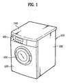
- FIG 1 illustrates a perspective view of a laundry dryer having a cabinet in accordance with a first preferred embodiment of the present invention
- FIG. 2 illustrates a perspective view of a first embodiment base of a cabinet of the present invention
- FIG. 3 illustrates a section of the base across a line I-I in FIG. 2 ;
- FIG 4 illustrates a section of the base across a line II-II in FIG. 2 ;
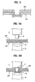
- FIG. 5 illustrates a section of a joint portion of a base and a rear panel
- FIGS. 6A and 6B illustrate the steps of a process for joining a base to a rear panel with Tox round joint
- FIG. 7 illustrates a perspective view of a second embodiment base of a cabinet of the present invention
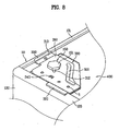
- FIG 8 illustrates a perspective view of a comer of an underside of a base having a leg mounting member to be provided to a cabinet secured thereto;
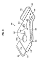
- FIG. 9 illustrates a perspective view of the leg mounting member in FIG. 8 .
- FIG 10 illustrates an exploded perspective view of the leg mounting member separated from the cabinet in FIG. 9 .
- a laundry dryer having a cabinet for a home appliance in accordance with a preferred embodiment of the present invention applied thereto, and a first embodiment base applied to the cabinet will be described, with reference to FIGS. 2 and 3 .
- the laundry dryer includes a cabinet 100 forming an exterior of the laundry dryer, and a drum (not shown) in the cabinet for holding a drying object.
- the cabinet 100 of the laundry dryer includes a base 110, a front panel 120, a front of the cabinet 100, having a bottom edge joined to a front edge of the base 110, side panels 130 joined to opposite edges of the base 110, to form sides of the cabinet 100, a rear panel (not shown) having a bottom edge joined to a rear edge of the base 110, to form a rear of the cabinet, and a top panel 140 joined to top edges of the front panel 120, the side panels, and the rear panel, to form a top of the cabinet 100.
- the front panel 120 has a control panel 121 at an upper portion, for operating the laundry dryer, an opening (not shown) at a center portion for introduction of the drying object, such as laundry, and a door 122 rotatably secured to one side of the opening, for opening/closing the opening.
- the drum is configured to rotate by a belt connected to a driving motor (not shown) provided to a lower space of the cabinet 100.
- the drum has a belt groove (not shown) in an outside circumference for placing the belt therein.
- the drum is connected to an air exhaust duct assembly for guiding exhaust air from the drum to an outside of the cabinet.
- an air exhaust duct assembly for guiding exhaust air from the drum to an outside of the cabinet.
- a fan for forcing air to flow.
- a first embodiment base 110 to be provided to the cabinet for a home appliance, i.e., a cabinet for a laundry dryer, in accordance with a preferred embodiment of the present invention will be described with reference to FIGS. 2 to 4 .
- FIG 2 illustrates a perspective view of a first embodiment base of a cabinet of the present invention
- FIG. 3 illustrates a section of the base across a line I-I in FIG. 2
- FIG. 4 illustrates a section of the base across a line II-II in FIG 2 .
- the first embodiment base 110 includes at least one reinforcing projection from a predetermined portion of the base 110, for improving a strength of the base.
- a flange 111 bent upward of a predetermined height for joining to the front panel 120.
- the at least one reinforcing projection includes reinforcing beads 112 at edges of the base 110. If the base is square like the embodiment, the reinforcing beads 112 project upward along the edges of the base 110.
- All of the reinforcing beads 112 may be connected to form a square line, or the reinforcing beads 112 may be formed along the edges excluding four comers of the base 110. it is preferable that the reinforcing bead 112 has a round cross section.
- the reinforcing beads 112 may be formed at some of the edges of the base 110, but it is preferable that the bead 112 is formed at every edge of the base 110 extended along the edge for minimizing bending and distortion liable to occur at the base 110.
- the reinforcing beads 112 prevent bending or distortion of the base 110 caused by loads on the base 110, when the side panels 130, and the rear panel are joined to the base 110, and various components, such as the drum, are mounted in the cabinet.
- At least one of the reinforcing projection may include a leg mounting portion 113 projected from one side of the base 110, for mounting a leg 150 for supporting the cabinet 100. It is preferable that the leg mounting portion 113 is provided to every comer of the base 110.
- the leg mounting portion 113 has one side recessed compared to an adjacent region, and the other side projected compared to an adjacent region.
- the leg mounting portion 113 has a leg mounting hole 113a for mounting the leg 150.
- the leg mounting portion 113 prevents the base 110 from being bent or suffering from damage even if there is a load concentrated on the comer of the base 110 to which the leg 150 is mounted.
- the first embodiment base 110 includes all of the leg mounting portions 113 at comers of the base 110 respectively, and the reinforcing beads 112 extended along the edges of the base 110, respectively.
- the reinforcing bead 112 and the leg mounting portion 113 are projected to opposite directions.
- the reinforcing bead 112 is projected upward, and the leg mounting portion 113 is projected downward.
- the leg mounting portion 113 is formed to project toward the ground.
- the leg mounting portion 113 is projected in a direction opposite to the direction of proj ection of the reinforcing bead 112, because, if the leg mounting portion 113 is projected in a direction the same with the projection direction of the reinforcing bead 112, there will be wrinkles formed in the base 110.
- leg mounting portion 113 is projected in a direction opposite to the direction of projection of the reinforcing bead 112, for preventing formation of the wrinkles in formation of the base 110.
- the reinforcing bead 112 and the leg mounting portion 113 of the base may be formed by a variety of methods, such as injection molding, or the like.
- the base 110 may include a reinforcing rib (not shown) instead of the reinforcing bead 112.
- a method for joining the first embodiment base 110 to the rear panel will be described with reference to FIGS. 5, 6A, and 6B .
- the base 110 is joined to a bottom flange 160 of the rear panel with by a Tox round joint method ("TOX" is a registered trademark).
- TOX is a registered trademark.
- the Tox round joint method joins two plates, easily.
- press die D having one side provided with a truncated conical press punch P, and the other side provided with a substantially circular recess 10.
- the recess 10 in the press die D has a diameter greater than a diameter of the press punch P, with a bottom thereof having an edge lower than a center.
- the Tox round joint method is applicable to joining of the side panel 130 to the base 110, and joining of the side panel 130 to the rear panel.
- the rear panel can be join to the base 110 by other methods, such as screw fastening, or curling of plates, because the Tox round joint method is simple, and requires components less than other joining methods, the Tox round joint method can shorten an assembly time period of the cabinet 100, and prevents the problem of accumulation of tolerances that occurs in fabrication of components.
- the base 110 of the cabinet of the present invention does not require to include all of the reinforcing beads 112, and the leg mounting portions 113, necessarily.
- FIG. 7 illustrates a perspective view of a second embodiment base of a cabinet of the present invention.
- the second embodiment base 210 includes no reinforcing beads 112 at the edges, and other parts identical to the part of the first embodiment base 210, of which description will be omitted.
- the base 210 may have the reinforcing beads 112 and/or the leg mounting portions 113 for improving strength, for preventing bending and distortion of the base 210.
- FIG. 8 illustrates a perspective view of a comer of an underside of a base having a leg mounting member to be provided to a cabinet secured thereto
- FIG. 9 illustrates a perspective view of the leg mounting member in FIG 8
- FIG. 10 illustrates an exploded perspective view of the leg mounting member separated from the cabinet in FIG. 9 .
- the leg mounting member 300 is provided to the comparative example base 400 for preventing deformation of the base 400.
- the leg mounting member 300 may be joined to the leg mounting portion described in the different embodiment of bases 110, and 210.
- the comparative example base 400 includes the leg mounting portion projected downward, the projections like the bases 110 and 210 of the first and second embodiments are not required, necessarily.
- the leg mounting member 300 is mounted on an underside of the leg mounting portion 113, for supporting the base 400, and has a leg mounting hole 300a passed through the leg mounting member 300 in correspondence to the leg mounting hole 113a.
- leg mounting member 300 is configured to support at least one of the front panel 120 or the side panel 130.
- the leg mounting member 300 has one side for supporting the front panel 120, and the other side for supporting the side panel 130.
- the leg mounting member 300 is mounted at each of front opposite comers of the base 400, but the mounting positions are not limited to these.
- the leg mounting member 300 will be described, in more detail.
- the leg mounting member 300 includes a base supporting portion 310 joined to the leg mounting portion for supporting the base 400, a front panel supporting portion 320 for supporting the front panel 120, and a side panel supporting portion 330 for supporting the side panel 130.
- the base supporting portion 310 has the leg mounting hole 330a, and a plurality of screw fastening holes 311 in the vicinity of the leg mounting hole 330a, particularly in a front portion of the base supporting portion 310 for fastening the leg mounting member 300 to the base 110 with screws S.
- the base supporting portion 310 further has a leg anti-loosening hole 312 for preventing the leg from loosening.
- the leg anti-loosening hole 312 is extended from the leg mounting hole 330a in a radial direction, and has one side edge 312a, and the other side edge 312b respectively having heights different from each other, so as to serve as a washer.
- the front panel supporting portion 320 at a front of the leg mounting member 300, supports the lower edge of the front panel 120, i.e., the flange 123 of the front panel.
- a fixing projection 321 bent upward from the front edge, for inserting in a fixing slot 123a in the flange 123 of the front panel, for fixing the bottom edge of the front panel 120.
- the front panel supporting portion 320 enables an easy joining of the front panel 120, as well as supports a portion of a load of the front panel 120, to reduce the load on the base 400.
- the side panel supporting portion 330 at a side of the leg mounting member, for supporting a bottom edge of the side panel 130, i.e., the flange 131 of the side panel.
- a supplementary supporting portion 313 may be formed projected to form a step higher than the base supporting portion 310, between the base supporting portion 310 and the side panel supporting portion 330.
- the leg mounting member 300 further includes an align member for aligning the leg mounting member 300 with a predetermined position of the base 400.
- the align member includes an align projection 341 bent upward from a rear edge of the base supporting portion 310 for inserting in an align slot 410 in a predetermined position of the base 400.
- the align member may further include a holding projection 342 formed as one body at a top of the align projection 341 for being held at an upper surface of the base.
- the holding projection 342 is perpendicular to the align projection 341, and parallel to the base supporting portion 310.
- the holding projection 342 passes the align slot 410 before the align projection 341 in a process the leg mounting member 300 is joined to the leg mounting portion of the base 400, and is held at the upper surface of the base 400 as an upper surface of the base supporting portion 310 is brought into close contact with the underside of the leg mounting portion, to prevent the leg mounting member 300 from loose, and to enable easy fastening of the screws S.
- the align member further includes a supplementary align projection 343 projected upward from the base supporting portion 310.
- the supplementary align projection 343 is inserted in a supplementary align hole 420 in the leg mounting portion, for aligning a position of the leg mounting member 300, and making mounting of the leg mounting member 300 easy.
- the align member may include one of the align projection 341 and the supplementary align projection 343.
- the leg mounting member 300 may further include a supplementary bead 350 on the base supporting portion 310. It is preferable that the supplementary bead 350 is projected downward such that the leg mounting member 300 and the leg mounting portion are brought into close contact.
- a process for assembling the cabinet for a home appliance i.e., a cabinet for a laundry dryer, will be described.
- the leg mounting member 300 After joining the side panel 130 to the base 400, the leg mounting member 300 is attached to the leg mounting portion of the base 400.
- the leg mounting member 300 is properly positioned, without loosening of the leg mounting member 300.
- the side panel supporting portion 330 of the leg mounting member 300 supports the flange 131 at the bottom edge of the side panel.
- the fixing projection 321 on the front panel supporting portion is inserted in the fixing slot in the flange 123 of the front panel, falling off of the bottom edge of the front panel is prevented, and a portion of load of the front panel 120 is supported on the leg mounting member 300. Then, the front panel 120 is fastened to the front of the cabinet with fastening devices, such as screws (not shown) or hooks (not shown).
- the laundry- dryer Upon putting a drying object, such as clothes, in a drum through the opening in the cabinet 100, and closing the door 122, the laundry- dryer is put into operation by using the control panel 121.
- the drum is rotated by the driving motor and the belt, the hot air introduced into the rotating drum extracts moisture from the drying object, and carries away through the exhaust duct.
- the cabinet for a home appliance of the present invention has the following advantages.
- the reinforcing projections from the base prevents the base from bending or distortion.
- the joining of the side panel and the rear panel to the base with Tox round joint makes assembly of the cabinet easy, and reduces a number of components.
- leg mounting member mounted to the base prevents the base from deformation.
- the leg mounting member mounted to the base that can support loads of the front panel and the side panel prevents the base from deformation caused by a load from an upper side.
- the fixing projection on the leg mounting member enables easy joining of the front panel.
- the align member on the leg mounting member makes joining of the leg mounting member easy.
- the reinforcing bead on the leg mounting member for improving strength permits to prevent deformation of the leg mounting member and the base.
- the invention provides a cabinet for a home appliance including a front panel, side panels, and a base, wherein the base includes at least one reinforcing projection at a predetermined portion of the base for improving strength of the base, thereby providing a cabinet for a home appliance having a base with improved strength against load and vibration, to prevent deformation or damage to the base.
Landscapes
- Engineering & Computer Science (AREA)
- Textile Engineering (AREA)
- Main Body Construction Of Washing Machines And Laundry Dryers (AREA)
Claims (14)
- Gehäuse (100) für ein Haushaltsgerät, welches Folgendes umfasst:ein Frontpaneel (120);Seitenpaneele (130); undeine Basis (110; 210; 400);wobei die Basis (110; 210; 400) mindestens einen Verstärkungsvorsprung an einem vorgegebenen Abschnitt der Basis (110; 210; 400) enthält, um die Festigkeit der Basis (110; 210; 400) zu erhöhen;wobei der mindestens eine Verstärkungsvorsprung einen Beinmontageabschnitt (113) enthält, um ein Bein (150) daran zu montieren, undwobei der mindestens eine Verstärkungsvorsprung des Weiteren eine Verstärkungswulst (112) enthält,dadurch gekennzeichnet, dassdie Basis (110; 210; 400) zusätzlich zu den Front- und Seitenpaneelen (120, 130) vorhanden ist;der Beinmontageabschnitt (113) zu einer Seite der Basis (110; 210; 400) in einer Richtung hervorsteht, die einer Vorsprungsrichtung der Verstärkungswulst (112) entgegengesetzt ist;die Verstärkungswulst (112) an einem Rand der Basis (110; 210; 400) angeordnet ist;der Beinmontageabschnitt (113) so ausgebildet ist, dass er von der Basis hervorsteht;ein Beinmontageelement (300) an einer Unterseite des Beinmontageabschnitts (113) montiert ist und das Frontpaneel (120) und/oder das Seitenpaneel (130) stützt;das Beinmontageelement (300) einen Frontpaneel (120)-Stützabschnitt enthält, der einen Befestigungsvorsprung (321) aufweist, der in einen unteren Rand des Frontpaneels (120) eingesetzt ist, um das Frontpaneel (120) zu stützen; unddas Beinmontageelement (300) einen Seitenpaneel (130)-Stützabschnitt zum Stützen des Seitenpaneels (130) enthält.
- Gehäuse (100) nach Anspruch 1, wobei die Verstärkungswulst (112) an einem Rand der Basis (110; 210; 400) angeordnet ist.
- Gehäuse (100) nach Anspruch 1 oder 2, wobei die Verstärkungswulst (112) nach oben hervorsteht.
- Gehäuse (100) nach Anspruch 1, wobei der Beinmontageabschnitt (113) so ausgebildet ist, dass er nach unten hervorsteht.
- Gehäuse (100) nach einem der Ansprüche 1 bis 4, wobei die Basis (110; 210; 400) des Weiteren ein Beinmontageelement (300) enthält, das an den Beinmontageabschnitt (113) montiert ist, um die Festigkeit der Basis (110; 210; 400) zu erhöhen, wobei das Beinmontageelement (300) ein Beinmontageloch aufweist, das in einer Aufwärts/Abwärts-Richtung verläuft.
- Gehäuse (100) nach Anspruch 1, wobei das Beinmontageelement (300) einen Befestigungsvorsprung (321) enthält, der in einen unteren Rand des Frontpaneels (120) eingesetzt ist, um das Frontpaneel (120) zu befestigen.
- Gehäuse (100) nach einem der Ansprüche 5 bis 6, wobei das Beinmontageelement (300) ein Ausrichtungselement enthält, um das Beinmontageelement (300) auf eine vorgegebene Position der Basis (110; 210; 400) auszurichten.
- Gehäuse (100) nach Anspruch 7, wobei das Ausrichtungselement einen Ausrichtungsvorsprung (341) enthält, der in einen Schlitz (410) in einer vorgegebenen Position der Basis (110; 210; 400) einzusetzen ist.
- Gehäuse (100) nach Anspruch 8, wobei das Ausrichtungselement des Weiteren einen Haltevorsprung (342) enthält, der einstückig mit dem Ausrichtungsvorsprung (341) ausgebildet ist, um an einer Oberseite der Basis (110; 210; 400) gehalten zu werden.
- Gehäuse (100) nach einem der Ansprüche 5 bis 9, wobei das Beinmontageelement (300) ein Bein-Lockerungsverhinderungsloch enthält, das sich von dem Beinmontageloch in einer radialen Richtung erstreckt, und einen Seitenrand aufweist, und die andere Seite jeweils Höhen aufweist, die voneinander verschieden sind.
- Gehäuse (100) nach einem der Ansprüche 5 bis 10, wobei das Beinmontageelement (300) eine Zusatzwulst (350) enthält, um die Festigkeit des Beinmontageelements (300) zu erhöhen.
- Gehäuse (100) nach einem der Ansprüche 1 bis 11, wobei der Beinmontageabschnitt (113) von einer Ecke der Basis (110; 210; 400) nach unten hervorsteht.
- Gehäuse (100) nach Anspruch 1, wobei das Beinmontageelement (300) einen Haltevorsprung (342) enthält, der an einem oberen Ende des Ausrichtungsvorsprungs (341) einstückig mit dem Ausrichtungsvorsprung (341) ausgebildet ist, um an einer Oberseite der Basis (110; 210; 400) gehalten zu werden.
- Gehäuse (100) nach Anspruch 1 oder 2, wobei das Beinmontageelement (300) eine Zusatzwulst (350) enthält, die nach unten hervorsteht, um die Festigkeit des Beinmontageelements (300) zu erhöhen.
Applications Claiming Priority (4)
| Application Number | Priority Date | Filing Date | Title |
|---|---|---|---|
| KR2003100046 | 2003-12-30 | ||
| KR1020030100046A KR100587319B1 (ko) | 2003-12-30 | 2003-12-30 | 의류건조기 |
| KR1020030100045A KR100587318B1 (ko) | 2003-12-30 | 2003-12-30 | 의류건조기의 베이스 보강구조 |
| KR2003100045 | 2003-12-30 |
Publications (2)
| Publication Number | Publication Date |
|---|---|
| EP1550397A1 EP1550397A1 (de) | 2005-07-06 |
| EP1550397B1 true EP1550397B1 (de) | 2013-02-13 |
Family
ID=34576057
Family Applications (1)
| Application Number | Title | Priority Date | Filing Date |
|---|---|---|---|
| EP04030970A Expired - Lifetime EP1550397B1 (de) | 2003-12-30 | 2004-12-29 | Gehäuse für Haushaltsgerät |
Country Status (4)
| Country | Link |
|---|---|
| US (1) | US20050138836A1 (de) |
| EP (1) | EP1550397B1 (de) |
| CN (1) | CN100419147C (de) |
| AU (1) | AU2004242499B2 (de) |
Families Citing this family (11)
| Publication number | Priority date | Publication date | Assignee | Title |
|---|---|---|---|---|
| DE102004055942A1 (de) * | 2004-11-19 | 2006-05-24 | BSH Bosch und Siemens Hausgeräte GmbH | Wäschetrockner |
| KR100662369B1 (ko) * | 2004-11-30 | 2007-01-02 | 엘지전자 주식회사 | 열풍공급용 옷걸이가 구비된 복합식 건조장치 |
| KR100710395B1 (ko) * | 2006-01-25 | 2007-04-24 | 엘지전자 주식회사 | 의류 건조기 |
| KR101308510B1 (ko) * | 2007-11-05 | 2013-09-12 | 동부대우전자 주식회사 | 히터 내장형 흡기관을 구비하는 건조기 |
| KR101256145B1 (ko) * | 2007-11-05 | 2013-04-23 | 동부대우전자 주식회사 | 히터 내장형 흡기관을 구비하는 건조기 |
| US8215729B2 (en) | 2010-04-13 | 2012-07-10 | Whirlpool Corporation | Appliance cabinet and method of assembling same |
| CN102997583A (zh) * | 2012-12-12 | 2013-03-27 | 合肥美的荣事达电冰箱有限公司 | 用于冰箱的背板和具有该背板的冰箱 |
| SI25092A (sl) * | 2015-11-11 | 2017-05-31 | Gorenje Gospodinjski Aparati, D.D. | Pralni stroj z nastavljivimi podporami |
| WO2019043971A1 (ja) * | 2017-09-01 | 2019-03-07 | シャープ株式会社 | 洗濯機 |
| US10619920B2 (en) * | 2017-10-02 | 2020-04-14 | Whirlpool Corporation | Two piece base assembly of a dryer |
| KR102758310B1 (ko) * | 2019-05-24 | 2025-01-23 | 삼성전자주식회사 | 세탁기 |
Family Cites Families (22)
| Publication number | Priority date | Publication date | Assignee | Title |
|---|---|---|---|---|
| US1807014A (en) * | 1931-05-26 | Cabinet gas heater | ||
| US2270710A (en) * | 1939-02-27 | 1942-01-20 | Roper Corp Geo D | Cabinet construction for ranges and the like |
| US2385154A (en) * | 1943-11-12 | 1945-09-18 | Charles R Nalle | Adjustable caster socket |
| US2964371A (en) * | 1958-02-17 | 1960-12-13 | Imp Brass Mfg Co | Display merchandiser |
| US3304032A (en) * | 1965-01-13 | 1967-02-14 | Gen Electric | Self-balancing support mechanism |
| JPS5410569A (en) * | 1977-06-27 | 1979-01-26 | Hitachi Ltd | Washer |
| ES470524A1 (es) * | 1978-05-26 | 1979-02-01 | Domar Sa | Perfeccionamientos en los bastidores y carcasas de maquinas lavadoras de ropa |
| US4319793A (en) * | 1979-06-26 | 1982-03-16 | Royston Manufacturing Corporation | Sheet metal cabinet |
| DE2929222C2 (de) * | 1979-07-19 | 1985-11-28 | Licentia Patent-Verwaltungs-Gmbh, 6000 Frankfurt | Höhenverstellbarer Standfuß für Waschmaschinen, Wäschetrockner, Geschirrspülmaschinen und dgl. |
| ES252680Y (es) * | 1980-07-31 | 1981-05-16 | Maquina lavadora de ropa | |
| JPS5886195A (ja) * | 1981-11-17 | 1983-05-23 | 株式会社東芝 | 洗濯機 |
| US4618193A (en) * | 1983-12-07 | 1986-10-21 | Whirlpool Corporation | Cabinet construction for an automatic washer |
| US4909580A (en) * | 1988-10-11 | 1990-03-20 | General Electric Company | Fabric dryer housing |
| IT227597Y1 (it) * | 1992-07-14 | 1997-12-15 | Merloni Elettrodomestici Spa | Macchina lavabiancheria con mobile a pareti verticali irrigidite. |
| JPH0768086A (ja) * | 1993-09-07 | 1995-03-14 | Mitsui Petrochem Ind Ltd | 洗濯機 |
| US5593219A (en) * | 1995-12-14 | 1997-01-14 | Ho; Hsin C. | Mainframe housing of a personal computer |
| DE29714220U1 (de) * | 1997-08-12 | 1997-09-25 | Blumenschein, Benjamin, 71404 Korb | Sockelgestell für Haushaltsgeräte |
| DE19812328C1 (de) * | 1998-03-20 | 1999-09-23 | Whirlpool Co | Haushaltgerät mit einem aus Blech-Wandelementen gebildeten Gehäuse, insbesondere Waschmaschine oder Geschirrspülmaschine |
| JP4081850B2 (ja) * | 1998-04-28 | 2008-04-30 | 松下電器産業株式会社 | ドラム式洗濯機 |
| CN2330682Y (zh) * | 1998-08-11 | 1999-07-28 | 无锡小天鹅股份有限公司 | 一种洗衣机底座与机箱固定装置 |
| CN2474557Y (zh) * | 2001-03-21 | 2002-01-30 | 无锡小天鹅股份有限公司 | 洗衣机脱水桶的桶底结构 |
| AU2003262464B2 (en) * | 2002-11-28 | 2006-07-06 | Lg Electronics Inc. | Washing machine |
-
2004
- 2004-12-29 EP EP04030970A patent/EP1550397B1/de not_active Expired - Lifetime
- 2004-12-30 CN CNB2004101041823A patent/CN100419147C/zh not_active Expired - Fee Related
- 2004-12-30 AU AU2004242499A patent/AU2004242499B2/en not_active Ceased
- 2004-12-30 US US11/024,806 patent/US20050138836A1/en not_active Abandoned
Also Published As
| Publication number | Publication date |
|---|---|
| AU2004242499B2 (en) | 2010-07-01 |
| AU2004242499A1 (en) | 2005-07-14 |
| CN1637195A (zh) | 2005-07-13 |
| CN100419147C (zh) | 2008-09-17 |
| US20050138836A1 (en) | 2005-06-30 |
| EP1550397A1 (de) | 2005-07-06 |
Similar Documents
| Publication | Publication Date | Title |
|---|---|---|
| EP1550397B1 (de) | Gehäuse für Haushaltsgerät | |
| US7494197B2 (en) | Cabinet for home appliance | |
| US20040020073A1 (en) | Top cover assembly for laundry dryer | |
| US8136896B2 (en) | Laundry treating machine | |
| US20040168484A1 (en) | Washing machine | |
| EP2314754B1 (de) | Stützvorrichtung und Waschmaschine damit | |
| US7621156B2 (en) | Cabinet for washing machine and washing machine using the same | |
| CN113308842A (zh) | 堆叠式衣物处理装置 | |
| US20050122011A1 (en) | Cabinet structure of home appliance | |
| KR101012361B1 (ko) | 의류건조기의 탑브라켓과 사이드 캐비닛의 결합구조 | |
| KR100799994B1 (ko) | 드럼타입 세탁/건조장치의 적층킷트 | |
| US5533367A (en) | Appliance shipping restraint assembly | |
| EP3124675B1 (de) | Waschmaschine und/oder trockner | |
| KR102852427B1 (ko) | 의류처리장치 | |
| US11072882B2 (en) | Universal pedestal for a laundry appliance | |
| EP1550761B1 (de) | Waschmaschine | |
| CN223150872U (zh) | 衣物处理设备 | |
| KR100587318B1 (ko) | 의류건조기의 베이스 보강구조 | |
| KR20050067916A (ko) | 드럼타입 세탁/건조장치의 적층킷트 | |
| CN121629722A (zh) | 衣物处理设备 | |
| KR101074703B1 (ko) | 드럼세탁기 메인회로 조립체 고정구조물 | |
| KR20050070474A (ko) | 의류건조기 | |
| KR20080002453A (ko) | 받침대용 브래킷을 구비하는 세탁기 |
Legal Events
| Date | Code | Title | Description |
|---|---|---|---|
| PUAI | Public reference made under article 153(3) epc to a published international application that has entered the european phase |
Free format text: ORIGINAL CODE: 0009012 |
|
| 17P | Request for examination filed |
Effective date: 20041229 |
|
| AK | Designated contracting states |
Kind code of ref document: A1 Designated state(s): AT BE BG CH CY CZ DE DK EE ES FI FR GB GR HU IE IS IT LI LT LU MC NL PL PT RO SE SI SK TR |
|
| AX | Request for extension of the european patent |
Extension state: AL BA HR LV MK YU |
|
| AKX | Designation fees paid |
Designated state(s): AT BE BG CH CY CZ DE DK EE ES FI FR GB GR HU IE IS IT LI LT LU MC NL PL PT RO SE SI SK TR |
|
| 17Q | First examination report despatched |
Effective date: 20070525 |
|
| GRAP | Despatch of communication of intention to grant a patent |
Free format text: ORIGINAL CODE: EPIDOSNIGR1 |
|
| GRAS | Grant fee paid |
Free format text: ORIGINAL CODE: EPIDOSNIGR3 |
|
| GRAA | (expected) grant |
Free format text: ORIGINAL CODE: 0009210 |
|
| AK | Designated contracting states |
Kind code of ref document: B1 Designated state(s): AT BE BG CH CY CZ DE DK EE ES FI FR GB GR HU IE IS IT LI LT LU MC NL PL PT RO SE SI SK TR |
|
| REG | Reference to a national code |
Ref country code: GB Ref legal event code: FG4D |
|
| REG | Reference to a national code |
Ref country code: AT Ref legal event code: REF Ref document number: 596021 Country of ref document: AT Kind code of ref document: T Effective date: 20130215 |
|
| REG | Reference to a national code |
Ref country code: IE Ref legal event code: FG4D |
|
| REG | Reference to a national code |
Ref country code: DE Ref legal event code: R096 Ref document number: 602004040949 Country of ref document: DE Effective date: 20130411 |
|
| REG | Reference to a national code |
Ref country code: AT Ref legal event code: MK05 Ref document number: 596021 Country of ref document: AT Kind code of ref document: T Effective date: 20130213 |
|
| REG | Reference to a national code |
Ref country code: NL Ref legal event code: VDEP Effective date: 20130213 |
|
| REG | Reference to a national code |
Ref country code: LT Ref legal event code: MG4D |
|
| PG25 | Lapsed in a contracting state [announced via postgrant information from national office to epo] |
Ref country code: LT Free format text: LAPSE BECAUSE OF FAILURE TO SUBMIT A TRANSLATION OF THE DESCRIPTION OR TO PAY THE FEE WITHIN THE PRESCRIBED TIME-LIMIT Effective date: 20130213 Ref country code: IS Free format text: LAPSE BECAUSE OF FAILURE TO SUBMIT A TRANSLATION OF THE DESCRIPTION OR TO PAY THE FEE WITHIN THE PRESCRIBED TIME-LIMIT Effective date: 20130613 Ref country code: CY Free format text: LAPSE BECAUSE OF FAILURE TO SUBMIT A TRANSLATION OF THE DESCRIPTION OR TO PAY THE FEE WITHIN THE PRESCRIBED TIME-LIMIT Effective date: 20130213 Ref country code: BG Free format text: LAPSE BECAUSE OF FAILURE TO SUBMIT A TRANSLATION OF THE DESCRIPTION OR TO PAY THE FEE WITHIN THE PRESCRIBED TIME-LIMIT Effective date: 20130513 Ref country code: SE Free format text: LAPSE BECAUSE OF FAILURE TO SUBMIT A TRANSLATION OF THE DESCRIPTION OR TO PAY THE FEE WITHIN THE PRESCRIBED TIME-LIMIT Effective date: 20130213 Ref country code: AT Free format text: LAPSE BECAUSE OF FAILURE TO SUBMIT A TRANSLATION OF THE DESCRIPTION OR TO PAY THE FEE WITHIN THE PRESCRIBED TIME-LIMIT Effective date: 20130213 Ref country code: ES Free format text: LAPSE BECAUSE OF FAILURE TO SUBMIT A TRANSLATION OF THE DESCRIPTION OR TO PAY THE FEE WITHIN THE PRESCRIBED TIME-LIMIT Effective date: 20130524 |
|
| PG25 | Lapsed in a contracting state [announced via postgrant information from national office to epo] |
Ref country code: GR Free format text: LAPSE BECAUSE OF FAILURE TO SUBMIT A TRANSLATION OF THE DESCRIPTION OR TO PAY THE FEE WITHIN THE PRESCRIBED TIME-LIMIT Effective date: 20130514 Ref country code: PT Free format text: LAPSE BECAUSE OF FAILURE TO SUBMIT A TRANSLATION OF THE DESCRIPTION OR TO PAY THE FEE WITHIN THE PRESCRIBED TIME-LIMIT Effective date: 20130613 Ref country code: PL Free format text: LAPSE BECAUSE OF FAILURE TO SUBMIT A TRANSLATION OF THE DESCRIPTION OR TO PAY THE FEE WITHIN THE PRESCRIBED TIME-LIMIT Effective date: 20130213 Ref country code: SI Free format text: LAPSE BECAUSE OF FAILURE TO SUBMIT A TRANSLATION OF THE DESCRIPTION OR TO PAY THE FEE WITHIN THE PRESCRIBED TIME-LIMIT Effective date: 20130213 Ref country code: FI Free format text: LAPSE BECAUSE OF FAILURE TO SUBMIT A TRANSLATION OF THE DESCRIPTION OR TO PAY THE FEE WITHIN THE PRESCRIBED TIME-LIMIT Effective date: 20130213 Ref country code: BE Free format text: LAPSE BECAUSE OF FAILURE TO SUBMIT A TRANSLATION OF THE DESCRIPTION OR TO PAY THE FEE WITHIN THE PRESCRIBED TIME-LIMIT Effective date: 20130213 |
|
| PG25 | Lapsed in a contracting state [announced via postgrant information from national office to epo] |
Ref country code: DK Free format text: LAPSE BECAUSE OF FAILURE TO SUBMIT A TRANSLATION OF THE DESCRIPTION OR TO PAY THE FEE WITHIN THE PRESCRIBED TIME-LIMIT Effective date: 20130213 Ref country code: RO Free format text: LAPSE BECAUSE OF FAILURE TO SUBMIT A TRANSLATION OF THE DESCRIPTION OR TO PAY THE FEE WITHIN THE PRESCRIBED TIME-LIMIT Effective date: 20130213 Ref country code: CZ Free format text: LAPSE BECAUSE OF FAILURE TO SUBMIT A TRANSLATION OF THE DESCRIPTION OR TO PAY THE FEE WITHIN THE PRESCRIBED TIME-LIMIT Effective date: 20130213 Ref country code: SK Free format text: LAPSE BECAUSE OF FAILURE TO SUBMIT A TRANSLATION OF THE DESCRIPTION OR TO PAY THE FEE WITHIN THE PRESCRIBED TIME-LIMIT Effective date: 20130213 Ref country code: NL Free format text: LAPSE BECAUSE OF FAILURE TO SUBMIT A TRANSLATION OF THE DESCRIPTION OR TO PAY THE FEE WITHIN THE PRESCRIBED TIME-LIMIT Effective date: 20130213 Ref country code: EE Free format text: LAPSE BECAUSE OF FAILURE TO SUBMIT A TRANSLATION OF THE DESCRIPTION OR TO PAY THE FEE WITHIN THE PRESCRIBED TIME-LIMIT Effective date: 20130213 |
|
| PLBE | No opposition filed within time limit |
Free format text: ORIGINAL CODE: 0009261 |
|
| STAA | Information on the status of an ep patent application or granted ep patent |
Free format text: STATUS: NO OPPOSITION FILED WITHIN TIME LIMIT |
|
| PG25 | Lapsed in a contracting state [announced via postgrant information from national office to epo] |
Ref country code: IT Free format text: LAPSE BECAUSE OF FAILURE TO SUBMIT A TRANSLATION OF THE DESCRIPTION OR TO PAY THE FEE WITHIN THE PRESCRIBED TIME-LIMIT Effective date: 20130213 |
|
| 26N | No opposition filed |
Effective date: 20131114 |
|
| REG | Reference to a national code |
Ref country code: DE Ref legal event code: R097 Ref document number: 602004040949 Country of ref document: DE Effective date: 20131114 |
|
| REG | Reference to a national code |
Ref country code: CH Ref legal event code: PL |
|
| PG25 | Lapsed in a contracting state [announced via postgrant information from national office to epo] |
Ref country code: MC Free format text: LAPSE BECAUSE OF FAILURE TO SUBMIT A TRANSLATION OF THE DESCRIPTION OR TO PAY THE FEE WITHIN THE PRESCRIBED TIME-LIMIT Effective date: 20130213 Ref country code: LU Free format text: LAPSE BECAUSE OF FAILURE TO SUBMIT A TRANSLATION OF THE DESCRIPTION OR TO PAY THE FEE WITHIN THE PRESCRIBED TIME-LIMIT Effective date: 20131229 |
|
| REG | Reference to a national code |
Ref country code: IE Ref legal event code: MM4A |
|
| PG25 | Lapsed in a contracting state [announced via postgrant information from national office to epo] |
Ref country code: LI Free format text: LAPSE BECAUSE OF NON-PAYMENT OF DUE FEES Effective date: 20131231 Ref country code: CH Free format text: LAPSE BECAUSE OF NON-PAYMENT OF DUE FEES Effective date: 20131231 Ref country code: IE Free format text: LAPSE BECAUSE OF NON-PAYMENT OF DUE FEES Effective date: 20131229 |
|
| PG25 | Lapsed in a contracting state [announced via postgrant information from national office to epo] |
Ref country code: TR Free format text: LAPSE BECAUSE OF FAILURE TO SUBMIT A TRANSLATION OF THE DESCRIPTION OR TO PAY THE FEE WITHIN THE PRESCRIBED TIME-LIMIT Effective date: 20130213 |
|
| PG25 | Lapsed in a contracting state [announced via postgrant information from national office to epo] |
Ref country code: HU Free format text: LAPSE BECAUSE OF FAILURE TO SUBMIT A TRANSLATION OF THE DESCRIPTION OR TO PAY THE FEE WITHIN THE PRESCRIBED TIME-LIMIT; INVALID AB INITIO Effective date: 20041229 |
|
| REG | Reference to a national code |
Ref country code: FR Ref legal event code: PLFP Year of fee payment: 12 |
|
| REG | Reference to a national code |
Ref country code: FR Ref legal event code: PLFP Year of fee payment: 13 |
|
| PGFP | Annual fee paid to national office [announced via postgrant information from national office to epo] |
Ref country code: FR Payment date: 20161114 Year of fee payment: 13 Ref country code: GB Payment date: 20161110 Year of fee payment: 13 Ref country code: DE Payment date: 20161107 Year of fee payment: 13 |
|
| REG | Reference to a national code |
Ref country code: DE Ref legal event code: R119 Ref document number: 602004040949 Country of ref document: DE |
|
| GBPC | Gb: european patent ceased through non-payment of renewal fee |
Effective date: 20171229 |
|
| REG | Reference to a national code |
Ref country code: FR Ref legal event code: ST Effective date: 20180831 |
|
| PG25 | Lapsed in a contracting state [announced via postgrant information from national office to epo] |
Ref country code: FR Free format text: LAPSE BECAUSE OF NON-PAYMENT OF DUE FEES Effective date: 20180102 Ref country code: DE Free format text: LAPSE BECAUSE OF NON-PAYMENT OF DUE FEES Effective date: 20180703 |
|
| PG25 | Lapsed in a contracting state [announced via postgrant information from national office to epo] |
Ref country code: GB Free format text: LAPSE BECAUSE OF NON-PAYMENT OF DUE FEES Effective date: 20171229 |