EP1549520B1 - Dichtungsprofil mit zierleiste - Google Patents
Dichtungsprofil mit zierleiste Download PDFInfo
- Publication number
- EP1549520B1 EP1549520B1 EP03809275A EP03809275A EP1549520B1 EP 1549520 B1 EP1549520 B1 EP 1549520B1 EP 03809275 A EP03809275 A EP 03809275A EP 03809275 A EP03809275 A EP 03809275A EP 1549520 B1 EP1549520 B1 EP 1549520B1
- Authority
- EP
- European Patent Office
- Prior art keywords
- sealing
- area
- base body
- fastening
- weatherstrip
- Prior art date
- Legal status (The legal status is an assumption and is not a legal conclusion. Google has not performed a legal analysis and makes no representation as to the accuracy of the status listed.)
- Expired - Lifetime
Links
- 238000007789 sealing Methods 0.000 claims description 61
- 230000003014 reinforcing effect Effects 0.000 claims description 9
- 238000003780 insertion Methods 0.000 claims description 4
- 230000037431 insertion Effects 0.000 claims description 4
- AZDRQVAHHNSJOQ-UHFFFAOYSA-N alumane Chemical group [AlH3] AZDRQVAHHNSJOQ-UHFFFAOYSA-N 0.000 claims description 2
- 239000013013 elastic material Substances 0.000 claims description 2
- 238000005728 strengthening Methods 0.000 claims 1
- 238000005452 bending Methods 0.000 description 4
- 238000004519 manufacturing process Methods 0.000 description 2
- 238000000034 method Methods 0.000 description 2
- 229920002943 EPDM rubber Polymers 0.000 description 1
- 241001074085 Scophthalmus aquosus Species 0.000 description 1
- 230000015572 biosynthetic process Effects 0.000 description 1
- 238000011109 contamination Methods 0.000 description 1
- 239000013536 elastomeric material Substances 0.000 description 1
- 238000009434 installation Methods 0.000 description 1
- 229910052751 metal Inorganic materials 0.000 description 1
- 239000002184 metal Substances 0.000 description 1
- 238000000465 moulding Methods 0.000 description 1
Images


Classifications
-
- B—PERFORMING OPERATIONS; TRANSPORTING
- B60—VEHICLES IN GENERAL
- B60J—WINDOWS, WINDSCREENS, NON-FIXED ROOFS, DOORS, OR SIMILAR DEVICES FOR VEHICLES; REMOVABLE EXTERNAL PROTECTIVE COVERINGS SPECIALLY ADAPTED FOR VEHICLES
- B60J10/00—Sealing arrangements
- B60J10/80—Sealing arrangements specially adapted for opening panels, e.g. doors
- B60J10/86—Sealing arrangements specially adapted for opening panels, e.g. doors arranged on the opening panel
- B60J10/88—Sealing arrangements specially adapted for opening panels, e.g. doors arranged on the opening panel mounted on, or integral with, the glass-run seals
-
- B—PERFORMING OPERATIONS; TRANSPORTING
- B60—VEHICLES IN GENERAL
- B60J—WINDOWS, WINDSCREENS, NON-FIXED ROOFS, DOORS, OR SIMILAR DEVICES FOR VEHICLES; REMOVABLE EXTERNAL PROTECTIVE COVERINGS SPECIALLY ADAPTED FOR VEHICLES
- B60J10/00—Sealing arrangements
- B60J10/15—Sealing arrangements characterised by the material
- B60J10/18—Sealing arrangements characterised by the material provided with reinforcements or inserts
-
- B—PERFORMING OPERATIONS; TRANSPORTING
- B60—VEHICLES IN GENERAL
- B60J—WINDOWS, WINDSCREENS, NON-FIXED ROOFS, DOORS, OR SIMILAR DEVICES FOR VEHICLES; REMOVABLE EXTERNAL PROTECTIVE COVERINGS SPECIALLY ADAPTED FOR VEHICLES
- B60J10/00—Sealing arrangements
- B60J10/20—Sealing arrangements characterised by the shape
- B60J10/26—Sealing arrangements characterised by the shape characterised by the surface shape
- B60J10/265—Sealing arrangements characterised by the shape characterised by the surface shape the surface being primarily decorative
-
- B—PERFORMING OPERATIONS; TRANSPORTING
- B60—VEHICLES IN GENERAL
- B60J—WINDOWS, WINDSCREENS, NON-FIXED ROOFS, DOORS, OR SIMILAR DEVICES FOR VEHICLES; REMOVABLE EXTERNAL PROTECTIVE COVERINGS SPECIALLY ADAPTED FOR VEHICLES
- B60J10/00—Sealing arrangements
- B60J10/30—Sealing arrangements characterised by the fastening means
-
- B—PERFORMING OPERATIONS; TRANSPORTING
- B60—VEHICLES IN GENERAL
- B60J—WINDOWS, WINDSCREENS, NON-FIXED ROOFS, DOORS, OR SIMILAR DEVICES FOR VEHICLES; REMOVABLE EXTERNAL PROTECTIVE COVERINGS SPECIALLY ADAPTED FOR VEHICLES
- B60J10/00—Sealing arrangements
- B60J10/70—Sealing arrangements specially adapted for windows or windscreens
- B60J10/74—Sealing arrangements specially adapted for windows or windscreens for sliding window panes, e.g. sash guides
- B60J10/79—Sealing arrangements specially adapted for windows or windscreens for sliding window panes, e.g. sash guides for flush-glass windows, i.e. for windows flush with the vehicle body or the window frame
Definitions
- the present invention relates to a sealing profile for sealing a movable window pane in a motor vehicle door with a base body made of an elastic material, in which at least one sealing area and at least one attachment area for fixing the sealing profile is provided on a door flange, and with at least one trim strip, the one Aperture region and a protruding therefrom fastener which is positively secured to the body.
- Such a sealing profile is from the DE 197 36 899 C2 known.
- the sealing profile serves to seal a window slot in a motor vehicle door.
- the ornamental panel has a fastening element projecting from the panel area and, when the sealing profile is mounted on the vehicle, is positively encompassed by a pivotably arranged holding area of the sealing profile.
- a sealing arrangement for the door of a motor vehicle, which serves for sealing a shaft receiving a window is in the WO 01/87658 A1 described.
- the seal assembly consists of a inner window shaft seal and an outer window shaft seal together.
- a trim strip is arranged, which is composed of an upper part, which is provided with a shiny, for example made of metal, surface, and a lower part which is provided with a contrasting, for example, black surface.
- the upper part and the lower part each have a leg, which lie against each other and together form a Einsteckhist.
- the Einsteckhist formed by the legs of the two-part trim strip is frictionally held in a receiving channel.
- the inner surface of the receiving channel is provided with the adhesion-increasing fastening lips.
- An effective frictional connection also contributes to the fact that the receiving channel is encompassed by the upper semicircle of a cross-sectionally S-shaped reinforcing element which is embedded in a base body of the window shaft seal.
- a sealing arrangement for sealing the window pane of a motor vehicle also discloses the EP 1 232 887 A2 ,
- the sealing arrangement has a seal sealing the upper edge of the window pane, to which a trim strip is fastened.
- the trim strip is attached directly to a flange of the motor vehicle.
- the invention has for its object to propose a sealing profile in which the trim strip can be fixed in a simple and secure manner.
- Trained as Einsteckhist fastener serves as a support for the bending process of the trim strip. Furthermore, the fastening element, which is oriented substantially perpendicular to the diaphragm area, prevents tilting of the diaphragm area. In addition, a twisted position is excluded by the intended attachment of the trim. After all the manufacture and installation is very simple, since no additional parts, such as brackets, are required for fixing the trim strip.
- a slot-shaped receiving channel for receiving the fastener is introduced.
- the fastening element is introduced into the slot-shaped receiving channel and fixed therein in a form-fitting manner.
- the fastening region has a reinforcing element, which is designed to be flexible.
- the main body has a first sealing area for sealing the movable window pane and a second sealing area for sealing the door gap.
- the first sealing region has sealing lips, which protrude from the base body and rest against the movable window pane.
- the second sealing region on sealing lips, which protrude from the body and bear against the vehicle body.
- the trim strip is formed as extruded aluminum part.
- the fastening element protrudes from an overhead end region of the diaphragm region. In the assembled state of the trim strip thus the fastener is disposed above the door flange.
- the fastening element protrudes from a central region of the diaphragm area.
- the fastener is disposed in the assembled state of the trim strip below the door flange.
- projections are formed on the diaphragm area, which engage in associated receptacles on the base body. As a result, a positive fixing of the diaphragm area is achieved on the body.
- the sealing lips on an outside flocking are provided.
- Fig. 1 shows a side view of a motor vehicle having a front door 12a and a rear door 12b, in each of which a movable window pane 11a, 11b is arranged, which is retractable in the door shaft of the respective door 12a, 12b.
- a sealing profile 10a, 10b is provided on each vehicle door 12a, 12b.
- the weather strip 10a of the front door 12a extends from a front edge 17 of the vehicle door 12a to the B pillar 14 of the vehicle.
- the sealing profile 10b of the back door 12b extends from the B pillar 14 to a trailing edge 16 of the vehicle door 12b.
- the sealing profiles 10a, 10b are separated, since here the gap 15 separating the doors 12a, 12b extends.
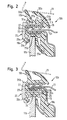
- Fig. 2 shows a section along the line A-A in Fig. 1.
- the sealing profile 10b has a one-piece base body 18 which is extruded from an elastomeric material, for example EPDM.
- a fastening region 20 is formed, in which a flexible reinforcing element 27 is introduced.
- the attachment area 20 serves to fix the sealing profile 10 b to a door flange 21.
- the sealing profile 10b has a first sealing area 19a, which serves to seal the movable window pane 11b.
- sealing lips 29a, 29b, 29c are provided, which bear against the outside of the window pane 11b.
- the sealing lips 29a, 29b, 29c are each provided with a flocking.
- a second sealing area 19b is provided on the base body 18, which serves to seal the vehicle door 12b relative to the body 13.
- the second sealing region 19b has sealing lips 30a, 30b, which are each provided with an outside flocking.
- a decorative strip 22 is fixed, which is designed as Aluminiumstrangpreßprofil.
- the trim strip 22 is formed bent according to the course of the vehicle line.
- the trim strip 22 has an externally visible aperture region 23, from which a fastening element 24 protrudes substantially perpendicularly.
- the fastening element 24 is designed as an elongated insertion blade. From the fastener project peg-like projections 25a, 25b.
- the base body 18 has a slot-shaped receiving channel 28, on the receptacles 31 a, 31 b for receiving the lugs 25 a, 25 b are formed.
- the receiving channel 28 is arranged above the door flange 21.
- the protruding from an upper portion of the trim strip 22 fastener 24 is used in the bending of the trim strip 22 according to the course of the vehicle line as a support for the bending process.
- a secure fixing is achieved by the design of the fastener 24 as a long insertion blade, which prevents tilting and twisting of the diaphragm portion 23 of the trim strip 22.
- a projection 26a is provided on the end, which is fixed in a form-fitting manner to an associated receptacle of the base body 18.
- the fastening region 20 of the main body 18 is first pushed onto the door flange 21. Subsequently, the trim strip 22 is inserted with the fastening element 24 in the receiving channel 28. Then, the sealing portion 19b is fixed to the fixing member 24.
- Fig. 3 shows a further embodiment, for the description of which the already introduced reference numerals are used for identical or functionally identical parts.
- the sealing profile 10b shown in Fig. 3 differs only by the different configuration of the trim strip 22.
- the mounting portion 24 protrudes from a central region of the aperture portion 23 of the trim strip 22 from.
- the fastening element 24 is designed as an elongated insertion blade, the end has a pin-like projection 25b.
- the fastening element 24 is received in a slot-shaped receiving channel 28 of the main body 18.
- the arrangement of the fastener 24 and the receiving channel 28 causes the fastener 24 is positioned in the assembled state of the trim strip 22 below the door flange 21.
- the end regions of the diaphragm region 23 are formed with lugs 26a, 26b, which are accommodated in form-fitting receptacles of the base body 18.
- the fastener 24 as an elongated Einsteckhist that this serves as a support for the bending operation of the trim strip 22.
- Fig. 4 shows the sealing profile 10b prior to assembly of the trim strip 22.
- the receiving channel 28 is the end with a coextruded tear-off 32nd closed, which is connected via webs 33 a, 33 b to the base body 18.
- the tear-off cord prevents contamination of the receiving channel 28.
- the webs 33a, 33b are severed, whereby the receiving channel 28 is released.
Landscapes
- Engineering & Computer Science (AREA)
- Mechanical Engineering (AREA)
- Seal Device For Vehicle (AREA)
Description
- Die vorliegende Erfindung betrifft ein Dichtungsprofil zum Abdichten einer beweglichen Fensterscheibe in einer Kraftfahrzeugtür mit einem aus einem elastischen Material hergestellten Grundkörper, in dem mindestens ein Dichtungsbereich und mindestens ein Befestigungsbereich zur Festlegung des Dichtungsprofils an einem Türflansch vorgesehen ist, und mit mindestens einer Zierleiste, die einen Blendenbereich und ein hiervon abragendes Befestigungselement aufweist, das formschlüssig an dem Grundkörper festlegbar ist.
- Ein derartiges Dichtungsprofil ist aus der
DE 197 36 899 C2 bekannt. Das Dichtungsprofil dient zum Abdichten eines Fensterschachts in einer Kraftfahrzeugtür. Die Zierblende weist ein von dem Blendenbereich abragendes Befestigungselement auf, das bei der Montage des Dichtungsprofils am Fahrzeug formschlüssig von einem schwenkbeweglich angeordneten Haltebereich des Dichtungsprofils umfasst wird. - Aus der
DE 199 22 749 A1 ist ein anderes Dichtungsprofil bekannt, das einerseits zur Abdichtung einerbeweglichen Fensterscheibe und andererseits zur Abdichtung des Türspalts ausgebildet ist. Eine außenseitig aufgebrachte Zierleiste wird mittels U-förmigen Halteklammern an dem Grundkörper des Dichtungsprofils festgelegt. - Eine Dichtungsanordnung für die Tür eines Kraftfahrzeugs, die zum Abdichten eines eine Fensterscheibe aufnehmenden Schachts dient, wird in der
WO 01/87658 A1 - Eine Dichtungsanordnung zum Abdichten der Fensterscheibe eines Kraftfahrzeugs offenbart außerdem die
EP 1 232 887 A2 . Die Dichtungsanordnung weist eine die Oberkante der Fensterscheibe abdichtende Dichtung auf, an der eine Zierleiste befestigt ist. Die Zierleiste ist direkt auf einen Flansch des Kraftfahrzeugs aufgesteckt. - Der Erfindung liegt die Aufgabe zugrunde ein Dichtungsprofil vorzuschlagen, bei dem die Zierleiste in einfacher und sicherer Weise festlegbar ist.
- Diese Aufgabe wird durch ein Dichtungsprofil gemäß Anspruch 1 gelöst. Bevorzugte Ausgestaltungen eines solchen Dichtungsprofils werden in den Ansprüchen 2 bis 8 definiert.
- Das als Einsteckschwert ausgebildete Befestigungselement dient als Auflage für den Biegevorgang der Zierleiste. Weiterhin verhindert das im Wesentlichen senkrecht zu dem Blendenbereich ausgerichteten Befestigungselement ein Kippen des Blendenbereichs. Darüber hinaus wird eine tordierte Lage durch die vorgesehene Befestigung der Zierleiste ausgeschlossen. Schließlich ist die Herstellung und Montage sehr einfach, da zur Festlegung der Zierleiste keine zusätzlichen Teile, beispielsweise Klammern, erforderlich sind.
- In dem Grundkörper ist ein schlitzförmiger Aufnahmekanal zur Aufnahme des Befestigungselements eingebracht. Bei der Montage der Zierleiste an dem Grundkörper wird das Befestigungselement in den schlitzförmigen Aufnahmekanal eingebracht und hierin formschlüssig festgelegt. Der Befestigungsbereich weist ein Verstärkungselement auf, das flexibel ausgebildet ist.
- Der Grundkörper weist einen ersten Dichtungsbereich zum Abdichten der beweglichen Fensterscheibe und einen zweiten Dichtungsbereich zur Abdichtung des Türspalts auf. Der erste Dichtungsbereich weist Dichtlippen auf, die von dem Grundkörper abragen und an der beweglichen Fensterscheibe anliegen. Zur Abdichtung des Türspalts weist der zweite Dichtungsbereich Dichtlippen auf, die von dem Grundkörper abragen und an der Fahrzeugkarosserie anliegen.
- Vorteilhaft ist die Zierleiste als stranggepresstes Aluminiumteil ausgebildet.
- Nach einer vorteilhaften Ausgestaltung ragt das Befestigungselement von einem oben liegenden Endbereich des Blendenbereichs ab. In montiertem Zustand der Zierleiste ist somit das Befestigungselement oberhalb des Türflanschs angeordnet.
- Bei einer anderen vorteilhaften Ausgestaltung ragt das Befestigungselement von einem mittleren Bereich des Blendenbereichs ab. Somit ist das Befestigungselement in montiertem Zustand der Zierleiste unterhalb des Türflanschs angeordnet.
- Vorteilhaft sind an dem Blendenbereich Ansätze ausgebildet, die in zugeordneten Aufnahmen an dem Grundkörper eingreifen. Hierdurch wird eine formschlüssige Fixierung des Blendenbereichs an dem Grundkörper erzielt.
- Vorteilhaft weisen die Dichtlippen eine außenseitige Beflockung auf.
- Nachfolgend wird die Erfindung an Hand von Ausführungsbeispielen näher beschrieben, die in den Zeichnungen in schematischer Weise dargestellt sind. Hierin zeigen:
- Fig. 1
- eine schematische Seitenansicht eines Fahrzeugs mit einem erfindungsgemäßen Dichtungsprofil;
- Fig. 2
- einen Schnitt längs der Linie A-A in Fig. 1 bei einer ersten erfindungsgemäßen Ausführungsform;
- Fig. 3
- einen Schnitt längs der Linie A-A in Fig. 1 bei einer zweiten erfindungsgemäßen Ausführungsform und
- Fig. 4
- einen Teilschnitt durch das in Fig. 2 dargestellte Dichtungsprofil mit einer einen Aufnahmekanal endseitig verschließenden Abreißschnur.
- Fig. 1 zeigt die Seitenansicht eines Kraftfahrzeugs, das eine Vordertür 12a und eine Hintertür 12b aufweist, in denen jeweils eine bewegliche Fensterscheibe 11a, 11 b angeordnet ist, die in dem Türschacht der jeweiligen Tür 12a, 12b versenkbar ist. Zur Abdichtung der Fensterscheibe 11a, 11b sowie der Tür 12a, 12b gegenüber der Karosserie 13 ist an jeder Fahrzeugtür 12a, 12b ein Dichtungsprofil 10a, 10b vorgesehen. Das Dichtungsprofil 10a der Vordertür 12a erstreckt sich von einer Vorderkante 17 der Fahrzeugtür 12a bis zu der B-Säule 14 des Fahrzeugs. Das Dichtungsprofil 10b der Hintertür 12b erstreckt sich von der B-Säule 14 bis zu einer Hinterkante 16 der Fahrzeugtür 12b. Im Bereich der B-Säule 14 sind die Dichtungsprofile 10a, 10b getrennt, da hier der die Türen 12a, 12b trennende Spalt 15 verläuft.
- Fig. 2 zeigt einen Schnitt längs der Linie A-A in Fig. 1. Das Dichtungsprofil 10b weist einen einteiligen Grundkörper 18 auf, der aus einem elastomeren Material, beispielsweise EPDM, extrudiert ist. An dem Grundkörper 18 ist ein Befestigungsbereich 20 ausgebildet, in dem ein flexibles Verstärkungselement 27 eingebracht ist. Der Befestigungsbereich 20 dient der Festlegung des Dichtungsprofils 10b an einem Türflansch 21.
- Das Dichtungsprofil 10b weist einen ersten Dichtungsbereich 19a auf, der der Abdichtung der beweglichen Fensterscheibe 11b dient. An dem Dichtungsprofil 19a sind Dichtlippen 29a, 29b, 29c vorgesehen, die an der Außenseite der Fensterscheibe 11b anliegen. Die Dichtlippen 29a, 29b, 29c sind jeweils mit einer Beflockung versehen. Weiterhin ist an dem Grundkörper 18 ein zweiter Dichtungsbereich 19b vorgesehen, der der Abdichtung der Fahrzeugtür 12b gegenüber der Karosserie 13 dient. Der zweite Dichtungsbereich 19b weist Dichtlippen 30a, 30b auf, die jeweils mit einer außenseitigen Beflockung versehen sind.
- An dem Grundkörper 18 ist eine Zierleiste 22 festgelegt, die als Aluminiumstrangpreßprofil ausgebildet ist. Wie aus Fig. 1 ersichtlich ist, ist die Zierleiste 22 entsprechend dem Verlauf der Fahrzeuglinie gebogen ausgebildet. Die Zierleiste 22 weist einen von außen sichtbaren Blendenbereich 23 auf, von dem im wesentlichen senkrecht ein Befestigungselement 24 abragt. Das Befestigungselement 24 ist als längliches Einsteckschwert ausgebildet. Von dem Befestigungselement ragen zapfenartige Ansätze 25a, 25b ab. Zur formschlüssigen Aufnahme des Befestigungselements 24 weist der Grundkörper 18 einen schlitzförmigen Aufnahmekanal 28 auf, an dem Aufnahmen 31 a, 31b zur Aufnahme der Ansätze 25a, 25b eingeformt sind. Der Aufnahmekanal 28 ist oberhalb des Türflanschs 21 angeordnet. Somit ist auch das Befestigungselement 24 in montiertem Zustand der Zierleiste oberhalb des Türflanschs 21 positioniert.
- Das von einem oberen Bereich der Zierleiste 22 abragende Befestigungselement 24 dient bei der Biegung der Zierleiste 22 entsprechend dem Verlauf der Fahrzeuglinie als Stütze für den Biegevorgang. Darüber hinaus wird durch die Ausgestaltung des Befestigungselements 24 als langes Einsteckschwert eine sichere Festlegung erzielt, die ein Kippen und Tordieren des Blendenbereichs 23 der Zierleiste 22 verhindert.
- An dem Blendenbereich 23 ist endseitig ein Ansatz 26a vorgesehen, der formschlüssig an einer zugeordneten Aufnahme des Grundkörpers 18 festgelegt ist.
- Bei der Montage des Dichtungsprofils 10b wird zunächst der Befestigungsbereich 20 des Grundkörpers 18 auf den Türflansch 21 aufgesteckt. Nachfolgend wird die Zierleiste 22 mit dem Befestigungselement 24 in den Aufnahmekanal 28 eingesteckt. Dann wird der Dichtungsbereich 19b an dem Befestigungselement 24 festgelegt.
- In der dargestellten Endstellung wird eine sichere Fixierung der Zierleiste 22 an dem Grundkörper 18 erzielt.
- Fig. 3 zeigt eine weitere Ausführungsform, zu deren Beschreibung die bereits eingeführten Bezugszeichen für gleiche oder funktionsgleiche Teile verwendet werden. Das in Fig. 3 dargestellte Dichtungsprofil 10b unterscheidet sich lediglich durch die abweichende Ausgestaltung der Zierleiste 22. Hierbei ragt der Befestigungsbereich 24 von einem mittleren Bereich des Blendenbereichs 23 der Zierleiste 22 ab. Das Befestigungselement 24 ist als langgestrecktes Einsteckschwert ausgebildet, das endseitig einen zapfenartigen Ansatz 25b aufweist. Das Befestigungselement 24 ist in einem schlitzförmigen Aufnahmekanal 28 des Grundkörpers 18 aufgenommen. Die Anordnung des Befestigungselements 24 und des Aufnahmekanals 28 bewirkt, daß das Befestigungselement 24 in montiertem Zustand der Zierleiste 22 unterhalb des Türflanschs 21 positioniert ist.
- Die Endbereiche des Blendenbereichs 23 sind mit Ansätzen 26a, 26b ausgebildet, die in formschlüssigen Aufnahmen des Grundkörpers 18 aufgenommen sind.
- Auch bei dieser Ausführungsform gestattet die Ausbildung des Befestigungselements 24 als langgestrecktes Einsteckschwert, daß dieses als Stütze für den Biegevorgang der Zierleiste 22 dient. Darüber hinaus verhindert das sich bis in die Tiefe des Grundkörpers 18 erstreckende Befestigungselement 24 ein Kippen des Blendenbereichs 23 der Zierleiste 22.
- In prinzipiell ähnlicher Weise wie bei der Ausführungsform gemäß Fig. 2 erfolgt bei der Ausführungsform gemäß Fig. 3 zunächst die Montage des Grundkörpers 18 an dem Türflansch 21. Nachfolgend wird die Zierleiste 22 mit dem im wesentlichen senkrecht abragenden Befestigungselement 24 in den schlitzförmigen Aufnahmekanal 28 des Grundkörpers 18 eingebracht. Hierbei erfolgt eine formschlüssige Festlegung an dem Grundkörper 18.
- Fig. 4 zeigt das Dichtungsprofil 10b vor der Montage der Zierleiste 22. Der Aufnahmekanal 28 ist endseitig mit einer koextrudierten Abreißschnur 32 verschlossen, die über Stege 33a, 33b mit dem Grundkörper 18 verbunden ist. Die Abreißschnur verhindert eine Verschmutzung des Aufnahmekanals 28. Beim Abziehen der Abreißschnur 32 werden die Stege 33a, 33b durchtrennt, wodurch der Aufnahmekanal 28 freigegeben wird.
- Allen vorstehend beschriebenen Ausführungsformen ist gemeinsam, daß durch die erfindungsgemäße Ausgestaltung der Zierleiste eine einfache Herstellung und Montage gewährleistet ist.
-
- 10a,b
- Dichtungsprofil
- 11 a,b
- Fensterscheibe
- 12a,b
- Fahrzeugtür
- 13
- Karosserie
- 14
- B-Säule
- 15
- Spalt
- 16
- Hinterkante
- 17
- Vorderkante
- 18
- Grundkörper
- 19a,b
- Dichtungsbereich
- 20
- Befestigungsbereich
- 21
- Türflansch
- 22
- Zierleiste
- 23
- Blendenbereich
- 24
- Befestigungselement
- 25 a, b
- Ansatz
- 26 a, b
- Ansatz
- 27
- Verstärkungselement
- 28
- Aufnahmekanal
- 29 a, b, c
- Dichtlippe
- 30 a, b
- Dichtlippe
- 31 a, b
- Aufnahme
- 32
- Abreißschnur
- 33 a,b
- Steg
Claims (8)
- Dichtungsprofil (10a, 10b) zum Abdichten einer beweglichen Fensterscheibe (11 a, 11 b) in einer Tür (12a, 12b) eines Kraftfahrzeugs mit einem Grundkörper (18), dera) aus einem elastischen Material hergestellt ist undb) einen ersten Dichtungsbereich (19a), der zum Abdichten der Fensterscheibe (11a, 11 b) mit Dichtlippen (29a, 29b, 29c) versehen ist, die von dem Grundkörper (18) abragen und an der Fensterscheibe (11a, 11 b) anliegen,c) einen zweiten Dichtungsbereich (19b), der zum Abdichten der Tür (12a, 12b) gegenüber der Karosserie (13) des Kraftfahrzeugs mit Dichtlippen (30a, 30b) versehen ist, die von dem Grundkörper (18) abragen und an der Karosserie (13) des Kraftfahrzeugs anliegen,d) einen Befestigungsbereich (20), der zum Befestigen des Dichtungsprofils (10a, 10b) an einem Türflansch (21) festlegbar ist,e) ein flexibles Verstärkungselement (27), das den Befestigungsbereich (20) im Bereich des Türflansches (21) verstärkt und einen im Wesentlichen parallel zu dem Türflansch (21) verlaufenden Schenkel aufweist, undf) einen schlitzförmigen Aufnahmekanal (28), der sich entlang des Schenkels des Verstärkungselements (27) erstreckt und mit wenigstens einer Aufnahme (31a, 31b) versehen ist, umfasst, und einer Zierleiste (22), diea) in ihrer Längsrichtung gebogen ist,b) einen Blendenbereich (23) umfasst undc) ein Befestigungselement (24), das als längliches, im Wesentlichen senkrecht zu dem Blendenbereich (23) ausgerichtetes Einsteckschwert ausgebildet und mit mindestens einem Ansatz (25a, 25b) versehen ist, umfasst;wobei das Befestigungselement (24) derart in dem Aufnahmekanal (28) angeordnet ist, dass der Ansatz (25a, 25b) des Befestigungselements (24) formschlüssig in die zugeordnete Aufnahme (31a, 31b) des Aufnahmekanals (28) eingreift und
wobei der Grundkörper (18) in dem Bereich, der sich auf der Seite des Befestigungselements (24), die dem Schenkel des Verstärkungselements (27) abgewandt ist, befindet, frei von dem Verstärkungselement (27) ist. - Dichtungsprofil nach Anspruch 1, dadurch gekennzeichnet, dass das Verstärkungselement (27) im Querschnitt im wesentlichen U-förmig ist.
- Dichtungsprofil nach Anspruch 1 oder 2, dadurch gekennzeichnet, dass die Zierleiste (22) ein stranggepresstes Aluminiumteil ist.
- Dichtungsprofil nach einem der Ansprüche 1 bis 3, dadurch gekennzeichnet, dass die Zierleiste (22) im Querschnitt im Wesentlichen L-förmig ist, wobei das Befestigungselement (24) von einem oben liegenden Endbereich des Blendenbereichs (23) abragt.
- Dichtungsprofil nach einem der Ansprüche 1 bis 3, dadurch gekennzeichnet, dass die Zierleiste (22) im Querschnitt im Wesentlichen T-förmig ist, wobei das Befestigungselement (24) von einem mittleren Bereich des Blendenbereichs (23) abragt.
- Dichtungsprofil nach einem der Ansprüche 1 bis 5, dadurch gekennzeichnet, dass an dem Blendenbereich Ansätze (26a, 26b) ausgebildet sind, die in zugeordnete Aufnahmen an dem Grundkörper (18) eingreifen.
- Dichtungsprofil nach einem der Ansprüche 1 bis 6, dadurch gekennzeichnet, dass der Aufnahmekanal (28) vor der Montage der Zierleiste (22) durch eine Abreißschnur (32), die über Stege (33a, 33b) mit dem Grundkörper (18) verbunden ist, verschlossen ist.
- Dichtungsprofil nach einem der Ansprüche 1 bis 7, dadurch gekennzeichnet, dass der Aufnahmekanal (28) entweder zwischen dem Befestigungsbereich (20) und dem ersten Dichtungsbereich (19a) oder zwischen dem Befestigungsbereich (20) und dem zweiten Dichtungsbereich (19b) angeordnet ist.
Priority Applications (1)
| Application Number | Priority Date | Filing Date | Title |
|---|---|---|---|
| DE20321018U DE20321018U1 (de) | 2002-10-09 | 2003-10-09 | Dichtungsprofil mit Zierleiste |
Applications Claiming Priority (3)
| Application Number | Priority Date | Filing Date | Title |
|---|---|---|---|
| DE10247015 | 2002-10-09 | ||
| DE10247015A DE10247015B4 (de) | 2002-10-09 | 2002-10-09 | Dichtungsprofil mit Zierleiste |
| PCT/EP2003/011208 WO2004037576A2 (de) | 2002-10-09 | 2003-10-09 | Dichtungsprofil mit zierleiste |
Publications (2)
| Publication Number | Publication Date |
|---|---|
| EP1549520A2 EP1549520A2 (de) | 2005-07-06 |
| EP1549520B1 true EP1549520B1 (de) | 2008-01-16 |
Family
ID=32038366
Family Applications (1)
| Application Number | Title | Priority Date | Filing Date |
|---|---|---|---|
| EP03809275A Expired - Lifetime EP1549520B1 (de) | 2002-10-09 | 2003-10-09 | Dichtungsprofil mit zierleiste |
Country Status (9)
| Country | Link |
|---|---|
| US (1) | US7478863B2 (de) |
| EP (1) | EP1549520B1 (de) |
| CN (1) | CN100379595C (de) |
| AU (1) | AU2003296557A1 (de) |
| BR (1) | BR0315073B1 (de) |
| DE (2) | DE10247015B4 (de) |
| ES (1) | ES2299757T3 (de) |
| MX (1) | MXPA05003769A (de) |
| WO (1) | WO2004037576A2 (de) |
Cited By (1)
| Publication number | Priority date | Publication date | Assignee | Title |
|---|---|---|---|---|
| WO2014188004A1 (de) | 2013-05-24 | 2014-11-27 | Cooper Standard GmbH | Dichtungsanordnung sowie zierleiste und trägerprofil für eine dichtungsanordnung |
Families Citing this family (44)
| Publication number | Priority date | Publication date | Assignee | Title |
|---|---|---|---|---|
| GB2419371A (en) * | 2004-10-20 | 2006-04-26 | Gdx Automotive Rehburg Gmbh & | Sealing, trimming or guiding strips |
| GB2429027A (en) * | 2005-08-12 | 2007-02-14 | Gdx North America Inc | Window sealing and guiding arrangements |
| US8051607B2 (en) * | 2005-11-09 | 2011-11-08 | Toyoda Gosei Co., Ltd. | Weather strip and manufacturing method thereof |
| JP5032789B2 (ja) * | 2006-05-01 | 2012-09-26 | 鬼怒川ゴム工業株式会社 | パーティングシール |
| DE102006021190B4 (de) * | 2006-05-06 | 2008-08-14 | GM Global Technology Operations, Inc., Detroit | Dichtungsprofil |
| DE102006053094A1 (de) * | 2006-11-10 | 2008-05-15 | Metzeler Automotive Profile Systems Gmbh | Dichtung und Dichtungsanordnung zum Abdichten von Fensterscheiben eines Kraftfahrzeugs |
| KR100892694B1 (ko) * | 2006-11-17 | 2009-04-15 | 현대자동차주식회사 | 차량용 도어 프레임 |
| GB2445614A (en) * | 2007-01-10 | 2008-07-16 | Gdx North America Inc | A sealing and guiding assembly for a window. |
| DE602007000723D1 (de) * | 2007-01-12 | 2009-04-30 | Rainforest R & D Ltd | Befestigungsleiste zur Verwendung mit einer Abdichtung zum Abdichten eines Fensters einer Fahrzeugtür |
| FR2911628A1 (fr) * | 2007-01-22 | 2008-07-25 | Metzeler Automotive Profile | Ensemble profil de joint et profile, notamment pour element d'ouvrant de vehicule automobile, et element d'ouvrant obtenu |
| DE102008026046A1 (de) | 2008-05-27 | 2009-12-03 | SaarGummi technologies S.à.r.l. | Dichtungsstrang mit Zierleiste |
| US8166708B2 (en) * | 2008-07-30 | 2012-05-01 | Ellis Peter J | Integrated glass run and upper reveal with film |
| EP2346707A4 (de) * | 2008-10-24 | 2015-10-21 | Cooper Standard Automotive Inc | Fensterglasführung mit applikationsanordnung |
| GB0914571D0 (en) | 2009-08-20 | 2009-09-30 | Pilkington Group Ltd | Vehicle glazing |
| US8322078B2 (en) * | 2010-01-13 | 2012-12-04 | Ford Global Technologies, Llc | Inner panel design for automotive door header |
| DE102010001468B4 (de) | 2010-02-01 | 2014-01-23 | Draftex Automotive Gmbh | Verfahren zur Herstellung einer Dichtung |
| DE102010026669A1 (de) | 2010-07-09 | 2012-01-12 | Daimler Ag | Verfahren zur Montage eines Strangprofils |
| US20120025564A1 (en) * | 2010-07-28 | 2012-02-02 | Magna International Inc. | Flush Glass System Module |
| DE102010039774A1 (de) | 2010-08-25 | 2012-03-01 | Metzeler Automotive Profile Systems Gmbh | Dichtungsanordnung für ein Kraftfahrzeug, insbesondere zum Abdichten und Führen einer bewegbaren Fensterscheibe |
| WO2012121877A1 (en) * | 2011-03-10 | 2012-09-13 | Boston Scientific Scimed, Inc. | Flexible suturing instrument |
| DE102011014540A1 (de) * | 2011-03-19 | 2012-09-20 | Audi Ag | Profildichtung mit Zierleiste für ein Fahrzeug |
| CN102211552B (zh) * | 2011-04-25 | 2013-03-13 | 宁波信泰机械有限公司 | 一种后三角窗亮条的制造方法 |
| JP5610308B2 (ja) * | 2011-09-27 | 2014-10-22 | 豊田合成株式会社 | ガラスラン |
| DE102012103833A1 (de) * | 2012-05-02 | 2013-11-07 | Dr. Ing. H.C. F. Porsche Aktiengesellschaft | Befestigungseinrichtung |
| US8919846B2 (en) | 2012-05-04 | 2014-12-30 | Srg Global, Inc. | Daylight opening system for vehicle |
| US9114693B2 (en) * | 2012-05-04 | 2015-08-25 | Srg Global, Inc. | Daylight opening system |
| CN103395355A (zh) * | 2013-08-07 | 2013-11-20 | 宁波敏实汽车零部件技术研发有限公司 | 一种汽车门框上装饰密封条 |
| CN103692890B (zh) * | 2013-12-13 | 2016-04-27 | 宁波信泰机械有限公司 | 一种汽车窗台外侧密封条 |
| US9290083B2 (en) * | 2013-12-18 | 2016-03-22 | Ford Global Technologies, Llc | Glass sealing system |
| US9079480B1 (en) * | 2014-06-06 | 2015-07-14 | Toyota Motor Engineering & Manufacturing North America, Inc. | Glass run weather strip assembly |
| US9327769B2 (en) | 2014-09-05 | 2016-05-03 | Toyota Motor Engineering & Manufacturing North America, Inc. | Vehicles having internal body cavity seals and methods of assembling the same |
| JP6566744B2 (ja) * | 2015-06-30 | 2019-08-28 | 西川ゴム工業株式会社 | 自動車用ドアのシール材 |
| JP6566745B2 (ja) * | 2015-06-30 | 2019-08-28 | 西川ゴム工業株式会社 | 自動車用ドアのシール材 |
| JP6512966B2 (ja) * | 2015-07-01 | 2019-05-15 | 西川ゴム工業株式会社 | モールの取付構造 |
| JP6585952B2 (ja) * | 2015-07-28 | 2019-10-02 | 西川ゴム工業株式会社 | 自動車ドア用モールの取付構造 |
| US10661643B1 (en) * | 2016-05-05 | 2020-05-26 | Cooper-Standard Automotive Inc. | Bright strip retention clip assembly |
| US20170355254A1 (en) * | 2016-06-08 | 2017-12-14 | Hyundai Motor Company | Sealing structure of a door frame |
| JP6936559B2 (ja) * | 2016-06-20 | 2021-09-15 | 西川ゴム工業株式会社 | 自動車ドア用グラスラン |
| DE102018110218A1 (de) * | 2017-06-12 | 2018-12-13 | Cqlt Saargummi Technologies S.À.R.L. | Dichtungsanordnung zur Führung und Abdichtung einer vertikal bewegbaren Fahrzeugfensterscheibe |
| JP7137409B2 (ja) * | 2018-09-06 | 2022-09-14 | 西川ゴム工業株式会社 | 自動車ドア用シール構造 |
| CN110884241B (zh) * | 2019-12-27 | 2024-03-08 | 江阴海达橡塑股份有限公司 | 一种汽车密封胶条的助剥纸热烫装置及其热烫方法 |
| DE102020113445A1 (de) * | 2020-05-18 | 2021-04-29 | Audi Aktiengesellschaft | Fensterführungsdichtung |
| JP7403399B2 (ja) * | 2020-07-02 | 2023-12-22 | 西川ゴム工業株式会社 | 自動車ドア用グラスラン |
| JP2025040271A (ja) * | 2023-09-11 | 2025-03-24 | 西川ゴム工業株式会社 | 自動車ドア用グラスラン |
Family Cites Families (19)
| Publication number | Priority date | Publication date | Assignee | Title |
|---|---|---|---|---|
| DE3442241A1 (de) * | 1984-11-19 | 1986-05-28 | Metzeler Kautschuk GmbH, 8000 München | Vorrichtung zur gleichzeitigen abdichtung der tuerscheibe und des dachbereiches einer kraftfahrzeug-tuer |
| JP2865832B2 (ja) * | 1990-08-31 | 1999-03-08 | 鬼怒川ゴム工業株式会社 | ウエザーストリップの取付構造 |
| JP2648767B2 (ja) * | 1990-11-28 | 1997-09-03 | 豊田合成株式会社 | ガラスランの取付構造 |
| DE4339033C2 (de) * | 1993-11-15 | 1997-08-21 | Metzeler Automotive Profiles | Anordnung zum gleichzeitigen Abdichten einer Türscheibe und der Türöffnung an einem Kraftfahrzeug |
| GB2285471B (en) * | 1994-01-11 | 1997-02-12 | Draftex Ind Ltd | Sealing or guiding assemblies and methods of making them |
| JPH08142672A (ja) * | 1994-11-15 | 1996-06-04 | Nishikawa Rubber Co Ltd | ドアオープニングウエザーストリップ |
| DE19736899C2 (de) * | 1997-08-25 | 2000-05-18 | Metzeler Automotive Profiles | Dichtungsprofil für Kraftfahrzeuge |
| DE19845422A1 (de) * | 1998-10-02 | 2000-04-20 | Metzeler Automotive Profiles | Dichtungsanordnung |
| DE19922749B4 (de) * | 1999-05-18 | 2004-11-11 | Bayerische Motoren Werke Ag | Dichtung für eine Fensterscheibe |
| US6409251B1 (en) * | 1999-05-27 | 2002-06-25 | Schlegel Corporation | Glass run surround cap |
| DE19938258B4 (de) * | 1999-08-12 | 2008-08-28 | Volkswagen Ag | Fahrzeugtür mit einer Fensterschachtabdichtung |
| DE60021910T2 (de) * | 1999-11-12 | 2006-04-06 | Gdx North America Inc., Dover | Fensterdichtungsanordnung mit t-förmigem verkleidungselement |
| US6370824B1 (en) * | 2000-05-10 | 2002-04-16 | Hutchinson Sealing Systems, Inc. | Automotive vehicle seal with decorative trim sealing surface |
| GB2362415B (en) * | 2000-05-15 | 2004-08-25 | Draftex Ind Ltd | Sealing,trimming and finishing strips and vehicle doors incorporating such strips |
| EP1232887B1 (de) * | 2001-02-15 | 2007-04-18 | Toyoda Gosei Co., Ltd. | Türzarge für Kraftfahrzeuge |
| DE10134465C1 (de) * | 2001-07-16 | 2002-12-05 | Metzeler Automotive Profile | Dichtung, insbesondere zum Abdichten einer in einer Kraftfahrzeugtür verschiebbar angeordneten Fensterscheibe |
| US6652952B2 (en) * | 2001-07-23 | 2003-11-25 | Cooper Technology Services, Llc | Extrusion having thermoplastic elastomer co-extruded on core with additional ionomeric show surface |
| ATE391625T1 (de) * | 2002-10-02 | 2008-04-15 | Gdx North America Inc | Dichtungs-, zier- oder führungsstreifen |
| JP4809119B2 (ja) * | 2006-05-12 | 2011-11-09 | 西川ゴム工業株式会社 | ガラスランの取付構造 |
-
2002
- 2002-10-09 DE DE10247015A patent/DE10247015B4/de not_active Expired - Lifetime
-
2003
- 2003-10-09 WO PCT/EP2003/011208 patent/WO2004037576A2/de not_active Ceased
- 2003-10-09 MX MXPA05003769A patent/MXPA05003769A/es active IP Right Grant
- 2003-10-09 DE DE50309039T patent/DE50309039D1/de not_active Expired - Lifetime
- 2003-10-09 ES ES03809275T patent/ES2299757T3/es not_active Expired - Lifetime
- 2003-10-09 CN CNB2003801010782A patent/CN100379595C/zh not_active Expired - Fee Related
- 2003-10-09 EP EP03809275A patent/EP1549520B1/de not_active Expired - Lifetime
- 2003-10-09 AU AU2003296557A patent/AU2003296557A1/en not_active Abandoned
- 2003-10-09 BR BRPI0315073-9A patent/BR0315073B1/pt not_active IP Right Cessation
- 2003-10-09 US US10/530,735 patent/US7478863B2/en not_active Expired - Lifetime
Cited By (1)
| Publication number | Priority date | Publication date | Assignee | Title |
|---|---|---|---|---|
| WO2014188004A1 (de) | 2013-05-24 | 2014-11-27 | Cooper Standard GmbH | Dichtungsanordnung sowie zierleiste und trägerprofil für eine dichtungsanordnung |
Also Published As
| Publication number | Publication date |
|---|---|
| DE10247015B4 (de) | 2005-02-03 |
| WO2004037576A2 (de) | 2004-05-06 |
| US20080030046A1 (en) | 2008-02-07 |
| AU2003296557A1 (en) | 2004-05-13 |
| BR0315073B1 (pt) | 2009-08-11 |
| US7478863B2 (en) | 2009-01-20 |
| ES2299757T3 (es) | 2008-06-01 |
| DE10247015A1 (de) | 2004-04-22 |
| DE50309039D1 (de) | 2008-03-06 |
| CN1703331A (zh) | 2005-11-30 |
| PL377691A1 (pl) | 2006-02-06 |
| AU2003296557A8 (en) | 2004-05-13 |
| WO2004037576A3 (de) | 2004-05-27 |
| EP1549520A2 (de) | 2005-07-06 |
| MXPA05003769A (es) | 2006-01-30 |
| BR0315073A (pt) | 2005-08-16 |
| CN100379595C (zh) | 2008-04-09 |
Similar Documents
| Publication | Publication Date | Title |
|---|---|---|
| EP1549520B1 (de) | Dichtungsprofil mit zierleiste | |
| DE4339033C2 (de) | Anordnung zum gleichzeitigen Abdichten einer Türscheibe und der Türöffnung an einem Kraftfahrzeug | |
| EP1920963B1 (de) | Dichtungsanordnung zum Abdichten von beweglichen KFZ-Fensterscheiben | |
| DE69508132T2 (de) | Dichtungsleisteanordnung | |
| EP1211116B1 (de) | Dichtungsprofil | |
| EP1572482A1 (de) | Dichtungsanordnung, insbesondere zum abdichten von fensterscheiben eines kraftfahrzeugs | |
| EP1131220B2 (de) | Fensterdichtungsprofil für ein kabriolett | |
| DE10052739A1 (de) | Kraftfahrzeugtür | |
| DE69200265T2 (de) | Dichtungszierleiste für das Einfassen einer beweglichen Kraftfahrzeugscheibe. | |
| DE19639280A1 (de) | Kraftfahrzeugtür | |
| EP0596306A2 (de) | Abdeckleiste für eine in ein Fahrzeugdach eingelassene Rinne | |
| DE69004387T2 (de) | Streifenanordnung für Kraftfahrzeuge. | |
| WO2003008221A1 (de) | Dichtung, insbesondere zum abdichten einer in einer kraftfahrzeugtür verschiebbar angeordneten fensterscheibe | |
| EP2335959A1 (de) | Dichtung zum Abdichten eines Fensterschachts eines Kraftfahrzeugs | |
| DE102006021190A1 (de) | Dichtungsprofil | |
| DE10258825B3 (de) | Dichtungsanordnung, insbesondere zum Abdichten und Führen einer Fensterscheibe eines Kraftfahrzeugs | |
| DE102005043950B4 (de) | Fensterschachtleiste für die Tür eines Kraftfahrzeuges | |
| EP0872369A1 (de) | Kurbelfenster in einer Fahrzeugtür | |
| DE29712859U1 (de) | Kraftfahrzeug mit relativ zueinander verschieblichen Fensterscheiben | |
| WO2024240377A1 (de) | Dichtungsprofil und anordnung des dichtungsprofils zwischen einer brüstung und einer fensterscheibe im dichtungsfreien design | |
| DE29807479U1 (de) | Türmodul für eine Fahrzeugtür | |
| EP0877670A1 (de) | Kraftfahrzeug-dichtungsprofil | |
| DE10230682B4 (de) | Dichtungsanordnung zum Abdichten eines Spalts, insbesondere an einem Kraftfahrzeug | |
| DE20321018U9 (de) | Dichtungsprofil mit Zierleiste | |
| DE3425687A1 (de) | Fuer ein kraftfahrzeug bestimmtes schwenkfenster |
Legal Events
| Date | Code | Title | Description |
|---|---|---|---|
| PUAI | Public reference made under article 153(3) epc to a published international application that has entered the european phase |
Free format text: ORIGINAL CODE: 0009012 |
|
| 17P | Request for examination filed |
Effective date: 20040709 |
|
| AK | Designated contracting states |
Kind code of ref document: A2 Designated state(s): AT BE BG CH CY CZ DE DK EE ES FI FR GB GR HU IE IT LI LU MC NL PT RO SE SI SK TR |
|
| AX | Request for extension of the european patent |
Extension state: AL LT LV MK |
|
| DAX | Request for extension of the european patent (deleted) | ||
| RBV | Designated contracting states (corrected) |
Designated state(s): DE ES FR GB IT |
|
| 17Q | First examination report despatched |
Effective date: 20060712 |
|
| GRAP | Despatch of communication of intention to grant a patent |
Free format text: ORIGINAL CODE: EPIDOSNIGR1 |
|
| GRAS | Grant fee paid |
Free format text: ORIGINAL CODE: EPIDOSNIGR3 |
|
| GRAA | (expected) grant |
Free format text: ORIGINAL CODE: 0009210 |
|
| AK | Designated contracting states |
Kind code of ref document: B1 Designated state(s): DE ES FR GB IT |
|
| REG | Reference to a national code |
Ref country code: GB Ref legal event code: FG4D Free format text: NOT ENGLISH |
|
| REF | Corresponds to: |
Ref document number: 50309039 Country of ref document: DE Date of ref document: 20080306 Kind code of ref document: P |
|
| GBT | Gb: translation of ep patent filed (gb section 77(6)(a)/1977) |
Effective date: 20080312 |
|
| REG | Reference to a national code |
Ref country code: ES Ref legal event code: FG2A Ref document number: 2299757 Country of ref document: ES Kind code of ref document: T3 |
|
| ET | Fr: translation filed | ||
| PLBI | Opposition filed |
Free format text: ORIGINAL CODE: 0009260 |
|
| PLAX | Notice of opposition and request to file observation + time limit sent |
Free format text: ORIGINAL CODE: EPIDOSNOBS2 |
|
| 26 | Opposition filed |
Opponent name: HENNIGES AUTOMOTIVE SEALING SYSTEMS NORTH AMERICA, Effective date: 20081014 |
|
| PLBB | Reply of patent proprietor to notice(s) of opposition received |
Free format text: ORIGINAL CODE: EPIDOSNOBS3 |
|
| APBM | Appeal reference recorded |
Free format text: ORIGINAL CODE: EPIDOSNREFNO |
|
| APBP | Date of receipt of notice of appeal recorded |
Free format text: ORIGINAL CODE: EPIDOSNNOA2O |
|
| APAH | Appeal reference modified |
Free format text: ORIGINAL CODE: EPIDOSCREFNO |
|
| APBQ | Date of receipt of statement of grounds of appeal recorded |
Free format text: ORIGINAL CODE: EPIDOSNNOA3O |
|
| APBU | Appeal procedure closed |
Free format text: ORIGINAL CODE: EPIDOSNNOA9O |
|
| PLBN | Opposition rejected |
Free format text: ORIGINAL CODE: 0009273 |
|
| PLCK | Communication despatched that opposition was rejected |
Free format text: ORIGINAL CODE: EPIDOSNREJ1 |
|
| STAA | Information on the status of an ep patent application or granted ep patent |
Free format text: STATUS: OPPOSITION REJECTED |
|
| 27O | Opposition rejected |
Effective date: 20121115 |
|
| REG | Reference to a national code |
Ref country code: DE Ref legal event code: R100 Ref document number: 50309039 Country of ref document: DE Effective date: 20121115 |
|
| REG | Reference to a national code |
Ref country code: DE Ref legal event code: R082 Ref document number: 50309039 Country of ref document: DE Representative=s name: FLUEGEL PREISSNER KASTEL SCHOBER, DE |
|
| REG | Reference to a national code |
Ref country code: DE Ref legal event code: R081 Ref document number: 50309039 Country of ref document: DE Owner name: COOPER STANDARD GMBH, DE Free format text: FORMER OWNER: METZELER AUTOMOTIVE PROFILE SYSTEMS GMBH, 88131 LINDAU, DE Effective date: 20131118 Ref country code: DE Ref legal event code: R082 Ref document number: 50309039 Country of ref document: DE Representative=s name: FLUEGEL PREISSNER KASTEL SCHOBER, DE Effective date: 20131118 Ref country code: DE Ref legal event code: R082 Ref document number: 50309039 Country of ref document: DE Representative=s name: FLUEGEL PREISSNER KASTEL SCHOBER PATENTANWAELT, DE Effective date: 20131118 Ref country code: DE Ref legal event code: R082 Ref document number: 50309039 Country of ref document: DE Representative=s name: FLUEGEL PREISSNER SCHOBER SEIDEL PATENTANWAELT, DE Effective date: 20131118 |
|
| REG | Reference to a national code |
Ref country code: ES Ref legal event code: PC2A Owner name: COOPER STANDARD GMBH Effective date: 20141003 |
|
| REG | Reference to a national code |
Ref country code: FR Ref legal event code: PLFP Year of fee payment: 13 |
|
| REG | Reference to a national code |
Ref country code: FR Ref legal event code: PLFP Year of fee payment: 14 |
|
| REG | Reference to a national code |
Ref country code: FR Ref legal event code: CD Owner name: COOPER STANDARD GMBH, DE Effective date: 20170831 |
|
| REG | Reference to a national code |
Ref country code: FR Ref legal event code: PLFP Year of fee payment: 15 |
|
| REG | Reference to a national code |
Ref country code: FR Ref legal event code: PLFP Year of fee payment: 16 |
|
| PGFP | Annual fee paid to national office [announced via postgrant information from national office to epo] |
Ref country code: DE Payment date: 20181128 Year of fee payment: 16 |
|
| PGFP | Annual fee paid to national office [announced via postgrant information from national office to epo] |
Ref country code: FR Payment date: 20181023 Year of fee payment: 16 Ref country code: GB Payment date: 20181025 Year of fee payment: 16 Ref country code: IT Payment date: 20181022 Year of fee payment: 16 Ref country code: ES Payment date: 20181122 Year of fee payment: 16 |
|
| REG | Reference to a national code |
Ref country code: DE Ref legal event code: R119 Ref document number: 50309039 Country of ref document: DE |
|
| PG25 | Lapsed in a contracting state [announced via postgrant information from national office to epo] |
Ref country code: DE Free format text: LAPSE BECAUSE OF NON-PAYMENT OF DUE FEES Effective date: 20200501 |
|
| GBPC | Gb: european patent ceased through non-payment of renewal fee |
Effective date: 20191009 |
|
| PG25 | Lapsed in a contracting state [announced via postgrant information from national office to epo] |
Ref country code: GB Free format text: LAPSE BECAUSE OF NON-PAYMENT OF DUE FEES Effective date: 20191009 Ref country code: FR Free format text: LAPSE BECAUSE OF NON-PAYMENT OF DUE FEES Effective date: 20191031 Ref country code: IT Free format text: LAPSE BECAUSE OF NON-PAYMENT OF DUE FEES Effective date: 20191009 |
|
| REG | Reference to a national code |
Ref country code: ES Ref legal event code: FD2A Effective date: 20210302 |
|
| PG25 | Lapsed in a contracting state [announced via postgrant information from national office to epo] |
Ref country code: ES Free format text: LAPSE BECAUSE OF NON-PAYMENT OF DUE FEES Effective date: 20191010 |