EP1548880A1 - Empfangsantenneneinrichtung für terrestrische wellen und antennengewinneinstellverfahren - Google Patents
Empfangsantenneneinrichtung für terrestrische wellen und antennengewinneinstellverfahren Download PDFInfo
- Publication number
- EP1548880A1 EP1548880A1 EP03733363A EP03733363A EP1548880A1 EP 1548880 A1 EP1548880 A1 EP 1548880A1 EP 03733363 A EP03733363 A EP 03733363A EP 03733363 A EP03733363 A EP 03733363A EP 1548880 A1 EP1548880 A1 EP 1548880A1
- Authority
- EP
- European Patent Office
- Prior art keywords
- reflector
- antenna
- planar antenna
- horizontal direction
- inclining
- Prior art date
- Legal status (The legal status is an assumption and is not a legal conclusion. Google has not performed a legal analysis and makes no representation as to the accuracy of the status listed.)
- Withdrawn
Links
Images



Classifications
-
- H—ELECTRICITY
- H01—ELECTRIC ELEMENTS
- H01Q—ANTENNAS, i.e. RADIO AERIALS
- H01Q19/00—Combinations of primary active antenna elements and units with secondary devices, e.g. with quasi-optical devices, for giving the antenna a desired directional characteristic
- H01Q19/10—Combinations of primary active antenna elements and units with secondary devices, e.g. with quasi-optical devices, for giving the antenna a desired directional characteristic using reflecting surfaces
-
- H—ELECTRICITY
- H01—ELECTRIC ELEMENTS
- H01Q—ANTENNAS, i.e. RADIO AERIALS
- H01Q1/00—Details of, or arrangements associated with, antennas
- H01Q1/12—Supports; Mounting means
- H01Q1/1271—Supports; Mounting means for mounting on windscreens
-
- H—ELECTRICITY
- H01—ELECTRIC ELEMENTS
- H01Q—ANTENNAS, i.e. RADIO AERIALS
- H01Q19/00—Combinations of primary active antenna elements and units with secondary devices, e.g. with quasi-optical devices, for giving the antenna a desired directional characteristic
- H01Q19/10—Combinations of primary active antenna elements and units with secondary devices, e.g. with quasi-optical devices, for giving the antenna a desired directional characteristic using reflecting surfaces
- H01Q19/104—Combinations of primary active antenna elements and units with secondary devices, e.g. with quasi-optical devices, for giving the antenna a desired directional characteristic using reflecting surfaces using a substantially flat reflector for deflecting the radiated beam, e.g. periscopic antennas
Definitions
- the present invention relates generally to a ground wave reception antenna unit and a method for adjusting a gain of the antenna unit, particularly to a ground wave reception antenna unit comprising an antenna body positioned inclining from a vertical direction and a method for adjusting a gain of such an antenna unit.
- an antenna body has to be positioned inclining from a vertical direction in view of circumstances where an antenna unit for receiving a wave (a vertically polarized wave) from a ground-based station is provided.
- a glass antenna for a vehicle is provided.
- the slope of a front glass, a rear glass or the like of a vehicle is large so that the antenna body positioned on the glass is inevitably inclined.
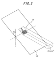
- FIGS. 1 and 2 there is shown an illustration for a vertically polarized wave directional gain decreasing due to the slope of an antenna.
- a front glass 12 on which a planar antenna 10 is formed is vertical
- an essential effective aperture area of the planar antenna for a vertically polarized wave propagating in a horizontal direction is assumed to be S.
- the front glass 12 is sloped, assuming that an angle of slope (an angle of slope from a vertical directional) is ⁇ , the effective aperture area in a horizontal direction becomes S ⁇ cos ⁇ .
- An object of the present invention is to provide a ground wave reception antenna unit which does not cause a decrease in a directional gain during the reception of a vertically polarized wave even when an antenna is positioned inclining from a vertical direction.
- Another object of the present invention is to provide a gain adjustment method for improving a directional gain at the time of a vertical polarized wave reception when an antenna is positioned inclining from a vertical direction.
- the present invention uses a reflector positioned in a horizontal direction or inclining from the horizontal direction by a predetermined angle for an antenna positioned with being inclined so as to increase an effective aperture area of the antenna to a vertically polarized wave propagating in a horizontal direction, thereby improving a directional gain of the antenna. Moreover, a horizontal directional characteristic improved in this way becomes almost non-directional.
- a first aspect of the present invention is a ground wave reception antenna unit comprising a planar antenna for receiving a vertically polarized wave propagating in a horizontal direction, the antenna being positioned inclining from a vertical direction, and a reflector positioned in a horizontal direction or inclining from the horizontal direction by a predetermined angle with being spaced from the planner antenna by a predetermined distance.
- the predetermined angle is 0-30°, more preferably is 6°.
- the reflector is either positioned in close proximity to the planar antenna or is positioned such that a predetermined distance between the planar antenna and the reflector is integer multiples of 0.5 ⁇ , herein ⁇ is a wavelength of a ground wave received by the planar antenna.
- a second aspect of the present invention is a method for regulating a directional gain of a planar antenna in a ground wave reception antenna unit for receiving a vertical polarized wave propagating in a horizontal direction, the planar antenna being positioned inclining from a vertical direction, the method comprising the steps of positioning a reflector in a horizontal direction or with inclining from the horizontal direction by a predetermined angle while spacing the reflector from the planner antenna by a predetermined distance, and selecting the predetermined distance so that the directional gain is improved, comparing to a case where the reflector is not provided.
- the reflector is either positioned in close proximity to the planar antenna or is positioned such that a predetermined distance between the planar antenna and the reflector is integer multiples of 0.5 ⁇ , herein ⁇ is a wave length of the ground wave received by the planar antenna.
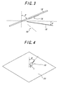
- FIG. 3 shows one embodiment of a ground wave reception antenna unit of the present invention.
- a planar antenna 10 is provided on a glass plate 16 which is sloped by an angle of ⁇ from a vertical direction.
- the glass plate corresponds to a front glass or rear glass.
- This ground wave reception antenna unit comprises a reflector positioned under the planar antenna 10, the reflector extending in a horizontal direction or inclining by an angle of ⁇ (0 - 30°) from a horizontal direction with being spaced from the planar antenna.
- the reflector is positioned inclining from a horizontal direction by 6°.
- a reflected image antenna 20 is formed by the reflector 18 positioned inclining from a horizontal direction, and an effective aperture area for a vertically polarized wave propagating in a horizontal direction apparently increases from S ⁇ cos ⁇ , In this way, a directional gain for a vertically polarized wave in a horizontal direction is improved.
- the reflector positioned described above has no portion to interrupt an emission characteristic in a horizontal direction, it is possible to make a vertically polarized wave directional gain in a horizontal direction thus obtained non-directional.
- the inventors of the present application have made simulation experiments to see how gain improvement effects will be changed by a distance L between the reflector 18 and the planar antenna 10. Note that the distance L is measured in a vertical direction from the lower end of the planar antenna to the reflector 18.
- FIG. 4 shows an arrangement of the planar antenna 10 and a reflector (an infinite plane) 22 for performing a correlation estimate (simulation) between the reflector distance L and a gain improvement effect.
- the angle ⁇ of inclination of the planar antenna 10 is selected to 60°.
- the reflector 22 is positioned inclining from a horizontal direction by 6°.
- FIG. 5 there is shown an estimation result as to how a gain improvement effect is obtained by placing the reflector in comparison with a state where no reflector is available.
- the abscissas shows the reflector distance L represented by a wavelength ⁇ of a received radio wave, and the ordinate shows an average gain variation (dB). From this correlation estimate, it is clear that, when the reflector distance L is 0 or 0.5 ⁇ , the gain improvement effect takes the maximal value. Further, it is clear that, when the reflector distance L is 0, i.e., the reflector is placed directly under the antenna (but the reflector is not in contact with the antenna), the improvement level is about 5 dB, resulting in the maximum effect.
- the reflector it is suitable for the reflector to be positioned directly under the antenna or arranged at a position of 0.5 ⁇ spaced from the antenna.
- FIG. 6 shows a pattern of the planar antenna 30 of a monopole type having a resonance frequency of 1.7 GHz.
- This planar antenna 30 is formed on a square glass plate 32, and comprises a rectangular ground conductor 34 and an elongated radiating element 36. Feeding points 38, 39 are provided and connected to the radiating element and ground conductor, respectively.
- FIG. 7 there is shown a constitution in which such an antenna is positioned inclining by 66° from a vertical direction and a reflector 40 is positioned inclining by 6° from a horizontal direction.
- the radiating element 36 is positioned in proximity of the reflector 40 as shown in FIG. 7 or the ground conductor 34 is positioned in proximity of the reflector 40 depends on the position where the planar antenna is provided on a window glass of a vehicle, for example.
- FIG. 8 there is shown such an example that a planar antenna 44 in which the ground conductor 34 is positioned in proximity to the reflector 40.
- the distance L is a length from the lower end of the ground conductor 34 to the reflector 40.
- the average gain is -7 dB where the reflector is not used, and 1 dB where the reflector is used. It is clear that, by using the reflector, the directional gain of the horizontal direction vertical polarized wave is improved by 8 dB on an average. It is also clear that a favorable characteristic of a non-directionality is obtained.
- the above-described planar antenna is provided on the inner surface of a sloped window glass (for example, a front glass or a rear glass) of a vehicle, and the reflector is positioned under this planar antenna.
- a sloped window glass for example, a front glass or a rear glass
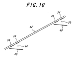
- FIG. 10 shows the positions where the antenna unit of the present embodiment may be provided on the front glass 42 of a vehicle.
- the radiating element 36 is positioned in proximity to the reflector 40
- the ground conductor 34 is positioned in proximity to the reflector 40.
- ground conductor 34 is easily connected to a body portion of a vehicle on the upper inside portion or lower inside portion of the front glass 42, since a body portion of a vehicle works as an earth conductor.
- a reflected image antenna is formed by a reflector positioned in a horizontal direction or inclining from a horizontal direction by a predetermined angle, and, in this way, an antenna effective aperture area for a vertical polarized wave propagating in a horizontal direction can be increased.
- a ground wave reception antenna unit may be implemented in which the directional gain during the reception of a vertically polarized wave does not decrease.
Landscapes
- Aerials With Secondary Devices (AREA)
- Variable-Direction Aerials And Aerial Arrays (AREA)
Applications Claiming Priority (3)
| Application Number | Priority Date | Filing Date | Title |
|---|---|---|---|
| JP2002169467 | 2002-06-11 | ||
| JP2002169467 | 2002-06-11 | ||
| PCT/JP2003/007415 WO2004004069A1 (ja) | 2002-06-11 | 2003-06-11 | 地上波受信用アンテナ装置およびアンテナ利得の調整方法 |
Publications (2)
| Publication Number | Publication Date |
|---|---|
| EP1548880A1 true EP1548880A1 (de) | 2005-06-29 |
| EP1548880A4 EP1548880A4 (de) | 2005-11-09 |
Family
ID=29996448
Family Applications (1)
| Application Number | Title | Priority Date | Filing Date |
|---|---|---|---|
| EP03733363A Withdrawn EP1548880A4 (de) | 2002-06-11 | 2003-06-11 | Empfangsantenneneinrichtung für terrestrische wellen und antennengewinneinstellverfahren |
Country Status (4)
| Country | Link |
|---|---|
| US (1) | US20050174289A1 (de) |
| EP (1) | EP1548880A4 (de) |
| JP (1) | JPWO2004004069A1 (de) |
| WO (1) | WO2004004069A1 (de) |
Cited By (1)
| Publication number | Priority date | Publication date | Assignee | Title |
|---|---|---|---|---|
| CN102394378A (zh) * | 2011-11-01 | 2012-03-28 | 东南大学 | 高增益垂直极化全金属扇区天线 |
Families Citing this family (2)
| Publication number | Priority date | Publication date | Assignee | Title |
|---|---|---|---|---|
| US8011104B2 (en) * | 2006-04-10 | 2011-09-06 | The Gillette Company | Cutting members for shaving razors |
| US8499462B2 (en) * | 2006-04-10 | 2013-08-06 | The Gillette Company | Cutting members for shaving razors |
Family Cites Families (11)
| Publication number | Priority date | Publication date | Assignee | Title |
|---|---|---|---|---|
| JP2538329B2 (ja) * | 1988-02-23 | 1996-09-25 | 三洋電機株式会社 | アンテナ装置 |
| JPH02253702A (ja) * | 1989-03-28 | 1990-10-12 | Japan Radio Co Ltd | マイクロストリップアンテナ |
| GB2235590B (en) * | 1989-08-21 | 1994-05-25 | Radial Antenna Lab Ltd | Planar antenna |
| JP2593899Y2 (ja) * | 1992-02-05 | 1999-04-19 | 日本板硝子株式会社 | 自動車用窓ガラスアンテナ装置 |
| US5568156A (en) * | 1992-10-09 | 1996-10-22 | Asahi Glass Company Ltd. | High frequency wave glass antenna for an automobile |
| JPH07273526A (ja) * | 1994-03-30 | 1995-10-20 | Nippon Sheet Glass Co Ltd | 自動車用窓ガラスアンテナ |
| JP3285299B2 (ja) * | 1995-09-13 | 2002-05-27 | シャープ株式会社 | 小型アンテナおよび光ビーコン、電波ビーコン共用車載フロントエンド |
| US5734350A (en) * | 1996-04-08 | 1998-03-31 | Xertex Technologies, Inc. | Microstrip wide band antenna |
| DE19841187C1 (de) * | 1998-09-09 | 2000-02-10 | Hirschmann Richard Gmbh Co | Mobilfunkantenne |
| EP1351335A1 (de) * | 2000-12-07 | 2003-10-08 | Asahi Glass Company Ltd. | Antennenvorrichtung |
| US6919853B2 (en) * | 2002-03-04 | 2005-07-19 | M/A-Com, Inc. | Multi-band antenna using an electrically short cavity reflector |
-
2003
- 2003-06-11 EP EP03733363A patent/EP1548880A4/de not_active Withdrawn
- 2003-06-11 US US10/516,398 patent/US20050174289A1/en not_active Abandoned
- 2003-06-11 JP JP2004517253A patent/JPWO2004004069A1/ja active Pending
- 2003-06-11 WO PCT/JP2003/007415 patent/WO2004004069A1/ja not_active Ceased
Cited By (2)
| Publication number | Priority date | Publication date | Assignee | Title |
|---|---|---|---|---|
| CN102394378A (zh) * | 2011-11-01 | 2012-03-28 | 东南大学 | 高增益垂直极化全金属扇区天线 |
| CN102394378B (zh) * | 2011-11-01 | 2014-01-22 | 东南大学 | 高增益垂直极化全金属扇区天线 |
Also Published As
| Publication number | Publication date |
|---|---|
| WO2004004069A1 (ja) | 2004-01-08 |
| JPWO2004004069A1 (ja) | 2005-11-04 |
| US20050174289A1 (en) | 2005-08-11 |
| EP1548880A4 (de) | 2005-11-09 |
Similar Documents
| Publication | Publication Date | Title |
|---|---|---|
| Schlub et al. | Switched parasitic antenna on a finite ground plane with conductive sleeve | |
| US8174450B2 (en) | Broadband micropatch antenna system with reduced sensitivity to multipath reception | |
| US20090322642A1 (en) | Resonant cap loaded high gain patch antenna | |
| JPH10294614A (ja) | セルラー・アンテナ | |
| EP1365475B1 (de) | Mehrbandantenne mit elektrisch kurzem Hohlraumreflektor | |
| US7205953B2 (en) | Directional antenna array | |
| US6025803A (en) | Low profile antenna assembly for use in cellular communications | |
| WO2015125426A1 (ja) | 集合アンテナ装置 | |
| KR20020024762A (ko) | 평면안테나장치 | |
| US7268733B2 (en) | High frequency glass antenna for automobiles | |
| KR20170120032A (ko) | 지향성 안테나 모듈 | |
| JP3464639B2 (ja) | 多周波用アンテナ | |
| US12294144B2 (en) | Antenna device for vehicle | |
| US20050174289A1 (en) | Terrestrial wave receiving antenna device and antenna gain adjusting method | |
| EP1494317B1 (de) | An einem Fahrzeug angebrachte Schlitzantenne | |
| US6930645B2 (en) | Automotive on-board antenna | |
| JP3793110B2 (ja) | 導体反射板付きモノポールアンテナ | |
| Padhi et al. | Parametric study of a microstrip Yagi antenna | |
| EP1434303A2 (de) | Bordantenne | |
| US7579991B2 (en) | Portable wireless apparatus | |
| US20250007172A1 (en) | Radiation pattern adaptable by obstacle bias | |
| KR102273252B1 (ko) | 주차 관리를 위한 지능형 검지센서 장착용 안테나 | |
| JP4738967B2 (ja) | 円偏波ループアンテナ | |
| WO2025218241A1 (zh) | 车辆 | |
| JP3359491B2 (ja) | 全方位アンテナ |
Legal Events
| Date | Code | Title | Description |
|---|---|---|---|
| PUAI | Public reference made under article 153(3) epc to a published international application that has entered the european phase |
Free format text: ORIGINAL CODE: 0009012 |
|
| 17P | Request for examination filed |
Effective date: 20041208 |
|
| AK | Designated contracting states |
Kind code of ref document: A1 Designated state(s): AT BE BG CH CY CZ DE DK EE ES FI FR GB GR HU IE IT LI LU MC NL PT RO SE SI SK TR |
|
| A4 | Supplementary search report drawn up and despatched |
Effective date: 20050922 |
|
| STAA | Information on the status of an ep patent application or granted ep patent |
Free format text: STATUS: THE APPLICATION HAS BEEN WITHDRAWN |
|
| 18W | Application withdrawn |
Effective date: 20060523 |