EP1548294A2 - Curtain rod support - Google Patents
Curtain rod support Download PDFInfo
- Publication number
- EP1548294A2 EP1548294A2 EP04030430A EP04030430A EP1548294A2 EP 1548294 A2 EP1548294 A2 EP 1548294A2 EP 04030430 A EP04030430 A EP 04030430A EP 04030430 A EP04030430 A EP 04030430A EP 1548294 A2 EP1548294 A2 EP 1548294A2
- Authority
- EP
- European Patent Office
- Prior art keywords
- support according
- recess
- fixing means
- longitudinal axis
- opening
- Prior art date
- Legal status (The legal status is an assumption and is not a legal conclusion. Google has not performed a legal analysis and makes no representation as to the accuracy of the status listed.)
- Withdrawn
Links
Images





Classifications
-
- A—HUMAN NECESSITIES
- A47—FURNITURE; DOMESTIC ARTICLES OR APPLIANCES; COFFEE MILLS; SPICE MILLS; SUCTION CLEANERS IN GENERAL
- A47H—FURNISHINGS FOR WINDOWS OR DOORS
- A47H1/00—Curtain suspension devices
- A47H1/10—Means for mounting curtain rods or rails
- A47H1/14—Brackets for supporting rods or rails
Definitions
- the present invention relates to a rod support with multiple means of fixation.
- the field of the invention is that of living quarters in which find decorative materials that obscure the windows, such as curtains or curtains, and separating materials fencing shower trays or bathtubs, and opposing splashing water, such as shower curtains.
- These materials are present in the form of flexible panels of fabrics or plastics, arranged mobile way on rods, usually via hooks or rings.
- rods generally of circular or rectangular section, full or hollow, are positioned on a fixed structure, for example a wall or a partition, via rod supports. These are usually located near the ends of those, often at the ends.
- rod supports are commonly in the form of a metal or plastic body.
- This body is connected at one end to a plate perpendicular to the axis of the body and provided with screw holes, allowing its fixation on a support surface.
- This body has at its other end a recess of circular or rectangular section adapted to receive rods, the plane of this recess being perpendicular to the axis of the rod and to the plane of the surface support.
- the rod can be locked in this recess with a screw of blocking. This screw is supported in a screw hole on the periphery of the recess and in the plane of the latter.
- the locking screw is indispensable and complicates the support structure.
- it can damage the surface of a rod by stripe or punching, especially if the latter has a decorative role or if it has a hollow section.
- the invention proposes to overcome these various limitations by means of a advanced rod support.
- it also comprises a second fixing means adapted to a second type of rod different from the first type.
- the first fixing means comprises a first cylindrical recess opening on its end face, this recess presenting a first predetermined section and a first longitudinal axis parallel to its back side.
- the first means further comprises a first slot perpendicular to the first longitudinal axis and opening into the first recess.
- the second means comprises a second recess cylindrical opening on its front face, this recess having a second predetermined section different from the first section and a second axis longitudinal parallel to its rear face.
- the second means further comprises a perpendicular slot at the second longitudinal axis and opening into the second recess.
- the first means is able to receive section rods circular diameter between 6 and 8 millimeters
- the second means is able to receive rods with circular section of diameter between 9 and 12 millimeters.
- the first means comprises a third recess parallelepiped coplanar to its rear face and opening on its front face, this recess having a third predetermined section and a third axis longitudinal.
- the second means further comprises a third slot perpendicular to the third longitudinal axis, this slot crossing the third recess and opening on its front face.
- the second and third recesses are coaxial.
- it also comprises a third means of fixation.
- the third means comprises a fourth recess parallelepiped coplanar to its rear face and opening on its front face, this recess having a fourth predetermined section and a fourth longitudinal axis.
- the third means further comprises a fourth slot perpendicular to the fourth longitudinal axis, this slot crossing the fourth recess and opening on its front face.
- first and fourth recesses are coaxial.
- the support comprises a fourth fixing means.
- the fourth means comprises a fifth coplanar parallelepipedic recess at its rear face and opening onto its front face, this recess having a fifth predetermined section and a fifth longitudinal axis.
- the fourth means further comprises a fifth slot perpendicular to the fifth longitudinal axis, this slot crossing the fifth recess and opening on its front face.
- the support is adapted to a rod having a section rectangular of 12 by 8 millimeters.
- the second and fourth recesses are coaxial.
- the fixing means have axes coplanar with angular offset.
- the angular offset is 90 °.
- the fixing means are arranged in a body cylindrical.
- the cylindrical body is made of an elastic material, so that it allows the fixing of the rods by interlocking.
- the securing means consist of an adhesive.
- the securing means consist of an orifice, so that the support can be screwed on the structure.
- this support has an adjustable hood on the body and presenting openings adapted to the fastening means.
- the hood includes clipping means on the body cylindrical.
- the hood includes locking means for blocking a rod in translation.
- At least one of the support elements is presented under the shape of a pre-cut area.
- At least one of the fastening means present against rods, reliefs intended to immobilize a rod in rotation and in translation.
- Figure 1 shows a rod support.
- the latter consists of a PLA plate and COR body.
- the PLA plate delimited by two parallel planes corresponding to the face FAA back and the PLM middle face is usually discoidal. She can be secured by its FAA back side on a support surface locally coplanar to FAA by gluing or screwing. In the latter case, she is equipped a central screwing hole ORI, or several screw holes.
- the COR body is generally cylindrical, delimited by two sections coplanar lines with two parallel planes FAA, PLM.
- the PLM middle face is common to the COR body and the PLA plate, the COR body being affixed on the PLA plate.
- the two volumes of COR and the PLA plate can be molded unitarily and constitute a plastic part unique. This piece has a certain elasticity suitable for interlocking rods.
- This COR body has a main AX axis common to the PLA plate and to the screw hole ORI. In order to allow the passage of a screw, it presents a cavity longitudinal axis coaxial with this main axis AX.
- the body COR is provided with several means for fixing rods of to be able to receive different types and dimensions of rods.
- the body COR present, according to two diametrically opposed generatrices of the cylinder the constituting a first slot FENi over all or part of its height.
- This slot FENi crosses a first cylindrical recess EVIi of diameter less than or equal to that of the circular section rod can be fixed, this recess is more close to the FAF front face than the PLM center face and the back face.
- the axis AXEi of this cylindrical recess EVIi is secant and perpendicular to the axis main AX.
- the COR body can also present a second slot FENj and a second recess EVIj, this last of diameter different from that of the first recess EVIi, and disposed of way that they do not interfere geometrically with the first slot FENi and the first recess EVIi.
- the slots FENi, FENj, and the recesses EVIi, EVIj may be perpendicular.
- the axis AXEj of this second cylindrical recess EVIj is also secant and perpendicular to the main axis AX. In other words, the three axes AX, AXEi and AXEj constitute a right trihedron.
- one of the recesses EVIi, EVIj is adapted to rods of 6 to 8 millimeters in diameter, the other to rods of 9 to 12 mm diameter. It does not matter whether the latter have solid sections or hollow. This means that the nominal diameters of the respective recesses EVIi, EVIj will be of the order of 6 and 9 mm, so as to be able to work the body in flexion.
- the COR body can also present a third slot FENk and a third recess EVIk cuboid.
- the axis AXEk of this recess EVIk is secant and perpendicular to the main axis AX.
- the large median M1k of the section of this third recess EVIk is perpendicular to the generatrices of the cylinder constituting the body COR. This allows to position a rod with rectangular section so that the large median M1k of the section is vertical, which gives it a better module of bending only when the small median M2k of the section is vertical.
- this EVIk rectangular recess is suitable for rods of 12 mm by 8 mm, figures corresponding to the dimensions of both medians M1k, M2k.
- the third recess EVIk can be indifferently arranged in cooperation with one of the previous recesses, or remain independent of the latter, provided that there is no interference between the different recesses so as to retain sufficient quantities of material to support a positioned rod. In the present embodiment, it preferably cooperates with the second recess EVIj, which assumes less removal of material than in the case of cooperation with the former EVIi recess which has a smaller volume.
- the third axis AXEk is located then confused with the second axis AXEj.
- a fourth means of fixing rods in the form of a slot and a parallelepiped recess, the latter being able to be coaxial with one of the previous cylindrical recesses not cooperating with the third means.
- recesses rectangular can be adapted to the fixing of two families of rectangular section or, more generally, rods whose section presents two parallel faces.
- Figures 6 and 7 show a hood CAP.
- This hood allows the locking a rod fixed on the body COR.
- the CAP cover has a FUT of cylindrical shape and coaxial with the body COR along the main axis AX. It was FUT is delimited by two straight sections coplanar with two parallel planes corresponding to the medial face bis PLM 'and the front face bis FAF'.
- FUT When setting up of this hood CAP, its was FUT bears on the plate PLA and the planes corresponding to the median PLM and median bis PLM 'merge.
- the was FUT is closed by a flat bottom corresponding to the frontal face bis FAF '.
- this cover CAP has slots FENi ', FENj' and recesses EVIi ', EVIj', EVIk ' positioned and dimensioned in a similar manner to their counterparts of the COR body, respectively FENi, FENj and EVIi, EVIj, EVIk.
- slots FENi ', FENj' are thus arranged along generators of the cylinder constituting the cap CAP. Slots FENi ', FENj' meet recesses EVI 1 ', EVI 2', EVI k 'at their opposite ends to those opposite the fixed structure, or close to the plane corresponding to the front face FAF '.
- CAP hood must have slots FENi ', FENj' of equivalent width to the recesses associated EVIi ', EVIj', EVIk ', the cap CAP itself consists of an elastic material being unfit by its geometry to work in deformation.
- the CAP cover can be clipped or screwed onto the COR cylindrical body using adequate devices not shown, vis-à-vis, near the median plane PLM. Depending on its conformation, the CAP cover can be clipped or screwed on the PLA plate, then carrier of the aforementioned devices.
- Screws FENi, FENi ', FENj, FENj', FENk and recesses EVIi, EVIi ', EVIj, EVIj 'of the body COR and CAP CAP and the axial orifice ORI passage a screw may be in the form of thin solid areas pre-cut and can be removed depending on the fixation to achieve.
- the body COR may furthermore present at its recesses EVIi, EVIj, EVIk and with regard to the rods concave to convex reliefs, recessed or in bump, not shown, allowing immobilization in rotation of these rods, and can cooperate with complementary reliefs arranged on the rods.
Landscapes
- Mutual Connection Of Rods And Tubes (AREA)
- Load-Bearing And Curtain Walls (AREA)
Abstract
Description
La présente invention concerne un support de tringle à multiples moyens de fixation.The present invention relates to a rod support with multiple means of fixation.
Le domaine de l'invention est celui des locaux d'habitation dans lesquels se trouvent des matériaux décoratifs occultant les fenêtres, tels des voilages ou des rideaux, et des matériaux séparatifs clôturant des bacs à douche ou des baignoires, et s'opposant aux projections d'eau, tels des rideaux de douche. Ces matériaux se présentent sous la forme de panneaux souples de tissus ou plastiques, agencés de façon mobile sur des tringles, généralement par l'intermédiaire de crochets ou d'anneaux. Ces tringles, généralement de section circulaire ou rectangulaire, pleines ou creuses, sont positionnées sur une structure fixe, par exemple un mur ou une cloison, par l'intermédiaire de supports de tringles. Ceux-ci sont généralement situés à proximité des extrémités de celles-là, souvent aux extrémités.The field of the invention is that of living quarters in which find decorative materials that obscure the windows, such as curtains or curtains, and separating materials fencing shower trays or bathtubs, and opposing splashing water, such as shower curtains. These materials are present in the form of flexible panels of fabrics or plastics, arranged mobile way on rods, usually via hooks or rings. These rods, generally of circular or rectangular section, full or hollow, are positioned on a fixed structure, for example a wall or a partition, via rod supports. These are usually located near the ends of those, often at the ends.
Ces supports de tringle se présentent communément sous la forme d'un corps métallique ou plastique. Ce corps est relié par une extrémité à une plaque perpendiculaire à l'axe du corps et munie de trous de vissage, permettant sa fixation sur une surface support. Ce corps présente à son autre extrémité un évidement de section circulaire ou rectangulaire apte à recevoir des tringles, le plan de cet évidement étant perpendiculaire à l'axe de la tringle et au plan de la surface support. La tringle peut être bloquée dans cet évidement à l'aide d'une vis de blocage. Cette vis prend appui dans un trou de vis ménagé à la périphérie de l'évidement et dans le plan de ce dernier.These rod supports are commonly in the form of a metal or plastic body. This body is connected at one end to a plate perpendicular to the axis of the body and provided with screw holes, allowing its fixation on a support surface. This body has at its other end a recess of circular or rectangular section adapted to receive rods, the plane of this recess being perpendicular to the axis of the rod and to the plane of the surface support. The rod can be locked in this recess with a screw of blocking. This screw is supported in a screw hole on the periphery of the recess and in the plane of the latter.
De tels supports présentent plusieurs limitations.Such carriers have several limitations.
Premièrement, ils admettent exclusivement une gamme de tringles de section circulaire ou rectangulaire, limitée strictement en section par celle de l'évidement.First, they admit exclusively a range of rods of circular or rectangular section, strictly limited in section by that of the recess.
Deuxièmement, ils nécessitent l'introduction de la tringle par enfilement en biais tout d'abord dans un premier support, puis par translation ensuite dans un deuxième support. Cela nécessite de pouvoir disposer d'un certain espace de manoeuvre d'une part entre la tringle et des cloisons éventuelles perpendiculaires à la surface support et d'autre part entre la tringle et la surface support. Cela nécessite également un certain jeu à l'intérieur des évidements rendant impossible la fixation d'une tringle de diamètre proche ou égal au diamètre nominal de l'évidement. L'espace entre la tringle et la surface support augmente le porte à faux et fragilise donc la fixation du support sur la surface de support. Second, they require the introduction of the rod by threading into bias first in a first support, then by translation then in a second support. This requires having a certain space of on the one hand between the rod and any partitions perpendicular to the support surface and secondly between the rod and the support surface. it also requires some play inside the recesses making it impossible fixing a rod of diameter close to or equal to the nominal diameter of the recess. The space between the rod and the support surface increases the cantilever and therefore weakens the attachment of the support on the support surface.
Troisièmement, la vis de blocage est indispensable et complique la structure du support. De plus, elle peut endommager la surface d'une tringle par rayure ou poinçonnement, d'autant plus si cette dernière a un rôle décoratif ou si elle présente une section creuse.Thirdly, the locking screw is indispensable and complicates the support structure. In addition, it can damage the surface of a rod by stripe or punching, especially if the latter has a decorative role or if it has a hollow section.
L'invention se propose de pallier ces différentes limitations au moyen d'un support de tringle perfectionné.The invention proposes to overcome these various limitations by means of a advanced rod support.
Selon l'invention, un support de tringle comprend :
- des moyens d'assujettissement de sa face arrière sur une structure fixe,
- un premier moyen de fixation adapté à un premier type de tringle,
- means for securing its rear face on a fixed structure,
- a first fastening means adapted to a first type of rod,
De plus, il comporte également un deuxième moyen de fixation adapté à un second type de tringle différent du premier type.In addition, it also comprises a second fixing means adapted to a second type of rod different from the first type.
Avantageusement, le premier moyen de fixation comporte un premier évidement cylindrique débouchant sur sa face frontale, cet évidement présentant une première section prédéterminée et un premier axe longitudinal parallèle à sa face arrière.Advantageously, the first fixing means comprises a first cylindrical recess opening on its end face, this recess presenting a first predetermined section and a first longitudinal axis parallel to its back side.
Dans ce cas, le premier moyen comporte de plus une première fente perpendiculaire au premier axe longitudinal et débouchant dans le premier évidement.In this case, the first means further comprises a first slot perpendicular to the first longitudinal axis and opening into the first recess.
Avantageusement, le second moyen comporte un second évidement cylindrique débouchant sur sa face frontale, cet évidement présentant une deuxième section prédéterminée différente de la première section et un second axe longitudinal parallèle à sa face arrière.Advantageously, the second means comprises a second recess cylindrical opening on its front face, this recess having a second predetermined section different from the first section and a second axis longitudinal parallel to its rear face.
Dans ce cas, le second moyen comporte de plus une fente perpendiculaire au second axe longitudinal et débouchant dans le second évidement.In this case, the second means further comprises a perpendicular slot at the second longitudinal axis and opening into the second recess.
Dans ce cas, le premier moyen est apte à recevoir des tringles à section circulaire de diamètre compris entre 6 et 8 millimètres, et le deuxième moyen est apte à recevoir des tringles à section circulaire de diamètre compris entre 9 et 12 millimètres.In this case, the first means is able to receive section rods circular diameter between 6 and 8 millimeters, and the second means is able to receive rods with circular section of diameter between 9 and 12 millimeters.
Particulièrement, le premier moyen comporte un troisième évidement parallélépipédique coplanaire à sa face arrière et débouchant sur sa face frontale, cet évidement présentant une troisième section prédéterminée et un troisième axe longitudinal.In particular, the first means comprises a third recess parallelepiped coplanar to its rear face and opening on its front face, this recess having a third predetermined section and a third axis longitudinal.
Dans ce cas, le deuxième moyen comporte de plus une troisième fente perpendiculaire au troisième axe longitudinal, cette fente traversant le troisième évidement et débouchant sur sa face frontale.In this case, the second means further comprises a third slot perpendicular to the third longitudinal axis, this slot crossing the third recess and opening on its front face.
Dans ce cas, les deuxième et troisième évidements sont coaxiaux. In this case, the second and third recesses are coaxial.
Selon une autre variante, il comporte également un troisième moyen de fixation.According to another variant, it also comprises a third means of fixation.
Dans ce cas, le troisième moyen comporte un quatrième évidement parallélépipédique coplanaire à sa face arrière et débouchant sur sa face frontale, cet évidement présentant une quatrième section prédéterminée et un quatrième axe longitudinal.In this case, the third means comprises a fourth recess parallelepiped coplanar to its rear face and opening on its front face, this recess having a fourth predetermined section and a fourth longitudinal axis.
Dans ce cas, le troisième moyen comporte de plus une quatrième fente perpendiculaire au quatrième axe longitudinal, cette fente traversant le quatrième évidement et débouchant sur sa face frontale.In this case, the third means further comprises a fourth slot perpendicular to the fourth longitudinal axis, this slot crossing the fourth recess and opening on its front face.
Particulièrement, les premier et quatrième évidements sont coaxiaux.In particular, the first and fourth recesses are coaxial.
Particulièrement, le support comporte un quatrième moyen de fixation.In particular, the support comprises a fourth fixing means.
Selon une autre variante, le quatrième moyen comporte un cinquième évidement parallélépipédique coplanaire à sa face arrière et débouchant sur sa face frontale, cet évidement présentant une cinquième section prédéterminée et un cinquième axe longitudinal.According to another variant, the fourth means comprises a fifth coplanar parallelepipedic recess at its rear face and opening onto its front face, this recess having a fifth predetermined section and a fifth longitudinal axis.
Dans ce cas, le quatrième moyen comporte de plus une cinquième fente perpendiculaire au cinquième axe longitudinal, cette fente traversant le cinquième évidement et débouchant sur sa face frontale.In this case, the fourth means further comprises a fifth slot perpendicular to the fifth longitudinal axis, this slot crossing the fifth recess and opening on its front face.
Particulièrement, le support est adapté à une tringle présentant une section rectangulaire de 12 par 8 millimètres.In particular, the support is adapted to a rod having a section rectangular of 12 by 8 millimeters.
Avantageusement, les deuxième et quatrième évidements sont coaxiaux.Advantageously, the second and fourth recesses are coaxial.
Particulièrement, certains au moins des moyens de fixation ont des axes coplanaires présentant un décalage angulaire.In particular, at least some of the fixing means have axes coplanar with angular offset.
Précisément, le décalage angulaire est de 90°.Precisely, the angular offset is 90 °.
Généralement, les moyens de fixation sont agencés dans un corps cylindrique.Generally, the fixing means are arranged in a body cylindrical.
Précisément, le corps cylindrique est constitué d'un matériau élastique, de sorte qu'il permette la fixation des tringles par emboítement.Specifically, the cylindrical body is made of an elastic material, so that it allows the fixing of the rods by interlocking.
En outre, les moyens d'assujettissement consistent en un adhésif.In addition, the securing means consist of an adhesive.
En outre, les moyens d'assujettissement consistent en un orifice, de sorte que le support puisse être vissé sur la structure.In addition, the securing means consist of an orifice, so that the support can be screwed on the structure.
De plus, ce support comporte un capot ajustable sur le corps et présentant des ouvertures adaptées aux moyens de fixation.In addition, this support has an adjustable hood on the body and presenting openings adapted to the fastening means.
Par exemple, le capot comprend des moyens de clipsage sur le corps cylindrique. For example, the hood includes clipping means on the body cylindrical.
En outre, le capot comprend des moyens de verrouillage pour bloquer une tringle en translation.In addition, the hood includes locking means for blocking a rod in translation.
Particulièrement, l'un au moins des éléments du support se présente sous la forme d'une zone prédécoupée.In particular, at least one of the support elements is presented under the shape of a pre-cut area.
Eventuellement, l'un au moins des moyens de fixation présente en regard des tringles, des reliefs prévus pour immobiliser une tringle en rotation et en translation.Optionally, at least one of the fastening means present against rods, reliefs intended to immobilize a rod in rotation and in translation.
La présente invention apparaítra maintenant avec plus de détails dans le cadre de la description qui suit d'exemples de réalisation donnés à titre illustratif en se référant aux figures jointes, parmi lesquelles :
- la figure 1 représente un support de tringle, constitué d'un corps et d'une plaque,
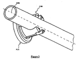
- la figure 2 représente une tringle circulaire de petit diamètre fixée sur le support,
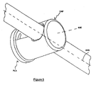
- la figure 3 représente une tringle circulaire de grand diamètre fixée sur le support,
- la figure 4 représente une tringle rectangulaire fixée sur le support,
- la figure 5 représente un capot ajusté sur une tringle circulaire de petit diamètre fixée sur le support,
- la figure 6 représente un capot présentant les passages destinés à des tringles circulaires de petit diamètre, et
- la figure 7 représente un capot présentant les passages destinés à des tringles circulaires de grand diamètre, ainsi qu'à des tringles rectangulaires.
- FIG. 1 represents a rod support consisting of a body and a plate,
- FIG. 2 represents a circular rod of small diameter fixed on the support,
- FIG. 3 represents a circular rod of large diameter fixed on the support,
- FIG. 4 represents a rectangular rod fixed on the support,
- FIG. 5 represents a hood fitted on a small diameter circular rod fixed on the support,
- FIG. 6 represents a cover presenting the passages intended for circular rods of small diameter, and
- Figure 7 shows a cover having the passages for circular rods of large diameter, as well as rectangular rods.
Les éléments présents dans plusieurs figures sont affectés d'une seule et même référence.The elements present in several figures are assigned a single and same reference.
La figure 1 présente un support de tringle. Ce dernier se compose d'une plaque PLA et d'un corps COR.Figure 1 shows a rod support. The latter consists of a PLA plate and COR body.
La plaque PLA délimitée par deux plans parallèles correspondant à la face arrière FAA et à la face médiane PLM est généralement de forme discoïdale. Elle peut s'assujettir par sa face arrière FAA sur une surface support localement coplanaire à FAA par collage ou par vissage. Dans de dernier cas, elle est munie d'un orifice central de vissage ORI, ou de plusieurs orifices de vissage.The PLA plate delimited by two parallel planes corresponding to the face FAA back and the PLM middle face is usually discoidal. She can be secured by its FAA back side on a support surface locally coplanar to FAA by gluing or screwing. In the latter case, she is equipped a central screwing hole ORI, or several screw holes.
Le corps COR est généralement cylindrique, délimité par deux sections droites coplanaires à deux plans parallèles FAA, PLM. La face médiane PLM est commune au corps COR et à la plaquette PLA, le corps COR se trouvant apposé sur la plaque PLA. Concrètement, les deux volumes que constituent le corps COR et la plaque PLA peuvent être moulés unitairement et constituer une pièce plastique unique. Cette pièce présente une certaine élasticité apte à l'emboítement des tringles.The COR body is generally cylindrical, delimited by two sections coplanar lines with two parallel planes FAA, PLM. The PLM middle face is common to the COR body and the PLA plate, the COR body being affixed on the PLA plate. In concrete terms, the two volumes of COR and the PLA plate can be molded unitarily and constitute a plastic part unique. This piece has a certain elasticity suitable for interlocking rods.
Ce corps COR présente un axe principal AXE commun à la plaque PLA et à l'orifice de vissage ORI. Afin d'autoriser le passage d'une vis, il présente une cavité longitudinale coaxiale à cet axe principal AXE.This COR body has a main AX axis common to the PLA plate and to the screw hole ORI. In order to allow the passage of a screw, it presents a cavity longitudinal axis coaxial with this main axis AX.
Le corps COR est muni de plusieurs moyens de fixation de tringles de façon à pouvoir recevoir différents types et dimensions de tringles.The body COR is provided with several means for fixing rods of to be able to receive different types and dimensions of rods.
Tout d'abord, relativement à un premier moyen de fixation, le corps COR présente, selon deux génératrices diamétralement opposées du cylindre le constituant, une première fente FENi sur tout ou partie de sa hauteur. Cette fente FENi croise un premier évidement EVIi cylindrique de diamètre inférieur ou égal à celui de la tringle à section circulaire pouvant y être fixée, cet évidement est plus proche de la face frontale FAF que de la face médiane PLM et de la face arrière. L'axe AXEi de cet évidement cylindrique EVIi est sécant et perpendiculaire à l'axe principal AXE.First, relative to a first attachment means, the body COR present, according to two diametrically opposed generatrices of the cylinder the constituting a first slot FENi over all or part of its height. This slot FENi crosses a first cylindrical recess EVIi of diameter less than or equal to that of the circular section rod can be fixed, this recess is more close to the FAF front face than the PLM center face and the back face. The axis AXEi of this cylindrical recess EVIi is secant and perpendicular to the axis main AX.
Lors de la fixation d'une tringle circulaire dans l'évidement EVIi, ainsi que représenté sur la figure 2, il est nécessaire d'assujettir le support sur la surface d'appui de telle façon que l'axe de l'évidement EVIi soit horizontal comme celui de la plupart des tringles une fois positionnées. Ensuite, la fixation est réalisée par emboítement, en appuyant légèrement sur la tringle présentée à l'extrémité de la fente FENi. Les deux parties du corps COR délimitées par la fente FENi vont alors subir une flexion du fait de l'élasticité du matériau constituant le corps COR, les déformations étant minimisées du fait de la présence de cette fente FENi sur tout ou partie de la hauteur du corps COR. La flexion maximale se produit lorsque la tringle est introduite dans la partie de la fente FENi externe à l'évidement EVIi. Elle diminue lorsque la tringle arrive en position dans l'évidement EVIi. Si le diamètre de la tringle est légèrement supérieur à celui de l'évidement EVIi, il demeure une flexion résiduelle compatible avec l'élasticité du matériau. Il faut préciser que ce dernier doit travailler en déformation élastique et non plastique, sinon il subirait des déformations permanentes voire des ruptures.When attaching a circular rod in the EVIi recess, as well as shown in Figure 2, it is necessary to secure the support on the surface in such a way that the axis of the recess EVIi is horizontal like that of most of the rods once positioned. Then the fixation is carried out by nesting, by lightly pressing on the rod presented at the end of the FENi slot. The two parts of the COR body delimited by the slot FENi will then bending due to the elasticity of the material constituting the COR body, deformations being minimized because of the presence of this slot FENi on any or part of the height of the body COR. Maximum bending occurs when the rod is introduced into the part of the slot FENi external to the EVIi recess. She decreases when the rod arrives in position in the recess EVIi. If the diameter of the rod is slightly greater than that of the recess EVIi, it remains a residual bending compatible with the elasticity of the material. It should be noted that this the last must work in elastic and non-plastic deformation, otherwise he would suffer permanent deformations or even breaks.
Ensuite, relativement à un deuxième moyen de fixation, le corps COR peut présenter également une deuxième fente FENj et un deuxième évidement EVIj, ce dernier de diamètre différent de celui du premier évidement EVIi, et disposé de telle façon qu'ils n'interfèrent géométriquement pas avec la première fente FENi et le premier évidement EVIi. Pour des raisons de facilité de réalisation et de tenue mécanique, les fentes FENi, FENj, et les évidements EVIi, EVIj peuvent être perpendiculaires. L'axe AXEj de ce deuxième évidement cylindrique EVIj est également sécant et perpendiculaire à l'axe principal AXE. Autrement dit, les trois axes AXE, AXEi et AXEj constituent un trièdre droit.Then, relative to a second fixing means, the COR body can also present a second slot FENj and a second recess EVIj, this last of diameter different from that of the first recess EVIi, and disposed of way that they do not interfere geometrically with the first slot FENi and the first recess EVIi. For reasons of ease of realization and of holding mechanically, the slots FENi, FENj, and the recesses EVIi, EVIj may be perpendicular. The axis AXEj of this second cylindrical recess EVIj is also secant and perpendicular to the main axis AX. In other words, the three axes AX, AXEi and AXEj constitute a right trihedron.
La fixation d'une tringle circulaire dans le deuxième évidement EVIj se déroule de façon analogue au positionnement d'une tringle circulaire dans le premier évidement EVIi. Elle se trouve représentée figure 3.Fixing a circular rod in the second recess EVIj is unfolds in a similar way to the positioning of a circular rod in the first recess EVIi. It is represented in figure 3.
Afin de correspondre aux calibres de tringles à section circulaire communément commercialisées, l'un des évidements EVIi, EVIj est adapté à des tringles de 6 à 8 millimètres de diamètre, l'autre à des tringles de 9 à 12 mm de diamètre. Peu importe que ces dernières présentent des sections pleines ou creuses. Cela signifie que les diamètres nominaux des évidements respectifs EVIi,EVIj seront de l'ordre de 6 et 9 mm, de façon à pouvoir faire travailler le corps en flexion.To match the sizes of circular section rods commonly marketed, one of the recesses EVIi, EVIj is adapted to rods of 6 to 8 millimeters in diameter, the other to rods of 9 to 12 mm diameter. It does not matter whether the latter have solid sections or hollow. This means that the nominal diameters of the respective recesses EVIi, EVIj will be of the order of 6 and 9 mm, so as to be able to work the body in flexion.
Ensuite, relativement à un troisième moyen de fixation, le corps COR peut également présenter une troisième fente FENk et un troisième évidement EVIk parallélépipédique. L'axe AXEk de cet évidement EVIk est sécant et perpendiculaire à l'axe principal AXE.Then, relative to a third attachment means, the COR body can also present a third slot FENk and a third recess EVIk cuboid. The axis AXEk of this recess EVIk is secant and perpendicular to the main axis AX.
La grande médiane M1k de la section de ce troisième évidement EVIk est perpendiculaire aux génératrices du cylindre constituant le corps COR. Ceci permet de positionner une tringle à section rectangulaire de telle façon que la grande médiane M1k de la section soit verticale, ce qui lui donne un meilleur module de flexion que lorsque la petite médiane M2k de la section est verticale.The large median M1k of the section of this third recess EVIk is perpendicular to the generatrices of the cylinder constituting the body COR. this allows to position a rod with rectangular section so that the large median M1k of the section is vertical, which gives it a better module of bending only when the small median M2k of the section is vertical.
La fixation d'une telle tringle se fait de façon analogue à celui des tringles circulaires préalablement présentées, et se trouve représenté figure 4.The fixing of such a rod is done in a similar way to that of the rods previously presented circular, and is shown in Figure 4.
Afin de correspondre à un calibre de tringle à section rectangulaire largement commercialisé, cet évidement rectangulaire EVIk est adapté à des tringles de 12 mm par 8 mm, chiffres correspondant aux dimensions des deux médianes M1k, M2k.In order to match a rod gauge with rectangular section widely marketed, this EVIk rectangular recess is suitable for rods of 12 mm by 8 mm, figures corresponding to the dimensions of both medians M1k, M2k.
Le troisième évidement EVIk peut être indifféremment agencé en coopération avec l'un des évidements précédents, ou bien demeurer indépendant de ces derniers, à la condition impérative qu'il n'y ait aucune interférence entre les différents évidements de façon à conserver des quantités suffisantes de matière pour supporter une tringle positionnée. Dans le présent exemple de réalisation, il coopère de préférence avec le deuxième évidement EVIj, ce qui suppose moins d'enlèvement de matière que dans le cas d'une coopération avec le premier évidement EVIi qui présente un moindre volume. Le troisième axe AXEk se trouve alors confondu avec le second axe AXEj.The third recess EVIk can be indifferently arranged in cooperation with one of the previous recesses, or remain independent of the latter, provided that there is no interference between the different recesses so as to retain sufficient quantities of material to support a positioned rod. In the present embodiment, it preferably cooperates with the second recess EVIj, which assumes less removal of material than in the case of cooperation with the former EVIi recess which has a smaller volume. The third axis AXEk is located then confused with the second axis AXEj.
De façon analogue, non représentée sur les figures, il est possible de prévoir un quatrièmes moyen de fixation de tringles sous forme d'une fente et d'un évidement parallélépipédique, ce dernier pouvant être coaxial avec un des évidements cylindriques précédents ne coopérant pas avec le troisième moyen.Similarly, not shown in the figures, it is possible to provide a fourth means of fixing rods in the form of a slot and a parallelepiped recess, the latter being able to be coaxial with one of the previous cylindrical recesses not cooperating with the third means.
Selon un autre type de réalisation, il est possible de prévoir d'autres moyens de fixation. Parmi les évidements correspondants, des évidements rectangulaires peuvent être adaptés à la fixation de deux familles de tringle à section rectangulaire ou, plus généralement, à des tringles dont la section présente deux faces parallèles.According to another type of embodiment, it is possible to provide other fastening means. Of the corresponding recesses, recesses rectangular can be adapted to the fixing of two families of rectangular section or, more generally, rods whose section presents two parallel faces.
En extrapolant à partir de l'exemple de réalisation présenté, il est possible, compte tenu des dimensions respectives du corps et des évidements réalisés, de munir le support d'un nombre quelconque de moyens de fixation pour des tringles de toutes dimensions, ces moyens étant individualisés ou superposés compte tenu des limitations géométriques interdisant de superposer des évidements analogues présentant des tailles différentes. Il est en particulier impossible de prévoir deux évidements cylindriques coaxiaux.By extrapolating from the embodiment shown, it is possible, given the respective dimensions of the body and the recesses made, provide the support with any number of fastening means for rods of any size, these means being individualized or superimposed taking into account geometric limitations prohibiting overlapping similar recesses having different sizes. In particular, it is impossible to foresee two coaxial cylindrical recesses.
Les figures 6 et 7 représentent un capot CAP. Ce capot permet le verrouillage d'une tringle fixée sur le corps COR. Le capot CAP présente un fut FUT de forme cylindrique et coaxial au corps COR suivant l'axe principal AXE. Ce fut FUT est délimité par deux sections droites coplanaires à deux plans parallèles correspondant à la face médiane bis PLM' et à la face frontale bis FAF'. Lors de la mise en place de ce capot CAP, son fut FUT vient en appui sur la plaque PLA et les plans correspondant aux faces médianes PLM et médiane bis PLM' se confondent. Le fut FUT est obturé par un fond plat correspondant à la face frontale bis FAF'. Lors de la mise en place du capot CAP, son fond ne doit pas venir en appui sur l'extrémité du corps COR, si bien qu'on prévoit un intervalle libre de façon à permettre l'hébergement de tringles qui viendraient à dépasser la face frontale FAF sans qu'elles viennent en contact avec la face frontale bis FAF'. De même, le diamètre interne du fut FUT doit excéder le diamètre externe du corps COR, celui ci se trouvant dilaté à son extrémité externe lors de la fixation d'une tringle.Figures 6 and 7 show a hood CAP. This hood allows the locking a rod fixed on the body COR. The CAP cover has a FUT of cylindrical shape and coaxial with the body COR along the main axis AX. It was FUT is delimited by two straight sections coplanar with two parallel planes corresponding to the medial face bis PLM 'and the front face bis FAF'. When setting up of this hood CAP, its was FUT bears on the plate PLA and the planes corresponding to the median PLM and median bis PLM 'merge. The was FUT is closed by a flat bottom corresponding to the frontal face bis FAF '. When placing the CAP cover, its bottom must not bear on the end of the COR body, so that a free interval is provided so that allow accommodation of rods that would exceed the front face FAF without them coming into contact with the frontal face bis FAF '. Similarly, inner diameter of the FUT should exceed the outer diameter of the COR body, this one being dilated at its outer end when fixing a rod.
Afin de permettre l'ajustement du capot CAP sur le corps COR, ce capot CAP présente des fentes FENi', FENj' et des évidements EVIi', EVIj', EVIk' positionnés et dimensionnés de façon analogue à leurs homologues du corps COR, respectivement FENi, FENj et EVIi, EVIj, EVIk. In order to allow the CAP cover to be adjusted on the COR body, this cover CAP has slots FENi ', FENj' and recesses EVIi ', EVIj', EVIk ' positioned and dimensioned in a similar manner to their counterparts of the COR body, respectively FENi, FENj and EVIi, EVIj, EVIk.
Plusieurs fentes FENi', FENj' sont ainsi disposées le long de génératrices du cylindre constituant le fut du capot CAP. Les fentes FENi', FENj' rencontrent des évidements EVIi', EVIj', EVIk' à leurs extrémités opposées à celles en regard de la structure fixe, soit à proximité du plan correspondant à la face frontale FAF'.Several slots FENi ', FENj' are thus arranged along generators of the cylinder constituting the cap CAP. Slots FENi ', FENj' meet recesses EVI 1 ', EVI 2', EVI k 'at their opposite ends to those opposite the fixed structure, or close to the plane corresponding to the front face FAF '.
Afin de permettre sa fixation sur les tringles par emboítement, le capot CAP doit présenter des fentes FENi',FENj' de largeur équivalente aux évidements associés EVIi',EVIj',EVIk', le capot CAP même constitué par un matériau élastique étant inapte de par sa géométrie à travailler en déformation.To allow its attachment to the rods by interlocking, CAP hood must have slots FENi ', FENj' of equivalent width to the recesses associated EVIi ', EVIj', EVIk ', the cap CAP itself consists of an elastic material being unfit by its geometry to work in deformation.
Dans le cas où une tringle est ajustée dans un évidement EVIi de dimensions légèrement inférieures, les parties du corps COR situées de part et d'autre de cet évidement EVIi conservent une flexion élastique résiduelle et le corps COR cylindrique se trouve déformé, ceci d'autant plus que l'on s'éloigne de la plaque PLA. Il convient donc de prévoir un jeu entre le diamètre externe du corps COR et le diamètre interne du fut du capot CAP.In the case where a rod is fitted into a recess EVIi of slightly smaller dimensions, COR body parts located on both sides else of this recess EVIi retain residual elastic flexion and the body COR cylindrical is deformed, this all the more as we move away from the PLA plate. It is therefore necessary to provide a clearance between the outer diameter of the body COR and the inner diameter of the hood CAP.
Le capot CAP peut être clipsé ou vissé sur le corps cylindrique COR à l'aide de dispositifs adéquats non représentés, en vis-à-vis, à proximité du plan médian PLM. En fonction de sa conformation, le capot CAP peut être clipsé ou vissé sur la plaque PLA, alors porteuse des dispositifs précités.The CAP cover can be clipped or screwed onto the COR cylindrical body using adequate devices not shown, vis-à-vis, near the median plane PLM. Depending on its conformation, the CAP cover can be clipped or screwed on the PLA plate, then carrier of the aforementioned devices.
Les fentes FENi, FENi', FENj, FENj', FENk et les évidements EVIi, EVIi', EVIj, EVIj' du corps COR et du capot CAP ainsi que l'orifice axial ORI de passage d'une vis peuvent se présenter sous forme de zones pleines de faible épaisseur prédécoupées et pouvant être ôtées en fonction de la fixation à réaliser.Slots FENi, FENi ', FENj, FENj', FENk and recesses EVIi, EVIi ', EVIj, EVIj 'of the body COR and CAP CAP and the axial orifice ORI passage a screw may be in the form of thin solid areas pre-cut and can be removed depending on the fixation to achieve.
Le corps COR peut en outre présenter au niveau de ses évidements EVIi, EVIj, EVIk et au regard des tringles des reliefs concaves au convexes, en creux ou en bosse, non représentés, permettant l'immobilisation en rotation de ces tringles, et pouvant coopérer avec des reliefs complémentaires agencés sur les tringles.The body COR may furthermore present at its recesses EVIi, EVIj, EVIk and with regard to the rods concave to convex reliefs, recessed or in bump, not shown, allowing immobilization in rotation of these rods, and can cooperate with complementary reliefs arranged on the rods.
Les exemples de réalisation de l'invention présentés ci-dessus ont été choisis eu égard à leur caractère concret. Il ne serait cependant pas possible de répertorier d'une manière exhaustive tous les modes de réalisation que recouvre cette invention. En particulier, tout moyen décrit peut être remplacé par un moyen équivalent sans sortir du cadre de la présente invention. Comme précisé antérieurement, un nombre important de combinaisons de moyens de fixation peut être réalisé dans le cadre de cette invention.The embodiments of the invention presented above have been chosen in view of their concrete nature. It would not be possible, however, to list exhaustively all the embodiments covered by this invention. In particular, any means described may be replaced by means equivalent without departing from the scope of the present invention. As precised previously, a large number of combinations of fastening means can be realized within the scope of this invention.
Claims (29)
Applications Claiming Priority (2)
| Application Number | Priority Date | Filing Date | Title |
|---|---|---|---|
| FR0315238A FR2864179B1 (en) | 2003-12-23 | 2003-12-23 | ROD SUPPORT WITH MULTIPLE FASTENING MEANS |
| FR0315238 | 2003-12-23 |
Publications (2)
| Publication Number | Publication Date |
|---|---|
| EP1548294A2 true EP1548294A2 (en) | 2005-06-29 |
| EP1548294A3 EP1548294A3 (en) | 2006-06-07 |
Family
ID=34531330
Family Applications (1)
| Application Number | Title | Priority Date | Filing Date |
|---|---|---|---|
| EP04030430A Withdrawn EP1548294A3 (en) | 2003-12-23 | 2004-12-22 | Curtain rod support |
Country Status (2)
| Country | Link |
|---|---|
| EP (1) | EP1548294A3 (en) |
| FR (1) | FR2864179B1 (en) |
Family Cites Families (4)
| Publication number | Priority date | Publication date | Assignee | Title |
|---|---|---|---|---|
| FR603790A (en) * | 1924-12-22 | 1926-04-22 | Process for recovering the neutral fat in neutralization pastes | |
| DE3211216C2 (en) * | 1982-03-26 | 1985-07-11 | Karl Heinz 5353 Mechernich Sander | Device for attaching a bracket with a curtain rod to a wall |
| DE29511027U1 (en) * | 1995-07-07 | 1995-09-14 | Fritsch, Eberhard Peter, 60486 Frankfurt | Device for hanging a curtain, a curtain or the like. |
| GB2391456B (en) * | 2002-08-09 | 2004-10-06 | Piing Heh Entpr Co Ltd | Fixing structure for blind brackets and blind rod |
-
2003
- 2003-12-23 FR FR0315238A patent/FR2864179B1/en not_active Expired - Fee Related
-
2004
- 2004-12-22 EP EP04030430A patent/EP1548294A3/en not_active Withdrawn
Also Published As
| Publication number | Publication date |
|---|---|
| EP1548294A3 (en) | 2006-06-07 |
| FR2864179B1 (en) | 2006-03-17 |
| FR2864179A1 (en) | 2005-06-24 |
Similar Documents
| Publication | Publication Date | Title |
|---|---|---|
| EP1644219B1 (en) | Headlight block for motor vehicle and corresponding vehicle | |
| FR2757318A1 (en) | ELECTRICAL CONNECTOR WITH MOUNTING ON A PANEL | |
| WO2000017034A1 (en) | Hollow elongated support structure comprising a transverse flange at each of its ends | |
| FR2929815A1 (en) | SHELF, ESPECIALLY FOR REFRIGERATED FACILITIES. | |
| EP1713662B1 (en) | Bumper face-bar for motor vehicle | |
| EP2097960B1 (en) | Electric equipment carrier | |
| FR3073722A1 (en) | SHELF OF STORAGE / DECORATION | |
| EP1548294A2 (en) | Curtain rod support | |
| FR2910732A1 (en) | Electric equipment e.g. switch, carrier for use in e.g. recess box, has wall extended in overhang from edge in mounting plane for closing part of hole and retractable under mounting plane | |
| FR2888296A1 (en) | CAGE ARRANGEMENT FOR A CAGE NUT. | |
| EP3115623B1 (en) | Device for assembling and locking | |
| WO2005038510A1 (en) | Nose pad device for spectacle frame | |
| EP1876681B1 (en) | Housing with rails for mounting an electrical device | |
| FR2649253A1 (en) | Two-part mounting box, especially for an electrical apparatus | |
| FR2766535A1 (en) | VIBRATION DAMPING SUPPORT AND METHOD FOR MOLDING IT | |
| EP1026356B1 (en) | Glazing panel with means for assembly to an adjoining structure | |
| FR3153102A1 (en) | Device for fixing a fence to a fence post | |
| EP3928656B1 (en) | Protective cover | |
| EP1557502B1 (en) | Reversible element of solidarisation, panels and arrangements implementing of such elements | |
| EP3593824B1 (en) | Invisible support system for medical instruments to be sterilised or cleaned | |
| EP1475268A1 (en) | Arrangement for positioning and fastening an equipment element in a motor vehicle | |
| FR2711907A1 (en) | Shelf to fix a shower stall. | |
| EP4541664A1 (en) | Trim for motor vehicle bumper skin | |
| EP2355282A1 (en) | Equipment support and electrical equipment comprising such an equipment support | |
| FR2844630A1 (en) | Sign with convex curved surface has supple panel with edges fitted to side supports that can be tensioned by screws to produce curvature |
Legal Events
| Date | Code | Title | Description |
|---|---|---|---|
| PUAI | Public reference made under article 153(3) epc to a published international application that has entered the european phase |
Free format text: ORIGINAL CODE: 0009012 |
|
| AK | Designated contracting states |
Kind code of ref document: A2 Designated state(s): AT BE BG CH CY CZ DE DK EE ES FI FR GB GR HU IE IS IT LI LT LU MC NL PL PT RO SE SI SK TR |
|
| AX | Request for extension of the european patent |
Extension state: AL BA HR LV MK YU |
|
| 17P | Request for examination filed |
Effective date: 20051221 |
|
| PUAL | Search report despatched |
Free format text: ORIGINAL CODE: 0009013 |
|
| AK | Designated contracting states |
Kind code of ref document: A3 Designated state(s): AT BE BG CH CY CZ DE DK EE ES FI FR GB GR HU IE IS IT LI LT LU MC NL PL PT RO SE SI SK TR |
|
| AX | Request for extension of the european patent |
Extension state: AL BA HR LV MK YU |
|
| RIC1 | Information provided on ipc code assigned before grant |
Ipc: A47H 1/104 20060101ALI20060504BHEP Ipc: F16B 5/06 20060101ALI20060504BHEP Ipc: A47H 1/14 20060101ALI20060504BHEP Ipc: A47H 1/102 20060101AFI20060504BHEP |
|
| 17Q | First examination report despatched |
Effective date: 20061220 |
|
| AKX | Designation fees paid |
Designated state(s): AT BE BG CH CY CZ DE DK EE ES FI FR GB GR HU IE IS IT LI LT LU MC NL PL PT RO SE SI SK TR |
|
| STAA | Information on the status of an ep patent application or granted ep patent |
Free format text: STATUS: THE APPLICATION IS DEEMED TO BE WITHDRAWN |
|
| 18D | Application deemed to be withdrawn |
Effective date: 20070503 |