EP1644219B1 - Headlight block for motor vehicle and corresponding vehicle - Google Patents
Headlight block for motor vehicle and corresponding vehicle Download PDFInfo
- Publication number
- EP1644219B1 EP1644219B1 EP04767577A EP04767577A EP1644219B1 EP 1644219 B1 EP1644219 B1 EP 1644219B1 EP 04767577 A EP04767577 A EP 04767577A EP 04767577 A EP04767577 A EP 04767577A EP 1644219 B1 EP1644219 B1 EP 1644219B1
- Authority
- EP
- European Patent Office
- Prior art keywords
- support
- headlamp
- vehicle
- bumper
- projector
- Prior art date
- Legal status (The legal status is an assumption and is not a legal conclusion. Google has not performed a legal analysis and makes no representation as to the accuracy of the status listed.)
- Not-in-force
Links
Images

Classifications
-
- B—PERFORMING OPERATIONS; TRANSPORTING
- B60—VEHICLES IN GENERAL
- B60Q—ARRANGEMENT OF SIGNALLING OR LIGHTING DEVICES, THE MOUNTING OR SUPPORTING THEREOF OR CIRCUITS THEREFOR, FOR VEHICLES IN GENERAL
- B60Q1/00—Arrangement of optical signalling or lighting devices, the mounting or supporting thereof or circuits therefor
- B60Q1/02—Arrangement of optical signalling or lighting devices, the mounting or supporting thereof or circuits therefor the devices being primarily intended to illuminate the way ahead or to illuminate other areas of way or environments
- B60Q1/04—Arrangement of optical signalling or lighting devices, the mounting or supporting thereof or circuits therefor the devices being primarily intended to illuminate the way ahead or to illuminate other areas of way or environments the devices being headlights
- B60Q1/0408—Arrangement of optical signalling or lighting devices, the mounting or supporting thereof or circuits therefor the devices being primarily intended to illuminate the way ahead or to illuminate other areas of way or environments the devices being headlights built into the vehicle body, e.g. details concerning the mounting of the headlamps on the vehicle body
- B60Q1/0433—Arrangement of optical signalling or lighting devices, the mounting or supporting thereof or circuits therefor the devices being primarily intended to illuminate the way ahead or to illuminate other areas of way or environments the devices being headlights built into the vehicle body, e.g. details concerning the mounting of the headlamps on the vehicle body the housing being fastened onto the vehicle body using screws
-
- B—PERFORMING OPERATIONS; TRANSPORTING
- B60—VEHICLES IN GENERAL
- B60Q—ARRANGEMENT OF SIGNALLING OR LIGHTING DEVICES, THE MOUNTING OR SUPPORTING THEREOF OR CIRCUITS THEREFOR, FOR VEHICLES IN GENERAL
- B60Q1/00—Arrangement of optical signalling or lighting devices, the mounting or supporting thereof or circuits therefor
- B60Q1/02—Arrangement of optical signalling or lighting devices, the mounting or supporting thereof or circuits therefor the devices being primarily intended to illuminate the way ahead or to illuminate other areas of way or environments
- B60Q1/04—Arrangement of optical signalling or lighting devices, the mounting or supporting thereof or circuits therefor the devices being primarily intended to illuminate the way ahead or to illuminate other areas of way or environments the devices being headlights
- B60Q1/0408—Arrangement of optical signalling or lighting devices, the mounting or supporting thereof or circuits therefor the devices being primarily intended to illuminate the way ahead or to illuminate other areas of way or environments the devices being headlights built into the vehicle body, e.g. details concerning the mounting of the headlamps on the vehicle body
- B60Q1/0475—Arrangement of optical signalling or lighting devices, the mounting or supporting thereof or circuits therefor the devices being primarily intended to illuminate the way ahead or to illuminate other areas of way or environments the devices being headlights built into the vehicle body, e.g. details concerning the mounting of the headlamps on the vehicle body with provisions for pre-mounting, for temporary holding the headlamp before or during final mounting
-
- B—PERFORMING OPERATIONS; TRANSPORTING
- B60—VEHICLES IN GENERAL
- B60Q—ARRANGEMENT OF SIGNALLING OR LIGHTING DEVICES, THE MOUNTING OR SUPPORTING THEREOF OR CIRCUITS THEREFOR, FOR VEHICLES IN GENERAL
- B60Q1/00—Arrangement of optical signalling or lighting devices, the mounting or supporting thereof or circuits therefor
- B60Q1/02—Arrangement of optical signalling or lighting devices, the mounting or supporting thereof or circuits therefor the devices being primarily intended to illuminate the way ahead or to illuminate other areas of way or environments
- B60Q1/04—Arrangement of optical signalling or lighting devices, the mounting or supporting thereof or circuits therefor the devices being primarily intended to illuminate the way ahead or to illuminate other areas of way or environments the devices being headlights
- B60Q1/0491—Shock absorbing devices therefor
-
- B—PERFORMING OPERATIONS; TRANSPORTING
- B60—VEHICLES IN GENERAL
- B60R—VEHICLES, VEHICLE FITTINGS, OR VEHICLE PARTS, NOT OTHERWISE PROVIDED FOR
- B60R19/00—Wheel guards; Radiator guards, e.g. grilles; Obstruction removers; Fittings damping bouncing force in collisions
- B60R19/02—Bumpers, i.e. impact receiving or absorbing members for protecting vehicles or fending off blows from other vehicles or objects
- B60R19/24—Arrangements for mounting bumpers on vehicles
-
- B—PERFORMING OPERATIONS; TRANSPORTING
- B60—VEHICLES IN GENERAL
- B60R—VEHICLES, VEHICLE FITTINGS, OR VEHICLE PARTS, NOT OTHERWISE PROVIDED FOR
- B60R19/00—Wheel guards; Radiator guards, e.g. grilles; Obstruction removers; Fittings damping bouncing force in collisions
- B60R19/02—Bumpers, i.e. impact receiving or absorbing members for protecting vehicles or fending off blows from other vehicles or objects
- B60R19/18—Bumpers, i.e. impact receiving or absorbing members for protecting vehicles or fending off blows from other vehicles or objects characterised by the cross-section; Means within the bumper to absorb impact
- B60R2019/1886—Bumper fascias and fastening means therefor
Definitions
- the invention relates to a projector block comprising a projector and a projector support, the motor vehicle including a shield. It also relates to a vehicle equipped with such a projector block.
- the projector block according to the invention is particularly intended for the front of a vehicle.
- a first device is to fix on the front cross member of the vehicle a complex shaped part on which the front portion of the underside of the projector can be fixed, the rear part of the projector being fixed to a fixed upper structure of the vehicle.
- This device has the disadvantage of requiring many delicate settings for proper fixation and orientation of the projectors.
- the shield of the vehicle is then attached to the vehicle by its central portion and its side parts, but is not supported at the headlights. This lack of support can be troublesome for the resistance of the shield and the projectors during a shock and also produces an unsightly irregular space between the shield and the projectors.
- Another device consists in producing premounted front faces comprising the shield and the integral headlamps of a reference piece intended to be fixed to the front structure of the vehicle, as described in the document FR-2 783 797 .
- the document FR-2 827 251 also discloses a device of this kind, in which the reference piece presses the shield against the underside of the projector, without space. This device allows a fast and simple assembly but can however be used only for vehicles designed for this purpose and can not be adapted to vehicles that do not have pre-assembled front faces.
- a headlamp according to the preamble of claim 1 is known from EP-A-1232932 .
- the invention aims to overcome these disadvantages by providing a projector block that can be easily attached to a vehicle, without being part of a front face in block, and which also provides a shield support now the latter at a substantially constant distance of the projector.
- a first object of the invention relates to a projector block for a motor vehicle. According to the features of claim 1.
- the shield support means extends continuously over at least a portion of the periphery of the support body. In another embodiment, the shield support means are regularly distributed over a part of the periphery of the support body. This latter configuration makes it possible to pass between the support means of the projector equipment, such as a nozzle, or other elements of the vehicle. These embodiments provide effective shield support at the projector.
- the shield support means extend along and below the visible portion of the edge of the underside of the projector. A constant space between the shield and the projector is thus provided at the visible portion of the projector, improving the aesthetics of the assembly.
- the shield support means have at least one bearing surface on which the shield rests, which extends substantially parallel to the underside of the projector, below it.
- the shield support means have at least one support lug rigidly connected to the support body and whose upper part forms said at least one bearing surface.
- said at least one bearing surface of the support lug may be a substantially flat surface, the largest of which dimension extends along the periphery of the support body. A very stable support of the shield is then obtained.
- the shield support means have a plurality of support lugs whose respective bearing surfaces are substantially flat surfaces whose largest dimension extends substantially perpendicular to the periphery of the support body.
- the body of the support is provided with means for positioning and fixing the headlamp, and fastening means on the vehicle.
- the positioning and fixing means of the projector facilitate the placement of the projector on its support, which reduces the assembly time and limit adjustments.
- the positioning and fixing means comprise positioning tongues adapted to be inserted in corresponding parts of the lower face of the projector and fixing tongues adapted to be fixed rigidly on the lower face of the projector at its part. back. It is thus sufficient to separate the fixing tabs to move the projector relative to its support and then to remove it completely from the support. This displacement can be used advantageously when changing the bulbs of the projector, to facilitate access to the latter without completely disassemble the projector of its support.
- Another object of the invention relates to a vehicle comprising a shield having a substantially horizontal upper edge secured to a substantially vertical wall and a projector block according to the invention.
- the fixing means of the projector support on the vehicle comprise at least one bracket on a fixed upper structure of the vehicle and at least one bracket on a lower fixed structure of the vehicle. This two-point fixation of the structure ensures a good stability to the projector support.
- the vehicle comprising a spar forming a lower fixed structure, said at least one fixing lug is connected to the spar by an inverted L-shaped part, the small part of which wing is secured to said at least one bracket and the large wing is secured to the spar.
- a hubcap element is fixed on the upper edge of the shield so as to close the space between the shield and the projector in the vertical direction, to improve the aesthetics of the front of the vehicle.
- the shield support means are shaped so as to be at a predetermined distance from the front wall of the shield in a direction substantially perpendicular to the periphery of the support body in a substantially horizontal plane, and so as to be at a distance from predetermined distance from the projector in the same direction so that the edge of the shield is distant from the projector.
- This configuration has several advantages.
- the spaces between the front wall of the shield and the support on the one hand, and between the edge of the shield and the projector on the other hand allow the shield to move during weak impacts without damaging the support and / or the projector .
- the space between the edge of the shield and the projector plays the role of a clearance space of the projector: the latter can be advanced to the shield support means, thus freeing up space on its rear face, for example, to change bulbs or other items.
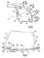
- the figure 1 represents a projector block 2 comprising a light projector 4 and a projector holder 6.
- This projector block 2 is intended for the front of a motor vehicle of which only the front shield 8 is shown.
- the latter is for example fixed in known manner at the body of the vehicle by its lateral extremities and at the front crossbar by its median part.
- the shield 8 has a substantially horizontal upper edge 10 visible on the figure 4 , secured to a substantially vertical wall 12.
- the projector 4 comprises an external mirror 14 comprising a front wall 16 and a substantially horizontal lower edge 18 in the mounted position ( figure 4 ).
- the outer glass 14 is hermetically secured to a housing 20 having a rear base 22 and a base 24 substantially horizontal.
- the lower edge is located in a plane above the base 24.
- the "lower face of the projector" is the lower edge 18 of the window 14 and the base 24 of the housing 20.
- the underside of the projector may be formed solely of the base 24 of the housing, for example when the ice 14 has no lower edge 18.
- the projector 4 comprises at least two fastening tabs 26 on fixed parts of the vehicle.
- three fastening lugs 26 integral with the housing 20 are provided.
- the housing 20 also has at least two brackets 27 on the projector support 6, located near its base 24 ( figure 3 ). These lugs 26, 27 comprise an orifice for fixing them by screws or the like to the vehicle or the support.
- the tabs 26 are for example fixed on the upper front cross member and on the vehicle body (not shown).
- the base 24 of the projector also has positioning means with respect to the projector support 6.
- These positioning means consist of at least two housings 28, only one of which is visible on the figure 4 . They are oriented in the same direction, for example in the longitudinal direction of the vehicle, and are able to cooperate with corresponding tabs disposed on the support 6.
- the projector support 6 is described with reference to the figure 2 . It comprises a body 30 adapted to receive and support at least partly the underside of the projector.
- the body 30 supports the base 24 of the projector. Its shape is therefore substantially complementary to the shape of the base 24.
- Two tongues 32 cut in the thickness of the body 30 and protruding above its surface, form positioning means of the projector. They are designed so that they can be engaged in the slots 28 of the base 24 of the projector ( figure 3 ).
- the tongues 32 are engaged in the recesses 28 in the longitudinal direction of the vehicle, towards the front of the latter.
- the body 30 is provided with shield support means 34 for at least partially supporting the upper edge 10 of the shield.
- these means comprise lugs 36, rigidly secured to the periphery of the body 30, and each having a substantially flat upper bearing surface 38.
- the tabs 36 are shaped so that when the projector is in place on the support 6, the bearing surfaces 38 extend at a substantially constant distance d below the underside of the projector in a substantially vertical direction. ( figure 3 ).
- These bearing surfaces 38 serve to support the edge 10 of the shield, as shown in FIG. figure 4 .
- the largest dimension of these bearing surfaces 38 extends along the periphery of the body 30.
- the tabs 36 preferably extend along and below the visible portion 40 of the edge of the lower face of the projector 4. They are preferably distributed regularly along this length. part 40, but can form a single continuous leg along it.
- the body 30 also comprises means for fixing the headlamp, such as, for example, fixing lugs 42 provided with orifices arranged on the rear part of the body 30 ( figure 2 ). These lugs 42 are fixed to the lugs 27 of the headlamp, by screwing or the like ( figure 3 ).
- the body 30 also has fastening means on fixed parts of the vehicle. These means comprise, for example, at least one leg 44 substantially horizontal or vertical provided with an orifice, and fixed on the upper lateral part of the vehicle body (not shown). They also comprise at least one lug 46 located on the underside of the body 30, parallel to the latter ( figure 4 ), away from the tab 44.
- This lug 46 is fixed on a lower fixed part of the vehicle.
- the lug 46 is fixed to a longitudinal member 48 of the vehicle via a piece 50 in the shape of an inverted L.
- the small wing of the piece 50 is thus inserted between the tab 46 and the body 30 and fixed thereto by means of a screw 52 or the like, while the large wing of the piece 50 is fixed to the spar 48 by means of of a screw 54 or the like.
- the tabs 44 and 46 thus ensure a good attachment of the projector support 6 relative to the vehicle, and limit the transmission of forces to the projector.
- the shield support means 34 comprise a tab 36, as described with reference to the figure 2 and tabs 36 'extending in a substantially vertical direction.
- the bearing surfaces 38 'of the shield are then formed by the upper edge of the tabs 36' and are substantially flat surfaces whose largest dimension extends perpendicularly to the periphery of the body.
- some tabs 36 ' may optionally be interconnected by material bridges (not shown).
- legs 36 or 36 'spaced allows to provide spaces for passing equipment of the vehicle.
- a trim member 56 may be attached to the upper edge 10 of the shield ( figures 1 and 4 ). Vertical fastening screws or clips of this hubcap on the shield are then arranged between the tabs 36 or 36 '. Such hubcap member at least partially obturates the distance d between the shield and the projector, for aesthetic purposes.
- the shield support means 34 are configured so that, when the projector is fixed on the support 6 and the shield 8 rests on the tabs 36, 36 ', spaces d1 and d2 are respectively formed between the front wall 12 of the shield and the foremost part of the legs 36, 36 ', and between the end 58 of the upper edge of the shield and the projector, in a direction substantially perpendicular to the periphery of the body of the support ( figure 4 ).
- These spaces make it possible, during weak shocks, to prevent the shield from damaging the support and the projector. They are for example chosen to withstand shocks of the order of 4 Km / h, and may, for example, be about 15 mm.
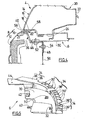
- a space d2 makes it possible, once the fastening tabs 27 and 26 of the headlamp have been detached, to move the projector 4 from the distance d2 in the direction of the tongues 32 towards the front of the vehicle. as represented by the arrows F on the figure 3 .
- the new position of the projector 4, shown in dashed lines in this figure, makes it possible to free a space on the bottom side 22 of the projector housing, and to access more easily either the projector or other elements of the vehicle arranged behind the projector. projector.
- the mounting of the headlamp unit and the shield is carried out as follows.
- the projector support 6 is first attached to the vehicle by means of the brackets 44 and 46. The spacing between them ensures a very stable attachment of the support.
- the shield 8 is then put in place, its upper edge 10 resting on the shield support means 34 of the support 6.
- a trim element 56 may be fixed on the upper edge 10.
- the projector 4 is then placed on the support of projector 6 so that the housing 28 of the base of the projector are aligned with the tongues 32 of the support 6. The latter are then engaged in the housing 28.
- the projector 4 is finally fixed on the support by means of the brackets 27 and on the vehicle by means of the fixing lugs 26.
- the means for positioning the support relative to the projector can be provided.
- the tabs can be arranged on the projector.
- the number and position of the various fastening tabs may also vary depending on the structure of each vehicle.
Abstract
Description
L'invention concerne un bloc projecteur comportant un projecteur et un support de projecteur, le véhicule automobile comportant notamment un bouclier. Elle concerne également un véhicule équipé d'un tel bloc projecteur. Le bloc projecteur selon l'invention est notamment destiné à l'avant d'un véhicule.The invention relates to a projector block comprising a projector and a projector support, the motor vehicle including a shield. It also relates to a vehicle equipped with such a projector block. The projector block according to the invention is particularly intended for the front of a vehicle.
Plusieurs dispositifs de fixation des projecteurs avant existent actuellement.Several front projector attachment devices currently exist.
Un premier dispositif consiste à fixer sur la traverse avant du véhicule une pièce de forme complexe sur laquelle la partie avant de la face inférieure du projecteur va pouvoir être fixée, la partie arrière du projecteur étant fixée à une structure fixe supérieure du véhicule. Ce dispositif présente toutefois l'inconvénient de nécessiter de nombreux réglages délicats pour une fixation et une orientation correctes des projecteurs. Par ailleurs, le bouclier du véhicule est alors fixé au véhicule par sa partie centrale et ses parties latérales, mais n'est pas soutenu au niveau des projecteurs. Cette absence de soutien peut être gênante pour la résistance du bouclier et des projecteurs lors d'un choc et produit en outre un espace irrégulier inesthétique entre le bouclier et les projecteurs.A first device is to fix on the front cross member of the vehicle a complex shaped part on which the front portion of the underside of the projector can be fixed, the rear part of the projector being fixed to a fixed upper structure of the vehicle. This device, however, has the disadvantage of requiring many delicate settings for proper fixation and orientation of the projectors. Furthermore, the shield of the vehicle is then attached to the vehicle by its central portion and its side parts, but is not supported at the headlights. This lack of support can be troublesome for the resistance of the shield and the projectors during a shock and also produces an unsightly irregular space between the shield and the projectors.
Un autre dispositif consiste à réaliser des faces avant en bloc prémonté comportant le bouclier et les projecteurs solidaires d'une pièce de référence destinée à être fixée sur la structure avant du véhicule, tel que décrit dans le document
Un bloc projecteur selon le preambule de la revendication 1 est connu de
L'invention vise à pallier ces inconvénients en proposant un bloc projecteur pouvant être facilement fixé à un véhicule, sans pour autant faire partie d'une face avant en bloc, et qui procure également un support de bouclier maintenant ce dernier à une distance sensiblement constante du projecteur.The invention aims to overcome these disadvantages by providing a projector block that can be easily attached to a vehicle, without being part of a front face in block, and which also provides a shield support now the latter at a substantially constant distance of the projector.
A cet effet, un premier objet de l'invention concerne un bloc projecteur pour véhicule automobile. Selon les caractéristiques de la revendication 1.For this purpose, a first object of the invention relates to a projector block for a motor vehicle. According to the features of claim 1.
Dans un mode de réalisation, les moyens support de bouclier s'étendent de manière continue sur au moins une partie du pourtour du corps du support. Dans un autre mode de réalisation, les moyens support de bouclier sont régulièrement répartis sur une partie du pourtour du corps du support. Cette dernière configuration permet de faire passer entre les moyens de support des équipements du projecteur, tel qu'un gicleur, ou d'autres éléments du véhicule. Ces modes de réalisation permettent d'obtenir un soutien efficace du bouclier au niveau du projecteur.In one embodiment, the shield support means extends continuously over at least a portion of the periphery of the support body. In another embodiment, the shield support means are regularly distributed over a part of the periphery of the support body. This latter configuration makes it possible to pass between the support means of the projector equipment, such as a nozzle, or other elements of the vehicle. These embodiments provide effective shield support at the projector.
Avantageusement, les moyens support de bouclier s'étendent le long de et en dessous de la partie visible du bord de la face inférieure du projecteur. Un espace constant entre le bouclier et le projecteur est ainsi assuré au niveau de la partie visible du projecteur, améliorant l'esthétique de l'ensemble.Advantageously, the shield support means extend along and below the visible portion of the edge of the underside of the projector. A constant space between the shield and the projector is thus provided at the visible portion of the projector, improving the aesthetics of the assembly.
Dans un mode de réalisation particulier, les moyens support de bouclier présentent au moins une surface d'appui sur laquelle repose le bouclier, qui s'étend sensiblement parallèlement à la face inférieure du projecteur, en dessous de celle-ci.In a particular embodiment, the shield support means have at least one bearing surface on which the shield rests, which extends substantially parallel to the underside of the projector, below it.
Dans une variante, les moyens support de bouclier présentent au moins une patte de support reliée rigidement au corps du support et dont la partie supérieure forme ladite au moins une surface d'appui.In a variant, the shield support means have at least one support lug rigidly connected to the support body and whose upper part forms said at least one bearing surface.
Notamment, ladite au moins une surface d'appui de la patte de support peut être une surface sensiblement plane dont la plus grande dimension s'étend le long du pourtour du corps du support. Un support très stable du bouclier est alors obtenu.In particular, said at least one bearing surface of the support lug may be a substantially flat surface, the largest of which dimension extends along the periphery of the support body. A very stable support of the shield is then obtained.
Dans une autre variante, les moyens support de bouclier présentent une pluralité de pattes de support dont les surfaces d'appui respectives sont des surfaces sensiblement planes dont la plus grande dimension s'étend sensiblement perpendiculairement au pourtour du corps du support.In another variant, the shield support means have a plurality of support lugs whose respective bearing surfaces are substantially flat surfaces whose largest dimension extends substantially perpendicular to the periphery of the support body.
Dans une variante, on peut combiner les deux types de surfaces d'appui qui viennent d'être décrites en fonction de l'encombrement.In a variant, it is possible to combine the two types of bearing surfaces which have just been described as a function of the space requirement.
Selon l'invention, le corps du support est pourvu de moyens de positionnement et de fixation du projecteur, et de moyens de fixation sur le véhicule. Les moyens de positionnement et de fixation du projecteur facilitent la mise en place du projecteur sur son support, ce qui permet de réduire le temps de montage et de limiter les réglages.According to the invention, the body of the support is provided with means for positioning and fixing the headlamp, and fastening means on the vehicle. The positioning and fixing means of the projector facilitate the placement of the projector on its support, which reduces the assembly time and limit adjustments.
En particulier, les moyens de positionnement et de fixation comprennent des languettes de positionnement aptes à être insérées dans des parties correspondantes de la face inférieure du projecteur et des languettes de fixation aptes à être fixées rigidement sur la face inférieure du projecteur au niveau de sa partie arrière. Il suffit ainsi de désolidariser les languettes de fixation pour déplacer le projecteur par rapport à son support puis pour le retirer totalement du support. Ce déplacement peut être utilisé avantageusement lors du changement des ampoules du projecteur, pour faciliter l'accès à ces dernières sans démonter entièrement le projecteur de son support.In particular, the positioning and fixing means comprise positioning tongues adapted to be inserted in corresponding parts of the lower face of the projector and fixing tongues adapted to be fixed rigidly on the lower face of the projector at its part. back. It is thus sufficient to separate the fixing tabs to move the projector relative to its support and then to remove it completely from the support. This displacement can be used advantageously when changing the bulbs of the projector, to facilitate access to the latter without completely disassemble the projector of its support.
Un autre objet de l'invention concerne un véhicule comportant un bouclier présentant un bord supérieur sensiblement horizontal solidaire d'une paroi sensiblement verticale et un bloc projecteur selon l'invention.Another object of the invention relates to a vehicle comprising a shield having a substantially horizontal upper edge secured to a substantially vertical wall and a projector block according to the invention.
Avantageusement, les moyens de fixation du support de projecteur sur le véhicule comprennent au moins une patte de fixation sur une structure fixe supérieure du véhicule et au moins une patte de fixation sur une structure fixe inférieure du véhicule. Cette fixation en deux points de la structure assure une bonne stabilité au support de projecteur.Advantageously, the fixing means of the projector support on the vehicle comprise at least one bracket on a fixed upper structure of the vehicle and at least one bracket on a lower fixed structure of the vehicle. This two-point fixation of the structure ensures a good stability to the projector support.
Avantageusement, le véhicule comportant un longeron formant une structure fixe inférieure, ladite au moins une patte de fixation est reliée au longeron par une pièce en forme de L renversé, dont la petite aile est solidarisée à ladite au moins une patte de fixation et la grande aile est solidarisée au longeron.Advantageously, the vehicle comprising a spar forming a lower fixed structure, said at least one fixing lug is connected to the spar by an inverted L-shaped part, the small part of which wing is secured to said at least one bracket and the large wing is secured to the spar.
Dans une variante, un élément enjoliveur est fixé sur le bord supérieur du bouclier de façon à obturer l'espace entre le bouclier et le projecteur dans la direction verticale, afin d'améliorer l'esthétique de l'avant du véhicule.Alternatively, a hubcap element is fixed on the upper edge of the shield so as to close the space between the shield and the projector in the vertical direction, to improve the aesthetics of the front of the vehicle.
Selon l'invention, les moyens support de bouclier sont conformés de manière à être à une distance prédéterminée de la paroi avant du bouclier suivant une direction sensiblement perpendiculaire au pourtour du corps du support dans un plan sensiblement horizontal, et de manière à être à une distance prédéterminée du projecteur suivant la même direction de sorte que le bord du bouclier soit distant du projecteur. Cette configuration présente plusieurs avantages. Les espaces entre la paroi avant du bouclier et le support d'une part, et entre le bord du bouclier et le projecteur d'autre part permettent au bouclier de se déplacer lors de faibles chocs sans pour autant endommager le support et/ou le projecteur. L'espace entre le bord du bouclier et le projecteur joue le rôle d'un espace de débattement du projecteur : ce dernier peut ainsi être avancé jusqu'aux moyens support de bouclier, libérant ainsi de la place sur sa face arrière, par exemple, pour changer les ampoules ou d'autres éléments.According to the invention, the shield support means are shaped so as to be at a predetermined distance from the front wall of the shield in a direction substantially perpendicular to the periphery of the support body in a substantially horizontal plane, and so as to be at a distance from predetermined distance from the projector in the same direction so that the edge of the shield is distant from the projector. This configuration has several advantages. The spaces between the front wall of the shield and the support on the one hand, and between the edge of the shield and the projector on the other hand allow the shield to move during weak impacts without damaging the support and / or the projector . The space between the edge of the shield and the projector plays the role of a clearance space of the projector: the latter can be advanced to the shield support means, thus freeing up space on its rear face, for example, to change bulbs or other items.
L'invention est maintenant décrite en référence aux dessins annexés, non limitatifs, dans lesquels :
- la
figure 1 est une vue en perspective éclatée d'un bloc projecteur selon l'invention et d'un bouclier de véhicule ; - la
figure 2 est une vue en perspective de la face supérieure d'un support de projecteur ; - la
figure 3 est une vue en coupe selon la ligne A-A des éléments de lafigure 1 , sans le bouclier, en position montée ; - la
figure 4 est une vue en coupe selon la ligne B-B des éléments de lafigure 1 en position montée ; - la
figure 5 est une représentation similaire à lafigure 2 d'un autre mode de réalisation d'un support de projecteur.
- the
figure 1 is an exploded perspective view of a projector block according to the invention and a vehicle shield; - the
figure 2 is a perspective view of the upper face of a projector bracket; - the
figure 3 is a sectional view along line AA of the elements of thefigure 1 , without the shield, in the mounted position; - the
figure 4 is a sectional view along line BB of the elements of thefigure 1 in mounted position; - the
figure 5 is a representation similar to thefigure 2 another embodiment of a projector support.
La
Le bouclier 8 présente un bord supérieur 10 sensiblement horizontal, visible sur la
Le projecteur 4 comprend une glace externe 14 comprenant une paroi avant 16 et un bord inférieur 18 essentiellement horizontal en position montée (
Dans la suite du texte, on appelle "face inférieure du projecteur" le bord inférieur 18 de la glace 14 et la base 24 du boîtier 20. Dans des variantes non représentées, la face inférieure du projecteur peut être formée uniquement de la base 24 du boîtier, par exemple lorsque la glace 14 ne présente pas de bord inférieur 18.In the remainder of the text, the "lower face of the projector" is the
Le projecteur 4 comprend au moins deux pattes de fixation 26 sur des parties fixes du véhicule. Dans le mode de réalisation représenté, trois pattes de fixation 26 solidaires du boîtier 20 sont prévues. De manière similaire, le boîtier 20 présente également au moins deux pattes de fixation 27 sur le support de projecteur 6, situées à proximité de sa base 24 (
La base 24 du projecteur présente également des moyens de positionnement par rapport au support de projecteur 6. Ces moyens de positionnement consistent en au moins deux logements 28, dont un seul est visible sur la
Le support de projecteur 6 est décrit en référence à la
Le corps 30 est pourvu de moyens support de bouclier 34 destinés à supporter au moins partiellement le bord supérieur 10 du bouclier.The
Dans le mode de réalisation représenté sur les
Afin d'assurer un maintien correct du bouclier, les pattes 36 s'étendent de préférence le long, et en dessous, de la partie visible 40 du bord de la face inférieure du projecteur 4. Elles sont de préférence réparties régulièrement le long de cette partie 40, mais peuvent former une seule patte continue le long de celle-ci.In order to ensure proper retention of the shield, the
Le corps 30 comprend par ailleurs des moyens de fixation du projecteur, tel que par exemple des pattes de fixation 42 pourvues d'orifices disposées sur la partie arrière du corps 30 (
Enfin, le corps 30 présente également des moyens de fixation sur des parties fixes du véhicule. Ces moyens comprennent, par exemple, au moins une patte 44 sensiblement horizontale ou verticale pourvue d'un orifice, et fixée sur la partie latérale supérieure de la caisse du véhicule (non représentée). Ils comprennent également au moins une patte 46 située sur le dessous du corps 30, parallèlement à ce dernier (
Cette patte 46 est fixée sur une partie fixe inférieure du véhicule. Dans l'exemple représenté, la patte 46 est fixée sur un longeron 48 du véhicule par l'intermédiaire d'une pièce 50 en forme de L renversé. La petite aile de la pièce 50 est ainsi insérée entre la patte 46 et le corps 30 et fixée à ceux-ci au moyen d'une vis 52 ou analogue, tandis que la grande aile de la pièce 50 est fixée au longeron 48 au moyen d'une vis 54 ou analogue.This
Les pattes 44 et 46 assurent ainsi une bonne fixation du support de projecteur 6 par rapport au véhicule, et limitent la transmission d'efforts au projecteur.The
Dans le mode de réalisation représenté sur la
La réalisation de pattes 36 ou 36' espacées permet de ménager des espaces pour laisser passer des équipements du véhicule.The realization of
Par exemple, un élément enjoliveur 56 peut être fixé sur le bord supérieur 10 du bouclier (
Les moyens support de bouclier 34 sont configurés de manière à ce que, lorsque le projecteur est fixé sur le support 6 et que le bouclier 8 repose sur les pattes 36, 36', des espaces d1 et d2 soient ménagés respectivement, entre la paroi avant 12 du bouclier et la partie la plus en avant des pattes 36, 36', et entre l'extrémité 58 du bord supérieur du bouclier et le projecteur, suivant une direction sensiblement perpendiculaire au pourtour du corps du support (
Par ailleurs, l'existence d'un espace d2 permet, une fois que les pattes de fixation 27 et 26 du projecteur ont été désolidarisées, de déplacer de la distance d2 le projecteur 4 suivant la direction des languettes 32 vers l'avant du véhicule, tel que représenté par les flèches F sur la
Le montage du bloc projecteur et du bouclier est réalisé de la manière suivante.The mounting of the headlamp unit and the shield is carried out as follows.
Le support de projecteur 6 est d'abord fixé au véhicule au moyen des pattes de fixations 44 et 46. L'écartement entre ces dernières permet d'assurer une fixation très stable du support. Le bouclier 8 est ensuite mis en place, son bord supérieur 10 reposant sur les moyens support de bouclier 34 du support 6. Eventuellement, un élément enjoliveur 56 peut être fixé sur le bord supérieur 10. Le projecteur 4 est ensuite placé sur le support de projecteur 6 de manière à ce que les logements 28 de la base du projecteur soient alignés avec les languettes 32 du support 6. Ces dernières sont alors engagées dans les logements 28. Le projecteur 4 est enfin fixé sur le support au moyen des pattes de fixation 27 et sur le véhicule au moyen des pattes de fixation 26.The
Il est alors facile et rapide de démonter et remonter rapidement le projecteur grâce aux moyens de positionnement et au faible nombre de pattes de fixation. Il n'est plus nécessaire d'effectuer des réglages à chaque opération de manipulation du projecteur, dès lors que le support est mis en place.It is then easy and quick to quickly disassemble and reassemble the projector thanks to the positioning means and the small number of fixing lugs. It is no longer necessary to make adjustments to each operation of handling the projector, as soon as the support is put in place.
Bien entendu, on peut prévoir d'autres modes de réalisation des moyens de positionnement du support par rapport au projecteur. Par exemple, les pattes peuvent être disposées sur le projecteur. Le nombre et la position des diverses pattes de fixation peuvent également varier en fonction de la structure de chaque véhicule.Of course, other embodiments of the means for positioning the support relative to the projector can be provided. For example, the tabs can be arranged on the projector. The number and position of the various fastening tabs may also vary depending on the structure of each vehicle.
Claims (13)
- Headlamp unit (2) for a motor vehicle, comprising a headlamp (4) having an underside and a headlamp support (6), the said vehicle comprising a bumper (8) exhibiting a substantially horizontal upper edge (10) with one end (58) and secured to a substantially vertical front wall (12), in which
the headlamp support (6) comprises a body (30) accepting and supporting, at least in part, the underside of the headlamp, the said body being provided with bumper support means (34) able at least partially to support the said upper edge (10) of the bumper under the underside of the headlamp, at a substantially constant distance (d) from the said underside in a substantially vertical direction, the said headlamp unit (2) comprising means (44, 46, 26) of attachment to the vehicle, and in which,
the body (30) of the support is provided with headlamp positioning (32) and attachment (42) means and with means (44, 46) of attachment to the vehicle,
characterized in that the bumper support means (34) are shaped in such a way as to lie a predetermined distance (d1) away from the front wall (12) of the bumper in a direction substantially perpendicular to the periphery of the body (30) of the support in a substantially horizontal plane, and in such a way as to lie a predetermined distance away from the headlamp in the same direction so that the end (58) of the upper edge (10) of the bumper is at a distance (d2) from the headlamp (4) thus allowing movement of the bumper and of the headlamp. - Headlamp unit according to Claim 1, characterized in that the bumper support means (34) extend continuously over at least part of the periphery of the body (30) of the support.
- Headlamp unit according to Claim 1, characterized in that the bumper support means (34) are evenly distributed over part of the periphery of the body (30) of the support.
- Headlamp unit according to one of Claims 1 to 3, characterized in that the bumper support means (34) extend along and under the visible part (40) of the edge of the underside of the headlamp.
- Headlamp unit according to one of Claims 1 to 4, characterized in that the bumper support means (34) have at least one bearing surface (38, 38') against which the bumper rests, which extends substantially parallel to the underside of the headlamp, beneath the latter.
- Headlamp unit according to Claim 5, characterized in that the bumper support means (34) have at least one support tab (36, 36') rigidly connected to the body of the support and the upper part of which forms the said at least one bearing surface (38, 38').
- Headlamp unit according to Claim 6, characterized in that the said at least one bearing surface (38) of the support tab (36) is a substantially planar surface the largest dimension of which extends along the periphery of the body of the support.
- Headlamp unit according to Claim 6, characterized in that the bumper support means (34) have a plurality of support tabs (36') of which the respective bearing surfaces (38') are substantially planar surfaces the largest dimension of which extends substantially perpendicular to the periphery of the body of the support.
- Headlamp unit according to one of Claims 1 to 7, characterized in that the positioning and attachment means comprise positioning tongues (32) able to be inserted in corresponding parts (28) of the underside of the headlamp and attachment tongues (42) able to be rigidly attached to the underside of the headlamp at the rear part thereof.
- Vehicle comprising a bumper (8) having a substantially horizontal upper edge (10) secured to a substantially vertical front wall (12) and a headlamp unit (2) according to one of Claims 1 to 9.
- Vehicle according to Claim 10, characterized in that the means of attaching the headlamp support to the vehicle comprise at least one attachment tab (44) for attachment to an upper fixed structure of the vehicle and at least one attachment tab (46) for attachment to a lower fixed structure of the vehicle.
- Vehicle according to Claim 11, the said vehicle comprising a beam (48) forming a lower fixed structure, characterized in that the said at least one attachment tab (46) is connected to the beam (48) by an inverted-L-shaped component (50) of which the shorter leg is secured to the said at least one attachment tab (46) and of which the longer leg is secured to the beam (48).
- Vehicle according to one of Claims 10 to 12, characterized in that a trim element (56) is attached to the upper edge (10) of the bumper to conceal the space between the bumper and the headlamp in the vertical direction.
Applications Claiming Priority (2)
| Application Number | Priority Date | Filing Date | Title |
|---|---|---|---|
| FR0308609A FR2857645B1 (en) | 2003-07-15 | 2003-07-15 | PROJECTOR BLOCK FOR MOTOR VEHICLE, AND CORRESPONDING VEHICLE. |
| PCT/FR2004/001741 WO2005007449A1 (en) | 2003-07-15 | 2004-07-05 | Headlight block for motor vehicle and corresponding vehicle |
Publications (2)
| Publication Number | Publication Date |
|---|---|
| EP1644219A1 EP1644219A1 (en) | 2006-04-12 |
| EP1644219B1 true EP1644219B1 (en) | 2009-08-26 |
Family
ID=33548136
Family Applications (1)
| Application Number | Title | Priority Date | Filing Date |
|---|---|---|---|
| EP04767577A Not-in-force EP1644219B1 (en) | 2003-07-15 | 2004-07-05 | Headlight block for motor vehicle and corresponding vehicle |
Country Status (6)
| Country | Link |
|---|---|
| EP (1) | EP1644219B1 (en) |
| JP (1) | JP4614211B2 (en) |
| AT (1) | ATE440752T1 (en) |
| DE (1) | DE602004022814D1 (en) |
| FR (1) | FR2857645B1 (en) |
| WO (1) | WO2005007449A1 (en) |
Cited By (1)
| Publication number | Priority date | Publication date | Assignee | Title |
|---|---|---|---|---|
| DE102020121799A1 (en) | 2020-08-19 | 2022-02-24 | Bayerische Motoren Werke Aktiengesellschaft | Connecting element for connecting a headlight unit to a bumper cover, front unit and vehicle |
Families Citing this family (18)
| Publication number | Priority date | Publication date | Assignee | Title |
|---|---|---|---|---|
| DE102004012551B4 (en) * | 2004-03-15 | 2018-06-14 | Volkswagen Ag | Device for fastening a vehicle headlight and an attachment |
| FR2873652B1 (en) * | 2004-08-02 | 2008-01-25 | Faurecia Bloc Avant | FRONT ASSEMBLY OF A MOTOR VEHICLE |
| DE102005009926B4 (en) * | 2005-03-04 | 2018-11-08 | Volkswagen Ag | Mounting arrangement for a bumper cover on a vehicle |
| DE102005045086A1 (en) * | 2005-09-21 | 2007-04-12 | Volkswagen Ag | Fastening device for e.g. bumper light assembly, has cross unit with light fastening unit for fastening housing of light to cross unit, and bumper fastening unit coupled with housing, where bumper is fastened to bumper fastening unit |
| FR2891798B1 (en) * | 2005-10-06 | 2009-05-01 | Plastic Omnium Cie | SUPPORT FOR OPTICAL BLOCK OF MOTOR VEHICLE. |
| DE102006023803A1 (en) * | 2006-05-20 | 2007-11-22 | GM Global Technology Operations, Inc., Detroit | Bumper arrangement in or for a motor vehicle |
| FR2903646B1 (en) * | 2006-07-13 | 2009-04-17 | Peugeot Citroen Automobiles Sa | DEVICE FOR POSITIONING BODYWORK ELEMENTS OF A FRONT PANEL OF A MOTOR VEHICLE AND MOTOR VEHICLE COMPRISING SUCH A FRONT PANEL. |
| DE102007008489A1 (en) * | 2007-02-19 | 2008-09-04 | Hbpo Gmbh | Front end module for vehicles |
| DE102007035279A1 (en) * | 2007-07-27 | 2009-01-29 | Audi Ag | Headlight attaching device for motor vehicle, has retaining unit moving against body part by determined force that exceeds during frontal impact, and reinforcement unit indirectly connected with body part of vehicle body |
| JP5075557B2 (en) * | 2007-09-28 | 2012-11-21 | スタンレー電気株式会社 | Vehicle lamp mounting structure for vehicle lamps |
| FR2923433B1 (en) * | 2007-11-12 | 2010-04-23 | Faurecia Bloc Avant | BUMPER SKIN FOR A FRONT MODULE OF A MOTOR VEHICLE AND A MOTOR VEHICLE THEREFOR |
| DE102008024428A1 (en) * | 2008-05-20 | 2009-11-26 | Dr. Ing. H.C. F. Porsche Aktiengesellschaft | Component assembly for mounting headlamp in area of recess of mudguard of motor vehicle, has headlamp pot which consists of receiving plate for mounting headlamp and reinforcement element which is connected with receiving plate |
| FR2951675A1 (en) * | 2009-10-28 | 2011-04-29 | Peugeot Citroen Automobiles Sa | Rear part for motor vehicle, has intermediate support extended between under-light support and lateral support to support upper edge of each of lateral parts of bumper, where upper edge is fixed to under-light support and lateral support |
| DE102013210981A1 (en) * | 2013-06-12 | 2014-12-18 | Bayerische Motoren Werke Aktiengesellschaft | joint assembly |
| DE102014005060A1 (en) * | 2014-04-05 | 2015-10-08 | Daimler Ag | Bumper cover for a motor vehicle |
| FR3040666B1 (en) * | 2015-09-03 | 2021-02-19 | Peugeot Citroen Automobiles Sa | OPTICAL BLOCK FOR AUTOMOTIVE VEHICLES CONTAINING A BOX FITTED WITH BUMPER SKIN SUPPORT ORGANS. |
| FR3094293B1 (en) * | 2019-03-29 | 2021-03-05 | Psa Automobiles Sa | Device and method for isostatic mounting on the body of a motor vehicle, a light projector and a bumper mounted on a common support. |
| FR3118132A1 (en) | 2020-12-22 | 2022-06-24 | Psa Automobiles Sa | PROTECTION DEVICE AGAINST IMPACTS WITH INTEGRATED OPTICAL BLOCK IN CONSTRAINED ENVIRONMENT, FOR A VEHICLE |
Family Cites Families (11)
| Publication number | Priority date | Publication date | Assignee | Title |
|---|---|---|---|---|
| FR2481218A1 (en) * | 1980-04-25 | 1981-10-30 | Peugeot | Vehicle body end section - has weakened breakage portion between bracing panel and integral bumper |
| DE4142582A1 (en) * | 1991-12-21 | 1993-06-24 | Porsche Ag | BUMPER FOR VEHICLES, IN PARTICULAR MOTOR VEHICLES |
| JP3151587B2 (en) * | 1994-06-03 | 2001-04-03 | 日産車体株式会社 | Positioning structure between headlamp and front bumper |
| JPH0858498A (en) * | 1994-08-24 | 1996-03-05 | Daihatsu Motor Co Ltd | Support structure of bumper for vehicle |
| FR2783797B1 (en) | 1998-09-30 | 2000-12-29 | Ecia Equip Composants Ind Auto | MOTOR VEHICLE, FRONT BLOCK FOR THIS VEHICLE AND METHOD OF MOUNTING THE VEHICLE |
| JP4066061B2 (en) * | 1999-05-27 | 2008-03-26 | 関東自動車工業株式会社 | Bumper mounting structure |
| JP2001225708A (en) * | 2000-02-16 | 2001-08-21 | Koito Mfg Co Ltd | Lighting fixture and bumper connection structure for vehicle |
| FR2820706B1 (en) * | 2001-02-15 | 2003-05-16 | Faurecia Ind | FRONT BLOCK ASSEMBLY OF A MOTOR VEHICLE COMPRISING AN IMPROVED DEVICE FOR FIXING THE COMPONENTS, AND VEHICLE PROVIDED WITH SUCH AN ASSEMBLY |
| FR2827251B1 (en) | 2001-07-10 | 2003-10-31 | Peguform France | VEHICLE COMPRISING A PART FOR HOLDING BODY ELEMENTS OF THE FRONT OF THE VEHICLE |
| FR2852285B1 (en) * | 2003-03-11 | 2005-06-10 | Peugeot Citroen Automobiles Sa | METHOD AND ASSEMBLY FOR MOUNTING A BUMPER AND AT LEAST ONE LIGHTING DEVICE OF A MOTOR VEHICLE IN ADJACENT POSITIONS |
| FR2855487B1 (en) * | 2003-06-02 | 2005-08-26 | Faurecia Ind | AUTOMOTIVE VEHICLE FRONT BLOCK ASSEMBLY COMPRISING SELF-ADJUSTING MEANS FOR THE POSITION OF THE OPTICAL BLOCKS, REMOVABLE ADJUSTABLE PLATFORM FOR THE SAME, AND METHOD OF MOUNTING SUCH A FRONT BLOCK |
-
2003
- 2003-07-15 FR FR0308609A patent/FR2857645B1/en not_active Expired - Fee Related
-
2004
- 2004-07-05 EP EP04767577A patent/EP1644219B1/en not_active Not-in-force
- 2004-07-05 DE DE602004022814T patent/DE602004022814D1/en active Active
- 2004-07-05 WO PCT/FR2004/001741 patent/WO2005007449A1/en active Application Filing
- 2004-07-05 JP JP2006519950A patent/JP4614211B2/en not_active Expired - Fee Related
- 2004-07-05 AT AT04767577T patent/ATE440752T1/en not_active IP Right Cessation
Cited By (1)
| Publication number | Priority date | Publication date | Assignee | Title |
|---|---|---|---|---|
| DE102020121799A1 (en) | 2020-08-19 | 2022-02-24 | Bayerische Motoren Werke Aktiengesellschaft | Connecting element for connecting a headlight unit to a bumper cover, front unit and vehicle |
Also Published As
| Publication number | Publication date |
|---|---|
| JP2007516119A (en) | 2007-06-21 |
| EP1644219A1 (en) | 2006-04-12 |
| DE602004022814D1 (en) | 2009-10-08 |
| FR2857645B1 (en) | 2005-09-16 |
| FR2857645A1 (en) | 2005-01-21 |
| WO2005007449A1 (en) | 2005-01-27 |
| JP4614211B2 (en) | 2011-01-19 |
| ATE440752T1 (en) | 2009-09-15 |
Similar Documents
| Publication | Publication Date | Title |
|---|---|---|
| EP1644219B1 (en) | Headlight block for motor vehicle and corresponding vehicle | |
| EP0720935B1 (en) | Device for precise positioning of a bumper to a vehicle fender portion | |
| EP1232932B1 (en) | Front module for vehicle with improved fixation device for componants, and vehicle equipped with such a device | |
| EP1623879B1 (en) | Front end module of motor vehicle | |
| EP1544035A1 (en) | Vehicle body front portion assembly with improved fastening and position adjusting means, and vehicle provided with such an assembly | |
| EP1634800B1 (en) | Front module for vehicle | |
| EP1773648A1 (en) | Motor vehicle font unit | |
| EP2766220A1 (en) | Holder for an automobile headlight, and corresponding headlight | |
| EP2102032B1 (en) | Arrangement of support means for a motor vehicle bumper | |
| WO2003006302A1 (en) | Vehicle comprising a piece for supporting a car body element at the front of a vehicle | |
| EP1216913A1 (en) | Automotive vehicle front end made of three parts and comprising a cooling module | |
| EP1758767B1 (en) | Headlight block for a motor vehicle | |
| EP1877285B1 (en) | Arrangement for motor vehicle shock absorber | |
| EP3360442B1 (en) | Arrangement system provided with an element and a counter-element | |
| EP1127740B1 (en) | Vehicle headlight with mask and reflector | |
| EP1475268B1 (en) | Arrangement for positioning and fastening an equipment element in a motor vehicle | |
| EP1252045B1 (en) | Device for fixing bumper guards | |
| EP3381747A1 (en) | Device for attaching a headlight to a vehicle | |
| EP1127741B1 (en) | Vehicle headlamp with mask and correction | |
| EP1610005B1 (en) | Clip for the attachment of a screw to parts of an automobile | |
| FR3062367B1 (en) | DASHBOARD TRAVERSE AND MODULAR STEERING COLUMN SUPPORT CONSOLE | |
| FR2917057A1 (en) | Dashboard module for motor vehicle, has air conditioner maintenance unit comprising housing that retains pre-fixation element so as to stop movement of air conditioner with respect to dashboard crosspiece | |
| FR2796535A1 (en) | Adjustable height shelves support comprises two opposite racks with crenellations separated by grooves with batten between and engaging racks | |
| WO2020225491A1 (en) | Daytime signaling module for motor vehicles and lighting and signaling assembly comprising said module | |
| FR2737987A1 (en) | DEVICE FOR QUICK FIXING OF A SUN VISOR ON A VEHICLE |
Legal Events
| Date | Code | Title | Description |
|---|---|---|---|
| PUAI | Public reference made under article 153(3) epc to a published international application that has entered the european phase |
Free format text: ORIGINAL CODE: 0009012 |
|
| 17P | Request for examination filed |
Effective date: 20060110 |
|
| AK | Designated contracting states |
Kind code of ref document: A1 Designated state(s): AT BE BG CH CY CZ DE DK EE ES FI FR GB GR HU IE IT LI LU MC NL PL PT RO SE SI SK TR |
|
| DAX | Request for extension of the european patent (deleted) | ||
| 17Q | First examination report despatched |
Effective date: 20070619 |
|
| GRAP | Despatch of communication of intention to grant a patent |
Free format text: ORIGINAL CODE: EPIDOSNIGR1 |
|
| GRAS | Grant fee paid |
Free format text: ORIGINAL CODE: EPIDOSNIGR3 |
|
| GRAA | (expected) grant |
Free format text: ORIGINAL CODE: 0009210 |
|
| AK | Designated contracting states |
Kind code of ref document: B1 Designated state(s): AT BE BG CH CY CZ DE DK EE ES FI FR GB GR HU IE IT LI LU MC NL PL PT RO SE SI SK TR |
|
| REG | Reference to a national code |
Ref country code: GB Ref legal event code: FG4D Free format text: NOT ENGLISH |
|
| REG | Reference to a national code |
Ref country code: CH Ref legal event code: EP |
|
| REG | Reference to a national code |
Ref country code: IE Ref legal event code: FG4D Free format text: LANGUAGE OF EP DOCUMENT: FRENCH |
|
| REF | Corresponds to: |
Ref document number: 602004022814 Country of ref document: DE Date of ref document: 20091008 Kind code of ref document: P |
|
| PG25 | Lapsed in a contracting state [announced via postgrant information from national office to epo] |
Ref country code: SE Free format text: LAPSE BECAUSE OF FAILURE TO SUBMIT A TRANSLATION OF THE DESCRIPTION OR TO PAY THE FEE WITHIN THE PRESCRIBED TIME-LIMIT Effective date: 20090826 Ref country code: FI Free format text: LAPSE BECAUSE OF FAILURE TO SUBMIT A TRANSLATION OF THE DESCRIPTION OR TO PAY THE FEE WITHIN THE PRESCRIBED TIME-LIMIT Effective date: 20090826 Ref country code: AT Free format text: LAPSE BECAUSE OF FAILURE TO SUBMIT A TRANSLATION OF THE DESCRIPTION OR TO PAY THE FEE WITHIN THE PRESCRIBED TIME-LIMIT Effective date: 20090826 |
|
| NLV1 | Nl: lapsed or annulled due to failure to fulfill the requirements of art. 29p and 29m of the patents act | ||
| PG25 | Lapsed in a contracting state [announced via postgrant information from national office to epo] |
Ref country code: PL Free format text: LAPSE BECAUSE OF FAILURE TO SUBMIT A TRANSLATION OF THE DESCRIPTION OR TO PAY THE FEE WITHIN THE PRESCRIBED TIME-LIMIT Effective date: 20090826 Ref country code: NL Free format text: LAPSE BECAUSE OF FAILURE TO SUBMIT A TRANSLATION OF THE DESCRIPTION OR TO PAY THE FEE WITHIN THE PRESCRIBED TIME-LIMIT Effective date: 20090826 Ref country code: SI Free format text: LAPSE BECAUSE OF FAILURE TO SUBMIT A TRANSLATION OF THE DESCRIPTION OR TO PAY THE FEE WITHIN THE PRESCRIBED TIME-LIMIT Effective date: 20090826 |
|
| PG25 | Lapsed in a contracting state [announced via postgrant information from national office to epo] |
Ref country code: BG Free format text: LAPSE BECAUSE OF FAILURE TO SUBMIT A TRANSLATION OF THE DESCRIPTION OR TO PAY THE FEE WITHIN THE PRESCRIBED TIME-LIMIT Effective date: 20091126 Ref country code: PT Free format text: LAPSE BECAUSE OF FAILURE TO SUBMIT A TRANSLATION OF THE DESCRIPTION OR TO PAY THE FEE WITHIN THE PRESCRIBED TIME-LIMIT Effective date: 20091228 Ref country code: CY Free format text: LAPSE BECAUSE OF FAILURE TO SUBMIT A TRANSLATION OF THE DESCRIPTION OR TO PAY THE FEE WITHIN THE PRESCRIBED TIME-LIMIT Effective date: 20090826 |
|
| REG | Reference to a national code |
Ref country code: IE Ref legal event code: FD4D |
|
| PG25 | Lapsed in a contracting state [announced via postgrant information from national office to epo] |
Ref country code: CZ Free format text: LAPSE BECAUSE OF FAILURE TO SUBMIT A TRANSLATION OF THE DESCRIPTION OR TO PAY THE FEE WITHIN THE PRESCRIBED TIME-LIMIT Effective date: 20090826 Ref country code: ES Free format text: LAPSE BECAUSE OF FAILURE TO SUBMIT A TRANSLATION OF THE DESCRIPTION OR TO PAY THE FEE WITHIN THE PRESCRIBED TIME-LIMIT Effective date: 20091207 Ref country code: EE Free format text: LAPSE BECAUSE OF FAILURE TO SUBMIT A TRANSLATION OF THE DESCRIPTION OR TO PAY THE FEE WITHIN THE PRESCRIBED TIME-LIMIT Effective date: 20090826 Ref country code: DK Free format text: LAPSE BECAUSE OF FAILURE TO SUBMIT A TRANSLATION OF THE DESCRIPTION OR TO PAY THE FEE WITHIN THE PRESCRIBED TIME-LIMIT Effective date: 20090826 Ref country code: IE Free format text: LAPSE BECAUSE OF FAILURE TO SUBMIT A TRANSLATION OF THE DESCRIPTION OR TO PAY THE FEE WITHIN THE PRESCRIBED TIME-LIMIT Effective date: 20090826 Ref country code: RO Free format text: LAPSE BECAUSE OF FAILURE TO SUBMIT A TRANSLATION OF THE DESCRIPTION OR TO PAY THE FEE WITHIN THE PRESCRIBED TIME-LIMIT Effective date: 20090826 |
|
| PG25 | Lapsed in a contracting state [announced via postgrant information from national office to epo] |
Ref country code: SK Free format text: LAPSE BECAUSE OF FAILURE TO SUBMIT A TRANSLATION OF THE DESCRIPTION OR TO PAY THE FEE WITHIN THE PRESCRIBED TIME-LIMIT Effective date: 20090826 |
|
| PLBE | No opposition filed within time limit |
Free format text: ORIGINAL CODE: 0009261 |
|
| STAA | Information on the status of an ep patent application or granted ep patent |
Free format text: STATUS: NO OPPOSITION FILED WITHIN TIME LIMIT |
|
| 26N | No opposition filed |
Effective date: 20100527 |
|
| PG25 | Lapsed in a contracting state [announced via postgrant information from national office to epo] |
Ref country code: GR Free format text: LAPSE BECAUSE OF FAILURE TO SUBMIT A TRANSLATION OF THE DESCRIPTION OR TO PAY THE FEE WITHIN THE PRESCRIBED TIME-LIMIT Effective date: 20091127 |
|
| BERE | Be: lapsed |
Owner name: RENAULT S.A.S. Effective date: 20100731 |
|
| PG25 | Lapsed in a contracting state [announced via postgrant information from national office to epo] |
Ref country code: MC Free format text: LAPSE BECAUSE OF NON-PAYMENT OF DUE FEES Effective date: 20100731 |
|
| REG | Reference to a national code |
Ref country code: CH Ref legal event code: PL |
|
| PG25 | Lapsed in a contracting state [announced via postgrant information from national office to epo] |
Ref country code: IT Free format text: LAPSE BECAUSE OF FAILURE TO SUBMIT A TRANSLATION OF THE DESCRIPTION OR TO PAY THE FEE WITHIN THE PRESCRIBED TIME-LIMIT Effective date: 20090826 |
|
| PG25 | Lapsed in a contracting state [announced via postgrant information from national office to epo] |
Ref country code: LI Free format text: LAPSE BECAUSE OF NON-PAYMENT OF DUE FEES Effective date: 20100731 Ref country code: CH Free format text: LAPSE BECAUSE OF NON-PAYMENT OF DUE FEES Effective date: 20100731 |
|
| PG25 | Lapsed in a contracting state [announced via postgrant information from national office to epo] |
Ref country code: BE Free format text: LAPSE BECAUSE OF NON-PAYMENT OF DUE FEES Effective date: 20100731 |
|
| PG25 | Lapsed in a contracting state [announced via postgrant information from national office to epo] |
Ref country code: LU Free format text: LAPSE BECAUSE OF NON-PAYMENT OF DUE FEES Effective date: 20100705 Ref country code: HU Free format text: LAPSE BECAUSE OF FAILURE TO SUBMIT A TRANSLATION OF THE DESCRIPTION OR TO PAY THE FEE WITHIN THE PRESCRIBED TIME-LIMIT Effective date: 20100227 |
|
| PG25 | Lapsed in a contracting state [announced via postgrant information from national office to epo] |
Ref country code: TR Free format text: LAPSE BECAUSE OF FAILURE TO SUBMIT A TRANSLATION OF THE DESCRIPTION OR TO PAY THE FEE WITHIN THE PRESCRIBED TIME-LIMIT Effective date: 20090826 |
|
| REG | Reference to a national code |
Ref country code: FR Ref legal event code: PLFP Year of fee payment: 12 |
|
| REG | Reference to a national code |
Ref country code: FR Ref legal event code: PLFP Year of fee payment: 13 |
|
| REG | Reference to a national code |
Ref country code: FR Ref legal event code: PLFP Year of fee payment: 14 |
|
| REG | Reference to a national code |
Ref country code: FR Ref legal event code: PLFP Year of fee payment: 15 |
|
| PGFP | Annual fee paid to national office [announced via postgrant information from national office to epo] |
Ref country code: FR Payment date: 20210727 Year of fee payment: 18 |
|
| PGFP | Annual fee paid to national office [announced via postgrant information from national office to epo] |
Ref country code: DE Payment date: 20210721 Year of fee payment: 18 Ref country code: GB Payment date: 20210721 Year of fee payment: 18 |
|
| REG | Reference to a national code |
Ref country code: DE Ref legal event code: R119 Ref document number: 602004022814 Country of ref document: DE |
|
| GBPC | Gb: european patent ceased through non-payment of renewal fee |
Effective date: 20220705 |
|
| PG25 | Lapsed in a contracting state [announced via postgrant information from national office to epo] |
Ref country code: FR Free format text: LAPSE BECAUSE OF NON-PAYMENT OF DUE FEES Effective date: 20220731 |
|
| PG25 | Lapsed in a contracting state [announced via postgrant information from national office to epo] |
Ref country code: GB Free format text: LAPSE BECAUSE OF NON-PAYMENT OF DUE FEES Effective date: 20220705 Ref country code: DE Free format text: LAPSE BECAUSE OF NON-PAYMENT OF DUE FEES Effective date: 20230201 |