EP1548241B1 - Schalldämpfer - Google Patents
Schalldämpfer Download PDFInfo
- Publication number
- EP1548241B1 EP1548241B1 EP03793567A EP03793567A EP1548241B1 EP 1548241 B1 EP1548241 B1 EP 1548241B1 EP 03793567 A EP03793567 A EP 03793567A EP 03793567 A EP03793567 A EP 03793567A EP 1548241 B1 EP1548241 B1 EP 1548241B1
- Authority
- EP
- European Patent Office
- Prior art keywords
- muffler
- gas
- gas flow
- energy
- sensor member
- Prior art date
- Legal status (The legal status is an assumption and is not a legal conclusion. Google has not performed a legal analysis and makes no representation as to the accuracy of the status listed.)
- Expired - Lifetime
Links
Images
Classifications
-
- F—MECHANICAL ENGINEERING; LIGHTING; HEATING; WEAPONS; BLASTING
- F01—MACHINES OR ENGINES IN GENERAL; ENGINE PLANTS IN GENERAL; STEAM ENGINES
- F01N—GAS-FLOW SILENCERS OR EXHAUST APPARATUS FOR MACHINES OR ENGINES IN GENERAL; GAS-FLOW SILENCERS OR EXHAUST APPARATUS FOR INTERNAL-COMBUSTION ENGINES
- F01N1/00—Silencing apparatus characterised by method of silencing
- F01N1/16—Silencing apparatus characterised by method of silencing by using movable parts
- F01N1/166—Silencing apparatus characterised by method of silencing by using movable parts for changing the flow path through the silencer or for adjusting the dimensions of a chamber or a pipe
-
- F—MECHANICAL ENGINEERING; LIGHTING; HEATING; WEAPONS; BLASTING
- F01—MACHINES OR ENGINES IN GENERAL; ENGINE PLANTS IN GENERAL; STEAM ENGINES
- F01N—GAS-FLOW SILENCERS OR EXHAUST APPARATUS FOR MACHINES OR ENGINES IN GENERAL; GAS-FLOW SILENCERS OR EXHAUST APPARATUS FOR INTERNAL-COMBUSTION ENGINES
- F01N1/00—Silencing apparatus characterised by method of silencing
- F01N1/16—Silencing apparatus characterised by method of silencing by using movable parts
- F01N1/161—Silencing apparatus characterised by method of silencing by using movable parts for adjusting resonance or dead chambers or passages to resonance or dead chambers
- F01N1/163—Silencing apparatus characterised by method of silencing by using movable parts for adjusting resonance or dead chambers or passages to resonance or dead chambers by means of valves
-
- F—MECHANICAL ENGINEERING; LIGHTING; HEATING; WEAPONS; BLASTING
- F01—MACHINES OR ENGINES IN GENERAL; ENGINE PLANTS IN GENERAL; STEAM ENGINES
- F01N—GAS-FLOW SILENCERS OR EXHAUST APPARATUS FOR MACHINES OR ENGINES IN GENERAL; GAS-FLOW SILENCERS OR EXHAUST APPARATUS FOR INTERNAL-COMBUSTION ENGINES
- F01N1/00—Silencing apparatus characterised by method of silencing
- F01N1/16—Silencing apparatus characterised by method of silencing by using movable parts
- F01N1/165—Silencing apparatus characterised by method of silencing by using movable parts for adjusting flow area
-
- F—MECHANICAL ENGINEERING; LIGHTING; HEATING; WEAPONS; BLASTING
- F04—POSITIVE - DISPLACEMENT MACHINES FOR LIQUIDS; PUMPS FOR LIQUIDS OR ELASTIC FLUIDS
- F04B—POSITIVE-DISPLACEMENT MACHINES FOR LIQUIDS; PUMPS
- F04B39/00—Component parts, details, or accessories, of pumps or pumping systems specially adapted for elastic fluids, not otherwise provided for in, or of interest apart from, groups F04B25/00 - F04B37/00
- F04B39/0027—Pulsation and noise damping means
- F04B39/0055—Pulsation and noise damping means with a special shape of fluid passage, e.g. bends, throttles, diameter changes, pipes
- F04B39/0061—Pulsation and noise damping means with a special shape of fluid passage, e.g. bends, throttles, diameter changes, pipes using muffler volumes
-
- F—MECHANICAL ENGINEERING; LIGHTING; HEATING; WEAPONS; BLASTING
- F04—POSITIVE - DISPLACEMENT MACHINES FOR LIQUIDS; PUMPS FOR LIQUIDS OR ELASTIC FLUIDS
- F04B—POSITIVE-DISPLACEMENT MACHINES FOR LIQUIDS; PUMPS
- F04B53/00—Component parts, details or accessories not provided for in, or of interest apart from, groups F04B1/00 - F04B23/00 or F04B39/00 - F04B47/00
- F04B53/001—Noise damping
-
- F—MECHANICAL ENGINEERING; LIGHTING; HEATING; WEAPONS; BLASTING
- F04—POSITIVE - DISPLACEMENT MACHINES FOR LIQUIDS; PUMPS FOR LIQUIDS OR ELASTIC FLUIDS
- F04C—ROTARY-PISTON, OR OSCILLATING-PISTON, POSITIVE-DISPLACEMENT MACHINES FOR LIQUIDS; ROTARY-PISTON, OR OSCILLATING-PISTON, POSITIVE-DISPLACEMENT PUMPS
- F04C29/00—Component parts, details or accessories of pumps or pumping installations, not provided for in groups F04C18/00 - F04C28/00
- F04C29/06—Silencing
Definitions
- This invention relates to a muffler, more particularly, to a muffler for eliminating or reducing effectively the gas flow pulsation and the noise caused thereby.
- a muffler is used to reduce noise by utilizing mainly aerodynamic attenuating principle, such as sound absorption, expansion, resonance and so on, the level of researches and development associated with the structures and the principles of the muffler is very high.
- aerodynamic attenuating principle such as sound absorption, expansion, resonance and so on
- the mufflers in these patents are various, but they have a common ground, that is, the structures of the mufflers are unchangeable so that they can't be provided with a mechanism which is capable of realizing self-adjustment automatically with respect to change of the pulsating gas flow, now although there are some adjusting devices provided for them, these devices only can be adjusted manually.
- Sound-deadening characteristic of the mufflers having the unchangeable structure is unchangeable, but variation of pulsation of gas flow is random and the mufflers having the unchangeable structure are therefore always in a passive state in operation, anechoic effect can not be perfect.
- the muffler is normally used to reduce noise of discharging gas of reciprocating engines and gas compressors, which are originated from pulsation of discharging gas.
- Document US 4,903,486 which is considered to represent the closest prior art, discloses a performance responsive muffler, comprising a body having a variable restrictor located downstream from an inlet port and upstream from an outlet port.
- the variable restrictor is formed with a solid wall disposed about the valving element, and defines a constricting annular passageway.
- the valving element consists of a spring, which is located between the restricting wall and a spider, and is located in the gas stream.
- the cross section of the exhaust gas channel may increase or decrease with increasing gas pressure.
- Document US 1,163,128 discloses a muffler intended for use on the exhaust pipe of an internal combustion engine.
- the muffler comprises a chamber which is connected to the exhaust pipe and a valve located in the chamber.
- the valve tends to close under the shock of the explosion, thereby decreasing the force of the discharge, and permitting gradual escape of the gas as the valve resumes its open position after each explosion.
- the object of the invention is to design a muffler which can not only realize self-adjustment with respect to the random change of the pulsating gas flow but eliminate or reduce effectively the gas flow pulsation in low-frequency and medium-frequency and the noise caused thereby.
- the invention is to provide a muffler which comprises a casing within which is a gas inlet, a gas chamber and a gas outlet, a throttling device which is located in gas flow route and controlled by the energy of gas flow to be muffled.
- the muffler according to the invention has significantly advantages and positive effects as follows: 1. It can realize self-adjustment with respect to the random change of the pulsating gas flow. 2.It can eliminate or reduce effectively the pulsation of gas flow in low-frequency and medium-frequency which is difficult to eliminate and the noise caused thereby. 3.It can reduce the volume of the muffler because the anechoic effect is not much dependent on it.
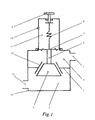
- a muffler casing 14 is divided into a gas inlet chamber 2 communicated with a gas inlet 13 and a gas outlet chamber 4 communicated with a gas outlet 5 by a partition 3, one throttling device is constructed of an open and close component 1 and a fixture 12 on the partition 3, when the open and close component 1 moves upwardly as shown in the figure, the area of the flow cross-section will decrease, whereas it will increase.
- the muffled gas flow flows into the gas chamber 2 through the gas inlet 13, and is throttled by the throttling device and into the outlet chamber 4, then discharges from the gas outlet 5.
- the energy sensor member 7 is a diaphragm in this embodiment and sensible for potential energy of the muffled gas flow chiefly.
- the energy sensor member 7 also can be selected from a piston, a bellows etc.
- the gas outlet chamber 4 is located on one side of the energy sensor member 7 and a spring chamber 11 is located on the other side thereof and communicated with atmosphere through a balancing hole 10.
- the energy sensor member 7 in the gas outlet chamber 4 is connected with the open and close member 1 and fixed thereon by the connection lever 6 and in the spring chamber 11 is connected with the end of the spring 8.
- the other end of the spring 8 is connected with the manual adjusting device 9 fixed on the casing 14, which adjusts the spring force acted on the energy sensor member 7 by the spring 8 in a manner that the predetermined compressive value of the spring 8 can be adjusted.
- the amount of displacement of the open and close member 1 is very small in operation so that the change of the spring force is small and the change of the gas pressure in the gas outlet chamber 4 is also small.
- the energy sensor member 7 is located on its undermost position under the action of the spring force and gravity when the muffler is not in operation, where the area of the flow cross-section of throttling device is the largest. After the pulsating gas flow enters the muffler, gas energy in the gas outlet chamber 4 increases, the pressure therefore increases, once the gas force is larger than the spring force, the movement of the energy sensor member 7 drives the open and close member 1 to move upwardly, the throttling device starts to work and is therefore controlled by the muffled gas energy.
- the gas flow discharged is continuous, stable and no pulsation. It can be analyzed from the point of the pulsating gas flow, the pulse waveform whose pressure is greater than the pressure at the balancing point will be intercepted, the energy intercepted will be stored in the gas inlet chamber 2 and previous ducts so that the pulsating energy whose pressure is lower than the pressure at the balancing point increases, and when it cooperates with the method of increasing the area of the flow cross-section, the energy of the gas flow will be much more uniform than before, which corresponds with the case that pulse waveform of gas flow is commutated to be approximately a line.
- the pressure in the gas outlet chamber 4 at the balancing pressure can be considered comprehensively so as to be set according to the factors, such as the average value of the pulsating gas flow, the continuity and stability of the muffed gas flow required and gas resistance. It can be made out that the anechoic effect is not much dependent on the volume of the muffler on the basis of the working principle thereof.
- the open and close member 1, the diaphragm (energy sensor member 7) and the spring 8 can be regarded as a mass-spring vibrating system having its nature frequency, for which the pulsation of the gas flow is a stimulant force, when the pulsation of the gas flow is in low-frequency and medium-frequency, the vibrating system consisting of the open and close member, the diaphragm and the spring can be substantially in response to said frequency and carry out the adjustment, the response of the system is relatively small when in the high-frequency, so that the adjusting function is relatively weak, the muffler is more effective when the gas flow is in low-frequency than in high-frequency.
- the means according to the invention can be used in series to further improve stability of gas flow and reduce noise; the parallel usage of the means can enhance flowing capacity, and it also can be used with common mufflers cooperatively.
Landscapes
- Engineering & Computer Science (AREA)
- Mechanical Engineering (AREA)
- General Engineering & Computer Science (AREA)
- Chemical & Material Sciences (AREA)
- Combustion & Propulsion (AREA)
- Exhaust Silencers (AREA)
- Pipe Accessories (AREA)
- Fluid-Damping Devices (AREA)
- Soundproofing, Sound Blocking, And Sound Damping (AREA)
Claims (7)
- Schalldämpfer, umfassend ein Gehäuse (14), in welchem sich befinden
eine Gaseinlasskammer (2), die mit einem Gaseinlass (13) in Verbindung steht;
eine Gasauslasskammer (4), die mit einem Gasauslass (5) in Verbindung steht;
ein Energiesensorelement; und
eine Drosseleinrichtung (1, 12, 3), die sich in einem Gasstromweg befindet und durch die Energie des Gasstroms gesteuert wird, und
wobei sich die Querschnittsfläche der Drosseleinrichtung (1, 12, 3) verringert, wenn sich der Druck des Gasstroms erhöht, dadurch gekennzeichnet, dass
sich das Energiesensorelement (7) in der Gasauslasskammer (4) befindet und
die Drosseleinrichtung (1, 12, 3) durch die Energie des abgedämpften Gases gesteuert wird. - Schalldämpfer nach Anspruch 1, bei dem das Drucksensorelement (7) eine Membran, ein Kolben oder ein Faltenbalg ist.
- Schalldämpfer nach einem vorangehenden Anspruch, umfassend eine Feder (8), die mit der Kombination aus dem Energiesensorelement (7) und der Drosseleinrichtung (1, 12, 3) verbunden ist.
- Schalldämpfer nach Anspruch 3, bei dem das andere Ende der Feder (8) mit der Handeinstelleinrichtung (9) verbunden ist, die am Gehäuse (14) befestigt ist.
- Schalldämpfer nach Anspruch 3 oder 4, bei dem sich die Gasauslasskammer (4) auf einer Seite des Energiesensorelements (7) befindet.
- Schalldämpfer nach Anspruch 5, bei dem sich eine Federkammer (11) an der anderen Seite des Energiesensorelements (7) befindet.
- Schalldämpfer nach Anspruch 6, bei dem die Federkammer (11) eine Ausgleichsöffnung (10) umfasst.
Applications Claiming Priority (3)
| Application Number | Priority Date | Filing Date | Title |
|---|---|---|---|
| CN021284628A CN1408990B (zh) | 2002-09-08 | 2002-09-08 | 消声器 |
| CN02128462 | 2002-09-08 | ||
| PCT/CN2003/000689 WO2004022932A1 (en) | 2002-09-08 | 2003-08-19 | Muffler |
Publications (3)
| Publication Number | Publication Date |
|---|---|
| EP1548241A1 EP1548241A1 (de) | 2005-06-29 |
| EP1548241A4 EP1548241A4 (de) | 2007-09-12 |
| EP1548241B1 true EP1548241B1 (de) | 2009-04-22 |
Family
ID=4745988
Family Applications (1)
| Application Number | Title | Priority Date | Filing Date |
|---|---|---|---|
| EP03793567A Expired - Lifetime EP1548241B1 (de) | 2002-09-08 | 2003-08-19 | Schalldämpfer |
Country Status (8)
| Country | Link |
|---|---|
| US (1) | US7779962B2 (de) |
| EP (1) | EP1548241B1 (de) |
| CN (1) | CN1408990B (de) |
| AT (1) | ATE429570T1 (de) |
| AU (1) | AU2003255123A1 (de) |
| DE (1) | DE60327334D1 (de) |
| ES (1) | ES2326079T3 (de) |
| WO (1) | WO2004022932A1 (de) |
Families Citing this family (11)
| Publication number | Priority date | Publication date | Assignee | Title |
|---|---|---|---|---|
| US8079441B2 (en) * | 2002-09-08 | 2011-12-20 | Guobiao Zhang | Muffler |
| JP2008045778A (ja) * | 2006-08-11 | 2008-02-28 | Daikin Ind Ltd | 空気調和装置 |
| KR101181007B1 (ko) * | 2009-12-02 | 2012-09-07 | 현대자동차주식회사 | 차량용 소음기 |
| US8814498B2 (en) * | 2010-11-18 | 2014-08-26 | Hamilton Sundstrand Corporation | Self-actuating bleed valve for a gas turbine engine |
| US10731641B2 (en) | 2013-01-14 | 2020-08-04 | Ingersoll-Rand Industrial U.S., Inc. | Diaphragm pump with sensor mount |
| US9284956B2 (en) * | 2013-01-14 | 2016-03-15 | Ingersoll-Rand Company | Diaphragm pump with muffler-mounted sensor |
| US9394864B2 (en) | 2014-06-11 | 2016-07-19 | Ford Global Technologies, Llc | Multi-frequency quarter-wave resonator for an internal combustion engine vehicle |
| CN104353890B (zh) * | 2014-09-15 | 2016-09-28 | 江苏鑫国精密模具有限公司 | 超轻小型冷切割机专用消声器 |
| US10302052B2 (en) * | 2016-11-16 | 2019-05-28 | Ford Global Technologies, Llc | Vacuum actuated multi-frequency quarter-wave resonator for an internal combustion engine |
| US11326586B2 (en) * | 2018-07-16 | 2022-05-10 | Edwards Limited | Exhaust coupling |
| CN114753916B (zh) * | 2022-04-08 | 2026-04-03 | 柏中紧固件(上海)有限公司 | 一种具有限流功能的排气插塞 |
Family Cites Families (32)
| Publication number | Priority date | Publication date | Assignee | Title |
|---|---|---|---|---|
| US733330A (en) * | 1899-12-30 | 1903-07-07 | Anthony George New | Muffler. |
| GB288646A (en) * | 1927-04-15 | 1929-06-06 | Ind General Res Corp Soc Gen E | Improvements in means for controlling internal combustion engines |
| US2074651A (en) * | 1936-03-26 | 1937-03-23 | John H Massie Jr | Brake |
| FR48435E (fr) * | 1936-10-16 | 1938-02-03 | Tube donnant un double régime de perte de charge | |
| US3219144A (en) * | 1961-07-06 | 1965-11-23 | William Marvin Pierson | Valve-like silencer on end of exhaust pipe |
| JPS5215733B2 (de) * | 1973-08-31 | 1977-05-02 | ||
| US3884664A (en) * | 1974-04-23 | 1975-05-20 | Rovac Corp | Throttle valve arrangement for noise control in compressor-expander |
| JPS54904Y2 (de) * | 1975-07-17 | 1979-01-17 | ||
| JPS5364121A (en) * | 1976-11-17 | 1978-06-08 | Hitachi Ltd | Control valves for exhaust reflux devices |
| US4246752A (en) * | 1978-11-03 | 1981-01-27 | General Motors Corporation | Turbocharged engine control |
| JPS5779247A (en) * | 1980-10-31 | 1982-05-18 | Aisan Ind Co Ltd | Exhaust gas recirculating equipment |
| US4406807A (en) * | 1981-08-03 | 1983-09-27 | Olin Corporation | Selected siloxane adducts of tris(2-hydroxyethyl)isocyanurate and their use as functional fluids |
| JPS58217714A (ja) * | 1982-06-11 | 1983-12-17 | Toyoda Autom Loom Works Ltd | エンジンの消音装置 |
| JPH0415960Y2 (de) * | 1986-01-17 | 1992-04-09 | ||
| US4903486A (en) * | 1987-12-01 | 1990-02-27 | Larry K. Goodman | Performance responsive muffler for internal combustion engines |
| JP2946876B2 (ja) * | 1991-09-24 | 1999-09-06 | トヨタ自動車株式会社 | エンジンの消音装置 |
| US5489753A (en) * | 1994-07-11 | 1996-02-06 | Allied Witan Company | Static dissipative muffler |
| JPH0842321A (ja) * | 1994-07-29 | 1996-02-13 | Kubota Corp | エンジンの排気装置 |
| US5520159A (en) * | 1994-12-09 | 1996-05-28 | Ford Motor Company | Burned gas recycling system with powertrain optimization |
| DE19540716C1 (de) * | 1995-11-02 | 1997-04-17 | Gillet Heinrich Gmbh | Schalldämpfer mit variabler Dämpfungscharakteristik |
| US5785014A (en) * | 1995-12-22 | 1998-07-28 | Cornwell; Gary R. | Expansion chamber for two-cycle engine |
| DE19729666C2 (de) * | 1996-07-20 | 2002-01-17 | Gillet Heinrich Gmbh | Schalldämpfer mit variabler Dämpfungscharakteristik |
| JPH1113451A (ja) * | 1997-06-25 | 1999-01-19 | Hitachi Constr Mach Co Ltd | 可変絞り装置付きマフラ |
| DE19731088C1 (de) * | 1997-07-19 | 1998-09-03 | Schlumberger Rombach Gmbh | Gasdruckregler |
| SE517825C2 (sv) * | 1997-11-14 | 2002-07-23 | Volvo Car Corp | Anordning och förfarande vid ljuddämpande enhet samt användning av anordningen vid ett motorfordon |
| DE69902085T2 (de) * | 1999-02-18 | 2003-01-30 | Hyundai Motor Co., Seoul/Soul | Semiaktiver Schalldämpfer für Brennkraftmaschine |
| SE517794C2 (sv) * | 1999-11-05 | 2002-07-16 | Erik Jonsson | Ljuddämpningsanordning |
| JP3326743B2 (ja) * | 2000-01-21 | 2002-09-24 | 本田技研工業株式会社 | 排気流路制御弁 |
| DE10020491A1 (de) * | 2000-04-26 | 2002-03-14 | Eberspaecher J Gmbh & Co | Schalldämpferanlage eines Kraftfahrzeuges mit variabler Dämpfungscharakteristik |
| DE10034557A1 (de) * | 2000-07-15 | 2002-01-24 | Eberspaecher J Gmbh & Co | Ventil in einer abgas-Schalldämpfer-Anlage eines Kraftfahrzeugs |
| DE10106589C1 (de) * | 2001-02-13 | 2002-08-01 | Gillet Heinrich Gmbh | Schalldämpfer mit variabler Dämpfungscharakteristik |
| AU2002339198A1 (en) * | 2001-11-21 | 2003-06-10 | Dunlop Aerospace Limited | Noise attenuator arrangement |
-
2002
- 2002-09-08 CN CN021284628A patent/CN1408990B/zh not_active Expired - Fee Related
-
2003
- 2003-08-19 ES ES03793567T patent/ES2326079T3/es not_active Expired - Lifetime
- 2003-08-19 EP EP03793567A patent/EP1548241B1/de not_active Expired - Lifetime
- 2003-08-19 US US10/526,969 patent/US7779962B2/en not_active Expired - Fee Related
- 2003-08-19 WO PCT/CN2003/000689 patent/WO2004022932A1/zh not_active Ceased
- 2003-08-19 DE DE60327334T patent/DE60327334D1/de not_active Expired - Lifetime
- 2003-08-19 AU AU2003255123A patent/AU2003255123A1/en not_active Abandoned
- 2003-08-19 AT AT03793567T patent/ATE429570T1/de not_active IP Right Cessation
Also Published As
| Publication number | Publication date |
|---|---|
| EP1548241A4 (de) | 2007-09-12 |
| CN1408990A (zh) | 2003-04-09 |
| ATE429570T1 (de) | 2009-05-15 |
| US7779962B2 (en) | 2010-08-24 |
| WO2004022932A1 (en) | 2004-03-18 |
| EP1548241A1 (de) | 2005-06-29 |
| US20060065477A1 (en) | 2006-03-30 |
| ES2326079T3 (es) | 2009-09-30 |
| AU2003255123A1 (en) | 2004-03-29 |
| DE60327334D1 (de) | 2009-06-04 |
| CN1408990B (zh) | 2012-04-25 |
Similar Documents
| Publication | Publication Date | Title |
|---|---|---|
| EP1548241B1 (de) | Schalldämpfer | |
| CN101289952B (zh) | 扩张腔可调的排气消音器 | |
| US4782912A (en) | Engine air cleaner - noise reducer | |
| US6390132B1 (en) | Fluid stream pulse damper | |
| US8079441B2 (en) | Muffler | |
| CN114930024B (zh) | 用于对气态流体的压缩机的压力脉动进行阻尼的装置 | |
| CN216361157U (zh) | 一种排气放空阀 | |
| KR100587811B1 (ko) | 머플러의 배압저감장치 | |
| KR100721683B1 (ko) | 조리개식 가변밸브 | |
| CN215762144U (zh) | 一种用于冰箱压缩机的减振消音排气盘管 | |
| CN211082187U (zh) | 一种消音器及压缩机 | |
| JP4684237B2 (ja) | コンプレッサのための排出システム | |
| JP2005188364A (ja) | 車両用マフラ | |
| CN119393267B (zh) | 一种消声装置及车辆 | |
| JPH04246219A (ja) | 消音装置 | |
| KR100311156B1 (ko) | 내연기관용 머플러의 밸브 | |
| JP2004204802A (ja) | 車両用マフラー | |
| US10458298B2 (en) | Exhaust gas system for an internal combustion engine | |
| RU2059142C1 (ru) | Дроссель | |
| JPH06200733A (ja) | 汎用エンジンのマフラ | |
| KR100868206B1 (ko) | 차량용 가변 머플러 | |
| CN1629456A (zh) | 一种消声器 | |
| PL248648B1 (pl) | Tłumik wibracji i pulsacji ciśnienia w instalacjach sprężarek wyporowych | |
| CN108425718A (zh) | 一种用于汽车发动机排气系统的磁流变主动吸音消音器 | |
| CN2665365Y (zh) | 一种消声器 |
Legal Events
| Date | Code | Title | Description |
|---|---|---|---|
| PUAI | Public reference made under article 153(3) epc to a published international application that has entered the european phase |
Free format text: ORIGINAL CODE: 0009012 |
|
| 17P | Request for examination filed |
Effective date: 20050408 |
|
| AK | Designated contracting states |
Kind code of ref document: A1 Designated state(s): AT BE BG CH CY CZ DE DK EE ES FI FR GB GR HU IE IT LI LU MC NL PT RO SE SI SK TR |
|
| AX | Request for extension of the european patent |
Extension state: AL LT LV MK |
|
| DAX | Request for extension of the european patent (deleted) | ||
| A4 | Supplementary search report drawn up and despatched |
Effective date: 20070810 |
|
| RIC1 | Information provided on ipc code assigned before grant |
Ipc: F04C 29/06 20060101ALI20070806BHEP Ipc: F01N 1/08 20060101AFI20040324BHEP Ipc: F04B 53/00 20060101ALI20070806BHEP Ipc: F04B 39/00 20060101ALI20070806BHEP Ipc: F01N 1/16 20060101ALI20070806BHEP |
|
| 17Q | First examination report despatched |
Effective date: 20080114 |
|
| GRAP | Despatch of communication of intention to grant a patent |
Free format text: ORIGINAL CODE: EPIDOSNIGR1 |
|
| GRAS | Grant fee paid |
Free format text: ORIGINAL CODE: EPIDOSNIGR3 |
|
| GRAA | (expected) grant |
Free format text: ORIGINAL CODE: 0009210 |
|
| AK | Designated contracting states |
Kind code of ref document: B1 Designated state(s): AT BE BG CH CY CZ DE DK EE ES FI FR GB GR HU IE IT LI LU MC NL PT RO SE SI SK TR |
|
| REG | Reference to a national code |
Ref country code: GB Ref legal event code: FG4D |
|
| REG | Reference to a national code |
Ref country code: CH Ref legal event code: EP |
|
| REG | Reference to a national code |
Ref country code: IE Ref legal event code: FG4D |
|
| REF | Corresponds to: |
Ref document number: 60327334 Country of ref document: DE Date of ref document: 20090604 Kind code of ref document: P |
|
| REG | Reference to a national code |
Ref country code: SE Ref legal event code: TRGR |
|
| REG | Reference to a national code |
Ref country code: ES Ref legal event code: FG2A Ref document number: 2326079 Country of ref document: ES Kind code of ref document: T3 |
|
| PG25 | Lapsed in a contracting state [announced via postgrant information from national office to epo] |
Ref country code: PT Free format text: LAPSE BECAUSE OF FAILURE TO SUBMIT A TRANSLATION OF THE DESCRIPTION OR TO PAY THE FEE WITHIN THE PRESCRIBED TIME-LIMIT Effective date: 20090822 Ref country code: FI Free format text: LAPSE BECAUSE OF FAILURE TO SUBMIT A TRANSLATION OF THE DESCRIPTION OR TO PAY THE FEE WITHIN THE PRESCRIBED TIME-LIMIT Effective date: 20090422 Ref country code: AT Free format text: LAPSE BECAUSE OF FAILURE TO SUBMIT A TRANSLATION OF THE DESCRIPTION OR TO PAY THE FEE WITHIN THE PRESCRIBED TIME-LIMIT Effective date: 20090422 |
|
| PG25 | Lapsed in a contracting state [announced via postgrant information from national office to epo] |
Ref country code: SI Free format text: LAPSE BECAUSE OF FAILURE TO SUBMIT A TRANSLATION OF THE DESCRIPTION OR TO PAY THE FEE WITHIN THE PRESCRIBED TIME-LIMIT Effective date: 20090422 |
|
| PG25 | Lapsed in a contracting state [announced via postgrant information from national office to epo] |
Ref country code: DK Free format text: LAPSE BECAUSE OF FAILURE TO SUBMIT A TRANSLATION OF THE DESCRIPTION OR TO PAY THE FEE WITHIN THE PRESCRIBED TIME-LIMIT Effective date: 20090422 Ref country code: CZ Free format text: LAPSE BECAUSE OF FAILURE TO SUBMIT A TRANSLATION OF THE DESCRIPTION OR TO PAY THE FEE WITHIN THE PRESCRIBED TIME-LIMIT Effective date: 20090422 Ref country code: EE Free format text: LAPSE BECAUSE OF FAILURE TO SUBMIT A TRANSLATION OF THE DESCRIPTION OR TO PAY THE FEE WITHIN THE PRESCRIBED TIME-LIMIT Effective date: 20090422 Ref country code: RO Free format text: LAPSE BECAUSE OF FAILURE TO SUBMIT A TRANSLATION OF THE DESCRIPTION OR TO PAY THE FEE WITHIN THE PRESCRIBED TIME-LIMIT Effective date: 20090422 |
|
| PG25 | Lapsed in a contracting state [announced via postgrant information from national office to epo] |
Ref country code: SK Free format text: LAPSE BECAUSE OF FAILURE TO SUBMIT A TRANSLATION OF THE DESCRIPTION OR TO PAY THE FEE WITHIN THE PRESCRIBED TIME-LIMIT Effective date: 20090422 |
|
| PLBE | No opposition filed within time limit |
Free format text: ORIGINAL CODE: 0009261 |
|
| STAA | Information on the status of an ep patent application or granted ep patent |
Free format text: STATUS: NO OPPOSITION FILED WITHIN TIME LIMIT |
|
| 26N | No opposition filed |
Effective date: 20100125 |
|
| PG25 | Lapsed in a contracting state [announced via postgrant information from national office to epo] |
Ref country code: BG Free format text: LAPSE BECAUSE OF FAILURE TO SUBMIT A TRANSLATION OF THE DESCRIPTION OR TO PAY THE FEE WITHIN THE PRESCRIBED TIME-LIMIT Effective date: 20090722 Ref country code: MC Free format text: LAPSE BECAUSE OF NON-PAYMENT OF DUE FEES Effective date: 20090831 |
|
| PG25 | Lapsed in a contracting state [announced via postgrant information from national office to epo] |
Ref country code: IE Free format text: LAPSE BECAUSE OF NON-PAYMENT OF DUE FEES Effective date: 20090819 |
|
| PG25 | Lapsed in a contracting state [announced via postgrant information from national office to epo] |
Ref country code: GR Free format text: LAPSE BECAUSE OF FAILURE TO SUBMIT A TRANSLATION OF THE DESCRIPTION OR TO PAY THE FEE WITHIN THE PRESCRIBED TIME-LIMIT Effective date: 20090723 |
|
| PGFP | Annual fee paid to national office [announced via postgrant information from national office to epo] |
Ref country code: NL Payment date: 20100823 Year of fee payment: 8 |
|
| PG25 | Lapsed in a contracting state [announced via postgrant information from national office to epo] |
Ref country code: LU Free format text: LAPSE BECAUSE OF NON-PAYMENT OF DUE FEES Effective date: 20090819 |
|
| PG25 | Lapsed in a contracting state [announced via postgrant information from national office to epo] |
Ref country code: HU Free format text: LAPSE BECAUSE OF FAILURE TO SUBMIT A TRANSLATION OF THE DESCRIPTION OR TO PAY THE FEE WITHIN THE PRESCRIBED TIME-LIMIT Effective date: 20091023 |
|
| PG25 | Lapsed in a contracting state [announced via postgrant information from national office to epo] |
Ref country code: TR Free format text: LAPSE BECAUSE OF FAILURE TO SUBMIT A TRANSLATION OF THE DESCRIPTION OR TO PAY THE FEE WITHIN THE PRESCRIBED TIME-LIMIT Effective date: 20090422 |
|
| PG25 | Lapsed in a contracting state [announced via postgrant information from national office to epo] |
Ref country code: CY Free format text: LAPSE BECAUSE OF FAILURE TO SUBMIT A TRANSLATION OF THE DESCRIPTION OR TO PAY THE FEE WITHIN THE PRESCRIBED TIME-LIMIT Effective date: 20090422 |
|
| PGFP | Annual fee paid to national office [announced via postgrant information from national office to epo] |
Ref country code: CH Payment date: 20110824 Year of fee payment: 9 |
|
| REG | Reference to a national code |
Ref country code: NL Ref legal event code: V1 Effective date: 20120301 |
|
| PG25 | Lapsed in a contracting state [announced via postgrant information from national office to epo] |
Ref country code: NL Free format text: LAPSE BECAUSE OF NON-PAYMENT OF DUE FEES Effective date: 20120301 |
|
| PGFP | Annual fee paid to national office [announced via postgrant information from national office to epo] |
Ref country code: SE Payment date: 20120814 Year of fee payment: 10 |
|
| PGFP | Annual fee paid to national office [announced via postgrant information from national office to epo] |
Ref country code: BE Payment date: 20120814 Year of fee payment: 10 |
|
| PGFP | Annual fee paid to national office [announced via postgrant information from national office to epo] |
Ref country code: ES Payment date: 20130826 Year of fee payment: 11 |
|
| PGFP | Annual fee paid to national office [announced via postgrant information from national office to epo] |
Ref country code: IT Payment date: 20130828 Year of fee payment: 11 |
|
| BERE | Be: lapsed |
Owner name: ZHANG, GUOBIAO Effective date: 20130831 |
|
| REG | Reference to a national code |
Ref country code: CH Ref legal event code: PL |
|
| REG | Reference to a national code |
Ref country code: SE Ref legal event code: EUG |
|
| PG25 | Lapsed in a contracting state [announced via postgrant information from national office to epo] |
Ref country code: LI Free format text: LAPSE BECAUSE OF NON-PAYMENT OF DUE FEES Effective date: 20130831 Ref country code: CH Free format text: LAPSE BECAUSE OF NON-PAYMENT OF DUE FEES Effective date: 20130831 Ref country code: SE Free format text: LAPSE BECAUSE OF NON-PAYMENT OF DUE FEES Effective date: 20130820 |
|
| PG25 | Lapsed in a contracting state [announced via postgrant information from national office to epo] |
Ref country code: BE Free format text: LAPSE BECAUSE OF NON-PAYMENT OF DUE FEES Effective date: 20130831 |
|
| PGFP | Annual fee paid to national office [announced via postgrant information from national office to epo] |
Ref country code: DE Payment date: 20140826 Year of fee payment: 12 |
|
| PGFP | Annual fee paid to national office [announced via postgrant information from national office to epo] |
Ref country code: FR Payment date: 20140826 Year of fee payment: 12 |
|
| PG25 | Lapsed in a contracting state [announced via postgrant information from national office to epo] |
Ref country code: IT Free format text: LAPSE BECAUSE OF NON-PAYMENT OF DUE FEES Effective date: 20140819 |
|
| REG | Reference to a national code |
Ref country code: ES Ref legal event code: FD2A Effective date: 20150925 |
|
| PG25 | Lapsed in a contracting state [announced via postgrant information from national office to epo] |
Ref country code: ES Free format text: LAPSE BECAUSE OF NON-PAYMENT OF DUE FEES Effective date: 20140820 |
|
| REG | Reference to a national code |
Ref country code: DE Ref legal event code: R119 Ref document number: 60327334 Country of ref document: DE |
|
| REG | Reference to a national code |
Ref country code: FR Ref legal event code: ST Effective date: 20160429 |
|
| PG25 | Lapsed in a contracting state [announced via postgrant information from national office to epo] |
Ref country code: DE Free format text: LAPSE BECAUSE OF NON-PAYMENT OF DUE FEES Effective date: 20160301 |
|
| PG25 | Lapsed in a contracting state [announced via postgrant information from national office to epo] |
Ref country code: FR Free format text: LAPSE BECAUSE OF NON-PAYMENT OF DUE FEES Effective date: 20150831 |
|
| PGFP | Annual fee paid to national office [announced via postgrant information from national office to epo] |
Ref country code: GB Payment date: 20200830 Year of fee payment: 18 |
|
| GBPC | Gb: european patent ceased through non-payment of renewal fee |
Effective date: 20210819 |
|
| PG25 | Lapsed in a contracting state [announced via postgrant information from national office to epo] |
Ref country code: GB Free format text: LAPSE BECAUSE OF NON-PAYMENT OF DUE FEES Effective date: 20210819 |