EP1547689A2 - Kartusche zur Funktionskontrolle einer Vorrichtung für die Untersuchung der Blutplättchenfunktion, Verfahren zur Funktionskontrolle und Verwendung einer Testflüssigkeit - Google Patents
Kartusche zur Funktionskontrolle einer Vorrichtung für die Untersuchung der Blutplättchenfunktion, Verfahren zur Funktionskontrolle und Verwendung einer Testflüssigkeit Download PDFInfo
- Publication number
- EP1547689A2 EP1547689A2 EP04027940A EP04027940A EP1547689A2 EP 1547689 A2 EP1547689 A2 EP 1547689A2 EP 04027940 A EP04027940 A EP 04027940A EP 04027940 A EP04027940 A EP 04027940A EP 1547689 A2 EP1547689 A2 EP 1547689A2
- Authority
- EP
- European Patent Office
- Prior art keywords
- test
- measuring cell
- test liquid
- capillary tube
- liquid
- Prior art date
- Legal status (The legal status is an assumption and is not a legal conclusion. Google has not performed a legal analysis and makes no representation as to the accuracy of the status listed.)
- Granted
Links
Images


Classifications
-
- G—PHYSICS
- G01—MEASURING; TESTING
- G01N—INVESTIGATING OR ANALYSING MATERIALS BY DETERMINING THEIR CHEMICAL OR PHYSICAL PROPERTIES
- G01N33/00—Investigating or analysing materials by specific methods not covered by groups G01N1/00 - G01N31/00
- G01N33/48—Biological material, e.g. blood, urine; Haemocytometers
- G01N33/483—Physical analysis of biological material
- G01N33/487—Physical analysis of biological material of liquid biological material
- G01N33/49—Blood
- G01N33/4905—Determining clotting time of blood
-
- B—PERFORMING OPERATIONS; TRANSPORTING
- B01—PHYSICAL OR CHEMICAL PROCESSES OR APPARATUS IN GENERAL
- B01L—CHEMICAL OR PHYSICAL LABORATORY APPARATUS FOR GENERAL USE
- B01L3/00—Containers or dishes for laboratory use, e.g. laboratory glassware; Droppers
- B01L3/50—Containers for the purpose of retaining a material to be analysed, e.g. test tubes
- B01L3/502—Containers for the purpose of retaining a material to be analysed, e.g. test tubes with fluid transport, e.g. in multi-compartment structures
-
- G—PHYSICS
- G01—MEASURING; TESTING
- G01N—INVESTIGATING OR ANALYSING MATERIALS BY DETERMINING THEIR CHEMICAL OR PHYSICAL PROPERTIES
- G01N33/00—Investigating or analysing materials by specific methods not covered by groups G01N1/00 - G01N31/00
- G01N33/48—Biological material, e.g. blood, urine; Haemocytometers
- G01N33/50—Chemical analysis of biological material, e.g. blood, urine; Testing involving biospecific ligand binding methods; Immunological testing
- G01N33/86—Chemical analysis of biological material, e.g. blood, urine; Testing involving biospecific ligand binding methods; Immunological testing involving blood coagulating time or factors, or their receptors
-
- B—PERFORMING OPERATIONS; TRANSPORTING
- B01—PHYSICAL OR CHEMICAL PROCESSES OR APPARATUS IN GENERAL
- B01L—CHEMICAL OR PHYSICAL LABORATORY APPARATUS FOR GENERAL USE
- B01L2300/00—Additional constructional details
- B01L2300/06—Auxiliary integrated devices, integrated components
- B01L2300/0672—Integrated piercing tool
-
- B—PERFORMING OPERATIONS; TRANSPORTING
- B01—PHYSICAL OR CHEMICAL PROCESSES OR APPARATUS IN GENERAL
- B01L—CHEMICAL OR PHYSICAL LABORATORY APPARATUS FOR GENERAL USE
- B01L2400/00—Moving or stopping fluids
- B01L2400/04—Moving fluids with specific forces or mechanical means
- B01L2400/0475—Moving fluids with specific forces or mechanical means specific mechanical means and fluid pressure
- B01L2400/0487—Moving fluids with specific forces or mechanical means specific mechanical means and fluid pressure fluid pressure, pneumatics
- B01L2400/049—Moving fluids with specific forces or mechanical means specific mechanical means and fluid pressure fluid pressure, pneumatics vacuum
-
- B—PERFORMING OPERATIONS; TRANSPORTING
- B01—PHYSICAL OR CHEMICAL PROCESSES OR APPARATUS IN GENERAL
- B01L—CHEMICAL OR PHYSICAL LABORATORY APPARATUS FOR GENERAL USE
- B01L2400/00—Moving or stopping fluids
- B01L2400/06—Valves, specific forms thereof
- B01L2400/0677—Valves, specific forms thereof phase change valves; Meltable, freezing, dissolvable plugs; Destructible barriers
- B01L2400/0683—Valves, specific forms thereof phase change valves; Meltable, freezing, dissolvable plugs; Destructible barriers mechanically breaking a wall or membrane within a channel or chamber
-
- G—PHYSICS
- G01—MEASURING; TESTING
- G01N—INVESTIGATING OR ANALYSING MATERIALS BY DETERMINING THEIR CHEMICAL OR PHYSICAL PROPERTIES
- G01N2496/00—Reference solutions for assays of biological material
-
- Y—GENERAL TAGGING OF NEW TECHNOLOGICAL DEVELOPMENTS; GENERAL TAGGING OF CROSS-SECTIONAL TECHNOLOGIES SPANNING OVER SEVERAL SECTIONS OF THE IPC; TECHNICAL SUBJECTS COVERED BY FORMER USPC CROSS-REFERENCE ART COLLECTIONS [XRACs] AND DIGESTS
- Y10—TECHNICAL SUBJECTS COVERED BY FORMER USPC
- Y10T—TECHNICAL SUBJECTS COVERED BY FORMER US CLASSIFICATION
- Y10T436/00—Chemistry: analytical and immunological testing
- Y10T436/10—Composition for standardization, calibration, simulation, stabilization, preparation or preservation; processes of use in preparation for chemical testing
-
- Y—GENERAL TAGGING OF NEW TECHNOLOGICAL DEVELOPMENTS; GENERAL TAGGING OF CROSS-SECTIONAL TECHNOLOGIES SPANNING OVER SEVERAL SECTIONS OF THE IPC; TECHNICAL SUBJECTS COVERED BY FORMER USPC CROSS-REFERENCE ART COLLECTIONS [XRACs] AND DIGESTS
- Y10—TECHNICAL SUBJECTS COVERED BY FORMER USPC
- Y10T—TECHNICAL SUBJECTS COVERED BY FORMER US CLASSIFICATION
- Y10T436/00—Chemistry: analytical and immunological testing
- Y10T436/25—Chemistry: analytical and immunological testing including sample preparation
- Y10T436/2575—Volumetric liquid transfer
Definitions
- the invention relates to a cartridge for functional control of a device for the examination platelet function, with a housing containing a test chamber and a holding chamber encloses and a method for functional control of such a device and the Use of a test liquid in the device.
- Test cartridges used containing bioactive porous separating elements. With the device are studies or tests of the blood clotting process based on platelet function carried out, with some or all steps of an investigation run automatically.
- Hemostasis or hemostasis involves the interaction of two biochemical Systems characterized by various protein factors and cellular components, e.g. B. platelets, to be controlled.
- the processes by which blood clots include at present Understanding a multistep cascade of activations of the protein factors present in the Culminate in fibrin formation.
- Various. Tests have been developed to examine the individual stages of this To test cascade and thus be able to determine if the blood of a patient is flawless can coagulate or whether a coagulation disorder with a lack of one or more of the necessary for blood coagulation factors. It is known that the condition of platelets or the platelet function is an indication of the ability of the blood to flawless Coagulation there.
- the test to examine platelet function or primary hemostasis on human Whole blood is known as a bleeding time test.
- the bleeding time test which applied several decades was, involves an incision on the patient's forearm. To avoid an incision Therefore, another test was developed, which significantly more accurate the platelet diagnosis can create.
- U.S. Patents 4,604,804, 4,780,417 and 5,051,239 disclose an assay system that uses can be performed to perform an in vitro test with blood, which is accurate and reproducible can be correlated with the in vivo bleeding time test described above.
- the Thrombostat TM 4000 device is one such system.
- the platelet function is in this System evaluated by passing anticoagulated whole blood samples with a constant negative pressure be sucked a small opening, which is located in the middle of a partition, which can not be porous or porous.
- the partition wall is porous, it becomes pre-existing
- the beginning of the assay is wetted with an activator that activates coagulation of the platelets.
- a thrombocyte plug forms, and it becomes the one to stop blood flow required time measured. This time then becomes with the platelet function correlated.
- the device used with the Thrombostat TM 4000 consists of three separate parts: a reagent / test chamber, a capillary and a sample cup.
- a porous partition that Collagen is located in the reagent / test chamber.
- the reagent / test chamber must stored in a hermetic package, separate from the capillary and the sample cup to maintain collagen stability during the specified storage period receive.
- the capillary and the reagent / test chamber must be performed at the beginning of each Tests are manually assembled by the operator.
- the test to be tested Sample is pipetted into the sample cup and incubated before the sample cup with the capillary and the reagent / test chamber can be assembled.
- the time for the Incubation step manually determined by the operator.
- the separate incubation step requires additional handling after the incubation period, when the operator manually insert the assembled capillary and reagent / test chamber into the sample cup and initiated the test sequence.
- the expensive capillary is reused and must therefore be cleaned time consuming.
- EP 0 716 745 B1 discloses a cartridge in which the user does not need to intervene during the test cycle.
- This test cartridge does not require complicated sample handling mechanisms, it makes a separate external hermetic packaging for the reagent / test chambers during transport and storage superfluous, and it is intended for single use.
- the test cartridge is in generally suitable for assay systems in which certain components / reagents are separated be held or combined together at the appropriate time.
- a buffered sodium citrate whole blood sample is passed through a membrane port coated with collagen (Col) and another activator such as epinephrine (Epi) or adenosine 5'-diphosphate (ADP)
- the conditions in a blood vessel are simulated to rule.
- the platelets react in the presence of the plasmatic components, for example the v. Von Willebrand Factor under pressure and shear conditions corresponding to those of a small injured blood vessel. Adhesion and aggregation of the thrombocytes occlude the membrane opening.
- the time measured from the beginning of the measurement to the closure of the membrane opening is the already mentioned shutter speed.
- the decision limits in clinical trials are based on the following reference ranges considering the overlapping occlusion times of normal and abnormal populations in the PFA-100® system: Measuring cell of the device 3.8% buffered citrated blood Reference range (s) 3.2% buffered citrated blood Reference range (s) Collagen / epinephrine 94-193 82 - 150 Collages / ADP 71 - 118 62 - 100
- EP-0 716 744 B1 and 0 716 745 B1 are devices for blood platelet diagnostics, in which measuring cells or test cartridges are used and the assays for testing the Perform platelet function, described in detail.
- U.S. Patent 4,604,804, US Pat. 4,780,418 and 5,051,239 for assaying platelet function an incubation step in the device during which the blood sample to be analyzed and the components of the assay are heated to a certain temperature while being This incubation step, the sample and the assay components are kept separate. To the incubation step, a capillary tube comes into contact with the blood, wherein a negative pressure is generated in the test chamber, which causes blood to be sucked through the capillary tube.
- the negative pressure causes the blood sample from a holding chamber through the capillary tube through into a receiving chamber and through an opening in the separator flows.
- Test cartridges for use in the platelet function assay activate reagents on the Separator, the formation of a thrombocyte plug, which clogs the opening, so that the Blood sample can no longer flow through the capillary tube.
- the to interrupt the blood flow required time is compared with the time required to interrupt blood flow is when the platelet function of the blood is normal.
- the shutter speed for normal blood will be determined by analysis or testing of normal blood.
- the porous separating elements used in the known devices in the test cartridges are suitable for whole blood and blood plasma coagulation assays, the prothrombin time tests and are similar to the partial thromboplastin test for evaluation of coagulation functions.
- the grafting is by contact of the blood with suitable activators for exogenous or initiated endogenous activation.
- the activators are built into the porous separators.
- the time required to stop the blood flow becomes, for example, with the prothrombin time or the partial thromboplastin time of the subjects to be examined.
- the concentration of the agent or agents in the porous separators is chosen so that A shutter speed gives a difference between normal and abnormal clotting parameters displays.
- adenosine 5'-diphosphate (ADP) is a preferred one Reagent for incorporation into porous separators.
- the shutter speed depends on one normal blood sample in part from the concentration of biologically active substance in the membrane is installed.
- the concentration of this substance is chosen so that a good Differentiation between normal and abnormal coagulation parameters is obtained.
- the Reagent concentration may be taking into account the desired sensitivity of the assay be optimized. It is desirable that the concentration of ADP be sufficient to provide one to detect minor thrombocytic dysfunction, but not so low that variable results are obtained.
- the object of the invention is the technical functional sequences of a device for the Check platelet diagnostics.
- the holding chamber is airtight by an upper closure lockable.
- the measuring cell is expediently airtight on a circulating base which is attached to the inner wall of the test chamber.
- a sealing Suction device can be connected, which generates a negative pressure in the measuring cell.
- the predetermined reference value in step g) is, for example, the time for blood flow in a predetermined normal range of the device for the examination of platelet function.
- the invention enables a test to determine the shutter speed of a normal Whole blood or plasma sample under specification of an initial flow rate and a sucked total volume of the whole blood sample using a test liquid to simulate.
- any major deviation in the shutter speed will show the test liquid indicates that the readiness of the device for the desired Diagnostics, z. B. platelet diagnostics, is not given. So, for example a leak between Saugvorrictung and Messzelleder the device to slower shutter speeds lead the test liquid.
- the measurement principle for the shutter speed of the test fluid is that the time of Start of flow of test liquid until flow stop caused by pressure equalization between the negative pressure in the holding chamber and the suction pressure in the measuring cell, in time units such as B. measured in seconds.
- the reproducibility of the shutter speed is very good, with the deviations in the parameters sucked total volume of the test liquid and initial flow rate with 1 to 2% very low.
- the cartridge according to the invention for the function control will be based on embodiments which are used in devices for platelet diagnostics.
- the Outer shape and the dimensions of the housing of such a cartridge are therefore consistent with J the test cartridges as described in European Patent EP 0 716 744 B1 and 0 716 745 B1 are shown and described.
- FIG. 1 shows an exploded view of an embodiment of the cartridge, which has a housing 1 comprising a holding chamber 5 and a laterally attached to the holding chamber test chamber 3 encloses.
- a circumferential flange 20 which protrudes beyond the holding chamber 5 and the test chamber 3.
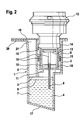
- the geometry of the housing 1 is so chosen that the probability of inclusion of an air bubble in the cartridge is minimized. This is u. a. an inclined bottom 17 (see Figures 2 and 3) of the holding chamber 5, in order to keep the air trapping small, when test liquid in the holding chamber 5 by a Opening 21 is filled.
- a measuring cell 8 can be used, to which a capillary tube 9 is attached.
- barrier ribs 18 for positioning a suction port 13 of a suction device 12 (see Figures 2 and 3) attached.
- four such barrier ribs 18th provided, of which two in Fig. 1 and two in Fig. 2 are shown.
- the measuring cell 8 has a peripheral upper edge 16.
- FIGS. 2 and 3 show sectional views along the line I-I of FIG. 1.
- FIG. 2 shows a first embodiment of the cartridge, in which the Capillary tube 9 projects into the interior of the measuring cell 8.
- the cartridge contains in the holding chamber 5, a liquid volume 7.
- the liquid volume 7 is through the filled test liquid 4 built.
- the holding chamber 5 is replaced by a separating element 2 completed at a height that is above the level of the test liquid 4 an air cushion 6 is located.
- FIG. 2 shows the configuration between the suction device 12 and the cartridge.
- the measuring cell 8 During the movement of the measuring cell 8 down the pierces Capillary tube 9, the separating element 2 and comes into contact with the test liquid 4 in the liquid volume 7 or immersed in this test liquid 4. In this position, the measuring cell 8 is generated by the suction device 12, a negative pressure in the measuring cell 8.
- the suction port 13 is equipped on its outside with an O-ring 14 on the edge 16 of the measuring cell 8 rests and contributes to the sealing of the measuring cell against the outside atmosphere.
- the test liquid 4 contains, for example, a mixture of glycerol and water and their Viscosity is adjusted to match the viscosity of normal blood. This amounts to the ratio of glycerol to water 30:70 to 40:60, based on the total weight of Mixture of glycerin and water. In particular, the ratio is glycerol to water 35:65 weight percent, each based on the total weight of the mixture of glycerol and Water.
- the initial flow rate of the test liquid 4 is determined by changing the length and the inner diameter of the capillary tube 9 controlled.
- the inner diameter of the capillary tube 9 is in the range of 100 to 220 microns, in particular it is 150 to 210 microns.
- the length of the capillary tube 9 is in the range of 15 to 30 mm. In a preferred embodiment. the inner diameter of the capillary tube is 200 ⁇ 10 ⁇ m and the length of the capillary tube 30 mm.
- the total volume of test fluid 4 is 300 to 400 ⁇ l, with a tolerance of ⁇ 5 to 7%.
- the capillary tube At a shortening the capillary tube at a constant inner diameter is the total volume of the Reduce test liquid to keep the flow rate constant.
- the size of the initial flow velocity, the total volume of test fluid, the volume of air or the air cushion 6 and the viscosity of the test liquid are chosen so that the standardized Shutter speed of 120 to 180 sec is maintained, which with the shutter speed of normal Blood matches. If it turns out during a measurement that the shutter speed of the Test fluid deviates from the standardized shutter speed, it can be assumed that the reviewed device for platelet diagnostics is not working properly works.
- the material for the capillary tube 9 is preferably stainless steel, wherein the predetermined maintained close tolerance for the inner diameter of a relatively smooth inner surface can be.
- the measuring cell 8 is expediently made of a plastic such as polypropylene or polyethylene terephthalate.
- FIG. 3 shows a further embodiment of the cartridge in section.
- This embodiment differs from the embodiment shown in Figure 2 only in that the capillary tube 9 is integrated with the measuring cell 8, in such a way that the capillary tube is integrally connected to the underside of the measuring cell 8 without protruding into the measuring cell.
- the top of the measuring cell 8 is closed except for a small opening 22.
- This opening 22 is connected to a suction port of the suction device 12.
- the capillary tube 9 has likewise pierced the separating element 2 and is in contact with the test liquid 4 of the liquid volume 7.
- the suction device 12 which rests sealingly on the measuring cell 8 via the O-ring 14, has the measuring cell 8 in the test chamber 3 pushed so far down that the measuring cell is seated on the base 11.
- the measuring cell 8 the barrier ribs can be omitted, since the measuring cell is closed on all sides except for the small opening 22.
- the test liquid 4 rises through the capillary tube 9 into the measuring cell and forms an increasing volume of liquid 10 until the negative pressure in the air cushion 6 above the liquid volume 7 equals the applied negative pressure in FIG the measuring cell 8 is.
- the single-use cartridge is discarded together with the test liquid 4 within the measuring cell 8 at the end of the test.
- the test liquid 4 is filled in the holding chamber 5, and then the holding chamber 5 is closed airtight with the separating element 2.
- a measuring cell 8 is introduced into the test chamber 3 and the test chamber by means of a sealing element 15, which on the inner wall of the housing 1 of the cartridge and an intermediate wall between the test chamber. 3 and the holding chamber 5 is applied, hermetically sealed. Thereafter, the top of the housing 1 is sealed airtight with a closure 19.
- the measuring cell 8 is located in a position next to the closure 19, wherein the capillary tube 9 connected to the measuring cell 8 is arranged with its lower end above the separating element 2, ie the separating element 2 is not pierced by the capillary tube 9.
- the closure 19 above the test chamber 3 is removed. As far as the shutter 19 covers the holding chamber 5, it remains.
- the capillary tube 9 connected to the measuring cell 8 is moved within the test chamber 3 in the direction of the separating element 2, caused by the pressure exerted by the suction device 12 mechanical pressure on the measuring cell 8, whereby these down to touchdown on the base 11th is pushed. During this movement, the capillary tube 9 pierces the separating element and comes into contact with the test liquid 4 of the liquid volume 7 or dips into the test liquid.
- a sufficient negative pressure in the measuring cell is generated, so that test liquid flows through the capillary tube 9 into the measuring cell and there is a liquid volume 10 is constructed. It measures the time it takes for the flow of test fluid to stop in the measuring cell. The beginning of the time measurement marks the application of the negative pressure to the measuring cell. The thus obtained shutter time is correlated with the time for blood flow in a predetermined normal range of the device for platelet diagnostics.
- Figure 4a shows a third embodiment of the cartridge, which is similar to the first embodiment is configured according to FIG.
- the sealing element 15 is formed in this embodiment as an O-ring.
- the capillary tube is surrounded by a sheath 23 within the holding chamber 5 and as far as the Capillary tube 9 projects into the measuring cell 8, it is from a further sheath 26th envelops.
- the capillary tube 9 is each surrounded by a sheath 23 or can be and that the first embodiment additionally has a sheath 26 or may have.
- the Capillary tube 9 passes through a separating element 25.
- a wall 27 between the holding chamber 5 and the test chamber 3 extends far down to close to the inclined bottom 17 and is bent or curved in the lower portion.
- the Separating element 25 is located between the wall and a wall of the housing 1 and closes the holding chamber 5 with respect to the test chamber 3.
- the test liquid is absorbed Liquid volume 7 within the holding chamber 5, wherein the liquid volume is about half the volume of the holding chamber 5 fills.
- a further separating element 24 which after the filling of the test liquid 4 in the holding chamber 5 is inserted at a distance from the flange 20. Between this separator 24 and the Level of the test liquid 4, the air cushion 6 is included.
- the remaining parts of the cartridge corresponding largely to the first embodiment according to Figure 2 and are the same Reference number as shown in Figure 2, so that they will not be described again.
- the fourth embodiment of Figure 4b is similar to the third embodiment of FIG 4a, so that only the different features to the third embodiment in Explained below.
- the opening 21 the holding chamber 5 closed after filling the test liquid with the separating element 24, which rests on the flange 20.
- the upper closure 19 of the cartridge vaulted the partition member 24 and terminates with the flange 20. After peeling off the closure 19 of the flange 20, the holding chamber 5 remains airtight by the separator 24 locked.
- the closure 19 consists for example of a self-adhesive film.
- the Air cushion 6 is larger in the fourth embodiment than in the third embodiment, since the partition member 24 is flush with the opening 21 of the holding chamber and not within the holding chamber, as in the third embodiment, is mounted.
- the capillary tube 9 penetrates the separating element 25.
- the configuration between the suction device and the cartridge is for the third and fourth Embodiment the same as described with reference to the first embodiment.
- the suction device is not shown in FIGS. 4a and 4b, however, that the negative pressure exerted by the suction device is the test liquid can flow through the capillary 9 in the measuring cell 8 and there the liquid volume 10 builds up until the negative pressure in the air cushion 6 above the liquid volume. 7 is equal to the applied negative pressure in the measuring cell 8.
- Flow rates of the test liquid can be normal as well as abnormal blood states simulates and thus the functional control of devices for blood platelet diagnostics with respect to abnormal blood compositions. This can be done by the Selection of the appropriate test liquid, in particular on its viscosity in Comparison with the viscosity of the sample to be tested in the cartridges according to the invention and other embodiments of the invention are achieved.
Landscapes
- Health & Medical Sciences (AREA)
- Life Sciences & Earth Sciences (AREA)
- Engineering & Computer Science (AREA)
- Chemical & Material Sciences (AREA)
- Hematology (AREA)
- Biomedical Technology (AREA)
- Physics & Mathematics (AREA)
- Immunology (AREA)
- Analytical Chemistry (AREA)
- General Health & Medical Sciences (AREA)
- Urology & Nephrology (AREA)
- Molecular Biology (AREA)
- Biochemistry (AREA)
- Food Science & Technology (AREA)
- Medicinal Chemistry (AREA)
- General Physics & Mathematics (AREA)
- Pathology (AREA)
- Microbiology (AREA)
- Cell Biology (AREA)
- Biotechnology (AREA)
- Clinical Laboratory Science (AREA)
- Chemical Kinetics & Catalysis (AREA)
- Ecology (AREA)
- Biophysics (AREA)
- Investigating Or Analysing Biological Materials (AREA)
Abstract
Description
| Messzelle der Vorrichtung | 3,8 % gepuffertes Citratblut Referenzbereich (s) | 3,2 % gepuffertes Citratblut Referenzbereich (s) |
| Collagen /Epinephrin | 94 - 193 | 82 - 150 |
| Collagen /ADP | 71 - 118 | 62 - 100 |
Ein besonders bevorzugtes erfindungsgemäßes Verfahren zur Funktionskontrolle einer Vorrichtung für die Untersuchung der Blutplättchenfunktion umfasst folgende Schritte:
- Figur 1
- in Explosionsdarstellung eine Kartusche zur Funktionskontrolle einer Vorrichtung für die Blutplättchendiagnostik nach der Erfindung;
- Figur 2
- eine Schnittdarstellung einer ersten Ausführungsform der Kartusche entlang der Linie I-I der Figur 1 in Kontakt mit einem Sauganschluss einer Saugvorrichtung;
- Figur 3
- eine Schnittdarstellung einer zweiten Ausführungsform der Kartusche entlang der Linie I-I der Figur 1 in Kontakt mit einem Sauganschluss einer Saugvorrichtung.
- Figuren 4a und 4b
- Schnittdarstellungen einer dritten und vierten Ausführungsform der Kartusche entlang der Linie I-I der Figur 1.
Die zur einmaligen Verwendung vorgesehene Kartusche wird zusammen mit der Testflüssigkeit 4 innerhalb der Messzelle 8 am Ende des Testes verworfen. Die in den Figuren 2 und 3 gezeigte Kartusche zur einmaligen Verwendung wird für den Test durch folgende Schritte vorbereitet. Zunächst wird die Testflüssigkeit 4 in die Haltekammer 5 eingefüllt und anschließend die Haltekammer 5 mit dem Trennelement 2 luftdicht abgeschlossen. Es befindet sich zwischen dem Trennelement 2 und dem Flüssigkeitsvolumen 7 ein Luftpolster 6. Als nächstes wird eine Messzelle 8 in die Testkammer 3 eingebracht und die Testkammer mittels eines Dichtungselements 15, das an der Innenwand des Gehäuses 1 der Kartusche und einer Zwischenwand zwischen der Testkammer 3 und der Haltekammer 5 anliegt, luftdicht abgeschlossen. Danach wird die Oberseite des Gehäuses 1 mit einem Verschluss 19 luftdicht verschlossen. Die Messzelle 8 befindet sich in einer Position nächst dem Verschluss 19, wobei das mit der Messzelle 8 verbundene Kapillarrohr 9 mit seinem unteren Ende oberhalb des Trennelements 2 angeordnet ist, d. h. das Trennelement 2 von dem Kapillarrohr 9 nicht durchstoßen ist. Als nächstes wird dann vor dem Einsetzen der Kartusche in die Vorrichtung für die Blutplättchendiagnostik der Verschluss 19 über der Testkammer 3 entfernt. Soweit der Verschluss 19 die Haltekammer 5 abdeckt, bleibt er erhalten. Im nächsten Schritt wird das mit der Messzelle 8 verbundene Kapillarrohr 9 innerhalb der Testkammer 3 in Richtung auf das Trennelement 2 bewegt, verursacht durch den von der Saugvorrichtung 12 ausgeübten mechanischen Druck auf die Messzelle 8, wodurch diese nach unten bis zum Aufsetzen auf den Sockel 11 geschoben wird. Bei dieser Bewegung durchstößt das Kapillarrohr 9 das Trennelement und gelangt mit der Testflüssigkeit 4 des Flüssigkeitsvolumens 7 in Kontakt bzw. taucht in die Testflüssigkeit ein. Durch die Saugvorrichtung 12 wird ein ausreichender Unterdruck in der Messzelle erzeugt, so dass Testflüssigkeit durch das Kapillarrohr 9 in die Messzelle fließt und dort ein Flüssigkeitsvolumen 10 aufgebaut wird. Es wird die Zeit gemessen, die benötigt wird, bis der Fluss der Testflüssigkeit in die Messzelle aufhört. Den Beginn der Zeitmessung markiert das Anlegen des Unterdrucks an die Messzelle. Die so erhaltene Verschlusszeit wird mit der Zeit für den Blutfluss in einem vorbestimmten Normalbereich der Vorrichtung für die Blutplättchendiagnostik korreliert.
Claims (31)
- Kartusche zur Funktionskontrolle einer Vorrichtung für die Untersuchung der Blutplättchenfunktion, mit einem Gehäuse (1), das eine Testkammer (3) und eine Haltekammer (5) umschließt, dadurch gekennzeichnet, dass ein Trennelement (2; 25) ein Flüssigkeitsvolumen (7) und ein darüber befindliches Luftpolster (6) in der Haltekammer (5) luftdicht abschließt, dass eine Messzelle (8) in den oberen Teil der Testkammer (3) einsetzbar ist und dass ein Kapillarrohr (9) die Messzelle mit dem Flüssigkeitsvolumen (7) verbindet.
- Kartusche nach Anspruch 1, dadurch gekennzeichnet, dass die Haltekammer (5) von einem oberen Verschluss (19) luftdicht abschließbar ist.
- Kartusche nach Anspruch 1 oder 2, dadurch gekennzeichnet, dass die Messzelle (8) auf einem umlaufenden Sockel (11) aufsitzt, der an der Innenwand der Testkammer (3) angebracht ist.
- Kartusche nach einem oder mehreren der Ansprüche 1 bis 3, dadurch gekennzeichnet, dass die Messzelle (8) zylindrisch ist und einen Durchmesser kleiner als der Innendurchmesser der Testkammer (3) aufweist.
- Kartusche nach einem oder mehreren der Ansprüche 1 bis 4, dadurch gekennzeichnet, dass ein Dichtungselement (15) zwischen der Außenseite der Messzelle (8) und der Innenwand der Testkammer (3) die Testkammer luftdicht gegen die Außenatmosphäre abschließt.
- Kartusche nach einem oder mehreren der Ansprüche 1 bis 5, dadurch gekennzeichnet, dass an die Messzelle (8) abdichtend eine Saugvorrichtung (12) anschließbar ist, die einen . Unterdruck in der Messzelle (8) erzeugt.
- Kartusche nach Anspruch 6, dadurch gekennzeichnet, dass die Saugvorrichtung (12) einen Sauganschluss (13) aufweist, der mit einem O-Ring (14) ausgerüstet ist.
- Kartusche nach Anspruch 7, dadurch gekennzeichnet, dass der O-Ring (14) dichtend auf einem Rand (16) der Messzelle (8) aufliegt.
- Kartusche nach einem öder mehreren der Ansprüche 1 bis 8, dadurch gekennzeichnet, dass das Kapillarrohr (9) mit seinem oberen Ende in die Messzelle (8) hineinragt, das Trennelement (2) durchsetzt und mit seinem unteren Ende in die Testflüssigkeit (4) des Flüssigkeitsvolumens (7) eintaucht.
- Kartusche nach einem oder mehreren der Ansprüche 1 bis 9, dadurch gekennzeichnet, dass die Messzelle (8) bis auf eine kleine Öffnung (22) in ihrer Oberseite und dem mit der Messzelle (8) verbundenen Kapillarrohr (9) allseitig geschlossen ist.
- Kartusche nach Anspruch 10, dadurch gekennzeichnet, dass das Kapillarrohr (9) integral mit 'der Unterseite der Messzelle (8) verbunden ist, ohne in die Messzelle (8) hineinzuragen.
- Kartusche nach einem oder mehreren der Ansprüche 1 bis 11, dadurch gekennzeichnet, dass die Testflüssigkeit (4) ein Gemisch aus Glycerin und Wasser enthält.
- Kartusche nach Anspruch 12, dadurch gekennzeichnet, dass das Verhältnis Glycerin zu Wasser 30:70 bis 40:60 Gewichtsprozent beträgt, bezogen auf das Gesamtgewicht der Mischung aus Glycerin und Wasser.
- Kartusche nach Anspruch 12, dadurch gekennzeichnet, dass das Verhältnis Glycerin zu Wasser 35:65 Gewichtsprozent beträgt, bezogen auf das Gesamtgewicht der Mischung aus Glycerin und Wasser.
- Kartusche nach einem oder mehreren der Ansprüche 1 bis 11, dadurch gekennzeichnet, dass die Testflüssigkeit Wasser, Öle, Polyethyenglycol und Mischungen hiervon enthält.
- Kartusche nach Anspruch 12 oder 15, dadurch gekennzeichnet, dass die Testflüssigkeit (4) Puffersubstanzen, Salze, antimikrobiell wirkende Substanzen, Nukleinsäureketten, Kohlehydratketten, Proteine enthält.
- Verfahren zur Funktionskontrolle einer Vorrichtung für die Untersuchung der Blutplättchenfunktion, das folgende Schritte umfasst:(1) Bereitstellen eines Flüssigkeitsvolumens (7) einer Testflüssigkeit (4) in einer Haltekammer (5);(2) luftdichtes Abschließen des Flüssigkeitsvolumens (7) und eines darüberbefindlichen Luftpolsters (6) mit einem Trennelement (2; 25);(3) luftdichtes Abschließen der Testkammer (3) mittels eines Dichtungselements (15) und Einbringen einer Messzelle (8) in die Testkammer;(4) Bewegen eines mit einer Messzelle (8) verbundenen Kapillarrohrs (9) innerhalb der Testkammer (3) in Richtung auf das Trennelement (2; 25) zu und Durchstoßen des Trennelements mit dem Kapillarrohr, so dass dieses mit der Testflüssigkeit in Kontakt gelangt bzw. in die Testflüssigkeit eintaucht;(5) Erzeugen eines ausreichenden Unterdrucks in der Messzelle, so dass Testflüssigkeit durch das Kapillarrohr hindurch in die Messzelle fließt;(6) Messen der Zeit, die benötigt wird, bis der Fluss der Testflüssigkeit in die Messzelle aufhört; und(7) Korrelieren der im Schritt (f) gemessenen Zeit mit einem vorbestimmten Referenzwert.
- Verfahren nach Anspruch 17, dadurch gekennzeichnet, dass die Viskosität der Test flüssigkeit gleich der Viskosität von Blut oder Blutplasma im Normalzustand gewählt wird.
- Verfahren nach Anspruch 17, dadurch gekennzeichnet, dass die Viskosität der Testflüssigkeit höher als die Viskosität von Blut oder Blutplasma im Normalzustand gewählt wird, so dass die Zeit gemäß Schritt(f) sich verlängert.
- Verfahren nach Anspruch 17, dadurch gekennzeichnet, dass die Viskosität der Testflüssigkeit niedriger als die Viskosität von Blut oder Blutplasma im Normalzustand gewählt wird, so dass die Zeit gemäß Schritt (f) sich verkürzt.
- Verfahren nach einem oder mehreren der Ansprüche 17 bis 20, dadurch gekennzeichnet, dass das Flüssigkeitsvolumen der Testflüssigkeit gegenüber dem Anfangszustand verringert wird, um die Zeit gemäß Schritt (f) zu verlängern.
- Verfahren nach einem oder mehreren der Ansprüche 17 bis 21, dadurch gekennzeichnet, dass das Kapillarrohr verlängert wird, um die Zeit gemäß Schritt (f) zu verlängern.
- Verfahren nach einem oder mehreren der Ansprüche 17 bis 22, dadurch gekennzeichnet, dass der Innendurchmesser des Kapillarrohrs verringert wird, um die Zeit gemäß Schritt (f) zu verlängern.
- Verwendung einer Testflüssigkeit zur Überprüfung und Kontrolle der technischen Funktionalität einer Messvorrichtung, welche über eine Messung des Drucks in einer Messkammer physiologische Prozesse wie z. B. die Gerinnungsfähigkeit einer Probe misst.
- Verwendung nach Anspruch 24, dadurch gekennzeichnet, dass es sich bei der Probe um Vollblut, Blutplasma oder plättchenreiches Blutplasma handelt.
- Verwendung nach Anspruch 24 oder 25, dadurch gekennzeichnet, dass die Viskosität der Testflüssigkeit vergleichbar, niedriger oder höher ist als die Viskosität der zu testenden Probe gewählt wird.
- Verwendung nach einem oder mehreren der Ansprüche 24 bis 26, dadurch gekennzeichnet, dass es sich bei der Testflüssigkeit um Wasser, Glycerin, Öle, Polyethylenglycol oder um ein Gemisch derselben handelt.
- Verwendung nach einem oder mehreren der Ansprüche 24 bis 27, dadurch gekennzeichnet, dass die Testflüssigkeit Puffersubstanzen, Salze, antimikrobiell wirkende Substanzen, Nukleinsäureketten, Kohlehydratketten, Proteine oder Gemische derselben enthält.
- Verwendung nach einem oder mehreren der Ansprüche 24 bis 28, dadurch gekennzeichnet, dass die Testflüssigkeit in einer Vorrichtung zur Blutplättchendiagnostik eingesetzt wird.
- Verwendung nach einem oder mehreren der Ansprüche 24 bis 29, dadurch gekennzeichnet, dass die Testflüssigkeit sich in einer Kartusche befindet.
- Verwendung nach Anspruch 30, dadurch gekennzeichnet, dass es sich um eine Kartusche gemäß einem oder mehreren der Ansprüche 1 bis 16 handelt.
Applications Claiming Priority (2)
| Application Number | Priority Date | Filing Date | Title |
|---|---|---|---|
| DE10360814 | 2003-12-23 | ||
| DE10360814A DE10360814A1 (de) | 2003-12-23 | 2003-12-23 | Kartusche zur Funktionskontrolle einer Vorrichtung für die Untersuchung der Blutplättchenfunktion, Verfahren zur Funktionskontrolle und Verwendung einer Testflüssigkeit |
Publications (3)
| Publication Number | Publication Date |
|---|---|
| EP1547689A2 true EP1547689A2 (de) | 2005-06-29 |
| EP1547689A3 EP1547689A3 (de) | 2005-08-03 |
| EP1547689B1 EP1547689B1 (de) | 2010-10-27 |
Family
ID=34530367
Family Applications (1)
| Application Number | Title | Priority Date | Filing Date |
|---|---|---|---|
| EP04027940A Expired - Lifetime EP1547689B1 (de) | 2003-12-23 | 2004-11-25 | Kartusche zur Funktionskontrolle einer Vorrichtung für die Untersuchung der Blutplättchenfunktion, Verfahren zur Funktionskontrolle und Verwendung einer Testflüssigkeit |
Country Status (7)
| Country | Link |
|---|---|
| US (1) | US7521247B2 (de) |
| EP (1) | EP1547689B1 (de) |
| JP (1) | JP4630053B2 (de) |
| AT (1) | ATE485887T1 (de) |
| CA (1) | CA2490432A1 (de) |
| DE (2) | DE10360814A1 (de) |
| ES (1) | ES2354977T3 (de) |
Families Citing this family (17)
| Publication number | Priority date | Publication date | Assignee | Title |
|---|---|---|---|---|
| US8448499B2 (en) | 2008-12-23 | 2013-05-28 | C A Casyso Ag | Cartridge device for a measuring system for measuring viscoelastic characteristics of a sample liquid, a corresponding measuring system, and a corresponding method |
| CA3028780C (en) * | 2009-12-07 | 2022-05-31 | Meso Scale Technologies, Llc | Assay cartridges and methods of using the same |
| US9625465B2 (en) | 2012-05-15 | 2017-04-18 | Defined Diagnostics, Llc | Clinical diagnostic systems |
| US9213043B2 (en) | 2012-05-15 | 2015-12-15 | Wellstat Diagnostics, Llc | Clinical diagnostic system including instrument and cartridge |
| US9075042B2 (en) | 2012-05-15 | 2015-07-07 | Wellstat Diagnostics, Llc | Diagnostic systems and cartridges |
| AU2014227711B2 (en) * | 2013-03-15 | 2020-04-09 | Haemonetics Corporation | Apparatus, cartridge and method for hemostasis testing |
| US10288630B2 (en) | 2014-09-29 | 2019-05-14 | C A Casyso Gmbh | Blood testing system and method |
| US10175225B2 (en) | 2014-09-29 | 2019-01-08 | C A Casyso Ag | Blood testing system and method |
| US10816559B2 (en) | 2014-09-29 | 2020-10-27 | Ca Casyso Ag | Blood testing system and method |
| US10539579B2 (en) | 2014-09-29 | 2020-01-21 | C A Casyso Gmbh | Blood testing system and method |
| US10473674B2 (en) | 2016-08-31 | 2019-11-12 | C A Casyso Gmbh | Controlled blood delivery to mixing chamber of a blood testing cartridge |
| US10843185B2 (en) | 2017-07-12 | 2020-11-24 | Ca Casyso Gmbh | Autoplatelet cartridge device |
| US10117615B1 (en) * | 2017-08-01 | 2018-11-06 | Nova Biomedical Corporation | Analyzer cartridge with capillary wiper |
| EP3830573B1 (de) * | 2018-07-29 | 2024-10-16 | KOC Universitesi | Instrument zur mikrofluidischen thromboelastometrie |
| KR102229025B1 (ko) * | 2019-07-19 | 2021-03-17 | 전북대학교산학협력단 | 소형 혈액점도측정 키트 및 그 카트리지 |
| CA3101865C (en) * | 2019-09-17 | 2023-10-17 | Nova Biomedical Corporation | Systems and methods for measuring liver enzyme levels in blood |
| CN111190000A (zh) * | 2020-03-02 | 2020-05-22 | 美高怡生生物技术(北京)有限公司 | 血小板功能判断方法及装置 |
Family Cites Families (12)
| Publication number | Priority date | Publication date | Assignee | Title |
|---|---|---|---|---|
| DE3247815C2 (de) | 1982-12-23 | 1985-10-17 | Gustav Viktor Rudolf Prof. London Born | Einrichtung zur Messung der Blutungszeit in vitro |
| DE3541057A1 (de) | 1985-11-19 | 1987-05-21 | Kratzer Michael | Verfahren und einrichtung zur messung der aggregation der blutplaettchen bzw. der koagulation des blutes |
| CA1294146C (en) * | 1986-05-30 | 1992-01-14 | Reuben E. Kron | Apparatus and method of measuring native mammalian blood viscosity |
| DE3739247C2 (de) * | 1987-11-19 | 1996-11-21 | Dade Int Inc | Blutungszeitmeßeinrichtung |
| ATE208493T1 (de) | 1994-06-30 | 2001-11-15 | Dade Behring Inc | Bioaktive poröse trennteile |
| US5888826A (en) * | 1994-06-30 | 1999-03-30 | Dade Behring Inc. | Combination reagent holding and test device |
| US5602037A (en) * | 1994-06-30 | 1997-02-11 | Dade International, Inc. | Combination reagent holding and test device |
| AU717559B2 (en) * | 1996-03-22 | 2000-03-30 | Dade Behring Inc. | Combination reagent holding and test device |
| US5925319A (en) * | 1996-04-30 | 1999-07-20 | Medtronic, Inc. | Test cartridge for evaluating blood platelet functionality |
| WO2002032224A1 (en) * | 2000-10-06 | 2002-04-25 | Dancu Michael B | System and method to simulate hemodynamics |
| US6746872B2 (en) * | 2002-01-16 | 2004-06-08 | Lifescan, Inc. | Control compositions and methods of use for coagulation tests |
| US7247488B2 (en) * | 2003-05-06 | 2007-07-24 | Medtronic, Inc. | Method and kit for testing a multi-channel blood assay cartridge |
-
2003
- 2003-12-23 DE DE10360814A patent/DE10360814A1/de not_active Withdrawn
-
2004
- 2004-11-25 AT AT04027940T patent/ATE485887T1/de not_active IP Right Cessation
- 2004-11-25 DE DE502004011818T patent/DE502004011818D1/de not_active Expired - Lifetime
- 2004-11-25 ES ES04027940T patent/ES2354977T3/es not_active Expired - Lifetime
- 2004-11-25 EP EP04027940A patent/EP1547689B1/de not_active Expired - Lifetime
- 2004-12-16 CA CA002490432A patent/CA2490432A1/en not_active Abandoned
- 2004-12-22 US US11/017,945 patent/US7521247B2/en not_active Expired - Fee Related
- 2004-12-22 JP JP2004370513A patent/JP4630053B2/ja not_active Expired - Fee Related
Also Published As
| Publication number | Publication date |
|---|---|
| ES2354977T3 (es) | 2011-03-21 |
| DE10360814A1 (de) | 2005-07-28 |
| EP1547689A3 (de) | 2005-08-03 |
| EP1547689B1 (de) | 2010-10-27 |
| CA2490432A1 (en) | 2005-06-23 |
| ATE485887T1 (de) | 2010-11-15 |
| JP2005181339A (ja) | 2005-07-07 |
| US20050136541A1 (en) | 2005-06-23 |
| US7521247B2 (en) | 2009-04-21 |
| DE502004011818D1 (de) | 2010-12-09 |
| JP4630053B2 (ja) | 2011-02-09 |
Similar Documents
| Publication | Publication Date | Title |
|---|---|---|
| EP1547689B1 (de) | Kartusche zur Funktionskontrolle einer Vorrichtung für die Untersuchung der Blutplättchenfunktion, Verfahren zur Funktionskontrolle und Verwendung einer Testflüssigkeit | |
| DE69524190T2 (de) | Kombinierte reagenzaufnahme und testanordnung | |
| DE69012195T2 (de) | Kapillare Durchflussvorrichtung und Verfahren zur Messung der aktivierten partiellen Thromboplastinzeit. | |
| EP1471353B1 (de) | Vorrichtung und Verfahren zur Erfassung von Gerinnungsfunktionen der globalen, insbesondere der primären Hämostase | |
| DE69523722T2 (de) | Bioaktive poröse trennteile | |
| EP2916950B1 (de) | Testset für eine photometrische messeinrichtung und photometrisches messverfahren für eine probenflüssigkeit | |
| DE60035199T2 (de) | Analysenkassette und flüssigkeitsförderkontroller | |
| DE69731439T2 (de) | Kombinierte reagenzaufnahme- und testanordnung | |
| DE60026933T2 (de) | Initiierung einer analytischen Messung in Blut | |
| EP1850135B1 (de) | Verfahren zur Bestimmung der Thrombozytenfunktion und der Flussbedingungen | |
| EP1850134B1 (de) | Verfahren und Vorrichtung zur Bestimmung der Thrombozytenfunktion und der Flussbedingungen | |
| EP0316599A2 (de) | Durchflussvorrichtung für die Verwendung in einer Blutungszeitmesseinrichtung und Verfahren zur Messung der Blutungszeit | |
| DE2701535A1 (de) | Verfahren und vorrichtung zur pharmakologischen beeinflussung des koagulationsmechanismus in koerperfluessigkeiten und zum anzeigen des eintritts der koagulation | |
| EP2500096B1 (de) | Vorrichtungen und verfahren zur bestimmung der plättchenfunktion in einem zentrifugalanalyzer | |
| DE69714568T2 (de) | Bestimmungsverfahren für einen Blutfaktor | |
| DE69919885T2 (de) | Verfahren zur messung der zellulären adhäsion | |
| CN215004989U (zh) | 一种微流体芯片及血小板功能检测装置 | |
| EP4384802A1 (de) | Verfahren zur erstellung einer datenbank zur ermittlung eines lichttransmissionsaggregometrie-referenzwerts und verfahren und vorrichtung zur durchführung einer lichttransmissionsaggregometrie-messung | |
| DE19543240A1 (de) | Einwegauftragsvorrichtung sowie Kit | |
| EP2274625B1 (de) | Vorrichtung und verfahren für die blutgerinnungsdiagnostik | |
| EP2543998B1 (de) | Verfahren zur Standardisierung von Messergebnissen in einem System zur Messung der Thrombozytenfunktion | |
| DE29521894U1 (de) | Einwegauftragsvorrichtung sowie Kit | |
| DE1806196A1 (de) | Verfahren zum Trennen einer Fluessigkeit in eine leichte und in eine schwere Phase und zur Abdichtung zwischen den getrennten Phasen sowie Anordnung zum Durchfuehren des Verfahrens | |
| Nemeh | Introduction fo" RTH-II" as a simple assay for screening PLT function specifically and reliably: validation, standardization and development of the procedures of the retention test of Homburg (RTH) in due of morphological control | |
| WO2000033073A2 (de) | Detektionsverfahren für no im vollblut von säugern |
Legal Events
| Date | Code | Title | Description |
|---|---|---|---|
| PUAI | Public reference made under article 153(3) epc to a published international application that has entered the european phase |
Free format text: ORIGINAL CODE: 0009012 |
|
| PUAL | Search report despatched |
Free format text: ORIGINAL CODE: 0009013 |
|
| AK | Designated contracting states |
Kind code of ref document: A2 Designated state(s): AT BE BG CH CY CZ DE DK EE ES FI FR GB GR HU IE IS IT LI LU MC NL PL PT RO SE SI SK TR |
|
| AX | Request for extension of the european patent |
Extension state: AL HR LT LV MK YU |
|
| AK | Designated contracting states |
Kind code of ref document: A3 Designated state(s): AT BE BG CH CY CZ DE DK EE ES FI FR GB GR HU IE IS IT LI LU MC NL PL PT RO SE SI SK TR |
|
| AX | Request for extension of the european patent |
Extension state: AL HR LT LV MK YU |
|
| 17P | Request for examination filed |
Effective date: 20060203 |
|
| AKX | Designation fees paid |
Designated state(s): AT BE BG CH CY CZ DE DK EE ES FI FR GB GR HU IE IS IT LI LU MC NL PL PT RO SE SI SK TR |
|
| 17Q | First examination report despatched |
Effective date: 20060725 |
|
| RAP1 | Party data changed (applicant data changed or rights of an application transferred) |
Owner name: SIEMENS HEALTHCARE DIAGNOSTICS PRODUCTS GMBH |
|
| GRAP | Despatch of communication of intention to grant a patent |
Free format text: ORIGINAL CODE: EPIDOSNIGR1 |
|
| GRAS | Grant fee paid |
Free format text: ORIGINAL CODE: EPIDOSNIGR3 |
|
| GRAA | (expected) grant |
Free format text: ORIGINAL CODE: 0009210 |
|
| AK | Designated contracting states |
Kind code of ref document: B1 Designated state(s): AT BE BG CH CY CZ DE DK EE ES FI FR GB GR HU IE IS IT LI LU MC NL PL PT RO SE SI SK TR |
|
| REG | Reference to a national code |
Ref country code: GB Ref legal event code: FG4D Free format text: NOT ENGLISH |
|
| REG | Reference to a national code |
Ref country code: CH Ref legal event code: NV Representative=s name: SIEMENS SCHWEIZ AG Ref country code: CH Ref legal event code: EP |
|
| REG | Reference to a national code |
Ref country code: IE Ref legal event code: FG4D Free format text: LANGUAGE OF EP DOCUMENT: GERMAN |
|
| REF | Corresponds to: |
Ref document number: 502004011818 Country of ref document: DE Date of ref document: 20101209 Kind code of ref document: P |
|
| REG | Reference to a national code |
Ref country code: NL Ref legal event code: VDEP Effective date: 20101027 |
|
| REG | Reference to a national code |
Ref country code: ES Ref legal event code: FG2A Effective date: 20110309 |
|
| REG | Reference to a national code |
Ref country code: IE Ref legal event code: FD4D |
|
| BERE | Be: lapsed |
Owner name: SIEMENS HEALTHCARE DIAGNOSTICS PRODUCTS G.M.B.H. Effective date: 20101130 |
|
| PG25 | Lapsed in a contracting state [announced via postgrant information from national office to epo] |
Ref country code: SE Free format text: LAPSE BECAUSE OF FAILURE TO SUBMIT A TRANSLATION OF THE DESCRIPTION OR TO PAY THE FEE WITHIN THE PRESCRIBED TIME-LIMIT Effective date: 20101027 Ref country code: NL Free format text: LAPSE BECAUSE OF FAILURE TO SUBMIT A TRANSLATION OF THE DESCRIPTION OR TO PAY THE FEE WITHIN THE PRESCRIBED TIME-LIMIT Effective date: 20101027 Ref country code: PT Free format text: LAPSE BECAUSE OF FAILURE TO SUBMIT A TRANSLATION OF THE DESCRIPTION OR TO PAY THE FEE WITHIN THE PRESCRIBED TIME-LIMIT Effective date: 20110228 Ref country code: BG Free format text: LAPSE BECAUSE OF FAILURE TO SUBMIT A TRANSLATION OF THE DESCRIPTION OR TO PAY THE FEE WITHIN THE PRESCRIBED TIME-LIMIT Effective date: 20110127 Ref country code: SI Free format text: LAPSE BECAUSE OF FAILURE TO SUBMIT A TRANSLATION OF THE DESCRIPTION OR TO PAY THE FEE WITHIN THE PRESCRIBED TIME-LIMIT Effective date: 20101027 Ref country code: IS Free format text: LAPSE BECAUSE OF FAILURE TO SUBMIT A TRANSLATION OF THE DESCRIPTION OR TO PAY THE FEE WITHIN THE PRESCRIBED TIME-LIMIT Effective date: 20110227 Ref country code: FI Free format text: LAPSE BECAUSE OF FAILURE TO SUBMIT A TRANSLATION OF THE DESCRIPTION OR TO PAY THE FEE WITHIN THE PRESCRIBED TIME-LIMIT Effective date: 20101027 |
|
| PG25 | Lapsed in a contracting state [announced via postgrant information from national office to epo] |
Ref country code: MC Free format text: LAPSE BECAUSE OF NON-PAYMENT OF DUE FEES Effective date: 20101130 Ref country code: GR Free format text: LAPSE BECAUSE OF FAILURE TO SUBMIT A TRANSLATION OF THE DESCRIPTION OR TO PAY THE FEE WITHIN THE PRESCRIBED TIME-LIMIT Effective date: 20110128 |
|
| PG25 | Lapsed in a contracting state [announced via postgrant information from national office to epo] |
Ref country code: IE Free format text: LAPSE BECAUSE OF FAILURE TO SUBMIT A TRANSLATION OF THE DESCRIPTION OR TO PAY THE FEE WITHIN THE PRESCRIBED TIME-LIMIT Effective date: 20101027 Ref country code: CZ Free format text: LAPSE BECAUSE OF FAILURE TO SUBMIT A TRANSLATION OF THE DESCRIPTION OR TO PAY THE FEE WITHIN THE PRESCRIBED TIME-LIMIT Effective date: 20101027 Ref country code: EE Free format text: LAPSE BECAUSE OF FAILURE TO SUBMIT A TRANSLATION OF THE DESCRIPTION OR TO PAY THE FEE WITHIN THE PRESCRIBED TIME-LIMIT Effective date: 20101027 |
|
| PG25 | Lapsed in a contracting state [announced via postgrant information from national office to epo] |
Ref country code: SK Free format text: LAPSE BECAUSE OF FAILURE TO SUBMIT A TRANSLATION OF THE DESCRIPTION OR TO PAY THE FEE WITHIN THE PRESCRIBED TIME-LIMIT Effective date: 20101027 Ref country code: PL Free format text: LAPSE BECAUSE OF FAILURE TO SUBMIT A TRANSLATION OF THE DESCRIPTION OR TO PAY THE FEE WITHIN THE PRESCRIBED TIME-LIMIT Effective date: 20101027 Ref country code: DK Free format text: LAPSE BECAUSE OF FAILURE TO SUBMIT A TRANSLATION OF THE DESCRIPTION OR TO PAY THE FEE WITHIN THE PRESCRIBED TIME-LIMIT Effective date: 20101027 Ref country code: BE Free format text: LAPSE BECAUSE OF NON-PAYMENT OF DUE FEES Effective date: 20101130 Ref country code: RO Free format text: LAPSE BECAUSE OF FAILURE TO SUBMIT A TRANSLATION OF THE DESCRIPTION OR TO PAY THE FEE WITHIN THE PRESCRIBED TIME-LIMIT Effective date: 20101027 |
|
| PLBE | No opposition filed within time limit |
Free format text: ORIGINAL CODE: 0009261 |
|
| STAA | Information on the status of an ep patent application or granted ep patent |
Free format text: STATUS: NO OPPOSITION FILED WITHIN TIME LIMIT |
|
| 26N | No opposition filed |
Effective date: 20110728 |
|
| REG | Reference to a national code |
Ref country code: DE Ref legal event code: R097 Ref document number: 502004011818 Country of ref document: DE Effective date: 20110728 |
|
| REG | Reference to a national code |
Ref country code: AT Ref legal event code: MM01 Ref document number: 485887 Country of ref document: AT Kind code of ref document: T Effective date: 20101125 |
|
| PG25 | Lapsed in a contracting state [announced via postgrant information from national office to epo] |
Ref country code: AT Free format text: LAPSE BECAUSE OF NON-PAYMENT OF DUE FEES Effective date: 20101125 |
|
| PG25 | Lapsed in a contracting state [announced via postgrant information from national office to epo] |
Ref country code: CY Free format text: LAPSE BECAUSE OF FAILURE TO SUBMIT A TRANSLATION OF THE DESCRIPTION OR TO PAY THE FEE WITHIN THE PRESCRIBED TIME-LIMIT Effective date: 20101027 |
|
| PG25 | Lapsed in a contracting state [announced via postgrant information from national office to epo] |
Ref country code: LU Free format text: LAPSE BECAUSE OF NON-PAYMENT OF DUE FEES Effective date: 20101125 Ref country code: HU Free format text: LAPSE BECAUSE OF FAILURE TO SUBMIT A TRANSLATION OF THE DESCRIPTION OR TO PAY THE FEE WITHIN THE PRESCRIBED TIME-LIMIT Effective date: 20110428 |
|
| PG25 | Lapsed in a contracting state [announced via postgrant information from national office to epo] |
Ref country code: TR Free format text: LAPSE BECAUSE OF FAILURE TO SUBMIT A TRANSLATION OF THE DESCRIPTION OR TO PAY THE FEE WITHIN THE PRESCRIBED TIME-LIMIT Effective date: 20101027 |
|
| REG | Reference to a national code |
Ref country code: FR Ref legal event code: PLFP Year of fee payment: 12 |
|
| PGFP | Annual fee paid to national office [announced via postgrant information from national office to epo] |
Ref country code: DE Payment date: 20160120 Year of fee payment: 12 Ref country code: CH Payment date: 20160202 Year of fee payment: 12 |
|
| REG | Reference to a national code |
Ref country code: FR Ref legal event code: PLFP Year of fee payment: 13 |
|
| PGFP | Annual fee paid to national office [announced via postgrant information from national office to epo] |
Ref country code: FR Payment date: 20161123 Year of fee payment: 13 Ref country code: GB Payment date: 20161114 Year of fee payment: 13 |
|
| PGFP | Annual fee paid to national office [announced via postgrant information from national office to epo] |
Ref country code: ES Payment date: 20161223 Year of fee payment: 13 Ref country code: IT Payment date: 20161128 Year of fee payment: 13 |
|
| REG | Reference to a national code |
Ref country code: DE Ref legal event code: R119 Ref document number: 502004011818 Country of ref document: DE |
|
| REG | Reference to a national code |
Ref country code: CH Ref legal event code: PL |
|
| PG25 | Lapsed in a contracting state [announced via postgrant information from national office to epo] |
Ref country code: LI Free format text: LAPSE BECAUSE OF NON-PAYMENT OF DUE FEES Effective date: 20161130 Ref country code: CH Free format text: LAPSE BECAUSE OF NON-PAYMENT OF DUE FEES Effective date: 20161130 |
|
| PG25 | Lapsed in a contracting state [announced via postgrant information from national office to epo] |
Ref country code: DE Free format text: LAPSE BECAUSE OF NON-PAYMENT OF DUE FEES Effective date: 20170601 |
|
| GBPC | Gb: european patent ceased through non-payment of renewal fee |
Effective date: 20171125 |
|
| REG | Reference to a national code |
Ref country code: FR Ref legal event code: ST Effective date: 20180731 |
|
| PG25 | Lapsed in a contracting state [announced via postgrant information from national office to epo] |
Ref country code: IT Free format text: LAPSE BECAUSE OF NON-PAYMENT OF DUE FEES Effective date: 20171125 Ref country code: FR Free format text: LAPSE BECAUSE OF NON-PAYMENT OF DUE FEES Effective date: 20171130 |
|
| PG25 | Lapsed in a contracting state [announced via postgrant information from national office to epo] |
Ref country code: GB Free format text: LAPSE BECAUSE OF NON-PAYMENT OF DUE FEES Effective date: 20171125 |
|
| REG | Reference to a national code |
Ref country code: ES Ref legal event code: FD2A Effective date: 20190103 |
|
| PG25 | Lapsed in a contracting state [announced via postgrant information from national office to epo] |
Ref country code: ES Free format text: LAPSE BECAUSE OF NON-PAYMENT OF DUE FEES Effective date: 20171126 |