EP1547666B1 - Rotor für Rotationsadsorber - Google Patents
Rotor für Rotationsadsorber Download PDFInfo
- Publication number
- EP1547666B1 EP1547666B1 EP05004118A EP05004118A EP1547666B1 EP 1547666 B1 EP1547666 B1 EP 1547666B1 EP 05004118 A EP05004118 A EP 05004118A EP 05004118 A EP05004118 A EP 05004118A EP 1547666 B1 EP1547666 B1 EP 1547666B1
- Authority
- EP
- European Patent Office
- Prior art keywords
- rotor
- end surface
- arc
- zone
- plate
- Prior art date
- Legal status (The legal status is an assumption and is not a legal conclusion. Google has not performed a legal analysis and makes no representation as to the accuracy of the status listed.)
- Expired - Lifetime
Links
Images




Classifications
-
- F—MECHANICAL ENGINEERING; LIGHTING; HEATING; WEAPONS; BLASTING
- F24—HEATING; RANGES; VENTILATING
- F24F—AIR-CONDITIONING; AIR-HUMIDIFICATION; VENTILATION; USE OF AIR CURRENTS FOR SCREENING
- F24F3/00—Air-conditioning systems in which conditioned primary air is supplied from one or more central stations to distributing units in the rooms or spaces where it may receive secondary treatment; Apparatus specially designed for such systems
- F24F3/12—Air-conditioning systems in which conditioned primary air is supplied from one or more central stations to distributing units in the rooms or spaces where it may receive secondary treatment; Apparatus specially designed for such systems characterised by the treatment of the air otherwise than by heating and cooling
- F24F3/14—Air-conditioning systems in which conditioned primary air is supplied from one or more central stations to distributing units in the rooms or spaces where it may receive secondary treatment; Apparatus specially designed for such systems characterised by the treatment of the air otherwise than by heating and cooling by humidification; by dehumidification
- F24F3/1411—Air-conditioning systems in which conditioned primary air is supplied from one or more central stations to distributing units in the rooms or spaces where it may receive secondary treatment; Apparatus specially designed for such systems characterised by the treatment of the air otherwise than by heating and cooling by humidification; by dehumidification by absorbing or adsorbing water, e.g. using an hygroscopic desiccant
- F24F3/1423—Air-conditioning systems in which conditioned primary air is supplied from one or more central stations to distributing units in the rooms or spaces where it may receive secondary treatment; Apparatus specially designed for such systems characterised by the treatment of the air otherwise than by heating and cooling by humidification; by dehumidification by absorbing or adsorbing water, e.g. using an hygroscopic desiccant with a moving bed of solid desiccants, e.g. a rotary wheel supporting solid desiccants
-
- B—PERFORMING OPERATIONS; TRANSPORTING
- B01—PHYSICAL OR CHEMICAL PROCESSES OR APPARATUS IN GENERAL
- B01D—SEPARATION
- B01D53/00—Separation of gases or vapours; Recovering vapours of volatile solvents from gases; Chemical or biological purification of waste gases, e.g. engine exhaust gases, smoke, fumes, flue gases, aerosols
- B01D53/02—Separation of gases or vapours; Recovering vapours of volatile solvents from gases; Chemical or biological purification of waste gases, e.g. engine exhaust gases, smoke, fumes, flue gases, aerosols by adsorption, e.g. preparative gas chromatography
- B01D53/06—Separation of gases or vapours; Recovering vapours of volatile solvents from gases; Chemical or biological purification of waste gases, e.g. engine exhaust gases, smoke, fumes, flue gases, aerosols by adsorption, e.g. preparative gas chromatography with moving adsorbents, e.g. rotating beds
-
- F—MECHANICAL ENGINEERING; LIGHTING; HEATING; WEAPONS; BLASTING
- F28—HEAT EXCHANGE IN GENERAL
- F28D—HEAT-EXCHANGE APPARATUS, NOT PROVIDED FOR IN ANOTHER SUBCLASS, IN WHICH THE HEAT-EXCHANGE MEDIA DO NOT COME INTO DIRECT CONTACT
- F28D19/00—Regenerative heat-exchange apparatus in which the intermediate heat-transfer medium or body is moved successively into contact with each heat-exchange medium
- F28D19/04—Regenerative heat-exchange apparatus in which the intermediate heat-transfer medium or body is moved successively into contact with each heat-exchange medium using rigid bodies, e.g. mounted on a movable carrier
- F28D19/041—Regenerative heat-exchange apparatus in which the intermediate heat-transfer medium or body is moved successively into contact with each heat-exchange medium using rigid bodies, e.g. mounted on a movable carrier with axial flow through the intermediate heat-transfer medium
- F28D19/042—Rotors; Assemblies of heat absorbing masses
- F28D19/044—Rotors; Assemblies of heat absorbing masses shaped in sector form, e.g. with baskets
-
- B—PERFORMING OPERATIONS; TRANSPORTING
- B01—PHYSICAL OR CHEMICAL PROCESSES OR APPARATUS IN GENERAL
- B01D—SEPARATION
- B01D2253/00—Adsorbents used in seperation treatment of gases and vapours
- B01D2253/10—Inorganic adsorbents
- B01D2253/106—Silica or silicates
- B01D2253/108—Zeolites
-
- B—PERFORMING OPERATIONS; TRANSPORTING
- B01—PHYSICAL OR CHEMICAL PROCESSES OR APPARATUS IN GENERAL
- B01D—SEPARATION
- B01D2253/00—Adsorbents used in seperation treatment of gases and vapours
- B01D2253/30—Physical properties of adsorbents
- B01D2253/34—Specific shapes
- B01D2253/342—Monoliths
- B01D2253/3425—Honeycomb shape
-
- B—PERFORMING OPERATIONS; TRANSPORTING
- B01—PHYSICAL OR CHEMICAL PROCESSES OR APPARATUS IN GENERAL
- B01D—SEPARATION
- B01D2257/00—Components to be removed
- B01D2257/70—Organic compounds not provided for in groups B01D2257/00 - B01D2257/602
- B01D2257/708—Volatile organic compounds V.O.C.'s
-
- B—PERFORMING OPERATIONS; TRANSPORTING
- B01—PHYSICAL OR CHEMICAL PROCESSES OR APPARATUS IN GENERAL
- B01D—SEPARATION
- B01D2258/00—Sources of waste gases
- B01D2258/02—Other waste gases
- B01D2258/0216—Other waste gases from CVD treatment or semi-conductor manufacturing
-
- B—PERFORMING OPERATIONS; TRANSPORTING
- B01—PHYSICAL OR CHEMICAL PROCESSES OR APPARATUS IN GENERAL
- B01D—SEPARATION
- B01D2259/00—Type of treatment
- B01D2259/40—Further details for adsorption processes and devices
- B01D2259/40083—Regeneration of adsorbents in processes other than pressure or temperature swing adsorption
- B01D2259/40088—Regeneration of adsorbents in processes other than pressure or temperature swing adsorption by heating
- B01D2259/4009—Regeneration of adsorbents in processes other than pressure or temperature swing adsorption by heating using hot gas
-
- F—MECHANICAL ENGINEERING; LIGHTING; HEATING; WEAPONS; BLASTING
- F24—HEATING; RANGES; VENTILATING
- F24F—AIR-CONDITIONING; AIR-HUMIDIFICATION; VENTILATION; USE OF AIR CURRENTS FOR SCREENING
- F24F2203/00—Devices or apparatus used for air treatment
- F24F2203/10—Rotary wheel
- F24F2203/1016—Rotary wheel combined with another type of cooling principle, e.g. compression cycle
-
- F—MECHANICAL ENGINEERING; LIGHTING; HEATING; WEAPONS; BLASTING
- F24—HEATING; RANGES; VENTILATING
- F24F—AIR-CONDITIONING; AIR-HUMIDIFICATION; VENTILATION; USE OF AIR CURRENTS FOR SCREENING
- F24F2203/00—Devices or apparatus used for air treatment
- F24F2203/10—Rotary wheel
- F24F2203/1032—Desiccant wheel
-
- F—MECHANICAL ENGINEERING; LIGHTING; HEATING; WEAPONS; BLASTING
- F24—HEATING; RANGES; VENTILATING
- F24F—AIR-CONDITIONING; AIR-HUMIDIFICATION; VENTILATION; USE OF AIR CURRENTS FOR SCREENING
- F24F2203/00—Devices or apparatus used for air treatment
- F24F2203/10—Rotary wheel
- F24F2203/1048—Geometric details
-
- F—MECHANICAL ENGINEERING; LIGHTING; HEATING; WEAPONS; BLASTING
- F24—HEATING; RANGES; VENTILATING
- F24F—AIR-CONDITIONING; AIR-HUMIDIFICATION; VENTILATION; USE OF AIR CURRENTS FOR SCREENING
- F24F2203/00—Devices or apparatus used for air treatment
- F24F2203/10—Rotary wheel
- F24F2203/1068—Rotary wheel comprising one rotor
-
- F—MECHANICAL ENGINEERING; LIGHTING; HEATING; WEAPONS; BLASTING
- F24—HEATING; RANGES; VENTILATING
- F24F—AIR-CONDITIONING; AIR-HUMIDIFICATION; VENTILATION; USE OF AIR CURRENTS FOR SCREENING
- F24F2203/00—Devices or apparatus used for air treatment
- F24F2203/10—Rotary wheel
- F24F2203/108—Rotary wheel comprising rotor parts shaped in sector form
-
- F—MECHANICAL ENGINEERING; LIGHTING; HEATING; WEAPONS; BLASTING
- F24—HEATING; RANGES; VENTILATING
- F24F—AIR-CONDITIONING; AIR-HUMIDIFICATION; VENTILATION; USE OF AIR CURRENTS FOR SCREENING
- F24F2203/00—Devices or apparatus used for air treatment
- F24F2203/10—Rotary wheel
- F24F2203/1084—Rotary wheel comprising two flow rotor segments
-
- F—MECHANICAL ENGINEERING; LIGHTING; HEATING; WEAPONS; BLASTING
- F24—HEATING; RANGES; VENTILATING
- F24F—AIR-CONDITIONING; AIR-HUMIDIFICATION; VENTILATION; USE OF AIR CURRENTS FOR SCREENING
- F24F2203/00—Devices or apparatus used for air treatment
- F24F2203/10—Rotary wheel
- F24F2203/1088—Rotary wheel comprising three flow rotor segments
-
- F—MECHANICAL ENGINEERING; LIGHTING; HEATING; WEAPONS; BLASTING
- F24—HEATING; RANGES; VENTILATING
- F24F—AIR-CONDITIONING; AIR-HUMIDIFICATION; VENTILATION; USE OF AIR CURRENTS FOR SCREENING
- F24F2203/00—Devices or apparatus used for air treatment
- F24F2203/10—Rotary wheel
- F24F2203/1096—Rotary wheel comprising sealing means
Definitions
- the present invention relates to a rotor for a rotary adsorber according to the preamble of independent claim 1.
- Fig. 11 is a perspective view showing a principal portion of the rotary adsorber having a rotor rotatably held therein
- Fig. 12 is a perspective view of the rotor
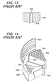
- Fig. 13 is a cross sectional view of Fig. 12 taken along the line A-A showing a seal-mating surfaces of each arc-shaped sector and the spoke
- Fig. 14 is a partially exploded perspective view showing the entire construction of the rotor including the outer peripheral rim 507.
- rotary adsorber 500 specifically for an organic solvent provided with a conventional adsorptive element 504
- adsorbed organic solvent has been removed by rotating the rotor 501 in the holding case 510 that is divided into an adsorbing zone S, a cooling zone T, and a recycling zone U, thereby temporarily defining a adsorbing zone and a recycling zone on one of the end surface of the rotor, adsorbing the organic solvent contained in gas onto the adsorbing element 504 carried by the rotor 501 when the surface of the rotor passes through the adsorbing zone S, and allowing recycling air heated to the temperature higher than 180°C-200°C, which is a boiling point of an organic solvent, to pass through the adsorptive element 504 from the end surface opposite from the end surface in the recycling zone U.
- a gas generated in the manufacturing process of semi-conductor components for example contains organic solvents such as DMSO (dimethyl sulfoxide) , MEA (monoethanol amine), HMDS (hexamethilenedisilazane), and so on.
- organic solvents such as DMSO (dimethyl sulfoxide) , MEA (monoethanol amine), HMDS (hexamethilenedisilazane), and so on.
- DMSO dimethyl sulfoxide
- MEA monoethanol amine
- HMDS hexamethilenedisilazane
- the rotor 501 of honeycomb construction integrally formed into a cylindrical shape by combining a plurality of arc-shaped sectors 502 is reinforced by a plurality of metallic spokes 503 extending radially outwardly from the hub 505.
- the metallic spoke and the sectors 502 of honeycomb construction are joined or bonded by the use of heat resistant calking material 508 such as silicone.
- the metallic outer peripheral rim 507 for protecting the outer periphery of the rotor 501 and the honeycomb construction 504 itself are also bonded via a calking material 508 of silicone.
- the rotor 501 is rotatably mounted to the holding case 510, and the partitioning plates 511 for defining the adsorbing zone S, the recycle zone U and the cooling zone T are provided with seal (not shown) formed of silicone rubber with PTFE film applied thereon so as to slidably press against the end surface of the rotor 501 to prevent leakage or mixing of gas passing therethrough.
- an organic solvent adsorber rotatably holds a rotor by a motor in a box-shaped casing having partitioning frame for dividing the surface of the rotor into an adsorbing zone, a recycling zone, and a cooling zone.
- the rotor includes an adsorptive element forming a plurality of fan-shaped sectors defined by a metallic cylindrical rim, which has a honeycomb construction in which a plurality of pores pass through from one end surface to the other end surface, and has the plurality of fan-shaped sectors inserted in fan-shaped spaces defined by radially extending metallic spokes.
- the partitioning frame defining these adsorbing zone and the recycling zone on the end surface of the rotor also includes at least three radially extending partitioning plates and an annular plate or an arc shaped plate facing toward the outer peripheral portion of the end surface of the rotor and defines each fan-shaped zone by being combined with the outer end portion of the partitioning plates.
- partitioning plates are further provided with sealing strips or resilient sealing blocks facing the end surface of the rotor so as to be slidable toward the end surface for preventing mutual interference of air in each fan-shared zone.
- Such kind of seal has a disadvantage in that it cannot establish complete sealing performance in the cases where flatness of the end surface of the rotor is not satisfactory as the first problem, and where the end surface of the rotor during rotation does not form a plane exactly perpendicular with respect to the axis of rotation as the second problem.
- DE 28 56 184 A refers to a rotor with separate sections, wherein the sections are separated from each other through profiles of a sealing frame. Heat can directly reach joint portions of the section and harm the same if the temperature rises over a predetermined value.
- the present invention shall provide a sealing device that can establish good sealing performance all the time while following the pits and projections on the surface of the rotor irrespective of the flatness or perpendicularity of the end surface of the rotor in order to overcome the problems described above.
- the rotor for a rotary adsorber comprises a cylindrical rim partitioned into a plurality of arc-shaped sectors by spokes radially disposed in the cylindrical rim, wherein each of the plurality of arc-shaped sectors including an element with a honeycomb construction; and an incombustible plate mounted on one end surface of the spoke covering adjacent ones of the plurality of arc-shaped sectors at a joint portion between the adjacent ones of the plurality of arc-shaped sectors.
- the rotor further comprises a recess formed between the adjacent ones of the plurality of arc-shaped sectors, wherein the incombustible plate is fitted into the recess.
- the incombustible plate comprises a laminated body including a thermal insulating seal and a metal plate overlaid on the thermal insulating seal.
- Fig. 1 is a perspective view of the rotor itself for rotary adsorber according to the present invention
- Fig. 2 is a partial cross sectional view of Fig. 1 taken along the line X-X illustrating an embodiment of the rotor for the rotary adsorber according to the present invention
- Fig. 3 is a same drawing as Fig. 2 showing another embodiment of the rotor for rotary adsorber according to the present invention
- Fig. 4 is a same drawing as Fig. 3 showing another embodiment of the rotor for rotary adsorber according to the present invention
- Fig. 1 is a perspective view of the rotor itself for rotary adsorber according to the present invention
- Fig. 2 is a partial cross sectional view of Fig. 1 taken along the line X-X illustrating an embodiment of the rotor for the rotary adsorber according to the present invention
- Fig. 3 is a same drawing as Fig. 2 showing another embodiment of the rotor for rotary adsorber according to the present
- FIG. 5 is a partially exploded perspective view showing the entire construction of a rotor for rotary adsorber according to the present invention including an outer peripheral rim provided with a thermal insulating seal; and Fig. 6 is a cross sectional view of Fig. 1 taken along the line Y-Y of a rotor for the rotary adsorber according to the present invention including outer peripheral rim provided with a thermal insulating seal.
- the thermal insulating seals 9 and 11 of the rotor 1 for rotary adsorbers according to the present invention is provided with eight arc-shaped sectors 2 each including a gas adsorptive element 4 of ceramic fiber paper of honeycomb construction having a number of through holes in the cylindrical rim 7 partitioned into arc-shaped portions in cross section by spokes 3 radially extending therein.
- the contact surface between adjacent two sectors 2 out of the sectors and the combination of the spoke 3 and rim 7 are integrally formed by silicone joined by a preferable calking material 8.
- the rotor including the gas adsorptive element 4 of honeycomb construction has a construction having a number of small through holes extending across both end surfaces, and especially when it is used for the process of cleaning a volatile organic compound containing gas generated in a semi-conductor manufacturing process, a harmful volatile organic compound contained in the gas is adsorbed on the surface of the small through holes when the gas is passed through the small through holes.
- Incombustible materials that can be used for the gas adsorptive element 4 of the rotor in the present invention are required to have heat resistance, heat-insulating property, wear resistance, and solvent resistant property.
- heat resistance when the temperature of the rotor increases, the portion between the spokes, which is supporting the rotor, and the honeycomb construction is deformed by high heat, and thus there is no other choice but to use incombustible materials in order to prevent such deformation.
- the reason why heat resistance is required is because the material has to resist air at a high temperature of 200-350°C
- the reason why heat insulating property is required is because the material have to protect the rotor from the air at a high temperature of 200-350°C.
- Wear resistance is required because friction is generated between itself and the sealing material described later, and solvent resistant property is required because the rotor has a property of adsorbing organic solvent.
- materials formed of inorganic material such as silicone nitride, graphite, ceramic paper, or felt are employable.
- Fig. 1 and Fig. 5 show a state in which the thermal insulating seals 10, 11 formed of plates of incombustible material for the rotor 1 of rotary adsorber are mounted on one end surface of the spoke 3 and the outer peripheral rim 7 of this rotor in parallel therewith, and according to an embodiment of the present invention, these thermal insulating seals are plates of incombustible material; silicone nitride.
- silicone nitride is preferable material.
- the construction of the present invention will be clearly understood from the description regarding the embodiment shown in Figs. 2 to 6 .
- Fig. 2 shows an embodiment of the rotor 1 for rotary adsorber according to the present invention showing the relation between the spoke 3 of the rotor 1 and silicone nitride plate 10 as a thermal insulating seal.
- the metallic spoke 3 is joined or adhered to the two adjacent sectors 2a, 2b out of six arc-shaped sectors constituting the rotor 1 with a calking material 8.
- the spoke 3 is provided with a metallic mounting plate 9 welded thereon at a right angle, in other words, in parallel with the end surface of the rotor 1, and the silicone nitride plate 10 is fixed to the mounting plate 9 by a screw 13.
- the silicone nitride plate 10 is wider than the mounting plate 9 exposed on the end surface of the rotor in width, and is as wide as it can be fitted into the radially extending rectangular recess 14 in cross section, which is formed at the joint portion between two adjacent sectors 2a, 2b with the spoke 3 interposed therebetween. Therefore, a preferable effect is obtained such that the thermal insulating seal does not project from the end surface of the rotor, so that the collision with the rotor-holding member that can be provided on the partitioning plate 511 of the holding case 510 can be avoided during service.
- heat insulating material 17 of, for example, calcium silicate plate between the mounting plate 9 of the spoke 3 and the silicone nitride plate 10 heat insulating performance can be further improved.
- Fig. 5 and Fig. 6 are cross sectional drawings of the end surface of the rotor, showing a state in which a silicone nitride plate 11 is mounted at the peripheral edge portion of the metallic outer peripheral rim 7 that appears on the end surface of the arc-shaped sector 2.
- the joint portion is protected from heat by protecting the calking material 8 by a silicone nitride plate 11.
- a metallic angle member 12 under the silicone nitride plate 11 so as to be embedded in the outer peripheral edge portion of the sector, it is also possible to provide the silicone nitrides plate 11 alone.
- the rotor 501 is stored in the case 510.
- the case 510 can rotatably accommodate the rotor 501, and divide the end surface of the rotor into the adsorbing zone S and the recycling zone U.
- the recycling zone U interposing the adsorbing zone S and the cooling zone T is divided by the partitioning plate 511 for defining each zone, and the partitioning plate 511 is provided with a sealing material so as to be able to come into contact with the end surface of the rotating rotor to prevent leakage of gas between zones.
- the rotor for rotary adsorber according to the present invention is constructed in such a manner that arc-shaped sectors formed of a gas adsorptive element of the honeycomb construction having a number of small through holes are arranged in the cylindrical rim partitioned into arc-shaped portions in cross section by the spoke radially extending therein, a calking material is interposed between these respective sectors and the combination of the spoke and rim, and a thermal insulating seal in the shape of a plate formed of incombustible material for covering an end surface of the spoke and the joint surface of the two arc-shaped sectors that come into contact with both sides of the end surface is mounted in parallel with the end surface, even when the high boiling organic solvent in excess of 200°C or a solvent that can be polymerized both of which were not able to be processed in the related art is attached to the adsorptive element, a hot air higher than 200 °C can be flown into the rotor continuously all the time at the recycle zone without causing deteriorati
- the rotor for rotary adsorbers according to the present invention enables removal of an organic solvent attached onto the adsorptive element, which has been impossible to be cleaned in the related art, and enables the adsorptive element in the rotor to be used continuously and repetitively without lowering the performance thereof and the mechanical strength of the rotor itself. Therefore, quick and smooth operation of exhaust gas processing can be performed continuously, and lowering of efficiency of exhaust gas processing can be prevented, thereby contributing to elongate the life of the rotor significantly.
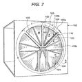
- Fig. 7 is a perspective view of the sealing device for rotary gas adsorbers according to the present invention in usual service condition in which the sealing device is accommodated in the case;
- Fig. 8 is a perspective view of the rotor being suitable for using the sealing device according to the present invention and having an end surface applied with a thermal insulating process by covering the joined portion between the combination of the spoke and rim and the fan-shaped sector formed of a adsorptive element with a plate body formed of incombustible material;
- Fig. 9 is a partial cross sectional view of the sealing device of Fig. 7 taken along the line A-A showing a state in which sealing devices according to the present invention are disposed along the radius of the end surface of the rotor;
- Fig. 10 is a partial cross-sectional view as Fig. 9 showing the sealing device of Fig. 7 according to the present invention taken along the line B-B, showing a state in which the sealing device is disposed circumferentially along the end surface of the rotor.
- the case 102 can rotatably accommodate the rotor 101, and here, the end surface of the rotor M is described only regarding the adsorption zone S and the recycling zone U thereof for the convenience of description.
- the angular range shown by the sign "T" is a cooling zone.
- the adsorption zone S and the recycling zone U are divided by the partitioning plates 103 integral with a case 102 for partitioning zones, and the partitioning plate 103 is provided with sealing material 104 to prevent leakage of gas between the respective zones on the end surface of the rotor.
- the linear partitioning plate 103 and the arc-shaped 103b for partitioning between the adsorbing zone and the recycling zone, between the cooling zone and the recycling zone, and between the peripheral portion of the rotor and the peripheral recycling zone is provided with a mounting plate 107 for the sealing material 105 fixed thereon with the nuts 110 ( Fig. 9 ) or a machine screws 113 ( Fig. 10 ).
- the sealing material 105 to be slid on the rotor 101 is secured to the connecting portion 108, which is fixed to the partitioning plate 103 with the nut 110 and a machine screw 113 in the state being bent at a right angle from the mounting plate 107, with the nut 110 via a rod member 109, and a spring 111 including a coil spring enclosing the rod member 109 is interposed between the connecting portion 108 and the sealing material 105, whereby the sealing material is urged toward the end surface of the rotor resiliently but still slidably by the use of a shock absorbing force and a restoring force of the spring.
- the sealing material 105 used here is required to have heat resistance, wear resistance, and chemical stability.
- Materials suitable for such sealing material will be preferably expanded black lead or graphite.
- materials suitable for the spring will be preferably general stainless or a material with a trade name of "Inconel” or the like.
- the conventional sealing device has a structure for directly mounting sealing material formed of band-shaped resilient body to the partitioning plate of the case, and thus a malfunction may occur in the rotor being provided with heat resistant thermal insulating seal along the edge of the spoke and the rim.
- Fig. 8 the rotor of the type described above will be described.
- the rotor 101 includes a spoke 203 (See Fig. 9 ) radially extending from a hub 205 and a rim 207 annularly surrounding the spoke portion, and a fan-shaped sector 202 including a adsorptive element 204. It has an end surface applied with a thermal insulation process by covering the respective joined portions 208 (See Fig. 9 and Fig. 10 ) between the combination of spoke and rim and the fan-shape sector with thermal insulating plates 210 and 211 formed of incombustible material. Referring to Fig. 9 and Fig. 10 , these thermal insulating plates 210 and 211 are flash with or a bit below the end surface M of the rotor 101.
- the sealing material 105 exhibits its sealing performance when being slid on the end surface M of the rotor
- the sealing material 105 according to the present invention is based on the precondition that it slides on the end surface M applied with a incombustible material as shown in Fig. 9 . Therefore, the sealing device of the present invention is constructed in such a manner that the sealing material 105 can follow the pits and projections on the end surface of the rotor with the aid of a resilient force and a restoring force of the spring 111 to ensure smooth sliding movement, thereby establishing a good sealing performance of each operating zone all the time.
- the structure of the sealing device shown in Fig. 10 is essentially the same as that shown in Fig. 9 .
- a method of mounting the sealing device is slightly changed so that it can slide on incombustible material having a good slipping property provided along the outer peripheral edge of the rotor 101, for example, an annular thermal insulating plate 211 formed of expanded black lead.
- the folded edge 103b of the outer peripheral edge 103a defining the operating area which is a circular cut-off portion of the surface plate of the case 102 serves substantially as a partitioning frame 103b, and the sealing material 105 is guided between the partitioning frame 103b and a mounting plate 107 extending in parallel thereto, and movably mounted to the rod member 109, which is secured to the connecting portion 108 with a screw, while undergoing a resilient force of the spring 111, which is a coil spring enclosing the rod member 109. Therefore, the sealing device shown in Fig. 10 is disposed only along the arc-shaped portion in the angular range of the recycling zone U of the case 102 in Fig. 7 . The reason why the sealing material 104 of the present invention is disposed only along the arc-shaped portion of the recycling zone U is that this region is exposed to a hot air in order to blow off an organic solvent adhered on the adsorptive element.
- the sealing material 105 is formed with a cylinder hole 114 in which an engaging portion formed on the tip of the rod member 109 is inserted.
- the engaging portion has a piston shape that can slidably fit substantially in the cylinder hole 114.
- the sealing material 105 includes a resilient sheet strip 115 inserted between the sealing material and either one or both of the partitioning frame 103 and the mounting plate 107 which hold the sealing material therebetween.
- Resiliently interposing the sealing material 105 in such a manner exhibits a shock absorbing action between the partitioning frame 103 and the mounting plate 107 so that the sealing material is not damaged by the impact applied when the sealing material passes over the pits and projection on the end surface of the rotor during the sliding movement thereon.
- the resilient sheet strip 115 is, as described above, formed of an expanded black lead according to an embodiment of the present invention. This material is quite preferable in increasing heat resistance and wear resistance as well as resiliency as a matter of course.
- the sealing device for rotary gas adsorbers has such a structure that the sealing material formed of incombustible material is interposed between the partitioning frame and the mounting plate extending from the partitioning frame in parallel thereto so as to be slidable toward the end surface of the rotor, that the mounting plate is fixed to the partitioning frame via the connecting portion, that the sealing material includes a cylinder hole formed therein and is movably held by a rod member having an engaging portion extending into the cylinder hole at the tip portion thereof and secured to the connecting portion with a screw at the rear end thereof, and that a spring enclosing the rod member is interposed between the sealing material and the connecting portion to resiliently urge the sealing material toward the end surface of the rotor, sealing performance between operating zones is significantly improved irrespective of the flatness and perpendicularity of the end surface of the rotor, and lowering of efficiency of the process of exhaust gas is prevented even though the structure is simple, thereby elongating the life of the rotor are obtained.
Landscapes
- Engineering & Computer Science (AREA)
- Chemical & Material Sciences (AREA)
- General Engineering & Computer Science (AREA)
- Mechanical Engineering (AREA)
- General Chemical & Material Sciences (AREA)
- Analytical Chemistry (AREA)
- Oil, Petroleum & Natural Gas (AREA)
- Chemical Kinetics & Catalysis (AREA)
- Combustion & Propulsion (AREA)
- Physics & Mathematics (AREA)
- Thermal Sciences (AREA)
- Separation Of Gases By Adsorption (AREA)
- Sealing Devices (AREA)
Claims (3)
- Rotor für einen Dreh-Absorber, der umfasst:eine zylindrische Felge (7), die durch Speichen (3), die radial in der zylindrischen Felge (7) angeordnet sind, in eine Vielzahl bogenförmiger Sektoren (2) unterteilt wird, dadurch gekennzeichnet, dass jeder der Vielzahl bogenförmiger Sektoren (2) ein Element (4) mit einer Wabenkonstruktion sowie eine nicht brennbare Platte (10) enthält, die an einer Endfläche der Speiche angebracht ist und benachbarte der Vielzahl bogenförmiger Sektoren (2) an einem Verbindungsabschnitt zwischen den benachbarten der Vielzahl bogenförmiger Sektoren (2) abdeckt.
- Rotor nach Anspruch 1, der des Weiteren eine Vertiefung (14) umfasst, die zwischen den benachbarten der Vielzahl bogenförmiger Sektoren (2) ausgebildet ist, wobei die nicht brennbare Platte (10) in die Vertiefung (14) eingepasst ist.
- Rotor nach Anspruch 1 oder 2, wobei die nicht brennbare Platte (10) einen laminierten Körper, der eine thermisch isolierende Dichtung enthält, sowie eine Metallplatte umfasst, die auf die thermisch isolierende Dichtung aufgelegt ist.
Applications Claiming Priority (5)
| Application Number | Priority Date | Filing Date | Title |
|---|---|---|---|
| JP2000094867A JP3570621B2 (ja) | 2000-03-30 | 2000-03-30 | 回転型ガス吸着機におけるシール装置 |
| JP2000094867 | 2000-03-30 | ||
| JP2000098392A JP3570622B2 (ja) | 2000-03-31 | 2000-03-31 | 回転型吸着機用ロータ |
| JP2000098392 | 2000-03-31 | ||
| EP01106131A EP1138368B1 (de) | 2000-03-30 | 2001-03-13 | Rotor für Rotationsadsorber |
Related Parent Applications (2)
| Application Number | Title | Priority Date | Filing Date |
|---|---|---|---|
| EP01106131A Division EP1138368B1 (de) | 2000-03-30 | 2001-03-13 | Rotor für Rotationsadsorber |
| EP01106131.4 Division | 2001-03-13 |
Publications (2)
| Publication Number | Publication Date |
|---|---|
| EP1547666A1 EP1547666A1 (de) | 2005-06-29 |
| EP1547666B1 true EP1547666B1 (de) | 2011-10-19 |
Family
ID=26588925
Family Applications (4)
| Application Number | Title | Priority Date | Filing Date |
|---|---|---|---|
| EP05004118A Expired - Lifetime EP1547666B1 (de) | 2000-03-30 | 2001-03-13 | Rotor für Rotationsadsorber |
| EP10011737A Withdrawn EP2302267A1 (de) | 2000-03-30 | 2001-03-13 | Dichtungsanordnung für Rotationsadsorber |
| EP03017766A Expired - Lifetime EP1369627B1 (de) | 2000-03-30 | 2001-03-13 | Dichtungsanordnung für Rotationsadsorber |
| EP01106131A Expired - Lifetime EP1138368B1 (de) | 2000-03-30 | 2001-03-13 | Rotor für Rotationsadsorber |
Family Applications After (3)
| Application Number | Title | Priority Date | Filing Date |
|---|---|---|---|
| EP10011737A Withdrawn EP2302267A1 (de) | 2000-03-30 | 2001-03-13 | Dichtungsanordnung für Rotationsadsorber |
| EP03017766A Expired - Lifetime EP1369627B1 (de) | 2000-03-30 | 2001-03-13 | Dichtungsanordnung für Rotationsadsorber |
| EP01106131A Expired - Lifetime EP1138368B1 (de) | 2000-03-30 | 2001-03-13 | Rotor für Rotationsadsorber |
Country Status (5)
| Country | Link |
|---|---|
| US (1) | US6527837B2 (de) |
| EP (4) | EP1547666B1 (de) |
| KR (1) | KR100409253B1 (de) |
| DE (1) | DE60111296T2 (de) |
| TW (1) | TW536422B (de) |
Families Citing this family (46)
| Publication number | Priority date | Publication date | Assignee | Title |
|---|---|---|---|---|
| EP1547666B1 (de) * | 2000-03-30 | 2011-10-19 | Nichias Corporation | Rotor für Rotationsadsorber |
| US6780227B2 (en) * | 2000-10-13 | 2004-08-24 | Emprise Technology Associates Corp. | Method of species exchange and an apparatus therefore |
| US6852141B2 (en) * | 2001-06-06 | 2005-02-08 | Donaldson Company, Inc. | Filter element having center piece and methods |
| JP3482409B1 (ja) * | 2002-05-30 | 2003-12-22 | 東京エレクトロン株式会社 | 減湿装置及び減湿方法 |
| DE10311914B4 (de) * | 2003-03-07 | 2005-02-17 | Hovalwerk Ag | Rotationswärmeaustauscher für raumlufttechnische Anlagen |
| US7166149B2 (en) * | 2004-01-12 | 2007-01-23 | Uop Llc | Adsorption process for continuous purification of high value gas feeds |
| CN100529278C (zh) | 2004-05-26 | 2009-08-19 | 株式会社康友 | 从空气中提取水的方法及实施该方法的装置 |
| JP2006068582A (ja) * | 2004-08-31 | 2006-03-16 | Seibu Giken Co Ltd | 回転式ガス吸着濃縮装置 |
| US7294178B2 (en) * | 2004-11-08 | 2007-11-13 | Visteon Global Technologies, Inc. | Low loss hydrocarbon (HC) adsorber device for air induction system |
| TW200801405A (en) * | 2006-06-23 | 2008-01-01 | Ind Tech Res Inst | Dehumidifying wheel replacing device of rotary dehumidifier |
| US7753995B2 (en) * | 2007-12-11 | 2010-07-13 | Seibu Giken Co., Ltd. | Gas concentrator |
| US8641809B2 (en) * | 2010-10-26 | 2014-02-04 | Munters Corporation | Rotor support system |
| DE112011104580B4 (de) | 2010-12-22 | 2023-07-06 | Eaton Intelligent Power Limited | Filteranordnung und verfahren zum regulieren von luft durch eine filteranordnung |
| US8821622B2 (en) | 2010-12-22 | 2014-09-02 | Cooper Technologies Company | Pre-filtration and maintenance sensing for explosion-proof enclosures |
| KR101170389B1 (ko) | 2011-03-22 | 2012-08-01 | (주)득영 | 로터리식 제습 장치 |
| CN103518067A (zh) * | 2011-04-29 | 2014-01-15 | 戴克斯威特美国有限公司 | 风扇过滤器装置 |
| JP5826627B2 (ja) * | 2011-12-27 | 2015-12-02 | 株式会社西部技研 | 吸着ロータ |
| JP2013202504A (ja) * | 2012-03-28 | 2013-10-07 | Mitsubishi Plastics Inc | ハニカム状吸着素子、その使用方法及びデシカント空調装置 |
| US10799828B2 (en) * | 2014-02-04 | 2020-10-13 | Carrier Corporation | Hard interface dynamic seals |
| JP6276083B2 (ja) * | 2014-03-26 | 2018-02-07 | 株式会社西部技研 | 回転式ガス吸着濃縮装置 |
| DE102015107476A1 (de) * | 2015-05-12 | 2016-11-17 | Elringklinger Ag | Wärmetauscherelemente, insbesondere für Rauchgasreinigungsanlagen von Kraftwerken |
| CN107202463A (zh) * | 2016-03-18 | 2017-09-26 | 青岛海尔智能技术研发有限公司 | 转轮式干燥器和制冷设备及制冷设备的控制方法 |
| JP6980686B2 (ja) | 2016-03-31 | 2021-12-15 | スヴァンテ インコーポレイテッド | 低熱導電率吸着ガス分離器 |
| US10295272B2 (en) * | 2016-04-05 | 2019-05-21 | Arvos Ljungstrom Llc | Rotary pre-heater for high temperature operation |
| US11027233B2 (en) * | 2016-08-17 | 2021-06-08 | Nichias Corporation | Absorption rotor, rotor element, method of manufacturing absorption rotor, and method of manufacturing rotor element |
| TWI624297B (zh) | 2016-11-22 | 2018-05-21 | 傑智環境科技股份有限公司 | 具有較佳結構強度的轉輪結構及包括該轉輪結構的流體處理設備 |
| TWI683696B (zh) * | 2016-11-22 | 2020-02-01 | 傑智環境科技股份有限公司 | 具有較佳結構強度的轉輪結構及包括該轉輪結構的流體處理設備 |
| CN108096990B (zh) * | 2016-11-25 | 2021-05-04 | 中国石油化工股份有限公司 | 一种吸附分离装置 |
| KR101840667B1 (ko) * | 2017-02-17 | 2018-03-21 | 조명현 | 유기화합물 농축처리장치 |
| US20190120566A1 (en) * | 2017-04-05 | 2019-04-25 | Arvos Ljungstrom Llc | A rotary pre-heater for high temperature operation |
| CN108120006A (zh) * | 2017-12-15 | 2018-06-05 | 安徽喜尔奇日用品有限公司 | 一种净化效率高的空气净化器 |
| KR102135090B1 (ko) * | 2018-02-23 | 2020-07-17 | 엘지전자 주식회사 | 휘발성 유기화합물 제거장치 |
| CN110871014A (zh) * | 2018-08-30 | 2020-03-10 | 开利公司 | 具有移动床结构的co2洗涤器 |
| CN109826955B (zh) * | 2019-02-26 | 2020-06-16 | 维珂瑞(北京)环境科技有限公司 | 一种废气浓缩装置的密封系统 |
| CN111375249B (zh) * | 2020-04-22 | 2021-11-30 | 邳州市景鹏创业投资有限公司 | 一种应用于贝壳类加工的空气净化装置 |
| CN116348412A (zh) * | 2020-06-09 | 2023-06-27 | 全球温控营运有限责任公司 | 连续运动直接空气捕集系统 |
| CN112728085B (zh) * | 2020-12-28 | 2021-10-15 | 中科新天地(合肥)环保科技有限公司 | 一种用于转轮气室的密封结构 |
| US20240302103A1 (en) * | 2021-03-26 | 2024-09-12 | Jan Kleindienst | Fixing device for reinforcing the joint of a rotary heat exchanger |
| WO2023175464A1 (en) * | 2022-03-18 | 2023-09-21 | Svante Inc. | Scalable multi-selector valve and seal system |
| JP2025518138A (ja) | 2022-05-27 | 2025-06-12 | ゼロ カーボン システムズ インコーポレイテッド | ハイスループット可動パネル直接空気回収システム |
| EP4360741A1 (de) * | 2022-10-24 | 2024-05-01 | Siemens Energy Global GmbH & Co. KG | System zur direkten lufterfassung von kohlendioxid |
| US20240216852A1 (en) * | 2022-12-28 | 2024-07-04 | Munters Corporation | Sealing device for a gas sorption rotor of an air treatment system and a gas sorption rotor arrangement for an air treatment system |
| CN117167478B (zh) * | 2023-08-02 | 2025-10-14 | 四川佳世特橡胶有限公司 | 一种耐高温且具有隔热功能的橡胶密封件 |
| DE102023124706A1 (de) * | 2023-09-13 | 2025-03-13 | Volkswagen Aktiengesellschaft | Anlage und Verfahren zum Abtrennen von Kohlenstoffdioxid aus der Umgebungsluft |
| CN118757799B (zh) * | 2024-06-24 | 2025-08-15 | 华能(浙江)能源开发有限公司玉环分公司 | 一种空预器轴向密封装置 |
| CN121401807B (zh) * | 2025-12-26 | 2026-04-14 | 山东和发环保科技有限公司 | 一种沸石分子筛吸附脱附VOCs废气的处理装置及处理方法 |
Citations (3)
| Publication number | Priority date | Publication date | Assignee | Title |
|---|---|---|---|---|
| US4296937A (en) * | 1978-07-20 | 1981-10-27 | Nissan Motor Company, Limited | Rubbing-contact sealing structure for rotary heat regenerator |
| JPH0290922A (ja) * | 1988-09-26 | 1990-03-30 | Kobe Steel Ltd | フロン含有ガス濃縮装置 |
| EP0495608A2 (de) * | 1991-01-14 | 1992-07-22 | Ngk Insulators, Ltd. | Dichtung für einen rotierenden Gaserhitzer |
Family Cites Families (24)
| Publication number | Priority date | Publication date | Assignee | Title |
|---|---|---|---|---|
| US2053159A (en) * | 1932-02-16 | 1936-09-01 | Davison Chemical Corp | Adsorber and system |
| US3183649A (en) | 1961-08-29 | 1965-05-18 | Mass Transfer Inc | Stepwise rotary adsorber including inflatable seal |
| SE332052B (de) * | 1967-07-20 | 1971-01-25 | Munters C | |
| US3789916A (en) * | 1971-04-06 | 1974-02-05 | Munters Ab Carl | Rotor for exchangers of the thermodynamic characteristics of two gas currents |
| DE2856184A1 (de) * | 1978-12-27 | 1980-07-03 | Kraftanlagen Ag | Umlaufender stofftauscher und verfahren zum stofftausch zwischen zwei gasstroemen |
| JPS56155614A (en) * | 1980-05-06 | 1981-12-01 | Mitsubishi Heavy Ind Ltd | Sealing device for desorption zone in gas treatment device |
| JPS56163720A (en) * | 1980-05-23 | 1981-12-16 | Mitsubishi Heavy Ind Ltd | Sealing device for desorption zone of gas treating equipment |
| US4452612A (en) * | 1982-09-22 | 1984-06-05 | Cubemco, Inc. | Separation and purification of gases and vapors by continuous pressure-swing adsorption |
| US5282975A (en) * | 1989-12-25 | 1994-02-01 | Technion Research And Development Foundation Ltd. | Removal of oil from water |
| JPH0523526A (ja) * | 1991-07-19 | 1993-02-02 | Mitsubishi Heavy Ind Ltd | 回転式ガス回収装置 |
| JPH05157004A (ja) * | 1991-12-04 | 1993-06-22 | Isuzu Motors Ltd | ピストンクラウン |
| JPH0681406A (ja) * | 1992-09-01 | 1994-03-22 | Sun A Chem Ind Co Ltd | 断熱構造体 |
| DE69425014T2 (de) * | 1993-04-21 | 2001-03-08 | Babcock-Hitachi K.K., Tokio/Tokyo | Kontakthülse zum Schweissen und Herstellungsverfahren dafür |
| US5572799A (en) * | 1994-07-22 | 1996-11-12 | Sanyo Electric Co., Ltd. | Ventilator/dryer assembly for adsorbing wet air in a room |
| US5595238A (en) | 1994-09-16 | 1997-01-21 | Engelhard/Icc | Rotatably supported regenerative fluid treatment wheel assemblies |
| JP3364033B2 (ja) * | 1995-01-30 | 2003-01-08 | 三菱重工業株式会社 | 回転式ガス分離装置 |
| JPH08219291A (ja) * | 1995-02-10 | 1996-08-27 | Nichias Corp | 金属被覆型ガスケット |
| US5628819A (en) | 1995-09-28 | 1997-05-13 | Calgon Carbon Corporation | Method and apparatus for continuous adsorption of adsorbable contaminates and adsorber regeneration |
| CA2316827C (en) * | 1998-01-06 | 2005-11-08 | Donald F. Steele | Rotary heat exchange wheel |
| US6004384A (en) * | 1998-06-03 | 1999-12-21 | Bry-Air, Inc. | Rotary adsorption apparatus |
| JP2000018388A (ja) * | 1998-07-01 | 2000-01-18 | Ishino Gasket Kogyo Kk | メタルガスケット |
| JP3803799B2 (ja) * | 1998-09-22 | 2006-08-02 | 株式会社西部技研 | ガス吸着濃縮装置 |
| JP2001077570A (ja) * | 1999-09-06 | 2001-03-23 | Fujitsu Ltd | ロータ型除湿機およびロータ型除湿機の始動方法ならびに電子機器への取付け構造 |
| EP1547666B1 (de) * | 2000-03-30 | 2011-10-19 | Nichias Corporation | Rotor für Rotationsadsorber |
-
2001
- 2001-03-13 EP EP05004118A patent/EP1547666B1/de not_active Expired - Lifetime
- 2001-03-13 EP EP10011737A patent/EP2302267A1/de not_active Withdrawn
- 2001-03-13 DE DE60111296T patent/DE60111296T2/de not_active Expired - Lifetime
- 2001-03-13 EP EP03017766A patent/EP1369627B1/de not_active Expired - Lifetime
- 2001-03-13 EP EP01106131A patent/EP1138368B1/de not_active Expired - Lifetime
- 2001-03-13 US US09/804,301 patent/US6527837B2/en not_active Expired - Lifetime
- 2001-03-13 TW TW090105849A patent/TW536422B/zh not_active IP Right Cessation
- 2001-03-13 KR KR10-2001-0012955A patent/KR100409253B1/ko not_active Expired - Lifetime
Patent Citations (3)
| Publication number | Priority date | Publication date | Assignee | Title |
|---|---|---|---|---|
| US4296937A (en) * | 1978-07-20 | 1981-10-27 | Nissan Motor Company, Limited | Rubbing-contact sealing structure for rotary heat regenerator |
| JPH0290922A (ja) * | 1988-09-26 | 1990-03-30 | Kobe Steel Ltd | フロン含有ガス濃縮装置 |
| EP0495608A2 (de) * | 1991-01-14 | 1992-07-22 | Ngk Insulators, Ltd. | Dichtung für einen rotierenden Gaserhitzer |
Also Published As
| Publication number | Publication date |
|---|---|
| DE60111296D1 (de) | 2005-07-14 |
| EP1138368A3 (de) | 2002-07-24 |
| KR100409253B1 (ko) | 2003-12-18 |
| KR20010094971A (ko) | 2001-11-03 |
| EP1369627B1 (de) | 2013-03-13 |
| EP1138368A2 (de) | 2001-10-04 |
| EP1369627A1 (de) | 2003-12-10 |
| EP1547666A1 (de) | 2005-06-29 |
| TW536422B (en) | 2003-06-11 |
| EP2302267A1 (de) | 2011-03-30 |
| EP1138368B1 (de) | 2005-06-08 |
| US6527837B2 (en) | 2003-03-04 |
| US20010026110A1 (en) | 2001-10-04 |
| DE60111296T2 (de) | 2005-11-10 |
Similar Documents
| Publication | Publication Date | Title |
|---|---|---|
| EP1547666B1 (de) | Rotor für Rotationsadsorber | |
| US4961588A (en) | Radial seal | |
| EP1508359B1 (de) | Entfeuchtungssystem und entfeuchtungsverfahren | |
| JP4085083B2 (ja) | 内側エアシール回転防止装置 | |
| US4929298A (en) | Tire building drum including an expandable segmental cylinder assembly and a vacuum chamber | |
| JP3570622B2 (ja) | 回転型吸着機用ロータ | |
| JP3570621B2 (ja) | 回転型ガス吸着機におけるシール装置 | |
| KR20150111838A (ko) | 회전식 가스 흡착 농축 장치 | |
| JP3674867B2 (ja) | 回転型吸着機用ロータ | |
| JP3653091B2 (ja) | 回転型吸着機用ロータ | |
| JP3601007B2 (ja) | 回転型ガス吸着機におけるシール装置及びシール方法 | |
| JP2009202081A (ja) | 回転式ガス処理装置のシール構造体及びシール方法 | |
| JP2004025132A (ja) | 吸着ローター | |
| JPH0116508Y2 (de) | ||
| CN120530286A (zh) | 用于空气处理系统的气体吸附转轮的密封装置和用于空气处理系统的气体吸附转轮布置结构 | |
| GB2087038A (en) | Mounting device for heat recovery wheels | |
| JPH01297283A (ja) | サーマルプリンタ | |
| WO2023203888A1 (ja) | 吸着ロータ及びその収納装置 | |
| KR20230019125A (ko) | 흡착 유닛, 흡착 처리 장치, 및 처리 시스템 |
Legal Events
| Date | Code | Title | Description |
|---|---|---|---|
| PUAI | Public reference made under article 153(3) epc to a published international application that has entered the european phase |
Free format text: ORIGINAL CODE: 0009012 |
|
| AC | Divisional application: reference to earlier application |
Ref document number: 1138368 Country of ref document: EP Kind code of ref document: P |
|
| AK | Designated contracting states |
Kind code of ref document: A1 Designated state(s): DE GB IT |
|
| 17P | Request for examination filed |
Effective date: 20050728 |
|
| RIN1 | Information on inventor provided before grant (corrected) |
Inventor name: TANAKA, YASUHIRONICHIAS CORPORATION Inventor name: ASAHINA, SHUSAKU Inventor name: KUROSAWA, MASAJI Inventor name: YAMASHITA, KATSUHIRO |
|
| AKX | Designation fees paid |
Designated state(s): DE GB IT |
|
| 17Q | First examination report despatched |
Effective date: 20080328 |
|
| GRAP | Despatch of communication of intention to grant a patent |
Free format text: ORIGINAL CODE: EPIDOSNIGR1 |
|
| GRAS | Grant fee paid |
Free format text: ORIGINAL CODE: EPIDOSNIGR3 |
|
| GRAA | (expected) grant |
Free format text: ORIGINAL CODE: 0009210 |
|
| AC | Divisional application: reference to earlier application |
Ref document number: 1138368 Country of ref document: EP Kind code of ref document: P |
|
| AK | Designated contracting states |
Kind code of ref document: B1 Designated state(s): DE GB IT |
|
| REG | Reference to a national code |
Ref country code: GB Ref legal event code: FG4D |
|
| REG | Reference to a national code |
Ref country code: DE Ref legal event code: R096 Ref document number: 60145554 Country of ref document: DE Effective date: 20111208 |
|
| PLBE | No opposition filed within time limit |
Free format text: ORIGINAL CODE: 0009261 |
|
| STAA | Information on the status of an ep patent application or granted ep patent |
Free format text: STATUS: NO OPPOSITION FILED WITHIN TIME LIMIT |
|
| 26N | No opposition filed |
Effective date: 20120720 |
|
| REG | Reference to a national code |
Ref country code: DE Ref legal event code: R097 Ref document number: 60145554 Country of ref document: DE Effective date: 20120720 |
|
| PGFP | Annual fee paid to national office [announced via postgrant information from national office to epo] |
Ref country code: GB Payment date: 20200304 Year of fee payment: 20 Ref country code: IT Payment date: 20200221 Year of fee payment: 20 Ref country code: DE Payment date: 20200303 Year of fee payment: 20 |
|
| REG | Reference to a national code |
Ref country code: DE Ref legal event code: R071 Ref document number: 60145554 Country of ref document: DE |
|
| REG | Reference to a national code |
Ref country code: GB Ref legal event code: PE20 Expiry date: 20210312 |
|
| PG25 | Lapsed in a contracting state [announced via postgrant information from national office to epo] |
Ref country code: GB Free format text: LAPSE BECAUSE OF EXPIRATION OF PROTECTION Effective date: 20210312 |