EP1546897B1 - Systeme de connexion de bus - Google Patents
Systeme de connexion de bus Download PDFInfo
- Publication number
- EP1546897B1 EP1546897B1 EP03725545A EP03725545A EP1546897B1 EP 1546897 B1 EP1546897 B1 EP 1546897B1 EP 03725545 A EP03725545 A EP 03725545A EP 03725545 A EP03725545 A EP 03725545A EP 1546897 B1 EP1546897 B1 EP 1546897B1
- Authority
- EP
- European Patent Office
- Prior art keywords
- host
- station
- bus
- port
- usb
- Prior art date
- Legal status (The legal status is an assumption and is not a legal conclusion. Google has not performed a legal analysis and makes no representation as to the accuracy of the status listed.)
- Expired - Lifetime
Links
Images
Classifications
-
- G—PHYSICS
- G06—COMPUTING; CALCULATING OR COUNTING
- G06F—ELECTRIC DIGITAL DATA PROCESSING
- G06F13/00—Interconnection of, or transfer of information or other signals between, memories, input/output devices or central processing units
- G06F13/38—Information transfer, e.g. on bus
- G06F13/382—Information transfer, e.g. on bus using universal interface adapter
- G06F13/385—Information transfer, e.g. on bus using universal interface adapter for adaptation of a particular data processing system to different peripheral devices
Definitions
- This invention relates to a bus connection system, and in particular to a device which can be used with electronic equipment in a bus communication system to allow the equipment to act as a host within the system.
- USB Universal Serial Bus
- USB In a USB system, it is possible to interconnect many items of electronic equipment, such as personal computers, scanners, mobile phones, printers, etc. In any system, one item of equipment is always designated as the USB host, which controls connections with all of the other items, or USB devices. Personal computers are typically provided with the hardware and software required to allow them to act as USB hosts, but other items are typically not provided with the required hardware and software, and thus can only act as USB devices.
- US 5,784,581 discloses an apparatus, which can act as a USB slave device when a USB host is connected to a privileged port, or alternatively can act as a USB host to a slave device connected to a second port, when no USB host is connected to the privileged port.
- a bus station preferably in the form of a hardware dongle, which can be connected to the bus communication port of a bus communication device, enabling it to act as a bus host.
- the bus station operates in the USB system, although the invention is also applicable to other bus communication systems.
- one aspect of the present invention provides a bus station which, when it determines that a bus host is connected to a first bus communication port thereof, acts as a transceiver to allow conventional bus communications between said bus host and a bus device connected to a second bus communication port thereof; and which, when it determines that a bus device running suitable software is connected to the first bus communication port thereof, acts as an alternate host to allow bus communications between said bus device connected to the first bus communication port and a bus device connected to a second bus communication port.
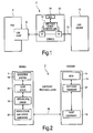
- Fig. 1 is a block schematic diagram of a bus communication system in accordance with the invention.
- the system 2 comprises a first USB Device 4 with a USB port 6, a second USB Device 8 and a dongle 10.
- the first USB Device 4 is a personal digital assistant (PDA), but it will be appreciated that the invention is applicable to any USB Device such as a mobile communications device, digital camera or a personal organizer.
- PDA personal digital assistant
- the second USB Device 8 may be any USB Device including a printer, mouse, hard disk or modem.
- the dongle 10 comprises an Embedded USB Host/Device Controller 12 with a first host port H1 and a second host port H2, and a low power Micro Controller Unit (MCU) 14.
- MCU Micro Controller Unit
- the first host port H1 of the dongle 10 may be connected, as shown in Fig. 1, to the USB port 6 of the PDA 4.
- the PDA is effectively enabled to act as a USB Host
- the second host port H2 of the dongle 10 then effectively functions as a Host port of the PDA 4.
- the PDA 4 may control communications with any USB Device connected to the second host port H2 of the dongle 10 by means of a USB bus 15.
- first host port H1 and the second host port H2 are shown here connected to the same USB Host/Device Controller 12, it would be possible for the MCU 14 to communicate with the first host port H1 and the second host port H2 through two independent USB Host/Device Controllers, the first being dedicated to communication with the PDA 4, and the second being dedicated to communication with the connected USB device, or devices, 8.
- the PDA 4 In order to allow the PDA 4 to act as a USB Host when connected to the dongle 10, the PDA 4 requires a driver update.
- the driver update is specific to the particular USB Device which is in use, and serves to add in a Virtual Hardware Abstraction Layer (VirtualHAL) software driver, which runs on top of the existing USB Device Hardware in the PDA 4.
- VirtualHAL Virtual Hardware Abstraction Layer
- Fig. 2 is a block diagram of the hardware and software in the system of Fig. 1.
- the USB Device 4 has an operating system 18, a Host Stack 20 and Device Stack and Device Hardware 22. In order to be able to act as a USB Host, the PDA 4 also runs the VirtualHAL driver software 16. When the USB Device 4 is running the VirtualHAL driver software 16, it is sometimes referred to herein as a HostOnDevice.
- the dongle 10 comprises Host Hardware 12 (that is, the USB host controller), MCU 14 and SoftHost Firmware 24.
- the SoftHost protocol layer which will be described in more detail below, controls the communications between the device 4 and the dongle 10 over the dongle connector 28.
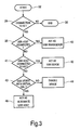
- Fig. 3 is a flow diagram illustrating the operation of the dongle 10, under the control of the MCU 14.
- the MCU polls the first host port H1 in step 34, to determine whether there is any connection thereto. If there is no connection, the process ends at step 36.
- the MCU determines in step 38 whether there is a USB Host connected to the first host port H1. If there is a USB Host connected to the first host port H1, then the process passes to step 40, in which the dongle 10 acts as a USB transceiver. That is, it passes communications directly between the first host port H1 and the second host port H2, allowing the connected USB Host to control communications with any USB device (or devices) connected to the second host port H2 in the conventional way.
- step 38 determines in step 38 that there is a USB Device, rather than a USB Host, connected to the first host port H1
- the process passes to step 41, in which it determines if there is a USB Host connected to the second host port H2. If so, then in step 42 the USB Device core within the USB Host/Device Controller 12 operates to allow conventional USB communications between the USB Device connected to the first host port H1 and the USB Host connected to the second host port H2.
- the MCU 14 enumerates the USB Device connected to the first host port H1 in step 43, and checks if it is a device running VirtualHAL. If the MCU determines in step 43 that the connected device 4 is not running VirtualHAL, it will disable the device 4 in step 44 and, for example, will trigger a flashing LED, signaling that the connected device 4 does not support VirtualHAL.
- the MCU 14 determines in step 42 that the connected device 4 is running VirtualHAL, (i.e. that it has a VirtualHAL driver 16) the MCU 14 will go into operational mode in step 46, allowing the dongle 10 (together with the device 4) to act as an alternate USB Host. In this mode, which will be described in more detail below, the dongle 10 can control communications with any USB device (or devices) connected to the second host port H2.
- a Host Stack accesses underlying USB Hardware through the HostHAL.
- a Device Stack accesses underlying USB hardware though a Device HAL.
- the SoftHost system when the Host Stack (or host station driver software) 20 needs to access the Host Hardware 12, it communicates the access operation details to the VirtualHAL Driver 16.
- the VirtualHAL Driver 16 wraps these access operation details in a pre-determined SoftHost Protocol.
- the SoftHost protocol packet is sent out through the existing USB Device Hardware 22 when the SoftHost Dongle 10 polls it for outstanding SoftHost Protocol packets.
- the VirtualHAL Driver software 16 emulates the presence of a host controller towards the host station driver software. That is, from the point of view of the Host Stack 20, communicating with the VirtualHAL Driver 16 is no different from communicating with a HostHAL in a conventional system. The Host Stack 20 will see an actual Host Hardware through the VirtualHAL Driver 16.
- the VirtualHAL Driver software 16 emulates the presence of a device controller towards the device controller (or device stack) 22.
- the VirtualHAL Driver software 16 thus translates communications between the host station driver software 20 and the device controller.
- the SoftHost Protocol provides the following access functions:
- More advanced functions could be added to improve the system performance, for example, a function that reads a register, AND/ORs it with a value and writes the amended value back into the register.
- the SoftHost Protocol defines the method by which the Host Stack 20 running on VirtualHAL may access the hardware of the Host Controller 12 using the Device Controller hardware.
- the SoftHost protocol is described in detail below.
- the term "HostDongle” is used to refer to the dongle 10
- the term “HostOnDevice” is used to refer to the device 4, namely an embedded system with USB device hardware 22, running a Host Stack 20 on VirtualHAL 16.
- the SoftHost protocol starts at the end of Fig. 3, at the point where the HostDongle 10 has enumerated the connected device 4 and the connected device 4 is confirmed to be a HostOnDevice.
- the MCU 14 sets up an interrupt pipe and polls the VirtualHAL driver 16 for data every millisecond.
- Data sent between the device 4 and dongle 10 is sent by means of the SoftHost protocol, in the form of SoftHost Packets. If the Host Stack 20 on the PDA 4 has sent a hardware access request through the VirtualHAL Driver 16, the VirtualHAL Driver 16 will send the request as a SoftHostPacket when the first host port H1 of the dongle 10 polls it through the interrupt pipe.
- the MCU 14 will retrieve this SoftHost Packet from the buffer memory of the embedded USB Host Controller 12 and execute the hardware access accordingly. If there is any data to be returned (read operations), the MCU 14 will send out the corresponding data through Host 1.
- HRU HostDongle Request Unit
- HRU_IRQ Interrupt Information
- HostOnDevice 4 would reply with NOB or CRP through this bulk-in.
- transfers start with an action by the Host.
- the SoftHost Dongle 10 is always the Host. All SoftHost transfer cycles starts with a HRU, as defined above. The current transfer cycle must be completed before the HostDongle 10 starts the next transfer cycle.
- Active bit in Header is 1 for CRP, and 0 for APR.
- CRP can be of a size of 16-64 bytes.
- the total size is made up of A number of command sets (8 bytes each) An optional data set.
- Maximum size of data set is 64-(8* number of command sets).
- the multiple command sets in a single command request packet allows a sequence of hardware accesses to be communicated in a single packet and thus reduces the latency transfer.
- Command Set is an 8-byte data structure. It contains the following information:
- the Virtual Hardware Abstraction Layer (VirtualHAL) therefore provides complete access to the target hardware on the connected dongle, using the USB Device hardware.
- the existing USB Device hardware is used as an asynchronous microprocessor interface bus to allow the USB Host Driver to access the target hardware.
- VirtualHAL provides the advantages that the hardware dongle does not need to handle USB software, which allows the dongle to be low cost, and the Host software can be handled by the embedded system on the USB Device.
- a hardware dongle that allows a USB Device to attain the capability of USB Host without changes to the existing hardware.
- the USB Device runs emulation software that can be handled by the embedded system on the USB Device. This provides the advantages that the hardware dongle does not need to handle USB software, which allows the dongle to be low cost.
- the invention has been described up to this point with reference to a system in which the VirtualHAL driver software allows the USB Device to function as a USB Host in conjunction with the dongle 10.
- similarly structured VirtualHAL driver software could be used to add in multiple interface/functions to a system with USB Device capability.
- the driver software could allows the USB Device to communicate over Bluetooth, IrDA, USB-OTG, or other communications protocols.
Claims (5)
- Station de bus (10) à utiliser dans un système de communication par bus, comprenant un premier port de communication (H2) et un second port de communication (H1), destinée à fonctionner dans un premier mode lors de la détection de la présence d'une station hôte couplée audit second port et à fonctionner dans un second mode lors de la détection de l'absence d'une station hôte couplée audit second port, caractérisée en ce que ladite station de bus (10) est destinée, dans ledit premier mode de fonctionnement, à faire passer une communication entre ladite station hôte couplée audit second port (H1) et une station de périphérique (8) couplée audit premier port (H2), et en ce que ladite station de bus (10) est en outre destinée à fonctionner comme une autre station hôte dans ledit second mode de fonctionnement, en communiquant avec ladite station de périphérique (8) couplée audit premier port (H2) suivant un protocole de communication grâce auquel ladite station de bus (10) amorce la communication.
- Station de bus suivant la revendication 1, dans laquelle ladite station de bus est destinée à fonctionner comme un émetteur- récepteur USB dans ledit premier mode de fonctionnement et à fonctionner comme un hôte USB dans ledit second mode de fonctionnement.
- Station de bus suivant la revendication 1, dans laquelle ladite station de bus comprend en outre le circuit d'émission/réception couplé audit premier port et audit second port pour faire passer les communications entre ladite station hôte couplée audit second port et à ladite station de périphérique dans ledit premier mode de fonctionnement.
- Station de bus (4) à utiliser dans un système de bus, comprenant un contrôleur de périphériques (22) couplé à un port de communication, destinée à fonctionner comme une station de périphérique, ladite station de bus étant en outre destinée à fonctionner sous le contrôle du logiciel du système, comprenant un système d'exploitation (18) et caractérisée en ce que le système comprend un logiciel pilote de station hôte (20) destiné à communiquer avec un contrôleur de hôte et à faire passer des informations vers et depuis le système d'exploitation, dans laquelle ledit logiciel de système comprend en outre un logiciel d'émulation d'hôte (16) destiné à émuler la présence d'un contrôleur d'hôte vers le logiciel de pilote de station hôte (20) et la présence de logiciel pilote de station de périphérique vers le contrôleur de périphérique (22), étant en outre destiné à transposer les communications du logiciel de pilote de station hôte (20) vers le contrôleur de périphérique (22) et vice versa.
- Système de communication par bus comprenant une première station de bus (4) comprenant un port de communication de périphérique (6) et une seconde station de bus (10), ladite seconde station de bus comprenant en outre un second port de communication (H1), ladite seconde station de bus (10) étant destinée à fonctionner dans un premier mode lors de la détection de la présence d'une station hôte couplée audit second port (H1) et à fonctionner dans un second mode lors de la détection de l'absence d'une station hôte couplée audit second port,
caractérisée en ce que la première station de bus (4) comprend un contrôleur de périphérique (22) couplé audit port de communication de périphérique et est destinée à fonctionner sous le contrôle du logiciel de système, comprenant un système d'exploitation (18) et un logiciel pilote de station hôte (20) destiné à communiquer avec un contrôleur de hôte et à faire passer des informations vers et depuis le système d'exploitation, dans laquelle ledit logiciel de système comprend en outre un logiciel d'émulation de l'hôte (16) destiné à émuler la présence d'un contrôleur de hôte vers le logiciel pilote de station de hôte (20) et la présence de logiciel pilote de station de périphérique vers le contrôleur de périphérique (22), destiné en outre à transposer les communications depuis le logiciel pilote de station hôte (20) vers le contrôleur de périphérique (22) et vice versa.
Applications Claiming Priority (3)
| Application Number | Priority Date | Filing Date | Title |
|---|---|---|---|
| WOPCT/SG02/00239 | 2002-09-24 | ||
| SG0200239 | 2002-09-24 | ||
| PCT/IB2003/002236 WO2004029817A1 (fr) | 2002-09-24 | 2003-05-22 | Systeme de connexion de bus |
Publications (2)
| Publication Number | Publication Date |
|---|---|
| EP1546897A1 EP1546897A1 (fr) | 2005-06-29 |
| EP1546897B1 true EP1546897B1 (fr) | 2006-12-20 |
Family
ID=32041145
Family Applications (1)
| Application Number | Title | Priority Date | Filing Date |
|---|---|---|---|
| EP03725545A Expired - Lifetime EP1546897B1 (fr) | 2002-09-24 | 2003-05-22 | Systeme de connexion de bus |
Country Status (9)
| Country | Link |
|---|---|
| US (1) | US7640385B2 (fr) |
| EP (1) | EP1546897B1 (fr) |
| JP (2) | JP2006500672A (fr) |
| CN (1) | CN1685326B (fr) |
| AT (1) | ATE349044T1 (fr) |
| AU (1) | AU2003228076A1 (fr) |
| DE (1) | DE60310586T2 (fr) |
| TW (1) | TWI320142B (fr) |
| WO (1) | WO2004029817A1 (fr) |
Families Citing this family (47)
| Publication number | Priority date | Publication date | Assignee | Title |
|---|---|---|---|---|
| JP3962696B2 (ja) * | 2003-02-21 | 2007-08-22 | キヤノン株式会社 | 情報処理装置とその制御方法及び制御プログラム |
| US7174405B1 (en) * | 2003-06-06 | 2007-02-06 | Cisco Technology, Inc. | Method and system for replacing a read-modify-write operation with an atomic set-bits or clear-bits operation |
| TWI241520B (en) * | 2003-07-08 | 2005-10-11 | Ours Technology Inc | Universal serial bus device for exchange data each other |
| TWI226551B (en) * | 2003-10-28 | 2005-01-11 | Prolific Technology Inc | Multi-function wireless bridge for USB and associated system |
| CN1906559B (zh) * | 2003-12-30 | 2010-10-13 | 威步系统股份公司 | 用于控制数据处理设备的方法 |
| CN100375495C (zh) * | 2004-04-26 | 2008-03-12 | 全友电脑股份有限公司 | 可独立运作的扫描仪 |
| ATE467183T1 (de) | 2004-05-28 | 2010-05-15 | Nxp Bv | Busverbindungseinrichtung |
| CN100416531C (zh) * | 2004-08-30 | 2008-09-03 | 旺玖科技股份有限公司 | 多功能通用串行总线无线桥接装置及系统装置 |
| DE102004042172A1 (de) | 2004-08-31 | 2006-03-09 | Advanced Micro Devices, Inc., Sunnyvale | Segmentierter chipinterner Speicher und Arbitrierung anfordernder Einrichtungen |
| WO2006031681A2 (fr) * | 2004-09-10 | 2006-03-23 | Logitech Europe S.A. | Communication de signaux de commande pour casques audio sans fil |
| CN100388256C (zh) * | 2004-09-17 | 2008-05-14 | 宇瞻科技股份有限公司 | Usb存取装置 |
| CN1329808C (zh) * | 2004-10-09 | 2007-08-01 | 宇瞻科技股份有限公司 | 数据编码和解码装置 |
| DE102004057756B4 (de) * | 2004-11-30 | 2009-08-06 | Advanced Micro Devices Inc., Sunnyvale | USB-Steuerungseinrichtung mit OTG-Steuerungseinheit |
| US7606951B2 (en) | 2004-11-12 | 2009-10-20 | Woodbridge Nancy G | Memory reuse for multiple endpoints in USB device |
| US20060106962A1 (en) * | 2004-11-17 | 2006-05-18 | Woodbridge Nancy G | USB On-The-Go implementation |
| DE102005009021A1 (de) | 2005-02-28 | 2006-09-07 | Advanced Micro Devices Inc., Sunnyvale | Vereinheitliche USB OTG-Steuerungseinheit |
| US20060206631A1 (en) * | 2005-03-09 | 2006-09-14 | Chin-Chen Kuo | Data duplication method and system used between USB devices |
| CN100401280C (zh) * | 2005-06-08 | 2008-07-09 | 北京飞天诚信科技有限公司 | 通用串行总线数据传输方法 |
| EP1760599B1 (fr) * | 2005-08-15 | 2008-05-14 | Research In Motion Limited | Connecteur périphérique universel |
| US8024500B2 (en) | 2005-08-15 | 2011-09-20 | Research In Motion Limited | Universal peripheral connector |
| FR2895187B1 (fr) * | 2005-12-21 | 2010-12-17 | Eastman Kodak Co | Station d'accueil d'equipements hotes mobiles et procede de partage de ressources utilisant la station |
| US8035368B2 (en) * | 2006-02-13 | 2011-10-11 | Freescale Semiconductor, Inc. | Integrated circuit, universal serial bus on-the-go power source and methods for use therewith |
| US20100225953A1 (en) * | 2006-03-20 | 2010-09-09 | Ernst Engst | Method and assembly for releasing and configuring specific system operations of a printer or photocopier |
| CN101136000B (zh) * | 2006-09-01 | 2011-01-05 | 飞思卡尔半导体公司 | 实现sd主机/从属设备的应用处理器电路和电子设备 |
| JP2008107997A (ja) * | 2006-10-24 | 2008-05-08 | Seiko Epson Corp | データ通信方法、データ通信装置及びデータ通信システム |
| US7558899B2 (en) * | 2007-04-04 | 2009-07-07 | Imation Corp. | Dongle configured to electrically couple a data storage device and a host computing device |
| US8315269B1 (en) | 2007-04-18 | 2012-11-20 | Cypress Semiconductor Corporation | Device, method, and protocol for data transfer between host device and device having storage interface |
| GB2489344B (en) * | 2007-06-15 | 2012-12-05 | Apple Inc | circuitry and method for regulating a power supply signal |
| TWI448902B (zh) | 2007-08-24 | 2014-08-11 | Cypress Semiconductor Corp | 具頁存取基礎處理器介面之橋接裝置 |
| US8090894B1 (en) * | 2007-09-21 | 2012-01-03 | Cypress Semiconductor Corporation | Architectures for supporting communication and access between multiple host devices and one or more common functions |
| US20090276549A1 (en) * | 2008-05-01 | 2009-11-05 | Nokia Corporation | Access for host stacks |
| US8170844B2 (en) * | 2008-05-02 | 2012-05-01 | Northrop Grumman Guidance And Electronics Company, Inc. | Estimation of probability of lambda failure through employment of lookup table |
| US8082381B2 (en) * | 2008-09-02 | 2011-12-20 | Nvidia Corporation | Connecting a plurality of peripherals |
| US20100115116A1 (en) * | 2008-11-03 | 2010-05-06 | Micron Technology, Inc. | System and method for switching communication protocols in electronic interface devices |
| US8103803B2 (en) * | 2008-11-21 | 2012-01-24 | Nvidia Corporation | Communication between a processor and a controller |
| US8610732B2 (en) * | 2008-12-11 | 2013-12-17 | Nvidia Corporation | System and method for video memory usage for general system application |
| US8677074B2 (en) * | 2008-12-15 | 2014-03-18 | Nvidia Corporation | Shared memory access techniques |
| US7970976B2 (en) * | 2009-03-01 | 2011-06-28 | Qualcomm Incorporated | Remote memory access using reversible host/client interface |
| TWI385533B (zh) * | 2009-05-11 | 2013-02-11 | Via Tech Inc | 電腦系統、資料交換裝置以及資料交換方法 |
| US8737064B2 (en) * | 2010-01-12 | 2014-05-27 | Microsoft Corporation | Electronic device stand |
| US8373658B2 (en) * | 2010-05-24 | 2013-02-12 | Cywee Group Limited | Motion sensing system |
| US20120259939A1 (en) * | 2011-04-05 | 2012-10-11 | Timothy James Wessman | Calculator |
| CN102820980B (zh) * | 2011-06-08 | 2018-11-06 | 南京中兴新软件有限责任公司 | 一种下发命令的设备及方法 |
| JP5907550B2 (ja) * | 2011-08-31 | 2016-04-26 | Necプラットフォームズ株式会社 | Usb機器およびusb機器の制御方法 |
| JP5734825B2 (ja) | 2011-09-09 | 2015-06-17 | 富士通コンポーネント株式会社 | 通信装置及び通信装置の制御方法 |
| CN103729324A (zh) * | 2014-01-22 | 2014-04-16 | 浪潮电子信息产业股份有限公司 | 一种基于usb3.0接口的云存储文件安全保护装置 |
| US20180113829A1 (en) * | 2015-06-01 | 2018-04-26 | Sony Corporation | Electronic apparatus and coupling method |
Family Cites Families (14)
| Publication number | Priority date | Publication date | Assignee | Title |
|---|---|---|---|---|
| US5784581A (en) * | 1996-05-03 | 1998-07-21 | Intel Corporation | Apparatus and method for operating a peripheral device as either a master device or a slave device |
| US6131125A (en) * | 1997-11-14 | 2000-10-10 | Kawasaki Lsi U.S.A., Inc. | Plug-and-play data cable with protocol translation |
| US6370603B1 (en) * | 1997-12-31 | 2002-04-09 | Kawasaki Microelectronics, Inc. | Configurable universal serial bus (USB) controller implemented on a single integrated circuit (IC) chip with media access control (MAC) |
| TW455805B (en) | 1998-02-26 | 2001-09-21 | Winbond Electronics Corp | Converter allowing data communications equipment to transmit data to data terminal equipment through universal serial bus and the control method thereof |
| JP2000196986A (ja) * | 1998-12-25 | 2000-07-14 | Olympus Optical Co Ltd | 電子的撮像装置 |
| JP2000196648A (ja) * | 1998-12-28 | 2000-07-14 | Toshiba Corp | 電子機器制御方法および電子機器制御装置 |
| JP2000209238A (ja) * | 1999-01-14 | 2000-07-28 | Toshiba Corp | 電子機器制御方法および電子機器制御装置 |
| GB2350212B (en) * | 1999-02-09 | 2003-10-08 | Adder Tech Ltd | Data routing device and system |
| JP2000316006A (ja) * | 1999-04-28 | 2000-11-14 | Nec Corp | バスマネージャ機能自動切換対応ノード、移動端末、及び、移動端末システム |
| JP2002055936A (ja) * | 2000-08-08 | 2002-02-20 | Toshiba Corp | Usbデバイス機器、usbデバイス機器間の通信システムおよび通信方法 |
| JP2002116853A (ja) * | 2000-10-05 | 2002-04-19 | Tdk Corp | Usb搭載電子機器及びそれに用いるusbケーブル |
| US7000057B1 (en) * | 2002-02-11 | 2006-02-14 | Cypress Semiconductor Corp. | Method and apparatus for adding OTG dual role device capability to a USB peripheral |
| US6732218B2 (en) * | 2002-07-26 | 2004-05-04 | Motorola, Inc. | Dual-role compatible USB hub device and method |
| US7152190B2 (en) * | 2004-02-03 | 2006-12-19 | Motorola Inc. | USB OTG intelligent hub/router for debugging USB OTG devices |
-
2003
- 2003-05-22 AU AU2003228076A patent/AU2003228076A1/en not_active Abandoned
- 2003-05-22 WO PCT/IB2003/002236 patent/WO2004029817A1/fr active IP Right Grant
- 2003-05-22 US US10/528,614 patent/US7640385B2/en not_active Expired - Fee Related
- 2003-05-22 CN CN038226685A patent/CN1685326B/zh not_active Expired - Fee Related
- 2003-05-22 JP JP2004539268A patent/JP2006500672A/ja active Pending
- 2003-05-22 AT AT03725545T patent/ATE349044T1/de not_active IP Right Cessation
- 2003-05-22 DE DE60310586T patent/DE60310586T2/de not_active Expired - Lifetime
- 2003-05-22 EP EP03725545A patent/EP1546897B1/fr not_active Expired - Lifetime
- 2003-05-28 TW TW092114417A patent/TWI320142B/zh not_active IP Right Cessation
-
2009
- 2009-10-05 JP JP2009231540A patent/JP2010061670A/ja active Pending
Also Published As
| Publication number | Publication date |
|---|---|
| US20060059289A1 (en) | 2006-03-16 |
| WO2004029817A1 (fr) | 2004-04-08 |
| AU2003228076A1 (en) | 2004-04-19 |
| EP1546897A1 (fr) | 2005-06-29 |
| TWI320142B (en) | 2010-02-01 |
| CN1685326B (zh) | 2010-05-05 |
| DE60310586D1 (de) | 2007-02-01 |
| ATE349044T1 (de) | 2007-01-15 |
| US7640385B2 (en) | 2009-12-29 |
| JP2010061670A (ja) | 2010-03-18 |
| CN1685326A (zh) | 2005-10-19 |
| TW200405172A (en) | 2004-04-01 |
| JP2006500672A (ja) | 2006-01-05 |
| DE60310586T2 (de) | 2007-10-11 |
Similar Documents
| Publication | Publication Date | Title |
|---|---|---|
| EP1546897B1 (fr) | Systeme de connexion de bus | |
| US7058748B1 (en) | ATA device control via a packet-based interface | |
| US7587528B2 (en) | Control of information units in fibre channel communications | |
| JP6266615B2 (ja) | データトンネルを用いるインタフェースを介した複数のプロトコルデータ要素の送信 | |
| KR101497001B1 (ko) | 그래픽스 멀티미디어 ic 및 그것의 동작 방법 | |
| US6115771A (en) | Method and system for converting computer peripheral equipment to SCSI-compliant devices | |
| EP2316075B1 (fr) | Procédé et appareil de connexion de dispositifs usb à un ordinateur distant | |
| US7802034B2 (en) | Method for performing full transfer automation in a USB controller | |
| US20080162741A1 (en) | Wireless usb hub | |
| US7162566B2 (en) | USB-based host-to-host networking method | |
| EP1899830B1 (fr) | Mecanisme de reessai de couche transport par un port cible dans un protocole serialise automatise | |
| WO2008011727A1 (fr) | Procédé et appareil de distribution de fonctions de concentrateurs usb dans un réseau | |
| KR20040041623A (ko) | 버스 시스템 및 버스 인터페이스 | |
| CN102843435A (zh) | 一种在集群系统中存储介质的访问、响应方法和系统 | |
| US20040103163A1 (en) | Serial bus disk extender and portable storage device | |
| WO1996029792A2 (fr) | Protocole de communication pour le transfert de donnees entre processors | |
| US20070022226A1 (en) | Direct memory access system for iSCSI | |
| EP2300925B1 (fr) | Système destiné à connecter un contrôleur de matrice scsi en série à un réseau de stockage (san) | |
| KR101005397B1 (ko) | 버스 스테이션 및 버스 통신 시스템 | |
| WO2008082530A1 (fr) | Procédé et appareil permettant d'exécuter une automatisation de transfert intégrale dans un contrôleur usb | |
| US20050273541A1 (en) | Circuit and method for adaptively recognizing a data packet in a universal serial bus network device | |
| US7532625B2 (en) | Block transfer for WLAN device control | |
| JP2003523576A (ja) | リンクブリッジ | |
| JP2003523575A (ja) | 結合システムおよび方法 |
Legal Events
| Date | Code | Title | Description |
|---|---|---|---|
| PUAI | Public reference made under article 153(3) epc to a published international application that has entered the european phase |
Free format text: ORIGINAL CODE: 0009012 |
|
| 17P | Request for examination filed |
Effective date: 20050425 |
|
| AK | Designated contracting states |
Kind code of ref document: A1 Designated state(s): AT BE BG CH CY CZ DE DK EE ES FI FR GB GR HU IE IT LI LU MC NL PT RO SE SI SK TR |
|
| AX | Request for extension of the european patent |
Extension state: AL LT LV MK |
|
| DAX | Request for extension of the european patent (deleted) | ||
| GRAP | Despatch of communication of intention to grant a patent |
Free format text: ORIGINAL CODE: EPIDOSNIGR1 |
|
| GRAS | Grant fee paid |
Free format text: ORIGINAL CODE: EPIDOSNIGR3 |
|
| GRAA | (expected) grant |
Free format text: ORIGINAL CODE: 0009210 |
|
| AK | Designated contracting states |
Kind code of ref document: B1 Designated state(s): AT BE BG CH CY CZ DE DK EE ES FI FR GB GR HU IE IT LI LU MC NL PT RO SE SI SK TR |
|
| PG25 | Lapsed in a contracting state [announced via postgrant information from national office to epo] |
Ref country code: IT Free format text: LAPSE BECAUSE OF FAILURE TO SUBMIT A TRANSLATION OF THE DESCRIPTION OR TO PAY THE FEE WITHIN THE PRESCRIBED TIME-LIMIT;WARNING: LAPSES OF ITALIAN PATENTS WITH EFFECTIVE DATE BEFORE 2007 MAY HAVE OCCURRED AT ANY TIME BEFORE 2007. THE CORRECT EFFECTIVE DATE MAY BE DIFFERENT FROM THE ONE RECORDED. Effective date: 20061220 Ref country code: RO Free format text: LAPSE BECAUSE OF FAILURE TO SUBMIT A TRANSLATION OF THE DESCRIPTION OR TO PAY THE FEE WITHIN THE PRESCRIBED TIME-LIMIT Effective date: 20061220 Ref country code: AT Free format text: LAPSE BECAUSE OF FAILURE TO SUBMIT A TRANSLATION OF THE DESCRIPTION OR TO PAY THE FEE WITHIN THE PRESCRIBED TIME-LIMIT Effective date: 20061220 Ref country code: SI Free format text: LAPSE BECAUSE OF FAILURE TO SUBMIT A TRANSLATION OF THE DESCRIPTION OR TO PAY THE FEE WITHIN THE PRESCRIBED TIME-LIMIT Effective date: 20061220 Ref country code: DK Free format text: LAPSE BECAUSE OF FAILURE TO SUBMIT A TRANSLATION OF THE DESCRIPTION OR TO PAY THE FEE WITHIN THE PRESCRIBED TIME-LIMIT Effective date: 20061220 Ref country code: CZ Free format text: LAPSE BECAUSE OF FAILURE TO SUBMIT A TRANSLATION OF THE DESCRIPTION OR TO PAY THE FEE WITHIN THE PRESCRIBED TIME-LIMIT Effective date: 20061220 Ref country code: BE Free format text: LAPSE BECAUSE OF FAILURE TO SUBMIT A TRANSLATION OF THE DESCRIPTION OR TO PAY THE FEE WITHIN THE PRESCRIBED TIME-LIMIT Effective date: 20061220 Ref country code: FI Free format text: LAPSE BECAUSE OF FAILURE TO SUBMIT A TRANSLATION OF THE DESCRIPTION OR TO PAY THE FEE WITHIN THE PRESCRIBED TIME-LIMIT Effective date: 20061220 Ref country code: SK Free format text: LAPSE BECAUSE OF FAILURE TO SUBMIT A TRANSLATION OF THE DESCRIPTION OR TO PAY THE FEE WITHIN THE PRESCRIBED TIME-LIMIT Effective date: 20061220 Ref country code: CH Free format text: LAPSE BECAUSE OF FAILURE TO SUBMIT A TRANSLATION OF THE DESCRIPTION OR TO PAY THE FEE WITHIN THE PRESCRIBED TIME-LIMIT Effective date: 20061220 Ref country code: LI Free format text: LAPSE BECAUSE OF FAILURE TO SUBMIT A TRANSLATION OF THE DESCRIPTION OR TO PAY THE FEE WITHIN THE PRESCRIBED TIME-LIMIT Effective date: 20061220 Ref country code: NL Free format text: LAPSE BECAUSE OF FAILURE TO SUBMIT A TRANSLATION OF THE DESCRIPTION OR TO PAY THE FEE WITHIN THE PRESCRIBED TIME-LIMIT Effective date: 20061220 |
|
| REG | Reference to a national code |
Ref country code: GB Ref legal event code: FG4D |
|
| REG | Reference to a national code |
Ref country code: CH Ref legal event code: EP |
|
| REF | Corresponds to: |
Ref document number: 60310586 Country of ref document: DE Date of ref document: 20070201 Kind code of ref document: P |
|
| REG | Reference to a national code |
Ref country code: IE Ref legal event code: FG4D |
|
| PG25 | Lapsed in a contracting state [announced via postgrant information from national office to epo] |
Ref country code: BG Free format text: LAPSE BECAUSE OF FAILURE TO SUBMIT A TRANSLATION OF THE DESCRIPTION OR TO PAY THE FEE WITHIN THE PRESCRIBED TIME-LIMIT Effective date: 20070320 Ref country code: SE Free format text: LAPSE BECAUSE OF FAILURE TO SUBMIT A TRANSLATION OF THE DESCRIPTION OR TO PAY THE FEE WITHIN THE PRESCRIBED TIME-LIMIT Effective date: 20070320 |
|
| PG25 | Lapsed in a contracting state [announced via postgrant information from national office to epo] |
Ref country code: ES Free format text: LAPSE BECAUSE OF FAILURE TO SUBMIT A TRANSLATION OF THE DESCRIPTION OR TO PAY THE FEE WITHIN THE PRESCRIBED TIME-LIMIT Effective date: 20070331 |
|
| PG25 | Lapsed in a contracting state [announced via postgrant information from national office to epo] |
Ref country code: PT Free format text: LAPSE BECAUSE OF FAILURE TO SUBMIT A TRANSLATION OF THE DESCRIPTION OR TO PAY THE FEE WITHIN THE PRESCRIBED TIME-LIMIT Effective date: 20070424 |
|
| NLV1 | Nl: lapsed or annulled due to failure to fulfill the requirements of art. 29p and 29m of the patents act | ||
| REG | Reference to a national code |
Ref country code: CH Ref legal event code: PL |
|
| ET | Fr: translation filed | ||
| PLBE | No opposition filed within time limit |
Free format text: ORIGINAL CODE: 0009261 |
|
| STAA | Information on the status of an ep patent application or granted ep patent |
Free format text: STATUS: NO OPPOSITION FILED WITHIN TIME LIMIT |
|
| 26N | No opposition filed |
Effective date: 20070921 |
|
| PG25 | Lapsed in a contracting state [announced via postgrant information from national office to epo] |
Ref country code: MC Free format text: LAPSE BECAUSE OF NON-PAYMENT OF DUE FEES Effective date: 20070531 |
|
| PG25 | Lapsed in a contracting state [announced via postgrant information from national office to epo] |
Ref country code: GR Free format text: LAPSE BECAUSE OF FAILURE TO SUBMIT A TRANSLATION OF THE DESCRIPTION OR TO PAY THE FEE WITHIN THE PRESCRIBED TIME-LIMIT Effective date: 20070321 |
|
| PG25 | Lapsed in a contracting state [announced via postgrant information from national office to epo] |
Ref country code: IE Free format text: LAPSE BECAUSE OF NON-PAYMENT OF DUE FEES Effective date: 20070522 |
|
| REG | Reference to a national code |
Ref country code: GB Ref legal event code: 732E |
|
| PG25 | Lapsed in a contracting state [announced via postgrant information from national office to epo] |
Ref country code: EE Free format text: LAPSE BECAUSE OF FAILURE TO SUBMIT A TRANSLATION OF THE DESCRIPTION OR TO PAY THE FEE WITHIN THE PRESCRIBED TIME-LIMIT Effective date: 20061220 |
|
| REG | Reference to a national code |
Ref country code: FR Ref legal event code: TP |
|
| PG25 | Lapsed in a contracting state [announced via postgrant information from national office to epo] |
Ref country code: LU Free format text: LAPSE BECAUSE OF NON-PAYMENT OF DUE FEES Effective date: 20070522 Ref country code: CY Free format text: LAPSE BECAUSE OF FAILURE TO SUBMIT A TRANSLATION OF THE DESCRIPTION OR TO PAY THE FEE WITHIN THE PRESCRIBED TIME-LIMIT Effective date: 20061220 |
|
| PG25 | Lapsed in a contracting state [announced via postgrant information from national office to epo] |
Ref country code: HU Free format text: LAPSE BECAUSE OF FAILURE TO SUBMIT A TRANSLATION OF THE DESCRIPTION OR TO PAY THE FEE WITHIN THE PRESCRIBED TIME-LIMIT Effective date: 20070621 Ref country code: TR Free format text: LAPSE BECAUSE OF FAILURE TO SUBMIT A TRANSLATION OF THE DESCRIPTION OR TO PAY THE FEE WITHIN THE PRESCRIBED TIME-LIMIT Effective date: 20061220 |
|
| REG | Reference to a national code |
Ref country code: FR Ref legal event code: PLFP Year of fee payment: 13 |
|
| REG | Reference to a national code |
Ref country code: FR Ref legal event code: PLFP Year of fee payment: 14 |
|
| REG | Reference to a national code |
Ref country code: DE Ref legal event code: R082 Ref document number: 60310586 Country of ref document: DE Representative=s name: GRUENECKER PATENT- UND RECHTSANWAELTE PARTG MB, DE Ref country code: DE Ref legal event code: R081 Ref document number: 60310586 Country of ref document: DE Owner name: OCT CIRCUIT TECHNOLOGIES INTERNATIONAL LTD., IE Free format text: FORMER OWNER: NXP B.V., EINDHOVEN, NL |
|
| REG | Reference to a national code |
Ref country code: FR Ref legal event code: PLFP Year of fee payment: 15 |
|
| PGFP | Annual fee paid to national office [announced via postgrant information from national office to epo] |
Ref country code: DE Payment date: 20170420 Year of fee payment: 15 Ref country code: FR Payment date: 20170421 Year of fee payment: 15 Ref country code: GB Payment date: 20170426 Year of fee payment: 15 |
|
| REG | Reference to a national code |
Ref country code: DE Ref legal event code: R119 Ref document number: 60310586 Country of ref document: DE |
|
| GBPC | Gb: european patent ceased through non-payment of renewal fee |
Effective date: 20180522 |
|
| PG25 | Lapsed in a contracting state [announced via postgrant information from national office to epo] |
Ref country code: FR Free format text: LAPSE BECAUSE OF NON-PAYMENT OF DUE FEES Effective date: 20180531 Ref country code: DE Free format text: LAPSE BECAUSE OF NON-PAYMENT OF DUE FEES Effective date: 20181201 Ref country code: GB Free format text: LAPSE BECAUSE OF NON-PAYMENT OF DUE FEES Effective date: 20180522 |